DOI:
10.1039/D1RA00803J
(Review Article)
RSC Adv., 2021,
11, 12288-12305
Yolk–shell nanostructures: synthesis, photocatalysis and interfacial charge dynamics
Received
30th January 2021
, Accepted 16th March 2021
First published on 29th March 2021
Abstract
Solar energy has long been regarded as a promising alternative and sustainable energy source. In this regard, photocatalysts emerge as a versatile paradigm that can practically transform solar energy into chemical energy. At present, unsatisfactory conversion efficiency is a major obstacle to the widespread deployment of photocatalysis technology. Many structural engineering strategies have been proposed to address the issue of insufficient activity for semiconductor photocatalysts. Among them, creation of yolk–shell nanostructures which possess many beneficial features, such as large surface area, efficient light harvesting, homogeneous catalytic environment and enhanced molecular diffusion kinetics, has attracted particular attention. This review summarizes the developments that have been made for the preparation and photocatalytic applications of yolk–shell nanostructures. Additional focus is placed on the realization of interfacial charge dynamics and the possibility of achieving spatial separation of charge carriers for this unique nanoarchitecture as charge transfer is the most critical factor determining the overall photocatalytic efficiency. A future perspective that can facilitate the advancement of using yolk–shell nanostructures in sophisticated photocatalytic systems is also presented.
 Yi-An Chen | Yi-An Chen received her bachelor's degree from the Department of Materials Science and Engineering at National Chiao Tung University in Taiwan in 2019. Currently, she is pursuing her PhD degree under the supervision of Prof. Yung-Jung Hsu in the Department of Materials Science and Engineering at National Chiao Tung University. She specializes in the synthesis and characterizations of hollow nanostructures comprising metals and semiconductors as well as applications in the fields of photoconversion and electrochemistry. |
 Yu-Ting Wang | Yu-Ting Wang received her bachelor's degree in Materials Science and Engineering from National Chiao Tung University, Taiwan, in 2019. She is presently a PhD student in the Department of Materials Science and Engineering at National Chiao Tung University under the supervision of Prof. Yung-Jung Hsu. She is currently working on the research topic of TiO2-based nanocomposites and their applications in photocatalysis. |
 Hyun Sik Moon | Hyun Sik Moon received his BSc in Nanotechnology Engineering from the University of Waterloo, Canada. He has been a PhD candidate in the Department of Chemical Engineering at Pohang University of Science and Technology, South Korea, under the supervision of Prof. Kijung Yong since 2018. His current research focuses on the synthesis of photocatalytic nanomaterials and their application to solar-fuel production. |
 Kijung Yong | Kijung Yong received his BS and MS in Chemical Engineering from Yonsei University, Korea; his PhD in Chemical Engineering from Carnegie Mellon University. After his postdoctoral fellow at University of Texas at Austin, he is currently a professor in the Department of Chemical Engineering, Pohang University of Science and Technology, South Korea, and an Editor of Applied Surface Science (Elsevier). His research expertise is in surface chemistry, wettability control and design of inorganic materials for solar energy conversion. |
 Yung-Jung Hsu | Yung-Jung Hsu is a Professor at the Department of Materials Science and Engineering, National Chiao Tung University, Taiwan. He received his bachelor's degree and PhD degree in Chemical Engineering from National Tsing Hua University in Taiwan. After working as a postdoctoral fellow at National Tsing Hua University, he joined National Chiao Tung University and started an independent research career in 2007. His research interests include design of advanced nanostructures, investigation of interfacial charge carrier dynamics and development of renewable energy technology. |
1. Introduction
The past decade has witnessed an urgent demand for alternative energy, which has prompted academia and industry to devote effort to green energy technology. The sun is one of the essential elements for human life, and it can be regarded as an almost inexhaustible clean, renewable energy source. The difficulty is how to utilize this natural source efficiently. Photocatalysts are media which can convert solar energy into chemical energy. This feature makes photocatalysis competitive among different energy conversion technologies. H2, O2 and hydrocarbons, which can be obtained by photocatalytic water splitting1,2 and CO2 reduction,3,4 respectively, are considered as potential alternative fuels to replace fossil fuels. No matter how these alternative fuels are consumed, the products after usage are clean and eco-friendly, complying with the core concept of sustainable development. In addition to producing green fuels, photocatalysis can also be operated to conduct wastewater treatment5,6 and environmental remediation.7,8 Using photocatalysts to decompose organic substances (e.g. antibiotics, dyes, bacteria) and inorganic toxicants (e.g. heavy metal ions, salt anions) is particularly attractive as it provides a feasible solution to the headache of the ever-rising universal environmental change. Moreover, photocatalysis can mediate the high costs and complicated processing in the manufacture of value-added chemicals.9,10 Continuous effort has been devoted to the production of high value-added organic compounds by photocatalytic reactions.
The mechanism of photocatalysis can be divided into three primary steps. The first is to apply light irradiation with sufficient energy to semiconductor photocatalysts; the second is the generation of electron–hole pairs and the subsequent charge carrier transfer; the third comprises the occurrence of surface redox reactions mediated by photoexcited electrons and holes. From a thermodynamics point of view, the photoexcited electrons must have a sufficiently high reducing power in order to manage the desired reduction reactions. In other words, the conduction band (CB) level of the selected photocatalyst must be located at a potential more cathodic than the potential required for the reduction reactions. Similarly, the valence band (VB) level of semiconductor should lie in an adequately anodic potential to endow photoexcited holes with enough oxidizing power capable of conducting oxidation reactions. During the photocatalytic process, there however exist many handicaps that can result in low photocatalytic activity. These disservices include poor light absorption, rapid electron–hole recombination, and sluggish charge transfer kinetics. As dragged by such feet of clay, only a limited amount of charge carriers can actually participate in surface redox reactions. This dilemma could be ameliorated by designing composite photocatalysts with well-defined structural and compositional heterogeneity, in which the attributes of individual components can be combined. Much significantly, integrating multiple components to create heterojunction can modify electronic band structure, rectifying charge transfer behavior to increase carrier utilization efficiency. Till now, various composite nanostructures have been proposed as the photocatalyst paradigm to construct superior photocatalytic systems. Representative examples are doped/alloyed nanocrystals,11–16 particle-decorated nanostructures,17–40 heterodimers,41 core–shell nanocrystals,42–47 and yolk–shell nanostructures.48,49 Here, yolk–shell nanostructures stand for a newly emerging photocatalyst platform, which are composed of a movable core surrounded by a permeable shell with void space. Such a peculiar architecture possesses several noteworthy advantages, including confined space which can facilitate the diffusion of reacting species, and large surface area which can provide abundant active sites. Besides, the incident light may undergo multiple reflections inside the void space and thus conduce to photon harvesting. Most importantly, the electronic band alignment between yolk and shell components can induce effective separation of photoexcited electrons and holes, which is an indispensable feature for superior photocatalytic efficiency.
Considerable effort in recent years has been made to devise feasible synthetic approaches to yolk–shell nanostructures and demonstrate their practice in photocatalytic applications. As illustrated in Scheme 1, this review gives a comprehensive retrospection on the preparation and photocatalytic applications of yolk–shell nanostructures. Additional focus is placed on the realization of interfacial charge dynamics and the possibility of achieving spatial separation of charge carriers for this unique nanoarchitecture as charge transfer is the most critical factor determining the overall photocatalytic efficiency. The review ends with a summary and future perspective that can facilitate the advancement of using yolk–shell nanostructures in sophisticated photocatalytic systems. For readers who are interested in acquiring the development of photocatalysts technology based on other types of composite nanostructures, we recommend some recent review articles.50–58
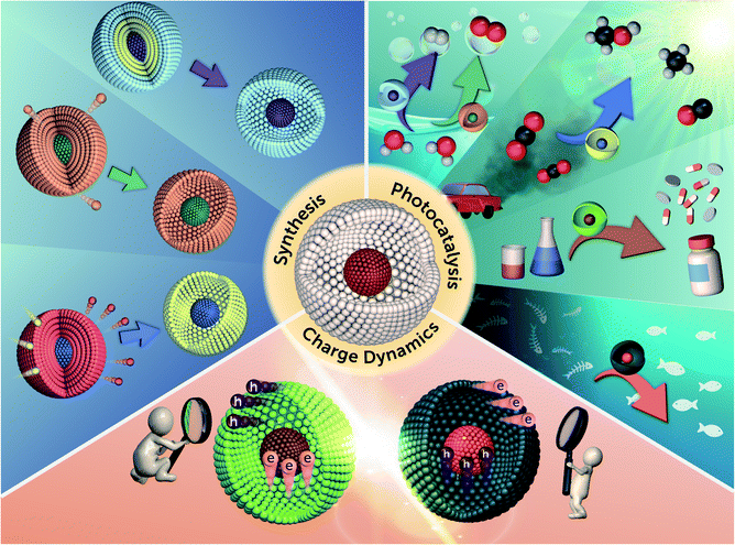 |
| | Scheme 1 Schematic illustration for the synthesis, photocatalysis and charge dynamics of yolk–shell nanostructures. | |
2. Synthetic approach
Base on the mechanism of void space formation, the synthetic approach to yolk–shell nanostructures can be divided into five categories. Kirkendall effect and galvanic replacement are both relevant to ion exchange, but the former is derived from different solubility products and the latter is caused by distinct redox potentials. Ostwald ripening is a crystal growth process involving the dissolution of particles with smaller size for deposition on larger particles. This process can be exploited to produce void space as the dissolved particles contract. Chemical etching creates void space at the expense of sacrificial templates by selective etching. Hollow structure can also be generated through physical volatilization or oxidative decomposition by means of thermal treatment. The following section further describes the details of these synthetic systems.
2.1 Kirkendall effect
Diffusion couple has been widely exploited to synthesize hollow structure. On account of the different diffusion rates, voids can be generated as two ions encounter, which is known as Kirkendall effect. At present, plenty of works have adopted this principle to prepare for yolk–shell nanostructures with various compositions, e.g. Se–SnO2,59 Sn/Sn2Co3–CoSnO3/Co3O4,60 Pt–CoO,61 Au–Fe3O4![[thin space (1/6-em)]](https://www.rsc.org/images/entities/char_2009.gif) 62 and Au–CdS.63 Chiu et al. successfully demonstrated the growth of Au–CdS yolk–shell nanostructures by Kirkendall effect.63 The experimental procedure is shown in Fig. 1A. The citrate-protected Au nanoparticles (NPs) were first subjected to coordination of Cu2+ ions via the surface carboxyl groups. A uniform layer of Cu2O can then be coated on each of the Au NPs to produce Au–Cu2O core–shell NP template. Next, Na2S was added to the Au–Cu2O suspension, transforming Cu2O shell into Cu7S4 as a result of the lower solubility product of Cu7S4 than Cu2O. In addition to the compositional change, Kirkendall voids were also generated at the shell layer by virtue of the faster outward diffusion of Cu2+ relative to the inward diffusion of S2−. Lastly, cation exchange was performed to convert Cu7S4 to CdS, producing Au–CdS yolk–shell nanostructures. Notably, changing the Au NP/Cu2+ ratio during the synthesis of Au–Cu2O template can produce Au–CdS with controllable void size. Fig. 1B–E shows the TEM images of Au–CdS with increasing void sizes from 40.2 ± 3.3 nm to 64.0 ± 6.3 nm. These yolk–shell nanostructures all possessed a constant shell thickness of around 11.5 ± 0.4 nm. Overall, Kirkendall effect represents a potentially universal strategy for the synthesis of yolk–shell nanostructures. As long as the difference in solubility product is deliberately considered, yolk–shell nanostructures with desired compositions can be obtained.
62 and Au–CdS.63 Chiu et al. successfully demonstrated the growth of Au–CdS yolk–shell nanostructures by Kirkendall effect.63 The experimental procedure is shown in Fig. 1A. The citrate-protected Au nanoparticles (NPs) were first subjected to coordination of Cu2+ ions via the surface carboxyl groups. A uniform layer of Cu2O can then be coated on each of the Au NPs to produce Au–Cu2O core–shell NP template. Next, Na2S was added to the Au–Cu2O suspension, transforming Cu2O shell into Cu7S4 as a result of the lower solubility product of Cu7S4 than Cu2O. In addition to the compositional change, Kirkendall voids were also generated at the shell layer by virtue of the faster outward diffusion of Cu2+ relative to the inward diffusion of S2−. Lastly, cation exchange was performed to convert Cu7S4 to CdS, producing Au–CdS yolk–shell nanostructures. Notably, changing the Au NP/Cu2+ ratio during the synthesis of Au–Cu2O template can produce Au–CdS with controllable void size. Fig. 1B–E shows the TEM images of Au–CdS with increasing void sizes from 40.2 ± 3.3 nm to 64.0 ± 6.3 nm. These yolk–shell nanostructures all possessed a constant shell thickness of around 11.5 ± 0.4 nm. Overall, Kirkendall effect represents a potentially universal strategy for the synthesis of yolk–shell nanostructures. As long as the difference in solubility product is deliberately considered, yolk–shell nanostructures with desired compositions can be obtained.
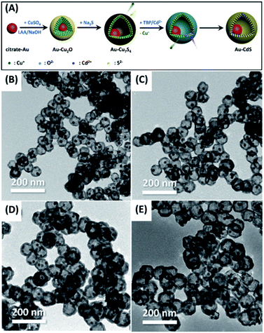 |
| | Fig. 1 (A) Synthetic approach to Au–CdS yolk–shell nanostructures by Kirkendall effect. (B–E) TEM images of Au–CdS with increasing void sizes. Reproduced with permission from ref. 63. Copyright 2019, Elsevier. | |
2.2 Galvanic replacement
By choosing two elements with suitable oxidation and reduction potentials, the replacement reaction can occur spontaneously. This principle is generally used to fabricate yolk–shell nanostructures with a wide range of compositions, including Ni–SnO2/Ni3Sn2,64 Co–Au,65 Au–AgPd,66 Sb–C67 and Pd–MxCu1−x (M = Au, Pd, and Pt).68 Liu et al. ingeniously designed hollow Sb–C yolk–shell spheres from Sn–C yolk–shell structures via galvanic replacement.67 Fig. 2A displays the synthetic process. Hollow SnO2 nanospheres were first obtained in the hydrothermal reaction, followed by the uniform coating of a carbon shell. Further annealing under H2 can convert hollow SnO2 to solid Sn particles with empty space left between carbon shell and Sn core. Because Sb has a larger reducing potential than Sn (ESb3+/Sb = 0.241 V vs. SHE; ESn4+/Sn = 0.0129 V vs. SHE), adding Sb3+ can further transform Sn–C to Sb–C. In this galvanic replacement process, Sn was oxidized to Sn4+, while Sb3+ was reduced to Sb; meanwhile, structural transformation from solid Sn to hollow Sb occurred owing to the non-equilibrium of ion diffusion between outward Sn4+ (faster) and inward Sb3+ (slower). The microstructure of Sn–C and Sb–C was explored with scanning electron microscopy (SEM) and transmission electron microscopy (TEM). As Fig. 2B–E show, Sb–C inherited the size and morphology from the parent Sn–C. The solid Sn core in Sn–C and hollow Sb yolk in Sb–C can also be clearly identified. Analogous to Kirkendall effect, galvanic replacement is a general approach to the synthesis of yolk–shell nanostructures. By pairing up suitable redox potentials, yolk–shell nanostructures with a wide range of materials combination can be readily obtained.
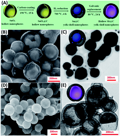 |
| | Fig. 2 (A) Synthetic approach to Sb–C yolk–shell nanospheres by galvanic replacement. (B and C) SEM and TEM images for Sn–C. (D and E) SEM and TEM images for Sb–C. Reproduced with permission from ref. 67. Copyright 2017, American Chemical Society. | |
2.3 Ostwald ripening
Ostwald ripening can account for the growth of yolk–shell nanostructures possessing single composition (homogeneous) or multiple compositions (heterogeneous). The formation of homogeneous yolk–shell structures involves the dissolution of a core particle and re-deposition of a shell layer on the gradually dissolved core. Heterogeneous yolk–shell structures on the other hand grow when core particle or shell layer itself dissolves and re-crystalizes. Because of the fascinating, synergistic properties, more attention has been paid to the synthesis of heterogeneous yolk–shell nanostructures, for instance, ZnO–C,69 Au–TiO2,70 Fe3O4–Co3O4![[thin space (1/6-em)]](https://www.rsc.org/images/entities/char_2009.gif) 71 and N-doped TiO2–C.72 Zhang et al. proposed an Ostwald ripening-based solvothermal system to prepare for N-doped TiO2–C yolk–shell spheres.72 The formation mechanism is depicted in Fig. 3A. TiO2 spheres were first grown from the aggregation and self-assembly of small TiO2 nuclei, which were simultaneously doped by N, wrapped by C and dissolved in a ripening process. Here, the addition of diethylenetriamine (DETA) as the coordinating reagent was crucial for inducing Ostwald ripening. If DETA was not added in the solvothermal reaction, solid spheres of TiO2 were otherwise obtained. Fig. 3B and C and D and E respectively show the SEM and TEM images for solid TiO2 and N-doped TiO2–C yolk–shell spheres. Solid TiO2 spheres had a size ranging from 1.0 to 1.5 μm, while N-doped TiO2–C had a mean diameter of 600–700 nm. It is generally believed that minimization of surface energy is the main cause for driving Ostwald ripening. However, the exact systematic factors of inducing ripening process remain uncontrollable.
71 and N-doped TiO2–C.72 Zhang et al. proposed an Ostwald ripening-based solvothermal system to prepare for N-doped TiO2–C yolk–shell spheres.72 The formation mechanism is depicted in Fig. 3A. TiO2 spheres were first grown from the aggregation and self-assembly of small TiO2 nuclei, which were simultaneously doped by N, wrapped by C and dissolved in a ripening process. Here, the addition of diethylenetriamine (DETA) as the coordinating reagent was crucial for inducing Ostwald ripening. If DETA was not added in the solvothermal reaction, solid spheres of TiO2 were otherwise obtained. Fig. 3B and C and D and E respectively show the SEM and TEM images for solid TiO2 and N-doped TiO2–C yolk–shell spheres. Solid TiO2 spheres had a size ranging from 1.0 to 1.5 μm, while N-doped TiO2–C had a mean diameter of 600–700 nm. It is generally believed that minimization of surface energy is the main cause for driving Ostwald ripening. However, the exact systematic factors of inducing ripening process remain uncontrollable.
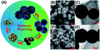 |
| | Fig. 3 (A) Synthetic approach to N-doped TiO2–C yolk–shell spheres by Ostwald ripening. (B and C) SEM and TEM images for solid TiO2. (D and E) SEM and TEM images for N-doped TiO2–C. Reproduced with permission from ref. 72. Copyright 2016, Wiley. | |
2.4 Chemical etching
Among different ways to fabricate yolk–shell nanostructures, template-assisted method represents the most straightforward approach. As long as an extra layer of etchable materials (mostly SiO2) is coated between the core and shell components, followed by selective etching to remove this layer, an empty space can be generated between the core and shell. This chemical etching concept can be adopted to prepare for a variety of yolk–shell nanostructures, such as Au–RGO/TiO2,73 Ag/TiO2–SiO2,74 Au–TiO2,75 Bi–SnO2![[thin space (1/6-em)]](https://www.rsc.org/images/entities/char_2009.gif) 76 and multi-shell TiO2.77 Hwang et al. synthesized multi-shell TiO2 hollow NPs by using the chemical etching method.77 Fig. 4A presents a scheme of the synthetic approach. First, SiO2 NPs were obtained with the typical Stöber approach, which served as core for TiO2 deposition resulting in the growth of SiO2–TiO2 core–shell (ST CS) NPs. After modified by polyvinylpyrrolidone (PVP), additional SiO2 layer can be coated on the TiO2 surface of ST CS NPs in a sol–gel reaction. Further TiO2 deposition can be achieved, leading to the formation of SiO2–TiO2–SiO2–TiO2 (STST) CS NPs. Repeated procedures can be employed to produce STSTST CS NPs, which were then calcinated and etched with NaOH to create multi-shell TiO2 hollow NPs. Fig. 4B–D show TEM images of the single-shell, double-shell, and multi-shell TiO2 hollow NPs. These NPs all possessed an overall size of around 160 nm and a shell thickness of 15 nm. Additional structural feature worth noting was that the inner shell did not constantly lie at the middle of outer shell. This observation implied that the inner shell can freely move within the outer shell, a conspicuous feature for yolk–shell nanostructures. As a template-assisted approach, chemical etching can serve as a versatile platform for the synthesis of yolk–shell nanostructures. The remaining issue is the durability of the components during the template removal process because strong acids/bases are usually used.
76 and multi-shell TiO2.77 Hwang et al. synthesized multi-shell TiO2 hollow NPs by using the chemical etching method.77 Fig. 4A presents a scheme of the synthetic approach. First, SiO2 NPs were obtained with the typical Stöber approach, which served as core for TiO2 deposition resulting in the growth of SiO2–TiO2 core–shell (ST CS) NPs. After modified by polyvinylpyrrolidone (PVP), additional SiO2 layer can be coated on the TiO2 surface of ST CS NPs in a sol–gel reaction. Further TiO2 deposition can be achieved, leading to the formation of SiO2–TiO2–SiO2–TiO2 (STST) CS NPs. Repeated procedures can be employed to produce STSTST CS NPs, which were then calcinated and etched with NaOH to create multi-shell TiO2 hollow NPs. Fig. 4B–D show TEM images of the single-shell, double-shell, and multi-shell TiO2 hollow NPs. These NPs all possessed an overall size of around 160 nm and a shell thickness of 15 nm. Additional structural feature worth noting was that the inner shell did not constantly lie at the middle of outer shell. This observation implied that the inner shell can freely move within the outer shell, a conspicuous feature for yolk–shell nanostructures. As a template-assisted approach, chemical etching can serve as a versatile platform for the synthesis of yolk–shell nanostructures. The remaining issue is the durability of the components during the template removal process because strong acids/bases are usually used.
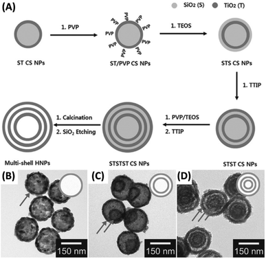 |
| | Fig. 4 (A) Synthetic approach to multi-shell TiO2 hollow NPs by chemical etching. (B–D) TEM images for (B) single-shell, (C) double-shell and (D) multi-shell TiO2. Reproduced with permission from ref. 77. Copyright 2014, Wiley. | |
2.5 Thermal treatment
Another versatile manner to manufacture yolk–shell nanostructures is to decompose and remove the volatile components under high temperature. Yolk–shell nanostructures with a variety of compositions can be created by using such a thermal treatment method. The examples include MnFe2O4–SnO2,78 C–N-doped ZnFe2O4,79 Fe–FeNx,80 C–TiO2![[thin space (1/6-em)]](https://www.rsc.org/images/entities/char_2009.gif) 81 and Fe2O3.82 Son et al. successfully synthesize Fe2O3 yolk–shell particles through multiple-step spray pyrolysis.82 Fig. 5A illustrates the one-pot synthetic process for the products. The sucrose-containing droplets of Fe nitrate were first generated by ultrasonic nebulization. Upon air-drying, decomposition, polymerization and carbonization, C–Fe2O3 composite particles were obtained. Further combustion and contraction in thermal treatment gave rise to Fe2O3 yolk–shell particles. Interestingly, the shell number of the resultant yolk–shell particles can be adjusted by tuning combustion rate and temperature. Slow combustion at low temperature (600 °C) produced Fe2O3 with four shells, while fast combustion at high temperature (800 °C or 1000 °C) generated Fe2O3 with three or two shells. Fig. 5B–G show the corresponding TEM images for the three samples, which all had a similar outer diameter. The thermal treatment approach is especially suited for the synthesis of metal oxides-based yolk–shell nanostructures since high-temperature operation is needed. Similar to the concern for chemical etching approach, particular attention should be taken on the possible deterioration of materials properties under the harsh high-temperature conditions.
81 and Fe2O3.82 Son et al. successfully synthesize Fe2O3 yolk–shell particles through multiple-step spray pyrolysis.82 Fig. 5A illustrates the one-pot synthetic process for the products. The sucrose-containing droplets of Fe nitrate were first generated by ultrasonic nebulization. Upon air-drying, decomposition, polymerization and carbonization, C–Fe2O3 composite particles were obtained. Further combustion and contraction in thermal treatment gave rise to Fe2O3 yolk–shell particles. Interestingly, the shell number of the resultant yolk–shell particles can be adjusted by tuning combustion rate and temperature. Slow combustion at low temperature (600 °C) produced Fe2O3 with four shells, while fast combustion at high temperature (800 °C or 1000 °C) generated Fe2O3 with three or two shells. Fig. 5B–G show the corresponding TEM images for the three samples, which all had a similar outer diameter. The thermal treatment approach is especially suited for the synthesis of metal oxides-based yolk–shell nanostructures since high-temperature operation is needed. Similar to the concern for chemical etching approach, particular attention should be taken on the possible deterioration of materials properties under the harsh high-temperature conditions.
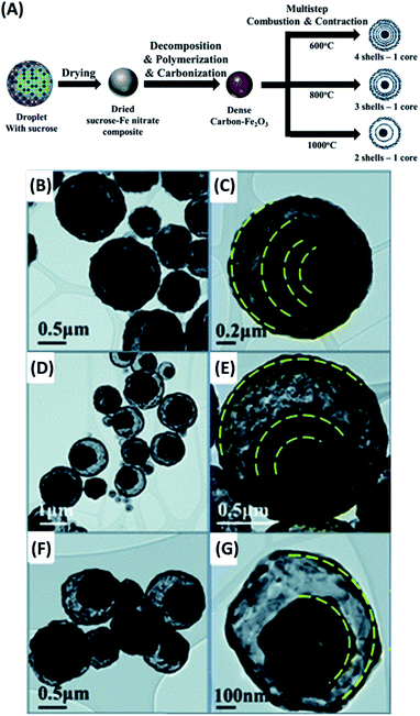 |
| | Fig. 5 (A) Synthetic approach to Fe2O3 yolk–shell particles by thermal treatment. (B–G) TEM images for Fe2O3 yolk–shell particles with (B and C) four, (D and E) three, and (F and G) two shells. Reproduced with permission from ref. 82. Copyright 2013, Royal Society of Chemistry. | |
3. Photocatalytic applications
3.1 Dye degradation
Photocatalysis has received much attention in remedying environmental problems in the past two decades. Such a pollution abatement method is especially effective for treating dyeing wastewater. The working mechanism relies on the strong oxidizing power of charge carriers produced by photocatalysts, which can completely oxidize and decompose dye molecules. Heretofore, a multitude of works have demonstrated the use of yolk–shell nanostructures for dye degradation with the aim to treat dyeing wastewater. The reported photocatalysts include Ag/TiO2–SiO2,83 Si/SiC–C/TiO2,84 Au–CeO2,85 and Ag/TiO2.86
Zhao et al. demonstrated the preparation of Ag/TiO2–SiO2 yolk–shell nanostructures with tunable void size by using chemical etching and thermal treatment approach.83 This work demonstrated the practical use of Ag/TiO2–SiO2 as photocatalysts for methylene blue (MB) degradation. As illustrated in Fig. 6A, there were several advantages of using Ag/TiO2–SiO2: (1) Ag/TiO2 yolk can function as visible photocatalyst due to the plasmonic effect of Ag; (2) tunable void size offered feasibility of optimizing photocatalytic activity; (3) porous SiO2 shell enabled light penetration and diffusion of reactive species; (4) protective function of euphotic SiO2 made possible the preservation of polymer supports (e.g. textile and cloth) for better versatility. Fig. 6B and C display SEM and TEM images for Ag/TiO2–SiO2, showing a mean overall size of 190–220 nm and recognizable porosity at SiO2 shell. Fig. 6D illustrates the optimization of photocatalytic performance of Ag/TiO2–SiO2 by controlling the void size. Here, the control over void size was realized by tuning the thickness of the sacrificial polyporrole (PPy) layer. The samples prepared with the removal of one and three PPy layers had limited void space for efficient MB degradation, whereas the sample obtained by removing seven PPY layers had opening voids that can break the structural integrity. As a result, Ag/TiO2–SiO2 prepared with the removal of five PPy layers displayed the best performance toward MB degradation. Fig. 6E further compares the photocatalytic performance of Ag/TiO2–SiO2 with pure TiO2 and pristine Ag/TiO2. A superior MB degradation efficiency was observed for Ag/TiO2–SiO2 in terms of better adsorption capacity and higher photocatalytic activity, which can be attributed to the synergistic effect illustrated in Fig. 6A. The as-synthesized Ag/TiO2–SiO2 was further loaded on cotton textiles to demonstrate the scenario of practice use. Comparative results showed that after two days of irradiation pristine Ag/TiO2-loaded textiles were inclined to structural collapse, while Ag/TiO2–SiO2-loaded textiles were structurally unscathed. This work offered an effective approach to the development of textile-supported photocatalysts with easy disposal and favorable recovery. The superior photocatalytic efficiency of yolk–shell nanostructures toward dye degradation can be recognized from the comparison of apparent rate constant of dye degradation. In a typical example,87 yolk–shell spheres of TiO2 were prepared and utilized for photodegradation of rhodamine B. The achieved pseudo-first-order rate constant of yolk–shell TiO2 spheres was 0.0057 min−1, almost four times the value of commercial TiO2 powders (P25) (0.0015 min−1).
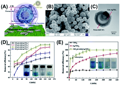 |
| | Fig. 6 (A) Plausible charge transfer mechanism for superior photocatalytic efficiency of Ag/TiO2–SiO2 toward MB degradation, (B and C) SEM and TEM images of Ag/TiO2–SiO2, (D) photocatalytic performance of Ag/TiO2–SiO2 prepared with the removal of different Ppy layers, (E) comparative results of MB degradation under visible light illumination. Reproduced with permission from ref. 83. Copyright 2019, Elsevier. | |
3.2 Toxics decomposition
As the modern chemical industries prosperously develop, toxic organic compounds, such as chlorinated and polycyclic aromatic hydrocarbons, have become global environmental pollution. Among various organic toxics, 2,4-dichlorophenol (2,4-DCP) is considered as a particularly dangerous pollutant worldwide because of its wide use as sanitizer and yet the potential lethality.88 Therefore, developing effective means to decomposing 2,4-DCP are highly required. Photocatalysis using semiconductor nanostructures is regarded as a reliable and green technique to achieve decomposition of toxic organic compounds.89,90 Previous studies have demonstrated many efficient photocatalytic systems capable of decomposing toxic substances based on the use of yolk–shell nanostructures like LaFeO3,91 Mn2O3–Mn5O8,92 and NiFe2O4–C.93
In a study led by Khan et al.,91 a delicate thermal treatment-based method was developed to prepare for yolk–shell LaFeO3 (YS-LFO) microspheres by using carbon microspheres as template. To further enhance the photocatalytic activity, YS-LFO was coupled with SnO2 particles to enhance charge separation. As displayed in Fig. 7A, SnO2 can function as photoelectron modulator to receive high-level photoexcited electrons from LFO, prohibiting their relaxation to the bottom of CB. This would largely reduce charge recombination to allow the localized holes for conducting decomposition of 2,4-DCP. Fig. 7B–D clearly show the ball-in-sphere, yolk–shell structure for YS-LFO and its successful coupling with SnO2. For YS-LFO, the solid yolk had a diameter of 200–300 nm, and the whole sphere had an outer diameter of around 1 μm. The coupled SnO2 particles had a diameter of 20 nm and were evenly distributed at the surface of YS-LFO. Fig. 7E and F compare the photocatalytic performance of 2,4-DCP decomposition among different samples. Compared to pure LFO solid particles, YS-LFO exhibited better photocatalytic efficiency. This could be attributable to the increase of surface area and the improvement in photon harvesting endowed by the yolk–shell architecture. Significantly, after coupling with 10 wt% of SnO2 (10SO/YS-LFO), the photocatalytic efficiency of YS-LFO can increase by 1.6 times, highlighting the beneficial function of SnO2. The apparent rate constant can also serve as a direct index of evaluating photocatalytic activity of toxics decomposition for yolk–shell nanostructures. For example, Bi–SnO2 yolk–shell photocatalysts showed a remarkable rate constant of tetracycline degradation (0.014 min−1) relative to pure solid Bi (0.00072 min−1).76
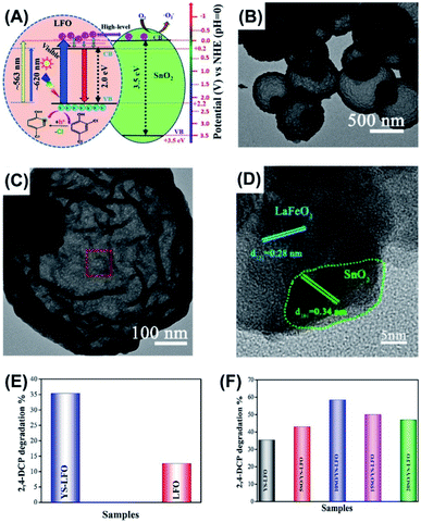 |
| | Fig. 7 (A) Plausible charge transfer mechanism for YS-LFO coupled with SnO2, (B) TEM image of YS-LFO, (C and D) TEM images of SnO2-coupled YS-LFO, (E and F) comparative results of 2,4-DCP decomposition under visible light illumination. Reproduced with permission from ref. 91. Copyright 2020, Elsevier. | |
3.3 CO2 reduction
The concentration of CO2 in atmosphere has been increasing year by year due to the prosperous development of human society. This would cause greenhouse effect and global warming, which arouses general agreement for reducing CO2 emission as well as consuming CO2 on demand. Photocatalysis on semiconductor nanostructures is a potential manner of converting CO2 into other high value-added hydrocarbon fuels, such as CH4, C2H6 and CH3OH. The goal of CO2 reduction is imitating natural photosynthesis in order to balance the global CO2 footprint. Many yolk–shell nanostructures have demonstrated remarkable photocatalytic activity toward CO2 reduction, including Au–TiO2,94 Au-g-C3N4/SnS,95 Ni–SiO2,96 TiO2,97 and TiO2−x.98
Ziarati et al. obtained a yolk–shell nanostructure of TiO2 (Y@S–TiO2) based on the Ostwald ripening approach in a solvothermal reaction.98 After hydrogenation treatment, the TiO2−x yolk–shell nanostructures (Y@S–TiO2−x) were decorated with Co–Al layered double hydroxides (LDHs), producing Y@S–TiO2−x/LDH core/shell nanospheres. Here, hydrogenation can create oxygen vacancies for TiO2, which not only reduced bandgap of TiO2, but also served as adsorption sites for CO2. The decoration of Co–Al LDHs on the other hand can improve charge separation of TiO2−x. The porous features of LDHs can also promote CO2 adsorption. These attributes were all beneficial for increasing photocatalytic activity of CO2 reduction. Fig. 8A and B clearly reveal the yolk–shell structural features for TiO2−x and the successful decoration with Al–Co LDHs. Fig. 8C compares the results of photocatalytic CO2 reduction among different samples in terms of CH3OH production. Several important points can be observed. First, P25 were almost inactive due to the poor visible light absorption. Second, P25/LDH showed better photocatalytic activity than P25 and LDH did, highlighting the synergy of LDHs with TiO2 for promoting the efficiency of CO2 reduction. Third, hydrogenated TiO2 showed much higher activity than non-treated TiO2 (H–P25/LDH vs. P25/LDH and Y@S–TiO2−x/LDH vs. Y@S–TiO2/LDH). This revealed the importance of hydrogenation treatment for promoting CO2 reduction activity of TiO2. Compared with P25 and LDH, a 20-fold increase in CH3OH production can be achieved on Y@S–TiO2−x/LDH. Such a superior performance can be realized by the attributes associated with structural engineering and charge transfer as illustrated in Fig. 8D. It is interesting to note that CH3OH was the main product at the first 2 h of photocatalytic reaction. Further extending the reaction time led to the gradual production of CH4 in addition to CH3OH. This finding illustrated that the selectivity of CO2 reduction on Y@S–TiO2−x/LDH could be adjusted by controlling the reaction time. It should be noted that photocatalytic CO2 reduction on yolk–shell nanostructures is at the infant stage, making it difficult to assess the actual performance. Quantitative indexes, e.g. apparent quantum yield (AQY) and solar-to-fuel conversion efficiency, enabling the reliable evaluation and global comparison of CO2 reduction activity for different yolk–shell nanostructure systems are indispensable.
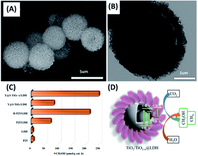 |
| | Fig. 8 (A and B) SEM and TEM images of Y@S– TiO2−x/LDH. (C) Comparative results of CO2 reduction in terms of CH3OH production under visible light illumination. (D) Plausible charge transfer mechanism for superior photocatalytic efficiency of Y@S–TiO2−x/LDH toward CO2 reduction. Reproduced with permission from ref. 98. Copyright 2019, American Chemical Society. | |
3.4 H2 production
H2 production on semiconductor photocatalysts from water splitting represents a viable, green approach to creation of alternative energy. Ever since Fujishima and Honda demonstrated water photolysis on TiO2 photoelectrodes,99 photocatalytic H2 production has been an ultimate goal of solar energy conversion in the search for clean energy. There are many strategies developed to enhance the efficiency of solar H2 production. Employing unique nanostructures to better harvest solar energy is particularly important because light absorption is the leading process determining how many charge carriers can be produced. In this regard, yolk–shell nanostructures offer an ideal structural platform since light harvesting efficiency can be enhanced as a result of multi-reflection of incident light within the void space. Till now, a variety of yolk–shell nanostructures have demonstrated remarkable activity of photocatalytic H2 production, such as Au–TiO2100,101 and Au–CdS.63,102
Shi et al. prepared for Au–TiO2 yolk–shell nanospheres with a chemical etching method.100 These nanospheres were assembled into three-dimensional arrays (3D-array) to study the multi-scattering effect on the photocatalytic activity of H2 production. Fig. 9A depicts the charge transfer mechanism for Au–TiO2. The plasmonic Au yolk can be excited by visible light, generating hot electrons for enhancing the photoactivity of TiO2. As Fig. 9B shows, the as-prepared Au–TiO2 was highly mono-dispersed with a uniform shell thickness of 46 nm and inner cavity size of 176 nm. The SEM image in Fig. 9C clearly reveals the orderly packed, hexagonal structure for 3D-array. These arrays comprised several layers of Au–TiO2, which may facilitate light scattering between the individual Au–TiO2 spheres. Fig. 9D compares the photocatalytic activity of H2 production among three relevant samples. Compared with hollow TiO2, both 3D-array and non-assembled Au–TiO2 showed much higher activity of H2 production, manifesting the beneficial function of the plasmonic Au. Significantly, 3D-array showed 1.4 folds higher activity than non-assembled Au–TiO2. As Fig. 9E illustrates, the superior activity of 3D-array can be attributed to the improved photon harvesting resulting from the multi-scattering of incident light between the individual Au–TiO2. On the other hand, photon harvesting can also be augmented in each of the yolk–shell particles because incident light can be reflected many times within the void space. As a result of the increased light refection inside the TiO2 shell, the plasmonic Au yolk can generate more hot electrons for improving the photocatalytic activity. The superior photocatalytic performance of yolk–shell nanostructures toward H2 production can be reflected from the unprecedented AQY value. In Chiu's work,63 Au–CdS yolk–shell nanostructures achieved an AQY value of 4.22% at 420 nm without the use of Pt co-catalysts. This value was substantially larger than that of Pt-deposited Au–CdS core–shell nanostructures (1.9%),103 highlighting the great promise of yolk–shell nanostructures for photocatalytic H2 production.
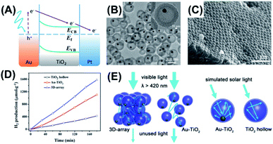 |
| | Fig. 9 (A) Plausible charge transfer mechanism for superior photocatalytic efficiency of Au–TiO2 toward H2 production, (B) TEM image of Au–TiO2, (C) SEM image of 3D-array, (D) comparative results of H2 production under simulated daylight illumination, (E) schematic illustration of multi-scattering effect and increased light reflection for 3D-array and Au–TiO2. Reproduced with permission from ref. 100. Copyright 2016, ACS publications. | |
3.5 O2 production
Compared to H2 production, there are relatively few kinds of photocatalysts that exhibit valid activity of O2 production from water splitting. The cause is the higher kinetics difficulty of water oxidation, which requires four equivalent holes in order to produce an O2 molecule. Despite the difficulty, O2 production is still an important reaction with regard to the realization of overall water splitting. The use of yolk–shell nanostructures for conducting photocatalytic O2 production is quite limited. The successful example was demonstrated on Fe2TiO5–TiO2.104
Among the different semiconductor photocatalysts, TiO2 and α-Fe2O3 are particularly suited for conducting photocatalytic O2 production by virtue of the sufficiently anodic VB level (EVB = +2.91 eV vs. NHE for TiO2; EVB = +2.48 eV vs. NHE for α-Fe2O3). Waqas et al. prepared for Fe2TiO5–TiO2 yolk–shell hollow spheres (FTYS-HS) with a thermal treatment method and demonstrated effective photocatalytic O2 production.104 Here, Fe2TiO5 has a band structure straddling that of TiO2 and α-Fe2O3. By combining Fe2TiO5 with TiO2, the photocatalytic O2 production efficiency can be enhanced as a result of the improved charge transfer.105 Fig. 10A shows the high-angle annular dark-field (HAADF) scanning TEM image and the corresponding energy-dispersive spectrometry (EDS) mapping data for FTYS-HS, which revealed uniform distribution of Ti and Fe at the yolk and shell regions. Fig. 10B compares the photocatalytic activity of O2 production among four relevant samples. As expected, FTYS-HS achieved a much higher activity of O2 production than P25, rutile TiO2 hollow spheres (rutile HS), and Fe2TiO5 hollow spheres (Fe2TiO5 HS). The superiority of FTYS-HS can be partly assigned to Fe2TiO5/TiO2 heterojunction which improved charge carrier separation.106 The multi-reflection of incident light inside the yolk–shell structures contributed to the enhanced photocatalytic activity of FTYS-HS as well. Similar to the case of CO2 reduction, only a limited number of examples have demonstrated the practice of yolk–shell nanostructures in photocatalytic O2 production. Future effort can be focused on the survey of more yolk–shell nanostructures candidates to construct photocatalytic systems for efficient O2 production.
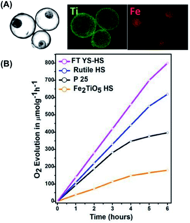 |
| | Fig. 10 (A) HAADF scanning TEM image and the corresponding EDS data of FTYS-HS, (B) comparative results of O2 production under white light illumination. Reproduced with permission from ref. 104. Copyright 2017, Elsevier. | |
3.6 Fine chemicals synthesis
Fine chemicals synthesis by means of photocatalytic redox reactions is a prosperous topic attracting interdisciplinary scientists. Traditionally, fine chemicals are manufactured under harsh conditions, such as high temperature and highly oxidative environment. Although high yield with a good selectivity can be achieved, the traditional approach is costly and harmful, and therefore, is not viable from the economic and environmental points of view. As an alternate, using photocatalysts to synthesize fine chemicals has received increasing attention. Examples include the production of aldehydes by photocatalytic oxidation107–110 and the generation of amines by photocatalytic reduction.111–114 Yolk–shell nanostructures have also demonstrated remarkable photocatalytic activity for synthesis of fine chemicals.115–120
In a study by Ziarati et al., yolk–shell TiO2 structures (Y@S–TiO2) were prepared in a solvothermal reaction via Ostwald ripening.118 The obtained Y@S–TiO2 was further modified with di-amines to wrap graphene sheets in a high level. The resultant graphene highly wrapped yolk–shell TiO2 (G-HW-Y@S–TiO2) architectures showed good selectivity of producing aldehydes in the photocatalytic oxidation of aromatic alcohols. Fig. 11A–C show the SEM and TEM images for G-HW-Y@S–TiO2. Successful wrapping of 5 nm-thick graphene sheets can be recognized. In Fig. 11D, the photocatalytic efficiency of G-HW-Y@S–TiO2 toward selective oxidation of benzyl alcohol was investigated and compared with other counterpart samples, including graphene wrapped TiO2 (G-W-TiO2), graphene wrapped hollow TiO2 (G-W-H-TiO2) and graphene lightly wrapped yolk–shell TiO2 (G-W-Y@S–TiO2). G-W-TiO2 showed mediocre activity with a moderate conversion rate (47%) and benzaldehyde selectivity (61%). For G-W-H-TiO2, the conversion rate (78%) and selectivity (94%) can be largely increased. Significantly, G-W-Y@S–TiO2 and G-HW-Y@S–TiO2 showed nearly 100% of benzaldehyde selectivity, with G-HW-Y@S–TiO2 exhibiting a little bit higher conversion. The superior performance of G-HW-Y@S–TiO2 for selective oxidation of benzyl alcohol can be attributed to the synergy among several factors. Note that graphene had a work function (4.42 eV) larger than TiO2 (4.21 eV).121 The photoexcited electrons of TiO2 were then transferred to graphene, leaving photoexcited holes at TiO2. Therefore, the photocatalytic oxidation reaction mostly occurred at the TiO2 surface of G-HW-Y@S–TiO2. As illustrated in Fig. 11E, the hydrophilic alcohol reactant first diffused through the mesoporous shell, reacted with the photoexcited holes at TiO2 yolk, and produced benzyl alcohol cation radicals. At the same time, the photoexcited electrons at graphene reacted with the dissolved O2 and generated ˙O2−. The cation radicals further reacted with ˙O2− and produced benzaldehydes. Such a partially oxidized product was hydrophobic, which can be repulsed by the hydrophilic surface of TiO2 and would thus diffuse outward prior to further oxidation. The wrapped graphene sheets on the other hand can prevent the effluent benzaldehydes from direct contact with TiO2, prohibiting them from being oxidized by the photoexcited holes at TiO2. This explained why such a high selectivity can be achieved on G-HW-Y@S–TiO2.
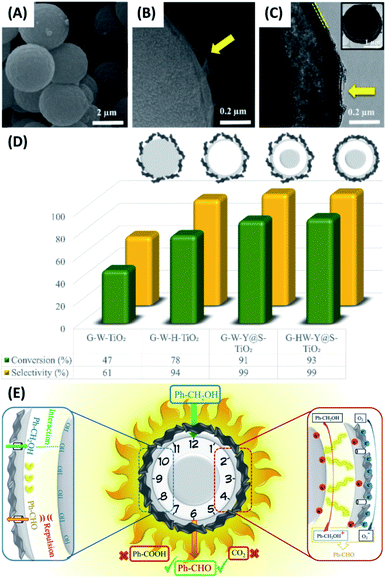 |
| | Fig. 11 (A–C) SEM and TEM images of G-HW-Y@S–TiO2. (D) Comparative results of selective benzyl alcohol oxidation under visible light illumination. (E) Plausible charge transfer mechanism for superior photocatalytic activity of G-HW-Y@S–TiO2 toward selective benzyl alcohol oxidation. Reproduced with permission from ref. 118. Copyright 2018, Elsevier. | |
Since the pioneering work published by Akira Suzuki in 1979,122 Suzuki–Miyaura coupling reaction has been widely utilized to synthesize a variety of technologically important organic molecules, such as styrenes and biphenyls. Typical Suzuki–Miyaura coupling reactions use Pd as catalysts. Photocatalysts containing Pd are also capable of conducting efficient coupling reactions119,123–125 In the study by Rohani et al.,128 yolk–shell structures comprising hydrogenated urchin-like TiO2 shell and TiO2 yolk (HUY@S-TOH) were prepared in an Ostwald ripening-based dissolution–recrystallization process. These yolk–shell structures were decorated with Au–Pd core–shell particles (HUY@S-TOH/AuPd), which were employed as photocatalysts to carry out Suzuki–Miyaura coupling reaction. In Fig. 12A and B, the TEM images clearly revealed the yolk–shell feature of HUY@S-TOH and the successful decoration of 5 nm-sized Au/Pd particles. The photocatalytic efficiency was studied by carrying out coupling reaction of 4-iodotoluene with phenylboronic acid under visible light illumination. The expected product was biphenyls. Four relevant samples, including P25 TiO2, P25/AuPd, Y@S-TO/AuPd, HUY@S-TOH/Au, HUY@S-TOH/Pd and HUY@S-TOH/AuPd, were tested and compared. Notably, P25 TiO2 showed negligible activity, while P25/AuPd was significantly active. This finding pointed out the necessity of using Au/Pd particles to conduct Suzuki–Miyaura coupling reaction. On the other hand, because of the higher surface area and enhanced photon harvesting inside the yolk–shell structures, Y@S-TO/AuPd showed much higher activity than P25/AuPd did. Among the different samples, HUY@S-TOH/AuPd showed the best activity in terms of biphenyls yield with a turnover frequency (TOF) of 7095 h−1. As summarized in Fig. 12C, this TOF value was considerably higher than the performance of the state-of-the-art photocatalysts ever reported. Fig. 12D further depicts the charge transfer mechanism accountable for the superior activity of HUY@S-TOH/AuPd. Hydrogenated TiO2 was capable of harvesting visible photons to equip TiO2 with visible photoactivity. Upon visible irradiation, the photoexcited electrons of hydrogenated TiO2 may transfer to Au/Pd; meanwhile, hot electrons induced by plasmonic absorption of Au were injected to Pd. The C–X bonding of aryl halides can then be activated by the electron-enriched Pd, facilitating oxidative addition process of Suzuki reaction.126 In the meantime, phenylboronic acid could be oxidized by photoexcited holes. Cross-coupling reaction then took place as the oxidized phenylboronic acids encountered the activated aryl halides, producing the expected product.
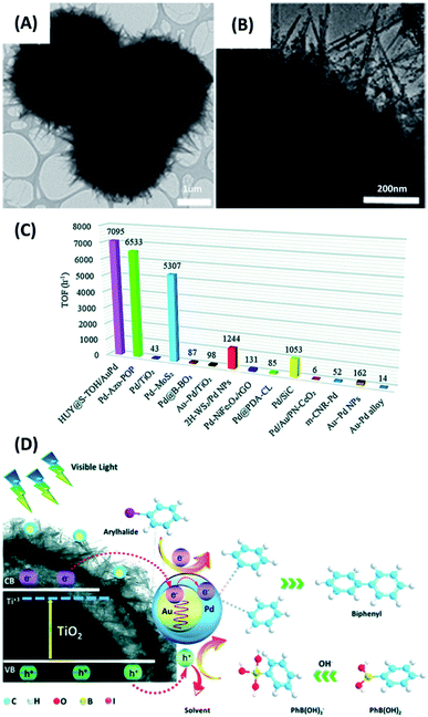 |
| | Fig. 12 (A and B) TEM images of HUY@S-TOH/AuPd. (C) Comparison of TOF value with those achieved by state-of-the-art photocatalysts reported in the literature. (D) Plausible charge transfer mechanism for superior photocatalytic activity of HUY@S-TOH/AuPd toward Suzuki–Miyaura coupling reaction. Reproduced with permission from ref. 119. Copyright 2019, Royal Society of Chemistry. | |
4. Interfacial charge dynamics
The efficiency of semiconductor photocatalysts is dependent on intrinsic properties, including light absorption, carrier transfer and recombination, and kinetics of surface redox reactions. The capability of light absorption inherits from the optical properties of the chosen photocatalysts, which can be augmented by means of dopant introduction and materials combination. Charge dynamics at interface dictates charge transfer and carrier utilization, the two determinant processes involved in the photocatalytic reactions. Under light illumination, the photoexcited electrons and holes are transported from the bulk of the photocatalysts to the surface region for conducting redox reactions. These charge carriers are however inclined to be trapped and recombined before they can eventually reach surface region. This would jeopardize carrier utilization efficiency and decrease the photocatalytic performance, making interfacial charge dynamics the most critical factor determining the overall photocatalytic efficiency. An in-depth understanding of how photoexcited charge carriers can be transported, trapped and/or recombined will enable performance optimization of semiconductor photocatalysts. In particular, establishing correlations between interfacial charge dynamics and photocatalytic activity can offer empirical yet practicable knowledge for devising versatile nanostructures for superior photocatalytic applications.
Compared to the extensive studies of interfacial charge dynamics on composite nanostructures like particle-decorated nanostructures19–21,23–29,31–40 and core–shell nanocrystals,43,45–47 examples are relatively scarce for the topic of studying charge dynamics on yolk–shell nanostructures.63,81,101,102,127,128 In this section, we introduce two representative studies that explored the correlations of interfacial charge dynamics with the photocatalytic performance of H2 production on yolk–shell nanostructures (Au–CdS63 and Au–TiO2![[thin space (1/6-em)]](https://www.rsc.org/images/entities/char_2009.gif) 101). In addition to realization of charge dynamics, manipulation of charge transfer behaviors is also imperative with regard to the regulation of photocatalytic reactions. For yolk–shell nanostructures, spatial separation of photoexcited electrons and holes at the yolk and shell region is possible since the yolk is inherently separated from the shell. The spatial separation of electrons and holes not only guarantees long-lived charge separation but also inhibits backward reactions, both of which are crucial for reinforcing the utility in photocatalytic reactions. This concept has not been realized on yolk–shell nanostructures, but it has been widely demonstrated on hollow nanostructures, a structurally analogous example to yolk–shell model. Additional focus on the strategies of achieving spatial separation of charge carriers for hollow nanostructures will be placed in this section with the aim to provide applicable guidelines to yolks-shell nanostructures.
101). In addition to realization of charge dynamics, manipulation of charge transfer behaviors is also imperative with regard to the regulation of photocatalytic reactions. For yolk–shell nanostructures, spatial separation of photoexcited electrons and holes at the yolk and shell region is possible since the yolk is inherently separated from the shell. The spatial separation of electrons and holes not only guarantees long-lived charge separation but also inhibits backward reactions, both of which are crucial for reinforcing the utility in photocatalytic reactions. This concept has not been realized on yolk–shell nanostructures, but it has been widely demonstrated on hollow nanostructures, a structurally analogous example to yolk–shell model. Additional focus on the strategies of achieving spatial separation of charge carriers for hollow nanostructures will be placed in this section with the aim to provide applicable guidelines to yolks-shell nanostructures.
4.1 Charge dynamics of Au–CdS
In Chiu's study,63 transient absorption (TA) spectroscopy was utilized to explore charge transfer dynamics of Au–CdS nanostructures. A definite correlation of interfacial charge dynamics and photocatalytic efficiency with the void size of Au–CdS was established. Note that TA is a powerful ultrafast laser spectroscopic technique used to monitor the electronic transition processes of photoexcited charge carriers within semiconductor nanostructures. By identifying the photophysics beyond the recorded TA spectra, the interfacial charge dynamics of the samples can be clearly interpreted.
Fig. 13A and B show the TA spectra for pure hollow CdS and Au–CdS-4 recorded by increasing delay times from −2 to 100 ps at the probe wavelength between 450 to 750 nm. For pure CdS, a narrow negative bleaching was notices at 475 nm, which can be ascribed to the typical ground state bleaching of charge carriers from the excited CdS. This transient bleaching was however red-shifted to 515 nm for Au–CdS-4, reflecting pronounced electronic interaction between Au yolk and CdS shell. Most importantly, Au–CdS-4 showed much quicker decay of transient bleaching than pure CdS, suggesting the prevalence of additional electron transportation pathway from CdS to Au. Fig. 13C further compares the decay kinetics of TA bleaching for pure CdS and the four CdS–Au samples. Here, a counterpart sample by physically mixing pure CdS and Au NPs (denoted as CdS + Au) was also examined in order to highlight the superior feature of yolk–shell nanostructures. These TA profiles were fitted with a biexponential function to obtain the quantitative information of charge dynamics. Two lifetime components (τ1 and τ1) can be generated from the fitting, which was respectively associated with exciton decay processes induced by shallow and deep traps of CdS. To offer a global comparison, an intensity-weighted average lifetime, <τ>, was presented, respectively giving 27.44 ps, 24.74 ps, 14.66 ps, 13.79 ps, 12.34 ps, and 11.71 ps for pure CdS, CdS + Au, Au–CdS-1, Au–CdS-2, Au–CdS-3, and Au–CdS-4. By considering that electron transportation from CdS to Au caused the reduced lifetime of Au–CdS, the rate constant of interfacial charge transfer (kct) can be obtained using the equation
| kct (CdS → Au) = 1/<τ> (Au–CdS) − 1/<τ> (pure CdS) |
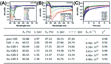 |
| | Fig. 13 (A and B) TA profiles of pure CdS and Au–CdS-4. (C) Kinetics of TA bleaching for relevant samples. Inserted table summarizes the fitting results. Reproduced with permission from ref. 63. Copyright 2019, Elsevier. | |
The calculated kct value was respectively 0.40 × 10¹⁰ s−1, 3.18 × 10¹⁰ s−1, 3.61 × 10¹⁰ s−1, 4.46 × 10¹⁰ s−1, and 4.90 × 10¹⁰ s−1 for CdS + Au, Au–CdS-1, Au–CdS-2, Au–CdS-3, and Au–CdS-4. There were two significant points to highlight. Firstly, compared to CdS + Au, the four Au–CdS samples all exhibited larger kct, signifying more efficient charge dynamics within the yolk–shell structure. Secondly, the kct of Au–CdS was enhanced as void size increased, suggesting that void size was a vital cause influencing charge transfer from CdS to Au. The implications of these two features in photocatalytic reactions were further explored. The comparative results of photocatalytic H2 production showed consistency with the variation of kct, in which the four Au–CdS surpassed CdS + Au and CdS–Au-4 had the highest activity. This work highlighted the importance of understanding charge dynamics of yolk–shell nanostructures toward the optimization of photocatalytic performance.
4.2 Charge dynamics of Au–TiO2
In Dillon's work,101 Au–TiO2 yolk–shell nanostructures with gradually improved shell crystallinity were prepared. The influence of shell crystallinity on the photophysics and its correlation with the resultant photocatalytic performance was investigated. In this study, time-resolved photoluminescence (PL) was employed to follow the dynamics of the photoexcited electrons and holes. Compared to TA, time-resolved PL offers a more intuitive viewpoint to explore the crystallinity effect on charge dynamics because PL emissions are highly sensitive to the crystallographic structure.129–131
Fig. 14A and B displays the time-resolved PL spectra recorded at 500 nm after 266 nm laser excitation at two time regimes (1 ns and 20 ns). Four Au–TiO2 samples were compared, including the least crystalline sample A and the most crystalline sample D. Here, the emissions at 500 nm can be associated with charge recombination involving self-trapped excitons of TiO2 or surface defects within TiO2 lattice. The dynamics of this emission can thus reflect the degree of crystallinity of TiO2. At both time regimes, sample D showed considerably slower PL decay kinetics than sample A did, suggesting that better crystallinity may lead to slower charge recombination as a result of the smaller number of defect sites. These kinetics profiles can be analyzed using a stretched exponential model, from which a characteristic lifetime was received. At 20 ns time regime, the computed lifetime of sample A, B, C, D was respectively 0.084 ns, 0.10 ns, 0.23 ns, 0.31 ns. The correspondence between charge dynamics and crystallinity degree was further correlated with the photocatalytic activity of H2 production. In Fig. 14C, a clear correlation of PL lifetime with H2 production rate was found. This correlation demonstrated that high degree of crystallinity was conducive to an enhanced photocatalytic activity for Au–TiO2 as the number of defect sites may be reduced. This work also illustrated the promise of employing time-resolved PL to evaluate the photocatalytic performance of yolk–shell nanostructures.
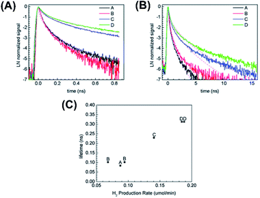 |
| | Fig. 14 (A and B) Time-resolved PL spectra of four Au–TiO2 samples recorded at two time regimes. (C) Correlation of PL lifetime and H2 production rate with the crystallinity of Au–TiO2. Reproduced with permission from ref. 101. Copyright 2013, Royal Society of Chemistry. | |
4.3 Spatial separation of charge carriers
The concept of spatially separating photoexcited electrons and holes stems from the introduction of co-catalysts that have been widely employed to reduce the overpotentials of photocatalytic reactions. There are two types of co-catalysts used in photocatalysis; one functions as an electron trap site due to its large work function, such as Pt, Ag, Au particles (also known as reduction co-catalysts),86,120,132,133 and the other one serves as a hole trap site, such as IrO2, PbOx, PbS, MnOx, CoOx (also known as oxidation co-catalysts).120,133–138 The introduction of co-catalysts can anchor electrons or holes to guarantee long-lived charge separation.120,123,125,133 Significantly, simultaneous loading of dual co-catalysts makes possible the spatial separation of electrons from holes, which can be utilized to achieve the concurrent occurrence of redox reactions at different sites. However, random deposition of dual co-catalysts may lead to the interference of redox reactions, arousing charge recombination and backward reactions to deteriorate the overall photocatalytic efficiency. Therefore, introducing dual co-catalysts at separate sites of photocatalysts is indispensable to achieving spatial separation of charge carriers.
The introduction of dual co-catalysts at separate sites has been realized on solid nanostructures with well-defined exposed facets, in which site-selective deposition of co-catalysts can be accomplished via photo-deposition.133 For yolk–shell and hollow nanostructures which inherently have two separate sites, i.e. the inner and outer surfaces, selective deposition of dual co-catalysts at these surfaces can be more readily achieved. Domen's group demonstrated a successful practice of spatially selective deposition of dual co-catalysts on Ta3N5 hollow spheres, in which reduction (Pt) and oxidation (IrO2) co-catalyst was respectively loaded at the inner and outer surface.134 Upon light irradiation, the photoexcited electrons were attracted by Pt, while the photogenerated holes were trapped by IrO2. As a result of the spatial separation of electrons and holes, charge recombination was greatly restrained, leading to a much enhanced photocatalytic activity of overall water splitting. In Zheng's work, hollow C3N4 structures were simultaneously deposited with Pt and Co3O4 co-catalysts to demonstrate the effectiveness of photocatalytic overall water splitting.138 The spatial separation of Pt (at inner surface of C3N4) from Co3O4 (at outer surface of C3N4) not only improved charge separation, but also inhibited the further reduction of O2 at Pt. As Fig. 15 compares, a stoichiometric ratio of the produced H2 to O2 can be attained as Pt and Co3O4 were separately loaded on C3N4. If Pt and Co3O4 were both deposited at the outer surface of C3N4, a decrease in overall water slitting activity accompanied by reduced O2 production otherwise resulted.
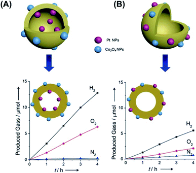 |
| | Fig. 15 Comparative results of photocatalytic water splitting under UV illumination on C3N4 hollow structures with (A) spatially separate co-catalysts and (B) randomly distributed co-catalysts. Reproduced with permission from ref. 138. Copyright 2016, Wiley. | |
It should be noted that the dispersion and size of the loaded co-catalysts pose significant effect on the photocatalytic efficiency. Poor dispersion and uneven size distribution of co-catalysts can cause significant particle aggregation, reducing long-term stability to deteriorate the practice of photocatalysis. Devising a versatile synthetic procedure capable of depositing co-catalysts with good dispersion and uniform size is important to ensure the sustainable operation of photocatalysts. For yolk–shell and hollow nanostructures, it is difficult to control the dispersion and size of the deposited co-catalysts at inner surface, especially when the initial template or the resulting shell contains irregular porosity.139 She et al.137 and Sun et al.139 employed zeolites with ordered micropores as a structurally confined template to allow for the loading of well-dispersed co-catalysts at the inner surface of hollow nanostructures. As displayed in Fig. 16, the nanoconfinement effect of zeolites enabled a fine tunability of dispersion, size and amount for the loaded MOx (M = Pd, Co, Ni or Cu).137 Further external growth of TiO2 followed by the removal of zeolites resulted in the formation of TiO2 hollow nanostructures with MOx exactly deposited at the inner surface. The outer photo-deposited Pt can then be divided from the inner MnOx by TiO2, achieving great spatial separation for the dual co-catalysts to show remarkable photocatalytic activity. On the other hand, atomic layer deposition (ALD) also offers feasibility for deposition of highly-dispersed co-catalysts at the selected positions. Zhang et al. employed ALD to sequentially deposit Pt nanoclusters and TiO2 layer on carbon nanocoil (CNC) template.135 Upon a removal of CNC, porous TiO2 nanotubes with Pt deposited at the inner surface were obtained. Further ALD deposition of CoOx produced TiO2 nanotubes with Pt and CoOx respectively loaded at the inner and outer surfaces. The amount and location of the loaded Pt and CoOx can be finely controlled by adjusting ALD conditions, proven to be crucial for interfacial charge dynamics and determinant to the resultant photocatalytic activity.
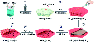 |
| | Fig. 16 Schematic illustration of using zeolites as structurally confined template to achieve spatial separation of dual co-catalysts on TiO2. Reproduced with permission from ref. 137. Copyright 2020, American Chemical Society. | |
Despite extensive efforts, it has been pointed out that the spatially separated co-catalysts can only enhance charge separation at surface and are not efficient for promoting charge separation in bulk. To address this issue, Li et al. prepare for TiO2/In2O3 mesoporous hollow spheres and selectively deposited Pt and MnOx at the inner and outer surface.140 As illustrated in Fig. 17A and B, the idea was to combine the advantages of TiO2/In2O3 as thin heterojunction, and Pt and MnOx as spatially separated co-catalysts. Here, the thin heterojunction (overall thickness = 20 nm) can promote effective charge separation in the whole bulk region as the nominal diffusion path of charge carriers is comparable to the heterojunction thickness. The separated charge carriers can then be transported in an opposite direction to the surface region, where the electrons and holes were respectively trapped by Pt and MnOx. With this synergy, much enhanced photocatalytic activity of O2 production can be attained. Such a regulation of charge separation in the bulk can be evidenced by studying charge dynamics of the samples as they were placed in an environment containing electron and hole scavengers. Under this situation, charge dynamics of the samples can be dictated by bulk recombination. The resultant time-resolved PL data suggested that bulk recombination was indeed prohibited by the introduction of thin heterojunction. Likewise, Wang et al. proposed a thin heterojunction based on TiO2/CdS hollow spheres (overall thickness = 23 nm) and loaded Pt and Co3O4 at the inner and outer surface, respectively.136 As Fig. 17C and D illustrates, the synergy of thin heterojunction and spatially separated co-catalysts gave rise to a remarkable enhancement in the performance of solar H2 production.
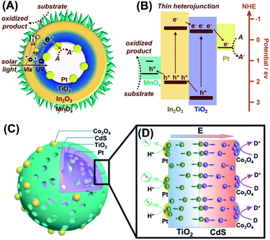 |
| | Fig. 17 (A) Microstructural model for TiO2/In2O3 hollow spheres with Pt and MnOx respectively deposited at the inner and outer surface. (B) Plausible charge transfer mechanism for superior photocatalytic activity of Pt/TiO2/In2O3/MnOx. Reproduced from ref. 140. Copyright 2016, Wiley. (C) Microstructural model for TiO2/CdS hollow spheres with Pt and Co3O4 respectively deposited at the inner and outer surface. (D) Plausible charge transfer mechanism for superior photocatalytic activity of Pt/TiO2/In2O3/Co3O4. Reproduced with permission from ref. 136. Copyright 2016, Wiley. | |
5. Conclusions and future perspective
In this review, the synthetic schemes for yolk–shell nanostructures are systematically organized. The formation of hollow shell can be attributed to the difference in solubility product for Kirkendall effect and the difference in redox potential for galvanic replacement. By pairing up materials with appropriate solubility products and redox potentials, yolk–shell nanostructures composed of various components can be readily obtained. Ostwald ripening takes the advantage of the dissolution-re-deposition principle during the process of crystal growth. The shell layer grows as the core particles dissolve, or the shell layer (or core particle) itself dissolves and re-crystallizes, both of which generate empty space between the core and shell as a result of the contraction of the dissolved components. Both chemical etching and thermal treatment are based on the assistance of sacrificial templates like SiO2 and carbon. Upon a removal of the templates, cavity inside the shell can evolve. The necessity of removing templates by strong acids/bases or high-temperature calcination however poses significant concerns on whether or not the remaining components will be deteriorated in such a harsh condition. Definitely, yolk–shell nanostructures with tunable structural parameters are essential for further tailoring and optimizing the intrinsic properties. Despite extensive synthetic efforts, it is difficult to achieve exact control over the size of void space and thickness of encircling shell because void formation and shell growth proceed simultaneously in most cases. Continuous efforts must be made to manipulate the growth of hollow shell and obtain yolk–shell nanostructures with controllable void size and shell thickness.
Compared to the structurally analogous counterpart, i.e. core–shell nanostructures, yolk–shell nanostructures have exceptional structural features that can be exploited to tailor the photocatalytic properties. For example, the movable yolk particles can stir the reaction solution inside the void space, creating a homogeneous reaction environment for accelerating mass transfer kinetics and thus enhancing the photocatalytic activity. An in-depth understanding of mass transfer kinetics across the shell can lay the foundation for constructing robust nanoreactors based on yolk–shell nanostructures. In terms of charge carrier transfer, a small number of studies are available on deriving the correlations of interfacial charge dynamics with the photocatalytic performance for yolk–shell nanostructures. The charge transfer between the yolk and the shell and its influence on the photocatalytic properties has seldom been examined. In particular, the movable yolk can cause ambiguous interpretation of charge transfer dynamics. Because the yolk particles are constantly moving during the photocatalytic process, complicated charge transfer and separation behaviors are expected. How to devise a realistic charge transfer mechanism by considering the influence of movable yolk is another focus of future direction. One future scenario of using yolk–shell nanostructures for advanced photocatalytic applications is spreading their powder into a polluted pond or river for environmental remediation. The empty space in the hollow shell enables yolk–shell nanostructures to float on water, providing high adaptability and recyclability for their participation in photocatalytic processes. On the other hand, spatial separation of photoexcited electrons and holes at the yolk and shell region is achievable for yolk–shell nanostructures. These separated charge carries can be more easily and separately accessible by the reactive species, allowing for the concurrent yet separate occurrence of reduction and oxidation reactions. This achievement is particularly appealing to overall water splitting and CO2 reduction, the scenario of which can better operate as the redox reactions occur at different sites. It is thus not surprising to witness the realization of artificial photosynthesis by utilizing yolk–shell nanostructures. These demonstrations are not yet fully comprehended, requiring further efforts to make significant breakthrough.
Conflicts of interest
There are no conflicts to declare.
Acknowledgements
This work was financially supported by the Ministry of Science and Technology (MOST) of Taiwan under grants MOST 108-2628-M-009-004-MY3, MOST 108-2218-E-009-039-MY3 and MOST 109-2923-M-009-003-MY2, and the National Research Foundation of Korea under grant NRF-2019K2A9A1A06102672. Y.-J. H. also acknowledges the budget support from the Center for Emergent Functional Matter Science of National Chiao Tung University from The Featured Areas Research Center Program within the framework of the Higher Education Sprout Project by the Ministry of Education in Taiwan.
References
- R.-B. Wei, Z.-L. Huang, G.-H. Gu, Z. Wang, L. X. Zeng, Y. B. Chen and Z.-Q. Liu, Appl. Catal., B, 2018, 231, 101–107 CrossRef CAS.
- R. Shi, H.-F. Ye, F. Liang, Z. Wang, K. Li, Y. X. Weng, Z. S. Lin, W.-F. Fu, C.-M. Che and Y. Chen, Adv. Mater., 2018, 30, 1705941 CrossRef PubMed.
- S. W. Cao, B. J. Shen, T. Tong, J. W. Fu and J. G. Yu, Adv. Funct. Mater., 2018, 28, 1800136 CrossRef.
- S. B. Wang, B. Y. Guan and X. W. D. Lou, J. Am. Chem. Soc., 2018, 140, 5037–5040 CrossRef CAS PubMed.
- C. Y. Zhou, C. Lai, D. L. Huang, G. M. Zeng, C. Zhang, M. Cheng, L. Hu, J. Wan, W. P. Xiong, M. Wen, X. F. Wen and L. Qin, Appl. Catal., B, 2018, 220, 202–210 CrossRef CAS.
- X.-J. Wen, C.-G. Niu, L. Zhang, C. Liang, H. Guo and G.-M. Zeng, J. Catal., 2018, 358, 141–154 CrossRef CAS.
- Q. Wang, W. Wang, L. L. Zhong, D. M. Liu, X. Z. Cao and F. Y. Cui, Appl. Catal., B, 2018, 220, 290–302 CrossRef CAS.
- Y. Yang, Z. T. Zeng, C. Zhang, D. L. Huang, G. M. Zeng, R. Xiao, C. Lai, C. Y. Zhou, H. Guo, W. J. Xue, M. Cheng, W. J. Wang and J. J. Wang, Chem. Eng. J., 2018, 349, 808–821 CrossRef CAS.
- M. Barbero and S. Dughera, Org. Biomol. Chem., 2018, 16, 295–301 RSC.
- S. Xu, P. Zhou, Z. Zhang, C. Yang, B. Zhang, K. Deng, S. Bottle and H. Zhu, J. Am. Chem. Soc., 2017, 139, 14775–14782 CrossRef CAS.
- W.-Y. Cheng, W.-T. Chen, Y.-J. Hsu and S.-Y. Lu, J. Phys. Chem. C, 2009, 113(40), 17342–17346 CrossRef CAS.
- A. T. Nguyen, W.-H. Lin, Y.-H. Lu, Y.-D. Chiou and Y.-J. Hsu, Appl. Catal., A, 2014, 476, 140–147 CrossRef CAS.
- Y.-H. Lu, W.-H. Lin, C.-Y. Yang, Y.-H. Chiu, Y.-C. Pu, M.-H. Lee, Y.-C. Tseng and Y.-J. Hsu, Nanoscale, 2014, 6, 8796–8803 RSC.
- Y.-H. Chiu, T.-H. Lai, C.-Y. Chen, P.-Y. Hsieh, K. Ozasa, M. Niinomi, K. Okada, T.-F. M. Chang, N. Matsushita, M. Sone and Y.-J. Hsu, ACS Appl. Mater. Interfaces, 2018, 10(27), 22997–23008 CrossRef CAS PubMed.
- K.-A. Tsai, P.-Y. Hsieh, T.-H. Lai, C.-W. Tsao, H. Pan, Y.-G. Lin and Y.-J. Hsu, ACS Appl. Energy Mater., 2020, 3, 5322–5332 CrossRef CAS.
- P.-Y. Hsieh, T. Kameyama, T. Takiyama, K. Masuoka, T. Yamamoto, Y.-J. Hsu and T. Torimoto, J. Mater. Chem. A, 2020, 8, 13142–13149 RSC.
- Y.-C. Pu, Y.-C. Chen and Y.-J. Hsu, Appl. Catal., B, 2010, 97, 389–397 CrossRef CAS.
- W.-T. Chen and Y.-J. Hsu, Langmuir, 2010, 26, 5918–5925 CrossRef CAS PubMed.
- K.-H. Chen, Y.-C. Pu, K.-D. Chang, Y.-F. Liang, C.-M. Liu, J.-W. Yeh, H.-C. Shih and Y.-J. Hsu, J. Phys. Chem. C, 2012, 116, 19039–19045 CrossRef CAS.
- Y.-C. Chen, Y.-C. Pu and Y.-J. Hsu, J. Phys. Chem. C, 2012, 116, 2967–2975 CrossRef CAS.
- Y.-F. Lin and Y.-J. Hsu, Appl. Catal., B, 2013, 130–131, 93–98 CrossRef CAS.
- Y.-C. Pu, G. Wang, K.-D. Chang, Y. Ling, Y.-K. Lin, B. C. Fitzmorris, C.-M. Liu, X. Lu, Y. Tong, J. Z. Zhang, Y.-J. Hsu and Y. Li, Nano Lett., 2013, 13, 3817–3823 CrossRef CAS PubMed.
- M.-Y. Chen and Y.-J. Hsu, Nanoscale, 2013, 5, 363–368 RSC.
- Y.-C. Chen, K.-I. Katsumata, Y.-H. Chiu, K. Okada, N. Matsushita and Y.-J. Hsu, Appl. Catal., A, 2015, 490, 1–9 CrossRef CAS.
- K.-A. Tsai and Y.-J. Hsu, Appl. Catal., B, 2015, 164, 271–278 CrossRef CAS.
- Y.-C. Pu, W.-H. Lin and Y.-J. Hsu, Appl. Catal., B, 2015, 163, 343–351 CrossRef CAS.
- Y.-C. Chen, T.-C. Liu and Y.-J. Hsu, ACS Appl. Mater. Interfaces, 2015, 7, 1616–1623 CrossRef CAS PubMed.
- Y.-H. Hsu, A. T. Nguyen, Y.-H. Chiu, J.-M. Li and Y.-J. Hsu, Appl. Catal., B, 2016, 185, 133–140 CrossRef CAS.
- W.-H. Lin, Y.-H. Chiu, P.-W. Shao and Y.-J. Hsu, ACS Appl. Mater. Interfaces, 2016, 8, 32754–32763 CrossRef CAS.
- T. H. Do, C. N. Van, K.-A. Tsai, L. T. Quynh, J.-W. Chen, Y.-C. Lin, Y.-C. Chen, W.-C. Chou, C.-L. Wu, Y.-J. Hsu and Y.-H. Chu, Nano Energy, 2016, 23, 153–160 CrossRef CAS.
- J.-M. Li, H.-Y. Cheng, Y.-H. Chiu and Y.-J. Hsu, Nanoscale, 2016, 8, 15720–15729 RSC.
- Y.-C. Pu, H.-Y. Chou, W.-S. Kuo, K.-H. Wei and Y.-J. Hsu, Appl. Catal., B, 2017, 204, 21–32 CrossRef CAS.
- Y.-H. Chiu and Y.-J. Hsu, Nano Energy, 2017, 31, 286–295 CrossRef CAS.
- Y.-S. Chang, M. Choi, M. Baek, P.-Y. Hsieh, K. Yong and Y.-J. Hsu, Appl. Catal., B, 2018, 225, 379–385 CrossRef CAS.
- J.-M. Li, C.-W. Tsao, M.-J. Fang, C.-C. Chen, C.-W. Liu and Y.-J. Hsu, ACS Appl. Nano Mater., 2018, 1, 6843–6853 CrossRef CAS.
- J.-M. Li, Y.-T. Wang and Y.-J. Hsu, Electrochim. Acta, 2018, 267, 141–149 CrossRef CAS.
- Y.-H. Chiu, K.-D. Chang and Y.-J. Hsu, J. Mater. Chem. A, 2018, 6, 4286–4296 RSC.
- P.-Y. Hsieh, Y.-H. Chiu, T.-H. Lai, M.-J. Fang, Y.-T. Wang and Y.-J. Hsu, ACS Appl. Mater. Interfaces, 2019, 11, 3006–3015 CrossRef CAS PubMed.
- Y.-S. Chang, P.-Y. Hsieh, T.-F. M. Chang, C.-Y. Chen, M. Sone and Y.-J. Hsu, J. Mater. Chem. A, 2020, 8, 13971–13979 RSC.
- W.-C. Hu, Y.-A. Chen, P.-Y. Hsieh, C.-W. Tsao, Y.-H. Chiu, T.-F. M. Chang, C.-Y. Chen, M. Sone and Y.-J. Hsu, J. Taiwan Inst. Chem. Eng., 2020, 112, 337–344 CrossRef CAS.
- A. Chauhan, M. Rastogi, P. Scheier, C. Bowen, R. Vasant Kumar and R. Vaish, Appl. Phys. Rev., 2018, 5, 041111 Search PubMed.
- W.-T. Chen, T.-T. Yang and Y.-J. Hsu, Chem. Mater., 2008, 20, 7204–7206 CrossRef CAS.
- T.-T. Yang, W.-T. Chen, Y.-J. Hsu, K.-H. Wei, T.-Y. Lin and T.-W. Lin, J. Phys. Chem. C, 2010, 114, 11414–11420 CrossRef CAS.
- W.-T. Chen, Y.-K. Lin, T.-T. Yang, Y.-C. Pu and Y.-J. Hsu, Chem. Commun., 2013, 49, 8486–8488 RSC.
- Y.-C. Pu, W.-T. Chen, M.-J. Fang, Y.-L. Chen, K.-A. Tsai, W.-H. Lin and Y.-J. Hsu, J. Mater. Chem. A, 2018, 6, 17503–17513 RSC.
- M.-Y. Kuo, C.-F. Hsiao, Y.-H. Chiu, T.-H. Lai, M.-J. Fang, J.-Y. Wu, J.-W. Chen, C.-L. Wu, K.-H. Wei, H.-C. Lin and Y.-J. Hsu, Appl. Catal., B, 2019, 242, 499–506 CrossRef CAS.
- Y.-H. Chiu, S. A. Lindley, C.-W. Tsao, M.-Y. Kuo, J. K. Cooper, Y.-J. Hsu and J. Z. Zhang, J. Phys. Chem. C, 2020, 124, 11333–11339 CrossRef CAS.
- A. Li, W. Zhu, C. Li, T. Wang and J. Gong, Chem. Soc. Rev., 2019, 48, 1874–1907 RSC.
- R. Purbia and S. Paria, Nanoscale, 2015, 7, 19789–19873 RSC.
- H. Wang, Q. Tang, Z. Chen, T. Li and J. Wang, Sci. China Mater., 2020, 63, 2189–2205 CrossRef CAS.
- C. Xia, H. Wang, J.-K. Kim and J. Wang, Adv. Funct. Mater., 2020, 2008247 Search PubMed.
- Q. Tang, Y. Ma and J. Wang, Sol. RRL, 2021, 5, 2000443 CrossRef CAS.
- Y.-H. Chiu, T.-F. M. Chang, C.-Y. Chen, M. Sone and Y.-J. Hsu, Catalysts, 2019, 9, 430 CrossRef CAS.
- Y.-H. Chiu, T.-H. Lai, M.-Y. Kuo, P.-Y. Hsieh and Y.-J. Hsu, APL Mater., 2019, 7, 080901 CrossRef.
- P.-Y. Hsieh, J.-Y. Wu, T.-F. M. Chang, C.-Y. Chen, M. Sone and Y.-J. Hsu, Arabian J. Chem., 2020, 13, 8372–8387 CrossRef CAS.
- M.-J. Fang, C.-W. Tsao and Y.-J. Hsu, J. Phys. D: Appl. Phys., 2020, 53, 143001 CrossRef CAS.
- T.-H. Lai, K.-I. Katsumata and Y.-J. Hsu, Nanophotonics, 2020, 10(2), 777–795 CrossRef.
- C.-W. Tsao, M.-J. Fang and Y.-J. Hsu, Coord. Chem. Rev., 2021, 438, 213876 CrossRef CAS.
- G. D. Park, J.-K. Lee and Y. C. Kang, Adv. Funct. Mater., 2017, 27, 1603399 CrossRef.
- G. D. Park and Y. C. Kang, Small, 2018, 14, 1703957 CrossRef PubMed.
- Y. Yin, R. M. Rioux, C. K. Erdonmez, S. Hughes, G. A. Somorjai and A. P. Alivisatos, Science, 2004, 304, 711–714 CrossRef CAS PubMed.
- E. V. Shevchenko, M. I. Bondnarchuk, M. V. Kovalenko, D. V. Talapin, R. K. Smith, S. Aloni, W. Heiss and A. P. Alivisato, Adv. Mater., 2008, 20, 4323–4329 CrossRef CAS.
- Y.-H. Chiu, S. B. Naghadeh, S. A. Lindley, T.-H. Lai, M.-Y. Kao, K.-D. Chang, J. Z. Zhang and Y.-J. Hsu, Nano Energy, 2019, 62, 289–298 CrossRef CAS.
- B. Zhao, X. Guo, W. Zhao, J. Deng, B. Fan, G. Shao, Z. Bai and R. Zhang, Nano Res., 2017, 10, 331–343 CrossRef CAS.
- Y. Lu, Y. Zhao, L. Yu, L. Dong, C. Shi, M.-J. Hu, Y.-J. Xu, L.-P. Wen and S.-H. Yu, Adv. Mater., 2010, 22, 1407–1411 CrossRef CAS PubMed.
- Q. Shi, P. Zhang, Y. Li, H. Xia, D. Wang and X. Tao, Chem. Sci., 2015, 6, 4350–4357 RSC.
- J. Liu, L. Yu, C. Wu, Y. Wen, K. Yin, F.-K. Chiang, R. Hu, J. Liu, L. Sun, L. Gu, J. Maier, Y. Yu and M. Zhu, Nano Lett., 2017, 17, 2034–2042 CrossRef CAS PubMed.
- S. Xie, M. Jin, J. Tao, Y. Wang, Z. Xie, Y. Zhu and Y. Xia, Chem.–Eur. J., 2012, 18, 14974–14980 CrossRef CAS PubMed.
- Q. Xie, X. Zhang, H. Wu, X. Liu, G. Yue, Y. Yang and D.-L. Peng, Electrochim. Acta, 2014, 125, 659–665 CrossRef CAS.
- H. Sun, Q. He, S. Zeng, P. She, X. Zhang, J. Li and Z. Liu, New J. Chem., 2017, 41, 7244–7252 RSC.
- Y. Ye, L. Kuai and B. Geng, J. Mater. Chem., 2012, 22, 19132–19138 RSC.
- Y. Zhang, C. Wang, H. Hou, G. Zou and X. Ji, Adv. Energy Mater., 2016, 7, 1600173 CrossRef.
- M. Wang, J. Han, H. Xiong and R. Guo, Langmuir, 2015, 31, 6220–6228 CrossRef CAS PubMed.
- J. Zhao, W. Li, L. Fan, Q. Quan, J. Wang and C. Xiao, J. Colloid Interface Sci., 2019, 534, 480–489 CrossRef CAS PubMed.
- G. Wan, X. Peng, M. Zeng, L. Yu, K. Wang, X. Li and G. Wang, Nanoscale Res. Lett., 2017, 12, 535 CrossRef PubMed.
- X.-F. Wu, Y.-J. Wang, L.-J. Song, J.-Z. Su, J.-R. Zhang, Y.-N. Jia, J.-L. Shang, X.-W. Nian, C.-Y. Zhang and X.-G. Sun, J. Mater. Sci.: Mater. Electron., 2019, 30, 14987–14994 CrossRef CAS.
- S. H. Hwang, J. Yun and J. Jang, Adv. Funct. Mater., 2014, 24, 7619–7626 CrossRef CAS.
- Y. Li, L. Li, J. Hu and L. Yan, Mater. Lett., 2017, 199, 135–138 CrossRef CAS.
- J. Li, X. Li, X. Chen, Z. Yin, Y. Li and X. Jiang, J. Colloid Interface Sci., 2019, 554, 91–102 CrossRef CAS PubMed.
- Y. Chen, Z. Shi, Z. Wang, C. Wang, J. Feng, B. Pang, Q. Sun, L. Yu and L. Dong, J. Alloys Compd., 2020, 829, 154558 CrossRef CAS.
- Y. Li, Q. Shen, R. Guan, J. Xue, X. Liu, H. Jia, B. Xu and Y. Wu, J. Mater. Chem. C, 2020, 8, 1025–1040 RSC.
- M. Y. Son, Y. J. Hong, J.-K. Lee and Y. C. Kang, Nanoscale, 2013, 5, 11592–11597 RSC.
- J. Zhao, W. J. Li, L. P. Fan, Q. Quan, J. F. Wang and C. F. Xiao, J. Colloid Interface Sci., 2019, 534, 480–489 CrossRef CAS PubMed.
- M.-P. Liu, T. T. Su, L. Sun and H.-B. Du, RSC Adv., 2015, 6, 4063 RSC.
- J. Zhou, L. Xu, J. L. Sun, D. P. He and H. Jiao, Surf. Coat. Technol., 2015, 271, 119126 CrossRef.
- D. Wang, H. Zhang, J. Guo, H. Xu, X. Zhu and Z. Jiao, RSC Adv., 2014, 4, 37311–37319 RSC.
- Z. F. Jiang, C. Z. Zhu, W. M. Wan, K. Qian and J. Xie, J. Mater. Chem. A, 2016, 4, 1806 RSC.
- K. J. Li, Y. Yang, A.-U.-R. Bacha, Y. Q. Feng, S. Ajmal, I. Nabi and L. W. Zhang, Chem. Eng. J., 2019, 378, 122191 CrossRef CAS.
- W. Wang, M. O. Tadéa and Z. P. Shao, Chem. Soc. Rev., 2015, 44, 5371–5408 RSC.
- N. Wang, L. Ma, J. Wang, Y. Zhang and R. Jiang, ChemPlusChem, 2019, 84, 1164–1168 CrossRef CAS PubMed.
- I. Khan, N. Sun, Y. Wang, Z. J. Li, Y. Qu and L. Q. Jing, Mater. Res. Bull., 2020, 127, 110857 CrossRef CAS.
- A. Khan, S. H. Zou, T. Wang, J. Ifthikar, A. Jawad, Z. W. Liao, A. Shahzad, A. Ngambiaa and Z. Q. Chen, Phys. Chem. Chem. Phys., 2018, 20, 13909 RSC.
- Z. Chen, Y. T. Gao, D. Z. Mu, H. F. Shi, D. W. Lou and S. Y. Liu, Dalton Trans., 2019, 48, 3038 RSC.
- W. Tu, Y. Zhou, H. Li, P. Li and Z. Zou, Nanoscale, 2015, 7, 14232–14236 RSC.
- M. Liang, T. Borjigin, Y. Zhang, H. Liu, B. Liu and H. Guo, ACS Appl. Mater. Interfaces, 2018, 10, 34123–34131 CrossRef CAS PubMed.
- H. Liu, X. Meng, T. D. Dao, L. Liu, P. Li, G. Zhao, T. Nagao, L. Yanga and J. Ye, J. Mater. Chem. A, 2017, 5, 10567–10573 RSC.
- H. Wang, D. Wu, W. Wu, D. Wang, Z. Gao, F. Xu, K. Cao and K. Jiang, J. Colloid Interface Sci., 2018, 539, 194–202 CrossRef PubMed.
- A. Ziarati, A. Badiei, R. Grillo and T. Burgi, ACS Appl. Mater. Interfaces, 2019, 11, 5903–5910 CrossRef CAS PubMed.
- A. Fujishima and K. Honda, Electrochemical Photolysis of Water at a Semiconductor Electrode, Nature, 1972, 238, 37–38 CrossRef CAS.
- X. W. Shi, Z. Z. Lou, P. Zhang, M. Fujitsuka and T. Majima, ACS Appl. Mater. Interfaces, 2016, 46, 31738–31745 CrossRef PubMed.
- R. J. Dillon, J.-B. Joo, F. Zaera, Y. Yin and C. J. Bardeen, Phys. Chem. Chem. Phys., 2013, 15, 1488–1496 RSC.
- S. U. Lee, H. Y. Jung, D. H. Wi, J. W. Hong, J. H. Sung, S.-Il. Choi and S. W. Han, J. Mater. Chem. A, 2018, 6, 4068 RSC.
- X. Ma, K. Zhao, H. J. Tang, Y. Chen, C. G. Lu, W. Liu, Y. Gao, H. J. Zhao and Z. Y. Tang, Small, 2014, 10, 4664–4670 CrossRef CAS.
- M. Waqas, S. Iqbal, A. Bahadur, A. Saeed, M. Raheel and M. Javed, Appl. Catal., B, 2017, 219, 30–35 CrossRef CAS.
- P. S. Bassi, S. Y. Chiam, J. Barber and L. H. Wong, ACS Appl. Mater. Interfaces, 2014, 6, 22490–22495 CrossRef CAS PubMed.
- Q. H. Liu, J. F. He, T. Yao, Z. H. Sun, W. R. Cheng, S. He, Y. Xie, Y. H. Peng, H. Cheng, Y. F. Sun, Y. Jiang, F. C. Hu, Z. Xie, W. S. Yan, Z. Y. Pan, Z. Y. Wu and S. Q. Wei, Nat. Commun., 2014, 5, 5122 CrossRef CAS PubMed.
- F. Su, S. C. Mathew, G. Lipner, X. Fu, M. Antonietti, S. Blechert and X. Wang, J. Am. Chem. Soc., 2010, 132, 16299–16301 CrossRef CAS PubMed.
- A. Tanaka, K. Hashimoto and H. Kominami, J. Am. Chem. Soc., 2012, 134, 14526–14533 CrossRef CAS PubMed.
- S. Yurdakal, G. Palmisano, V. Loddo, V. Augugliaro and L. Palmisano, J. Am. Chem. Soc., 2008, 130, 1568–1569 CrossRef CAS PubMed.
- N. Zhang, Y. H. Zhang, X. Y. Pan, X. Z. Fu, S. Q. Liu and Y. J. Xu, J. Phys. Chem. C, 2011, 115, 23501–23511 CrossRef CAS.
- W. C. Peng, Y. Chen and X. Y. Li, J. Hazard. Mater., 2016, 309, 173–179 CrossRef CAS PubMed.
- H. Q. Wang, J. P. Yan, W. F. Chang and Z. M. Zhang, Catal. Commun., 2009, 10, 989–994 CrossRef CAS.
- K. Singha, A. Mondal, S. C. Ghosh and A. B. Panda, Chem.–Asian J., 2017, 13, 255–260 CrossRef PubMed.
- M. Warrier, K. F. M. Lo, H. Monbouquette and M. A. Garcia-Garibay, Photochem. Photobiol. Sci., 2004, 3, 859–863 CrossRef CAS PubMed.
- J. Lee, J. C. Park and H. Song, Adv. Mater., 2008, 20, 1523–1528 CrossRef CAS.
- C. M. Fan, L. F. Zhang, S. S. Wang, D. H. Wang, L. Q. Lu and A. W. Xu, Nanoscale, 2012, 4, 6835–6840 RSC.
- M. Kim, J. C. Park, A. Kim, K. H. Park and H. Song, Langmuir, 2012, 28, 6441–6447 CrossRef CAS PubMed.
- A. Ziarati, A. Badiei and R. Luque, Appl. Catal., B, 2018, 240, 72–78 CrossRef.
- S. Rohani, A. Ziarati, G. Mohammadi Ziarani, A. Badiei and T. Burgi, Catal. Sci. Technol., 2019, 9, 3820–3827 RSC.
- A. Li, T. Wang, X. Chang, W. Cai, P. Zhang, J. Zhang and J. Gong, Chem. Sci., 2016, 7, 890–895 RSC.
- Y. Liu, D. Zhang, Y. Shang, W. Zang and M. Li, RSC Adv., 2015, 5, 104785–104791 RSC.
- A. Miyaura, K. Yamada and A. Suzuki, Tetrahedron Lett., 1979, 20, 3437–3440 CrossRef.
- S. Gao, N. Shang, C. Feng, C. Wang and Z. Wang, RSC Adv., 2014, 4, 39242–39247 RSC.
- M. Hosseini-Sarvari and Z. Bazyar, ChemistrySelect, 2018, 3, 1898–1907 CrossRef CAS.
- N. Wang, L. Ma, J. Wang, Y. Zhang and R. Jiang, ChemPlusChem, 2019, 84, 1164–1168 CrossRef CAS PubMed.
- V. Farina and B. Krishnan, J. Am. Chem. Soc., 1991, 113, 9585–9595 CrossRef CAS.
- C.-M. Huang, S.-H. Cheng, U.-S. Jeng, C.-S. Yang and L.-W. Lo, Nano Res., 2012, 5, 654–666 CrossRef CAS.
- W. Wang, S. Zhu, Y. Cao, Y. Tao, X. Li, D. Pan, D. L. Phillips, D. Zhang, M. Chen, G. Li and H. Li, Adv. Funct. Mater., 2019, 29, 1901958 CrossRef.
- F. Zuo, K. Bozhilov, R. J. Dillon, L. Wang, P. Smith, X. Zhao, C. Bardeen and P. Feng, Angew. Chem., 2012, 124, 6327–6330 CrossRef.
- M. Ohishi, M. Shiraishi, R. Nouchi, T. Nozaki, T. Shinjo and Y. Suzuki, Jpn. J. Appl. Phys., 2007, 46, 4170–4171 CrossRef.
- W.-H. Lin, T.-F. M. Chang, Y.-H. Lu, T. Sato, M. Sone, K.-H. Wei and Y.-J. Hsu, J. Phys. Chem. C, 2013, 117, 25596–25603 CrossRef CAS.
- H. S. Moon and K. Yong, Appl. Surf. Sci., 2020, 530, 147215 CrossRef CAS.
- R. Li, F. Zhang, D. Wang, J. Yang, M. Li, J. Zhu, X. Zhou, H. Han and C. Li, Nat. Commun., 2013, 4, 1432 CrossRef PubMed.
- D. Wang, T. Hisatomi, T. Takata, C. Pan, M. Katayama, J. Kubota and K. Domen, Angew. Chem., Int. Ed. Engl., 2013, 52, 11252–11256 CrossRef CAS PubMed.
- J. Zhang, Z. Yu, Z. Gao, H. Ge, S. Zhao, C. Chen, S. Chen, X. Tong, M. Wang, Z. Zheng and Y. Qin, Angew. Chem., Int. Ed. Engl., 2017, 56, 816–820 CrossRef CAS PubMed.
- Z. Wang, W. Wu, Q. Xu, G. Li, S. Liu, X. Jia, Y. Qin and Z. L. Wang, Nano Energy, 2017, 38, 518–525 CrossRef CAS.
- P. She, H. Rao, B. Guan, J. S. Qin and J. Yu, ACS Appl. Mater. Interfaces, 2020, 12, 23356–23362 CrossRef CAS PubMed.
- D. Zheng, X.-N. Cao and X. Wang, Angew. Chem., 2016, 128, 11684–11688 CrossRef.
- Q. M. Sun, N. Wang, J. H. Yu and J. C. Yu, Adv. Mater., 2018, 30, 1804368 CrossRef PubMed.
- A. Li, X. Chang, Z. Huang, C. Li, Y. Wei, L. Zhang, T. Wang and J. Gong, Angew. Chem., Int. Ed. Engl., 2016, 55, 13734–13738 CrossRef CAS PubMed.
Footnote |
| † These authors contributed equally. |
|
| This journal is © The Royal Society of Chemistry 2021 |
 Open Access Article
 b and
Yung-Jung Hsu
 *acd
*acd

![[thin space (1/6-em)]](https://www.rsc.org/images/entities/char_2009.gif) 62 and Au–CdS.63 Chiu et al. successfully demonstrated the growth of Au–CdS yolk–shell nanostructures by Kirkendall effect.63 The experimental procedure is shown in Fig. 1A. The citrate-protected Au nanoparticles (NPs) were first subjected to coordination of Cu2+ ions via the surface carboxyl groups. A uniform layer of Cu2O can then be coated on each of the Au NPs to produce Au–Cu2O core–shell NP template. Next, Na2S was added to the Au–Cu2O suspension, transforming Cu2O shell into Cu7S4 as a result of the lower solubility product of Cu7S4 than Cu2O. In addition to the compositional change, Kirkendall voids were also generated at the shell layer by virtue of the faster outward diffusion of Cu2+ relative to the inward diffusion of S2−. Lastly, cation exchange was performed to convert Cu7S4 to CdS, producing Au–CdS yolk–shell nanostructures. Notably, changing the Au NP/Cu2+ ratio during the synthesis of Au–Cu2O template can produce Au–CdS with controllable void size. Fig. 1B–E shows the TEM images of Au–CdS with increasing void sizes from 40.2 ± 3.3 nm to 64.0 ± 6.3 nm. These yolk–shell nanostructures all possessed a constant shell thickness of around 11.5 ± 0.4 nm. Overall, Kirkendall effect represents a potentially universal strategy for the synthesis of yolk–shell nanostructures. As long as the difference in solubility product is deliberately considered, yolk–shell nanostructures with desired compositions can be obtained.
62 and Au–CdS.63 Chiu et al. successfully demonstrated the growth of Au–CdS yolk–shell nanostructures by Kirkendall effect.63 The experimental procedure is shown in Fig. 1A. The citrate-protected Au nanoparticles (NPs) were first subjected to coordination of Cu2+ ions via the surface carboxyl groups. A uniform layer of Cu2O can then be coated on each of the Au NPs to produce Au–Cu2O core–shell NP template. Next, Na2S was added to the Au–Cu2O suspension, transforming Cu2O shell into Cu7S4 as a result of the lower solubility product of Cu7S4 than Cu2O. In addition to the compositional change, Kirkendall voids were also generated at the shell layer by virtue of the faster outward diffusion of Cu2+ relative to the inward diffusion of S2−. Lastly, cation exchange was performed to convert Cu7S4 to CdS, producing Au–CdS yolk–shell nanostructures. Notably, changing the Au NP/Cu2+ ratio during the synthesis of Au–Cu2O template can produce Au–CdS with controllable void size. Fig. 1B–E shows the TEM images of Au–CdS with increasing void sizes from 40.2 ± 3.3 nm to 64.0 ± 6.3 nm. These yolk–shell nanostructures all possessed a constant shell thickness of around 11.5 ± 0.4 nm. Overall, Kirkendall effect represents a potentially universal strategy for the synthesis of yolk–shell nanostructures. As long as the difference in solubility product is deliberately considered, yolk–shell nanostructures with desired compositions can be obtained.


![[thin space (1/6-em)]](https://www.rsc.org/images/entities/char_2009.gif) 71 and N-doped TiO2–C.72 Zhang et al. proposed an Ostwald ripening-based solvothermal system to prepare for N-doped TiO2–C yolk–shell spheres.72 The formation mechanism is depicted in Fig. 3A. TiO2 spheres were first grown from the aggregation and self-assembly of small TiO2 nuclei, which were simultaneously doped by N, wrapped by C and dissolved in a ripening process. Here, the addition of diethylenetriamine (DETA) as the coordinating reagent was crucial for inducing Ostwald ripening. If DETA was not added in the solvothermal reaction, solid spheres of TiO2 were otherwise obtained. Fig. 3B and C and D and E respectively show the SEM and TEM images for solid TiO2 and N-doped TiO2–C yolk–shell spheres. Solid TiO2 spheres had a size ranging from 1.0 to 1.5 μm, while N-doped TiO2–C had a mean diameter of 600–700 nm. It is generally believed that minimization of surface energy is the main cause for driving Ostwald ripening. However, the exact systematic factors of inducing ripening process remain uncontrollable.
71 and N-doped TiO2–C.72 Zhang et al. proposed an Ostwald ripening-based solvothermal system to prepare for N-doped TiO2–C yolk–shell spheres.72 The formation mechanism is depicted in Fig. 3A. TiO2 spheres were first grown from the aggregation and self-assembly of small TiO2 nuclei, which were simultaneously doped by N, wrapped by C and dissolved in a ripening process. Here, the addition of diethylenetriamine (DETA) as the coordinating reagent was crucial for inducing Ostwald ripening. If DETA was not added in the solvothermal reaction, solid spheres of TiO2 were otherwise obtained. Fig. 3B and C and D and E respectively show the SEM and TEM images for solid TiO2 and N-doped TiO2–C yolk–shell spheres. Solid TiO2 spheres had a size ranging from 1.0 to 1.5 μm, while N-doped TiO2–C had a mean diameter of 600–700 nm. It is generally believed that minimization of surface energy is the main cause for driving Ostwald ripening. However, the exact systematic factors of inducing ripening process remain uncontrollable.

![[thin space (1/6-em)]](https://www.rsc.org/images/entities/char_2009.gif) 76 and multi-shell TiO2.77 Hwang et al. synthesized multi-shell TiO2 hollow NPs by using the chemical etching method.77 Fig. 4A presents a scheme of the synthetic approach. First, SiO2 NPs were obtained with the typical Stöber approach, which served as core for TiO2 deposition resulting in the growth of SiO2–TiO2 core–shell (ST CS) NPs. After modified by polyvinylpyrrolidone (PVP), additional SiO2 layer can be coated on the TiO2 surface of ST CS NPs in a sol–gel reaction. Further TiO2 deposition can be achieved, leading to the formation of SiO2–TiO2–SiO2–TiO2 (STST) CS NPs. Repeated procedures can be employed to produce STSTST CS NPs, which were then calcinated and etched with NaOH to create multi-shell TiO2 hollow NPs. Fig. 4B–D show TEM images of the single-shell, double-shell, and multi-shell TiO2 hollow NPs. These NPs all possessed an overall size of around 160 nm and a shell thickness of 15 nm. Additional structural feature worth noting was that the inner shell did not constantly lie at the middle of outer shell. This observation implied that the inner shell can freely move within the outer shell, a conspicuous feature for yolk–shell nanostructures. As a template-assisted approach, chemical etching can serve as a versatile platform for the synthesis of yolk–shell nanostructures. The remaining issue is the durability of the components during the template removal process because strong acids/bases are usually used.
76 and multi-shell TiO2.77 Hwang et al. synthesized multi-shell TiO2 hollow NPs by using the chemical etching method.77 Fig. 4A presents a scheme of the synthetic approach. First, SiO2 NPs were obtained with the typical Stöber approach, which served as core for TiO2 deposition resulting in the growth of SiO2–TiO2 core–shell (ST CS) NPs. After modified by polyvinylpyrrolidone (PVP), additional SiO2 layer can be coated on the TiO2 surface of ST CS NPs in a sol–gel reaction. Further TiO2 deposition can be achieved, leading to the formation of SiO2–TiO2–SiO2–TiO2 (STST) CS NPs. Repeated procedures can be employed to produce STSTST CS NPs, which were then calcinated and etched with NaOH to create multi-shell TiO2 hollow NPs. Fig. 4B–D show TEM images of the single-shell, double-shell, and multi-shell TiO2 hollow NPs. These NPs all possessed an overall size of around 160 nm and a shell thickness of 15 nm. Additional structural feature worth noting was that the inner shell did not constantly lie at the middle of outer shell. This observation implied that the inner shell can freely move within the outer shell, a conspicuous feature for yolk–shell nanostructures. As a template-assisted approach, chemical etching can serve as a versatile platform for the synthesis of yolk–shell nanostructures. The remaining issue is the durability of the components during the template removal process because strong acids/bases are usually used.

![[thin space (1/6-em)]](https://www.rsc.org/images/entities/char_2009.gif) 81 and Fe2O3.82 Son et al. successfully synthesize Fe2O3 yolk–shell particles through multiple-step spray pyrolysis.82 Fig. 5A illustrates the one-pot synthetic process for the products. The sucrose-containing droplets of Fe nitrate were first generated by ultrasonic nebulization. Upon air-drying, decomposition, polymerization and carbonization, C–Fe2O3 composite particles were obtained. Further combustion and contraction in thermal treatment gave rise to Fe2O3 yolk–shell particles. Interestingly, the shell number of the resultant yolk–shell particles can be adjusted by tuning combustion rate and temperature. Slow combustion at low temperature (600 °C) produced Fe2O3 with four shells, while fast combustion at high temperature (800 °C or 1000 °C) generated Fe2O3 with three or two shells. Fig. 5B–G show the corresponding TEM images for the three samples, which all had a similar outer diameter. The thermal treatment approach is especially suited for the synthesis of metal oxides-based yolk–shell nanostructures since high-temperature operation is needed. Similar to the concern for chemical etching approach, particular attention should be taken on the possible deterioration of materials properties under the harsh high-temperature conditions.
81 and Fe2O3.82 Son et al. successfully synthesize Fe2O3 yolk–shell particles through multiple-step spray pyrolysis.82 Fig. 5A illustrates the one-pot synthetic process for the products. The sucrose-containing droplets of Fe nitrate were first generated by ultrasonic nebulization. Upon air-drying, decomposition, polymerization and carbonization, C–Fe2O3 composite particles were obtained. Further combustion and contraction in thermal treatment gave rise to Fe2O3 yolk–shell particles. Interestingly, the shell number of the resultant yolk–shell particles can be adjusted by tuning combustion rate and temperature. Slow combustion at low temperature (600 °C) produced Fe2O3 with four shells, while fast combustion at high temperature (800 °C or 1000 °C) generated Fe2O3 with three or two shells. Fig. 5B–G show the corresponding TEM images for the three samples, which all had a similar outer diameter. The thermal treatment approach is especially suited for the synthesis of metal oxides-based yolk–shell nanostructures since high-temperature operation is needed. Similar to the concern for chemical etching approach, particular attention should be taken on the possible deterioration of materials properties under the harsh high-temperature conditions.


![[thin space (1/6-em)]](https://www.rsc.org/images/entities/char_2009.gif) 101). In addition to realization of charge dynamics, manipulation of charge transfer behaviors is also imperative with regard to the regulation of photocatalytic reactions. For yolk–shell nanostructures, spatial separation of photoexcited electrons and holes at the yolk and shell region is possible since the yolk is inherently separated from the shell. The spatial separation of electrons and holes not only guarantees long-lived charge separation but also inhibits backward reactions, both of which are crucial for reinforcing the utility in photocatalytic reactions. This concept has not been realized on yolk–shell nanostructures, but it has been widely demonstrated on hollow nanostructures, a structurally analogous example to yolk–shell model. Additional focus on the strategies of achieving spatial separation of charge carriers for hollow nanostructures will be placed in this section with the aim to provide applicable guidelines to yolks-shell nanostructures.
101). In addition to realization of charge dynamics, manipulation of charge transfer behaviors is also imperative with regard to the regulation of photocatalytic reactions. For yolk–shell nanostructures, spatial separation of photoexcited electrons and holes at the yolk and shell region is possible since the yolk is inherently separated from the shell. The spatial separation of electrons and holes not only guarantees long-lived charge separation but also inhibits backward reactions, both of which are crucial for reinforcing the utility in photocatalytic reactions. This concept has not been realized on yolk–shell nanostructures, but it has been widely demonstrated on hollow nanostructures, a structurally analogous example to yolk–shell model. Additional focus on the strategies of achieving spatial separation of charge carriers for hollow nanostructures will be placed in this section with the aim to provide applicable guidelines to yolks-shell nanostructures.


