Hierarchical 3D-flower-like CuO nanostructure on copper foil for supercapacitors
S. K. Shindea,
D. P. Dubalb,
G. S. Ghodakec and
V. J. Fulari*a
aHolography and Materials Research Laboratory, Department of Physics, Shivaji University, Kolhapur-416 004, Maharashtra, India. E-mail: vijayfulari@gmail.com; Fax: +91 231 2690533; Tel: +91 231 2609224
bCatalan Institute of Nanoscience and Nanotechnology, CIN2, ICN2 (CSIC-ICN) Campus UAB, E-08193 Bellaterra (Barcelona), Spain
cDepartment of Biological and Environmental Science, College of Life Science and Biotechnology, Dongguk University-Seoul, 100-715, Seoul, Jung-gu, Korea
First published on 13th November 2014
Abstract
We report a trouble-free chemical synthesis of copper oxide (CuO) nanoflowers on flexible copper foil (Cu) and their use as electrodes for supercapacitors. Various characterization techniques, such as X-ray diffraction (XRD), X-ray photoelectron spectroscopy (XPS), scanning electron microscopy (SEM), transmission electron microscopy (TEM), high-resolution transmission electron microscopy (HR-TEM), and Brunauer–Emmett–Teller (BET) analysis, have been used to characterize CuO nanostructure. Supercapacitive properties show that CuO electrodes exhibit a high specific capacitance of about 498 F g−1 at 5 mV s−1, with a high energy density of 26 W h kg−1 in KOH electrolyte. Moreover, impedance analysis showed lower ESR value, high power performance, and an excellent rate as well as frequency response for the CuO electrodes. The excellent electrochemical properties of the CuO electrodes indicate that they have many potential applications in high-performance supercapacitors.
1. Introduction
In recent years, extensive applications of supercapacitors have been developed in transportable electronic devices, uninterruptible power provision, hybrid electrical vehicle systems and renewable energy sources, due to their high command density, long cycle life, low cost and rapid charge–discharge processes as compared to lithium-ion batteries and traditional capacitors.1,2 The electrode material is the key factor that determines supercapacitor performance. In general, supercapacitors can be divided into pseudocapacitor and electrochemical double-layer capacitor types, depending on available electrochemical mechanisms of energy storage. For pseudocapacitors to achieve high power and energy density, high specific surface area, high electrical conductivity and a fast cation diffusion process are necessary. Previous studies demonstrated high pseudo-charge capacitance using ruthenium oxides and hydroxides.3,4 However, high cost limits their applications. Other transition metal oxides such as NiO, Co3O4, MnO2 and VOx (ref. 5) were later considered and studied. In addition to these metal oxides, CuO was also considered promising, due to its low cost and chemically stable and environmental friendly nature.6 However, to the best of our knowledge, little progress has been made using CuO as a supercapacitor electrode because of its unstable cycling performance.7 Copper oxide (CuO) for supercapacitor applications has been synthesized via a range of methods. Nanostructured CuO with a large surface area was found to improve the specific capacitance of this material, as well as its stability8]. For instance, Zhang et al.9 found that cauliflower-like CuO exhibited a higher specific capacitance of 116.9 F g−1, compared to 26 F g−1 for globular CuO. Meanwhile, Hsu et al.10 synthesized a lotus-like CuO/Cu(OH)2 array electrode, which produced excellent specific capacitance at 278 F g−1. The electrochemical performance of CuO nanostructures is strongly influenced by its morphology. CuO as an electrode material for supercapacitors has been reported in the following forms: tetrapod, flower, nanorod, nanoribbon, nanowire, nanobelt, nanosheet, micro-rose, micro-woolen, lotus, and flower-like.11–14 Among these forms, nanoflowers have several advantages in supercapacitor applications. The nanoflowers enhance electrolyte diffusion and provide more paths for diffusion of ions, leading to an improvement in electrode material performance. Compared to other chemical methods, the chemical bath deposition method (CBD) is very simple and inexpensive.In this investigation, nanoflower-like CuO thin films were successfully synthesized by the CBD method and applied as supercapacitor electrode material. The CuO films were characterized by a range of physico-chemical methods. Impressively, CuO nanoflowers exhibited a maximum specific capacitance of 498 F g−1 at 5 mV s−1 with good energy and power density in 1 M KOH electrolyte. These results show that the CuO nanoflower is a promising material for electrochemical supercapacitors. Table 1 show that the comparative representation of selected aspects of CuO for supercapacitor applications.
| Sr. no. | Substrate | Specific capacitance | Method | Ref. |
|---|---|---|---|---|
| 1 | Stainless steel | 459 F g−1 | Successive ionic layer adsorption and reaction (SILAR) | 18 |
| 2 | Stainless steel | 36 F g−1 | Cathodic electrodeposition | 21 |
| 3 | Tantalum wire | 345 F g−1 | Thermal decomposition | 22 |
| 4 | Copper foil | 98 F g−1 | Hydrothermal | 23 |
| 5 | Copper foam | 212 F g−1 | Thermal | 24 |
| 6 | Copper foil | 498 F g−1 | CBD | Present case |
2. Experimental
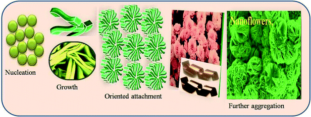
CuO thin films were deposited using the chemical bath deposition (CBD) method. Briefly, aqueous solution of 0.1 M Cu(NO3)2 (copper(II) nitrate) was used as a source of copper with aqueous ammonia as the complexing agent. The resultant solution pH after the addition of ammonia was ∼12. Well-cleaned, flexible copper-foil substrates were immersed in the above bath and the bath was heated. When the bath reached 343 K, precipitation began. During precipitation, the heterogeneous reaction occurred on the foil and deposition of CuO took place on the substrate. Copper substrate coated with CuO thin films was removed after 45 min from the bath, washed with double-distilled water, dried in air and stored in an airtight container. Scheme 1 shows the plausible mechanism for the formation of CuO 3D-nanoflowers on copper foil. The formation mechanism of the 3D-nanoflower-like CuO proceeds by the following stages: nucleation, growth, and oriented attachment. The nucleation is dependent on the amount of supersaturation. In the nucleation stage, supersaturation is very high and electrostatic repulsion barriers are low; hence particles tend to aggregate. Reaction temperatures also increase the nucleation rate and enhance the growth progression. The adjoining nanoparticles grow along a particular crystal orientation due to the oriented attachment and form 3D-nanoflower-like nanostructure.2.1 Characterization techniques
Structural arrangement of copper oxide (CuO) films was carried out with an X-ray diffractometer (XRD) using Cu-Kα radiation (K = 1.54 Å). X-Ray photoelectron spectroscopy (XPS) was carried using electron spectra for chemical analysis (ESCA) VG Multilab 2000 (Thermo VG Scientific, UK). Nitrogen adsorption–desorption was determined by Brunauer–Emmett–Teller (BET) measurements using an ASAP-2010 surface area analyzer. The film surface morphology was observed by scanning electron micrograph (SEM) and transmission electron microscopy (TEM; FEI Tecnai). Supercapacitor formation and respective studies were carried out using the EG&G 263A (Princeton Applied Research Potentiostat), forming an electrochemical cell comprised of CuO films as a working electrode, platinum as a counterelectrode and saturated calomel electrode (SCE) as a reference electrode in KOH electrolyte. Galvanostatic charge–discharge (GCD) studies were carried out using the WBCS3000 Automatic Battery Cycler system. The electrochemical impedance study was performed using the ZIVE SP5 electrochemical workstation.2.2 Electrode preparation and electrochemical measurements
The electrochemical performance was analyzed using a CHI-660-D electrochemical workstation. Electrochemical measurements were carried out using three electrode cell configurations with CuO as the working electrode, platinum as the counterelectrode and Ag/AgCl as the reference electrode with KOH as an electrolyte. The cyclic voltammetry measurements of the CuO electrode were performed at different scan rates in a potential window of 0.0–0.7 V. The charge–discharge characterization was performed at different current densities within a potential window of 0.0–0.7 V. Electrochemical impedance measurements were carried out between 1 Hz and 100 MHz with AC amplitude of 5 mV and bias potential of 0.35 V.3. Results and discussion
Fig. 1a shows the typical XRD patterns of copper foil and nanoflower (NF)-like CuO deposited on copper foil. The peaks observed at (110), (002), (−111), (022), (−223) and (−131) in XRD patterns belong to the monoclinic structure of CuO [JCPD: 080-0076].15 Further, the grain size of CuO, 20 nm, was calculated using the Scherer relation. Fig. 1b and c show the core XPS spectra of Cu2p and O1s, respectively. The results can distinguish CuO from metallic copper or Cu2O both by the appearance of the strong shake-up peak at the high binding energy side of the Cu2p3/2 main peak and the increase in the binding energy of the main peak, implying the presence of an unfilled Cu3d9 shell and thus further confirming the existence of Cu2+ in the sample16 of the CuO. In addition, the O1s spectrum in Fig. 1c shows broad asymmetric peaks with binding energies at 529.49 and 531.31 eV, which correspond to the oxygen in CuO and Cu(OH)2, respectively. | ||
| Fig. 1 (a) X-Ray diffraction patterns of copper foil and Cu foil coated with CuO electrode; (b) core-level XPS spectrum of Cu2p; (c) core-level XPS of O1s for CuO samples. | ||
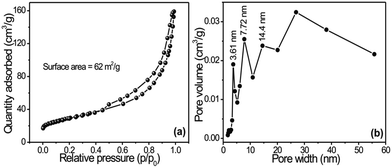
Fig. 2a shows the N2 adsorption–desorption isotherms of copper oxide (CuO) nanoflowers on flexible copper foil synthesized at 343 K, and Fig. 2b shows the corresponding Barrett–Joyner–Halenda (BJH) pore-size distribution plots. The isotherm curves of CuO 3D nanoflowers confirmed type IV isotherms with H3 hysteresis loops that mostly corresponded to the presence of aggregated petals like particles with slit-shape pores, according to the Brunauer–Deming–Deming–Teller (BDDT) classification. The pore-size distributions of nanopetals specified a mesoporous nature with sizes ranging from 3 to 14 nm (Fig. 2b). These results show the same pore radius (14 nm) with different pore volumes and mesopores. The BET specific surface area of the product was found to be 62.7 m2 g1, which is nearly twice as large as that reported by Fu et al.17 This result strongly supports the outcomes of SEM and XRD studies. The vertically grown nanoplate structure exhibited the highest surface area with the smallest pore radius of 3 nm. Such types of surface morphology with well-developed smaller pores provide more active sites for chemical reactions and are advantageous for energy storage applications.18
 | ||
| Fig. 2 (a) Nitrogen adsorption–desorption isotherm of CuO nanostructures synthesized on copper foil; (b) shows corresponding BJH pore-size distribution plots. | ||
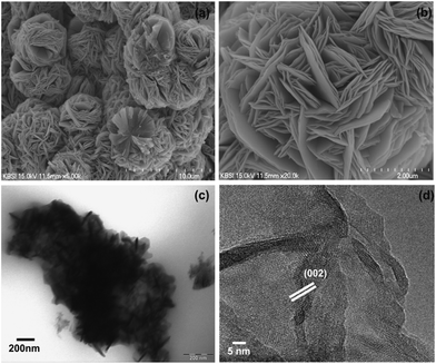
Fig. 3a and b show SEM images of CuO thin film on copper foil at two different magnifications. The low-magnified image shows (Fig. 3a) that the substrate surface was covered with homogeneous and uniform nanoflowers. Self-assembled, three-dimensional (3D) and unique nanostructures have been observed. The average diameter of the flower-like structure was in the range of 2–4 μm. Further, it was revealed that the nanoflowers were composed of several dozen porous nanopetals connected with each other, forming a 3D-nanoflower-like architecture (Fig. 3b). These nanopetals are interconnected with each other, which provides a high volumetric-specific surface area and good mass transport property,19 and generates pores and crevices that allow a large surface area for easy diffusion of the electrolyte onto the nanopetal surface.20
Fig. 3c and d show, respectively, the TEM and HRTEM images of a representative nanoflower-like CuO nanostructure; these are in good agreement with the results from the SEM images. Note that the CuO nanostructure exhibits smooth ultrathin nanopetals of ∼10 nm thickness with 3D flower shapes. High-resolution TEM (Fig. 3d) revealed that the nanoplates had reasonable crystallinity, with lattice spacing of 0.2 nm, which corresponds to the interplanar spacings of 3D nanoflowers CuO (002). This result was also revealed by the XRD patterns. Such ultrathin nanopetals with 3D-nanoflower-like architecture provided easy access for electrolyte ions, which is very useful for supercapacitors.
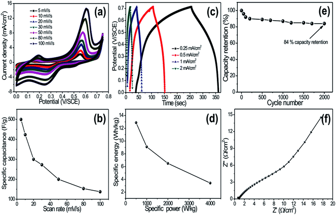
Fig. 4a shows the cyclic voltammetry (CV) curves of the CuO electrode at various scan rates in 1 M KOH electrolyte. Each CV curve consists of a pair of strong redox peaks, which indicates that the capacitance characteristics are mainly governed by the redox (Cu2+ to Cu+ and Cu+ to Cu2+) process. It is further noted that the scan rate is increased, the shape of the CV changes, and the potentials of the anodic and cathodic peaks shift towards more positive and negative directions, respectively. The capacitance values are determined by measuring the integrated charge from the CV. Fig. 4b shows the variation of specific capacitance with scan rates. Note that CuO nanoflowers exhibited a maximum specific capacitance of 498 F g−1 at a scan rate of 5 mV s−1. Moreover, a decrease in capacitance with increased scan rate is observed, which is attributed to the presence of inaccessible inner active sites that cannot sustain the redox transitions due to the diffusion effect of ions in the electrode. Several authors have investigated supercapacitive properties of CuO thin films. For example, Patake et al.21 reported the value of specific capacitance 36 F g−1 in KOH electrolyte for copper oxide nanoparticles synthesized by the electrodeposition method, and Dubal et al.7 reported a specific capacitance of 43 F g−1 in Na2SO4 electrolyte for CuO thin film deposited by the CBD method. The reason for high specific capacitance in the present investigation might be unique, as the 3D-nanoflower-like architecture provided a fast ionic transportation path.
Galvanostatic charge–discharge curves of CuO electrodes at different current densities are presented in Fig. 4c. The shape of the discharge curves was not an ideal straight line, suggesting the contribution of a faradaic reaction. Initial voltage drop during discharge was attributed to internal resistance of the CuO material. The unique 3D-nanoflower-like architecture provided an easy path for intercalation and de-intercalation of ions, which effectively reduced the internal resistance of the material. Note that the initial voltage loss was small even at the high current densities, indicating fast I–V response and low internal resistance in the supercapacitors. Energy and power densities were calculated from the discharge curves at different current densities and are plotted in Fig. 4d. Impressively, the CuO-nanoflower-like electrode showed high energy density of 26 W h kg−1 with high power density of 4 kW kg−1. The cycling endurance measurement of over 2000 cycles for the CuO electrode was conducted by using CV cycling at a scan rate of 100 mV s−1. Fig. 4e shows the resulting capacitance retention as a function of cycling number. It can be seen that the CuO electrode exhibited excellent cycling stability, retaining 84% of initial capacitance after 2000 cycles. Long-term cycling stability of the CuO electrode was attributed to the uniform 3D architecture of CuO and good adhesion of the Cu foil that suppressed the dissolution and agglomeration of CuO detachment during cycling tests.
Electrochemical impedance test of CuO electrode was taken at open circuit potential in KOH electrolyte; the Nyquist plot is shown in Fig. 4f. In EIS, spectrum exhibits one partially intercrossed and low semicircles at the high frequency region, which can be attributed to redox reactions, which is very useful for supercapacitor application. Depression of the semicircles was an implication of electrode surface roughness. The EIS results show the pseudocapacitance characteristics and porous structure feature of the CuO electrode.
4. Conclusions
We have successfully grown a unique, 3D-nanoflower-like CuO architecture on Cu foil by the CBD method and applied it in supercapacitors. The physico-chemical characterizations have shown the formation of monoclinic, 3D-nanoflower-like CuO thin films. This unique nanostructured CuO exhibited high specific capacitance of about 498 F g−1 at 5 mV s−1, with high energy density of 32 W h kg−1. These results suggest that such CuO nanoflowers are promising electrode materials for supercapacitors.References
- S. Boukhalfa, K. Evanoff and G. Yushin, Energy Environ. Sci., 2012, 5, 6872 CAS.
- X. F. Sun, Y. L. Xu, J. Wang and S. C. Mao, Int. J. Electrochem. Sci., 2012, 7, 3205 CAS.
- K. H. Chang, C. C. Hu and C. Y. Chou, Chem. Mater., 2007, 19, 2112 CrossRef CAS.
- (a) D. P. Dubal, J. G. Kim, Y. Kim, R. Holze, C. D. Lokhande and W. B. Kim, Energy Technol., 2014, 2, 325 CrossRef; (b) C. C. Hu, K. H. Chang, M. C. Lin and Y. T. Wu, Nano Lett., 2006, 6, 2690 CrossRef CAS PubMed.
- J. Y. Son, Y. H. Shin, H. J. Kim and H. M. Jang, ACS Nano, 2010, 4, 2655 CrossRef CAS PubMed.
- X. Zhang, W. Shi, J. Zhu, D. J. Kharistal, W. Zhao, B. S. Lalia, H. H. Hng and Q. Yan, ACS Nano, 2011, 5, 2013 CrossRef CAS PubMed.
- D. P. Dubal, D. S. Dhawale, R. R. Salunkhe, V. S. Jamdade and C. D. Lokhande, J. Alloys Compd., 2010, 492, 26 CrossRef CAS PubMed.
- C. D. Lokhande, D. P. Dubal and O. S. Joo, Curr. Appl. Phys., 2011, 11, 255 CrossRef PubMed.
- H. Zhang, J. Feng and M. Zhang, Mater. Res. Bull., 2008, 43, 3221 CrossRef CAS PubMed.
- Y. K. Hsu, Y. C. Chen and Y. G. Lin, J. Electroanal. Anal., 2012, 673, 43 CrossRef CAS PubMed.
- (a) H. Siddiqui, M. S. Qureshi and F. Z. Haque, Optik, 2014, 125, 4663 CrossRef CAS PubMed; (b) Y. Wang, T. Jiang, D. Meng, J. Yang, Y. Li, Q. Ma and J. Han, Appl. Surf. Sci., 2014, 317, 414 CrossRef CAS PubMed; (c) T. Yu, X. Zhao, Z. X. Shen, Y. H. Wu and W. H. Su, J. Cryst. Growth, 2004, 268, 590 CrossRef CAS PubMed; (d) B. Liu and H. C. Zeng, J. Am. Chem. Soc., 2004, 126, 8124 CrossRef CAS PubMed.
- (a) C. J. Love, J. D. Smith, Y. H. Cui and K. K. Varanasi, Nanoscale, 2011, 3, 4972 RSC; (b) J. Y. Xiang, J. P. Tu, L. Zhang, Y. Zhou, X. L. Wang and S. J. Shi, J. Power Sources, 2010, 195, 313 CrossRef CAS PubMed; (c) F. Zhang, A. Zhu, Y. Luo, T. Yang, J. Yang and Q. Yao, J. Phys. Chem. C, 2011, 114, 19214 CrossRef; (d) S. Y. Gao, S. X. Yang, J. Shu, S. X. Zhang, Z. D. Li and K. Jiang, J. Phys. Chem. C, 2008, 112, 19324 CrossRef CAS.
- (a) D. P. Dubal, G. S. Gund, R. Holze and C. D. Lokhande, J. Power Sources, 2013, 242, 687 CrossRef CAS PubMed; (b) Y. K. Hsu, Y. C. Chen and Y. G. Lin, J. Electroanal. Chem., 2012, 673, 43 CrossRef CAS PubMed; (c) Y. Li, S. Chang, X. Liu, J. Huang, J. Yin, G. Wang and D. Cao, Electrochim. Acta, 2012, 85, 393 CrossRef CAS PubMed; (d) D. P. Dubal, G. S. Gund, R. Holze, H. S. Jadhav, C. D. Lokhande and C. J. Park, Dalton Trans., 2013, 42, 6459 RSC.
- Stability Constants of Metal Ion Complexes Supplement 1, ed. L. G. Sillen and A. F. Martell, The Chemical Society, London, 1971 Search PubMed.
- Y. Li, S. Chang, X. Liu, J. Huang, J. Yin, G. Wang and D. Cao, Electrochim. Acta, 2012, 85, 393 CrossRef CAS PubMed.
- M. Yin, C. K. Wu, Y. Lou, C. Burda, J. T. Koberstein, Y. Zhu and S. O'Brien, J. Am. Chem. Soc., 2005, 127, 9506 CrossRef CAS PubMed.
- Y. Fu, Q. Chen, M. He, Y. Wan, X. Sun, H. Xia and X. Wang, Ind. Eng. Chem. Res., 2012, 51, 11700 CrossRef CAS.
- S. K. Shinde, D. P. Dubal, G. S. Ghodake, D. Y. Kim and V. J. Fulari, J. Electroanal. Chem., 2014, 732, 80 CrossRef CAS PubMed.
- M. Zhu, D. Meng, C. Wang and G. Diao, ACS Appl. Mater. Interfaces, 2013, 5, 6030 CAS.
- S. K. Shinde, D. P. Dubal, G. S. Ghodake and V. J. Fulari, Mater. Lett., 2014, 126, 17 CrossRef CAS PubMed.
- V. D. Patake, S. S. Joshi, C. D. Lokhande and O. S. Joo, Mater. Chem. Phys., 2009, 114, 6 CrossRef CAS PubMed.
- M. Li, W. Guo, H. Li, S. Xu, C. Qu and B. Yang, Appl. Surf. Sci., 2014, 317, 100 CrossRef PubMed.
- X. Dong, K. Wang, C. Zhao, X. Qian, S. Chen, Z. Li, H. Liu and S. Dou, J. Alloys Compd., 2014, 586, 745 CrossRef CAS PubMed.
- G. Wang, J. Huang, S. Chen, Y. Gao and D. Cao, J. Power Sources, 2011, 196, 5756 CrossRef CAS PubMed.
| This journal is © The Royal Society of Chemistry 2015 |


