
 Open Access Article
 This Open Access Article is licensed under a
 Creative Commons Attribution 3.0 Unported Licence
Carbon materials for ion-intercalation involved rechargeable battery technologies
Gang
Wang
 ,
Minghao
Yu
* and
Xinliang
Feng
*
,
Minghao
Yu
* and
Xinliang
Feng
*
Department of Chemistry and Food Chemistry & Center for Advancing Electronics Dresden (cfaed), Technische Universität Dresden, 01062 Dresden, Germany. E-mail: minghao.yu@tu-dresden.de; xinliang.feng@tu-dresden.de
First published on 21st December 2020
Abstract
The ever-increasing energy demand motivates the pursuit of inexpensive, safe, scalable, and high-performance rechargeable batteries. Carbon materials have been intensively investigated as electrode materials for various batteries on account of their resource abundance, low cost, nontoxicity, and diverse electrochemistry. Taking use of the reversible donor-type cation intercalation/de-intercalation (including Li+, Na+, and K+) at low redox potentials, carbon materials can serve as ideal anodes for ‘Rocking-Chair’ alkali metal-ion batteries. Meanwhile, acceptor-type intercalation of anions into graphitic carbon materials has also been revealed to be a facile, reversible process at high redox potentials. Based on anion-intercalation graphitic carbon materials, a number of dual-ion battery and Al-ion battery technologies are experiencing booming development. In this review, we summarize the significant advances of carbon materials in terms of the porous structure, chemical composition, and interlayer spacing control. Fundamental mechanisms of carbon materials as the cation host and anion host are further revisited by elaborating the electrochemistry, intercalant effect, and intercalation form. Subsequently, the recent progress in the development of novel carbon nanostructures and carbon-derived energy storage devices is presented with particular emphasis on correlating the structures with electrochemical properties as well as assessing the device configuration, electrochemical reaction, and performance metric. Finally, perspectives on the remaining challenges are provided, which will accelerate the development of new carbon material concepts and carbon-derived battery technologies towards commercial implementation.
 Gang Wang | Gang Wang received his PhD degree in Physical Chemistry from the University of Chinese Academy of Sciences and Institute of Coal Chemistry, CAS in 2016. Then as a postdoctoral researcher, he joined Prof. Klaus Müllen's group at Max Planck Institute for Polymer Research and Prof. Xinliang Feng's group at Technische Universität Dresden. Currently, he mainly focuses on electrochemical energy storage research in novel carbon materials, carbon hybrids and carbon-rich frameworks, and constructing high-efficiency energy storage devices (Li/Na-ion batteries, anion batteries) with particular function/property. |
 Minghao Yu | Minghao Yu received his PhD degree in Material Physics and Chemistry from Sun Yat-sen University in June 2017. In November 2017, he joined Prof. Xinliang Feng's group as a postdoctoral research associate at Technische Universität Dresden (TU Dresden) with the support of Humboldt Research Fellowship. In March 2019, he became a research group leader of the Chair for Molecular Functional Materials at TU Dresden. His research interests focus on the development of advanced functional materials for applications of energy storage (supercapacitors and metal-ion batteries) and conversion (electrocatalysis and metal–air batteries). |
 Xinliang Feng | Xinliang Feng has been full professor and the head of the Chair of Molecular Functional Materials at Technische Universität Dresden since 2014. His current scientific interests include organic synthesis, supramolecular chemistry of π-conjugated systems, bottom-up synthesis and top-down fabrication of graphene and graphene nanoribbons, 2D polymers and supramolecular polymers, as well as 2D carbon-rich conjugated polymers for (opto)electronic applications and materials for energy storage and conversion. |
1. Introduction
Under the global scenario of depletion of non-renewable fossil fuels and growing environmental concerns, the electricity market is now undergoing a unique transformation by the rise of power generation from variable renewable sources, such as wind, solar, and tide.1–3 This transformation puts electricity at the forefront of the clean-energy exploitation, helping to cut air pollution and CO2 emission. It also imposes a strong requirement of reliable energy storage technologies to smooth out the intermittency of renewable energy production.4–6 Among various energy storage technologies, rechargeable battery energy storage provides an intelligent way to manage power supply by storing electricity in the form of chemical energy with high efficiency.7–9 Li-ion batteries (LIBs), which represent the fast-growing rechargeable battery technology, store charge by employing Li+ as the charge carrier.10 Li+ moves from the anode to the cathode through the electrolyte when LIBs are charged, while Li+ moves in the opposite direction when LIBs are discharged. In the past few decades, LIBs have attained great success in powering portable electronic devices, electric vehicles, and smart grids.11 Excitingly, the 2019 Nobel Prize in Chemistry was awarded to John B Goodenough, M. Stanley Whittingham and Akira Yoshino, who dramatically contributed to the development of this revolutionary energy technology. Nevertheless, the widespread implementation of LIBs is still of great concern, which is severely hindered by their unsatisfactory durability (less than 1000 cycles), high cost ($900–1300 per kW h), and insufficient safety.12,13 With the hope of solving the intrinsic bottlenecks of LIBs, extensive efforts have been devoted to developing new battery chemistries relying on different charge carrier ions (such as Na+, K+, Mg2+, Zn2+, Al3+ and anions), also known as post-LIBs.9,14 A significant portion of post-LIBs makes use of inherently safe, low-cost, and naturally abundant raw materials. For a broad market penetration, further improvement in electrochemical performance (including energy density, power density, and cycling stability) and cost is essential for advanced battery technologies.Carbon is one of the most abundant elements in nature, which is the basis of the whole organic chemistry.15,16 In this regard, carbon materials can be easily and cheaply produced by straightforward conversion reactions. Taking advantage of the favorable features like superb chemical stability, good conductivity, large specific surface area, and unique porosity, carbon materials have a long history of use as electrodes in a wide spectrum of battery technologies.17 In 1991, Sony Corporation, for the first time, technically realized the prototype LIBs, in which graphite was used as the Li+-intercalation anode. Extensive explorations have been conducted to provide a profound understanding and optimization of graphite intercalation compounds. To date, graphite is still in use as a commercial anode for LIBs. Meanwhile, numerous carbon nanomaterials were discovered in the past three decades, including one-dimensional (1D) carbon nanotubes (CNTs) and two-dimensional (2D) graphene.17 These new types of carbon allotropes possess significant differences not only in morphology and dimensionality, but also in local electronic structures. Thus, the Li+-storage ability of these carbon nanomaterials has also attracted extensive research interest. Recent studies have also uncovered a substantially enhanced Li-storage capacity for disordered carbon materials with partially graphitic domains. These partially graphitic carbon materials are featured by a large fraction of highly disordered graphene domains, as well as a pronounced mixture of sp2–sp3 carbon. To boost the Li+ storage kinetics, more and more efforts have been devoted to constructing porous carbon materials with adjustable pore size and large specific surface area, which enables a facile electrolyte infiltration and a large electrode/electrolyte interface. On the other hand, with the lessons learned from Li+ intercalation of carbon materials, the rapid emergence of post-LIBs has motivated the exploration of carbon materials as host anodes for post-LIBs under cation-intercalation chemistries (e.g. Na+ and K+). However, due to the distinct physical and chemical features of charge carriers and the electrolyte, the Na+ and K+ intercalation behavior of carbon materials has been demonstrated to be substantially different from the Li+ intercalation process. Compared to other high-capacity anode materials working under alloy reaction (Si, P, and Al)18–22 or conversion reaction (MeOx, MeSx, and MeSex)23–26 mechanisms, cation-intercalation carbon materials are inferior in specific capacity. However, the low working potential and minimized structural variation of carbon anodes during cation storage endow batteries with high working voltage and long cycling life.
Apart from cation-intercalation chemistry, the anion-intercalation chemistry of graphite in a concentrated acid electrolyte was first reported by Rüdorff and Hofmann in 1938.27 Shortly after, systematic research has been carried out to explore the various anion-intercalation chemistries (including BF4−, PF6−, ClO4−, AsF6−, SbF6−, AlCl4−, bis(trifluoromethanesulfonyl)imide (TFSI−)) of carbon materials in nonaqueous electrolytes.28,29 The unique anion-intercalation chemistry of carbon materials with high intercalation potential opens up new application opportunities for carbon materials as favorable cathodes for dual-ion batteries (DIBs) and aluminum-ion batteries (AIBs). As the name implies, DIBs rely on both anions and cations in electrolytes to store charge. Anions and cations are incorporated into anodes and cathodes respectively during charging, whereas anions and cations are released from the electrodes into the electrolyte when DIBs are discharged. In 1989, McCullough et al.30 patented the first DIB device with a cation-intercalation carbon anode and an anion-intercalation carbon cathode. To date, a number of DIB systems have been developed, most of which comprise an anion-intercalation carbon cathode together with varying cation-intercalation anodes and different charge-carrier ions. Although different p-type organic molecules/polymers31–35 can also be used to store anions by reversible redox reactions, the high cost and the intrinsic insulating/semiconducting nature of organic materials make it rather challenging for practical application. Moreover, the dissolution of organic compounds in aprotic electrolytes is also a long-standing concern.
Thus, carbon materials have emerged as an important category of material candidates for ion-intercalation energy storage technologies. A blooming research activity has been conducted in the last few years, aiming to rationally fabricate favorable carbon structures, fundamentally understand the origin of their unique ion-intercalation chemistry, as well as employ them to develop new battery technologies (Fig. 1). In fact, many reviews have more or less discussed the important role of carbon materials in different battery systems.28,29,36–43 However, a comprehensive review on the advanced ion-intercalation chemistry of carbon materials and its application in different energy storage technologies is still lacking. Herein, we first revisit the structure and properties of ion-intercalative carbon materials with an emphasis on chemical and structural principles to design advanced ion-intercalative carbon materials. A pedagogical description of the underlying mechanism is then provided systematically with respect to both cation-intercalation chemistry and anion-intercalation chemistry of carbon electrodes. Afterwards, the recent progress in energy storage technologies based on ion-intercalative carbon electrodes is summarized by categorizing them into cation-based ‘rocking chair’ batteries and emerging anion-involved DIBs. Lastly, the remaining challenges and main development directions for ion-intercalation carbon structures and energy storage devices based on them are addressed.
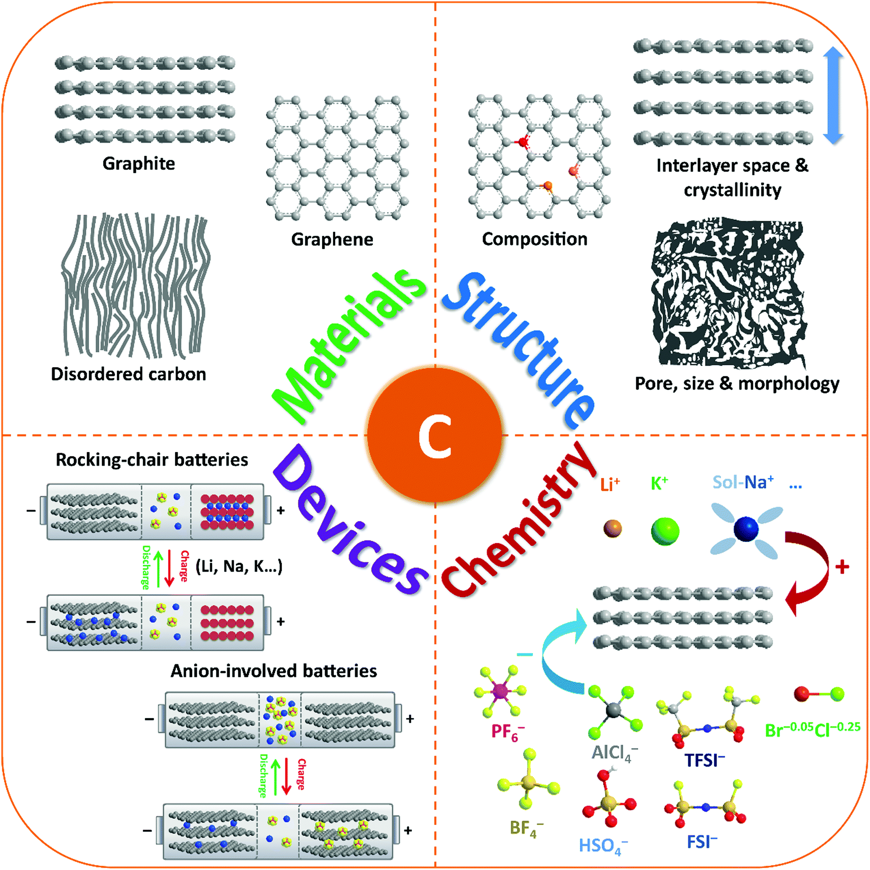 | ||
| Fig. 1 Schematic illustration of the review content including carbon-based materials, structures, ion-intercalation chemistry, and battery devices. | ||
2. Structures and properties of ion-intercalative carbon materials
2.1 Properties of ion-intercalative carbon materials
Ion-intercalative carbon materials generally come in two different forms, namely ordered carbon and disordered carbon. Owing to the different topological structures, different carbon materials exhibit apparently distinct electrochemical behavior for ion intercalation. In this section, we evaluate the structural properties and synthesis routes of different types of carbon materials.Graphite is the ‘oldest’, and still one of the most common anode materials for LIBs, which delivers a high theoretical capacity of 372 mA h g−1. Meanwhile, it has also been revealed to be a favorable host material for K+ and various anions. Graphite has a perfect 3D crystalline and layered structure constituted of sp2-hybridized carbon.44 The sp2-hybridized carbon layer stacks along the c-axis with stacking order of either hexagonal AB stacking or rhombohedral ABC stacking (Fig. 2a). The delocalized π-bonds enable high in-plane electronic conductivity in graphite, which is favorable for rapidly bringing the electronic carriers to contact the intercalated ions. Meanwhile, the strong orbital overlap in the first octet makes the sp2 carbon bonds robust in strength. Graphite is also featured by weak van der Waals bonding in the vertical direction of planes, which renders an interlayer spacing of 3.35 Å. This spacing can accommodate guest intercalated ions. Natural graphite is a native element mineral, which can be exploited in metamorphic and igneous rocks. In addition, artificial graphite can be synthesized by graphitizing non-graphitic precursors (e.g. petroleum, coal) in a non-oxygen environment at high temperature above 2000 °C.45
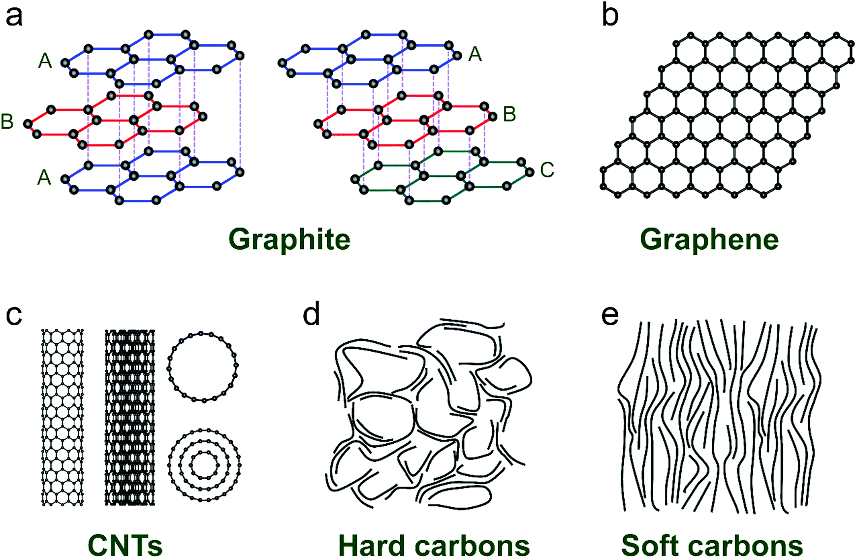 | ||
| Fig. 2 Typical structures of (a) graphite, (b) graphene, (c) carbon nanotubes, (d) hard carbon, and (e) soft carbon. | ||
Graphene and its related carbon materials refer to 2D carbon materials with isolated single or few sp2 carbon layer stacks (Fig. 2b). Graphene can be considered as one- or few-atom thick layer of graphite or an indefinitely extended aromatic molecule. Since the first isolation of graphene from graphite in 2004 by Novoselov et al.,46 graphene has rapidly caught attention from the view of both academic research and industrial application due to its distinguished properties. Graphene displays ultra-strong mechanical properties with a tensile strength of 125 GPa and a Young's modulus of up to 1100 GPa.47 The electrical conductivity and charge mobility of graphene are measured to be 1 × 10⁸ S m−1 and 2 × 105 cm2 V−1 s−1.48 Particularly, the high specific surface area of graphene (up to 2630 m2 g−1) is favorable for energy storage applications.49
The synthesis routes toward graphene can be categorized into bottom-up synthesis and top-down exfoliation from graphite. Generally, the bottom-up synthesis of graphene can be realized by epitaxial growth with structure-defined precursors or chemical vapor deposition (CVD), which allows obtaining graphene with high purity and quality.50–52 However, these methods require expensive precursors and complex processing, significantly hindering the low-cost and massive production of graphene. For example, in CVD methods, catalytic metal substrates (e.g. Ni, Cu) are exposed to hydrocarbon gases (e.g. CH4, C2H4, CO) at a high temperature (>500 °C). Hydrocarbon gases are decomposed, diffused and deposited on metal surfaces, followed by nucleation and growth of graphene. By contrast, the top-down exfoliation strategy can produce graphene in much larger amounts under facile synthetic conditions. The most general top-down approach is modified Hummers’ method, which was first proposed in 1958.53 In such a method, graphite flakes are chemically oxidized into graphite oxide (GO) in a strong oxidation environment. The decorated oxygen-containing functional groups would expand the layer distance of graphite and weaken the bonding strength between layers. With the assistance of sonication, GO can be easily delaminated. The graphene material (generally called reduced graphene oxide (rGO)) is obtained by a further reduction step, in either a thermal, chemical, or electrochemical way.54 While this method provides great potential for large-scale production, the produced graphene materials are generally rich in defects and functional groups. Apart from modified Hummers’ method, several other liquid-phase exfoliation approaches have also been developed, which rely on external driving forces (e.g. ultrasonication,55 shearing,56 and electric field57). Of note is that the ion-storage properties of graphene materials vary largely along with lateral dimensions, layer number and defects. These characteristics can be well controlled by adopting different synthesis approaches.
CNTs are representative 1D carbon structures, which were discovered in 1991.58 They can be viewed as carbon cylinders with a diameter of 1–20 nm, obtained by scrolling single or multilayered graphene.59 CNTs have typical tubular structures with a large length-to-diameter ratio. For example, Zhang et al.60 reported a kind of ultralong CNT with length up to 55 cm by employing a floating CVD method. According to the layer number of the wall (Fig. 2c), CNTs are categorized into single-walled CNTs (SWCNTs) and multi-walled CNTs (MWCNTs). Based on the different wrapping angles, SWCNTs show either metallic or semi-conducting features. Eqn (1) describes the vector (ch) of SWCNTs, where a1 and a2 are unit vectors of the graphene layer, and n and m are integers. In general, SWCNTs show a metallic feature when (n − m) is a multiple of 3; otherwise, SWCNTs are semiconductive.61 Unlikely, MWCNTs are composed of coaxial tubules with a constant spacing of 0.34 nm between each two walls, and they generally behave like non-gap metals. Both metallic SWCNTs and MWCNTs present a large specific surface area (up to 1300 m2 g−1), ultrahigh conductivity (up to 5000 S cm−1) and charge carrier mobility (more than 100![[thin space (1/6-em)]](https://www.rsc.org/images/entities/char_2009.gif) 000 cm2 V−1 s−1),62–64 which make them attractive candidates for battery applications.
000 cm2 V−1 s−1),62–64 which make them attractive candidates for battery applications.
| ch = na1 + ma2 | (1) |
Iijima, for the first time, discovered MWCNTs during the synthesis of fullerene by arc discharge deposition.58 Later on, Smalley et al.,65 in 1995, developed a new laser ablation method to produce SWCNTs by treating the graphitic carbon with laser ablation. Afterwards, the CVD method was employed to synthesize CNTs by using gaseous carbon sources with metal catalysts at high temperatures of 500–1200 °C, which soon attracted intense attraction from the community.66–68 Systematic research has been conducted to control the length, diameter, and wall number of CNTs by adjusting the carbon precursors, catalysts, and other CVD parameters. The synthetic details have been well documented in previous review papers.15,69,70
Disordered carbon materials are generally prepared by thermal decomposition of different organic precursors in an inert atmosphere (N2, Ar, and even vacuum) at a high temperature (less than 1500 °C). Depending on the nature of precursors and synthetic conditions, the microstructure and properties of disordered carbon materials have significant difference. Hard carbon materials are generally the pyrolysis product of biomass with insufficient aromatic structures (e.g. sugar, charcoal, cellulose, coconut shells, phenol-formaldehyde resins, and polyvinylidene chloride), whilst soft carbon materials are obtained from pyrolytic aromatic compounds (e.g. pitch, benzene, petroleum coke, polyvinyl acetate, and polyvinyl chloride). During the pyrolysis, the main mass loss of the organic precursor is typically observed in the temperature range of 250–500 °C, which is assigned to the successive release of H and heteroatoms (like O, N, S, etc.) as volatile products (hydrocarbons, H2O, NO2, CO, CO2, SO2, etc.). When the temperature exceeds 700 °C, the precursor is generally considered as carbonized; however, still a small amount of hydrogen and heteroatoms remain, which would be completely removed when the temperature reaches more than 1000 °C. In addition, the synthetic parameters, like heating rate, final temperature, pyrolysis time, and protective gas,73–76 also play an important role in determining the structure and properties of the derived carbon materials.
2.2 Nanoporous structure construction
Recently, nanoporous carbon materials have attracted significant interest from the energy storage community, as they can provide efficient channels for ion transport, considerable available ion-storage sites, as well as remarkable buffers for alleviating the volume change during ion intercalation/deintercalation (Fig. 3a).77,78 According to the definition of International Union of Pure and Applied Chemistry (IUPAC),79 pores are categorized into micropores (<2 nm), mesopores (2–50 nm) and macropores (>50 nm). It is well established that mesopores and macropores can serve as the channels for mass transport; meanwhile micropores play a key role in determining the specific surface area, as well as in permitting a high access of charge-carrier ions to the carbon surface. In the last few years, tremendous research has been conducted on the methodology exploration to precisely control the pore size, shape, and dispersibility in carbon materials. | ||
| Fig. 3 Common strategies to modify carbon materials, including (a) pore construction, (b) interlayer spacing engineering, and (c) chemical modification. | ||
Generally, nanopores can be introduced into carbon materials through two approaches: template-assisted synthesis and post activation. In the case of template-assisted synthesis, templates are classified as hard templates and soft templates. The hard-template method includes the steps of filling the interspace of the hard template with carbon sources, carbonization, and template removal.80,81 This method provides a ready way to tailor the porosity of carbon materials, in which the pore size and pore shape can roughly inherit the nanostructure of the utilized templates. A large number of hard templates have been investigated, including silica, anodic aluminum oxide, other inorganic oxides, soluble salts, polystyrene, molecular sieves, and bio-ceramics. Based on the different properties of hard templates, they can be removed by either physical processing (e.g. sublimation, dissolution) or chemical processing (e.g. corrosion). In contrast, soft templates refer to templates like vesicles, micelles, gas bubbles, and emulsion droplets, which originate from the additives like self-assembled polymers and surfactants.82 Soft templates are easily removed during the carbonization of carbon sources, which avoids the additional template removal process. In comparison with the hard-template method, the soft-template method offers a more convenient and cost-effective way to produce porous carbon materials on a large scale. To construct hierarchical pores, researchers also synthesized nanoporous carbon materials, by combining multiple templates or both hard template and soft template.83
In addition, nanopores can be also introduced into carbon materials by a chemical activation process. Activating agents (such as NaOH, KOH, H3PO4) can penetrate into the inner structure of carbon.84,85 During the carbonization, activating reagents would react with the surrounding carbon atoms, forming continuous and uniform pores. These strong corrosive agents allow a wide coverage of carbon precursors and a high yield of pores, but also suffer from high cost, safety and environmental issues. Apart from strong basic or acid activating agents, some facile agents have also been employed such as gaseous H2O and CO2.86 Partial carbon in the outer shell of carbon materials would be gasified, forming pores. It should be noted that although these activating agents allow large-scale and eco-friendly activation of carbon materials, the efficiency to produce pores is relatively low compared with the method using strong acid/basic agents.
2.3 Interlayer spacing engineering
Interlayer spacing of carbon materials is an important parameter that affects the ion-intercalation behavior and thus the electrochemical performance of carbon electrodes (Fig. 3b). To decrease the interlayer spacing of carbon materials, high temperature treatment is the most frequently adopted strategy. During the graphitization heat treatment at 2000–3000 °C, carbon atoms rearrange to relieve the internal stresses along with the formation of a three-dimensional graphite structure or relatively ordered microcrystallites.87,88 The interlayer spacing of carbon materials gradually decreases together with the removal of defects/functional groups. Normally, the graphitization process takes even several days to obtain heteroatom-free carbon materials. In the presence of catalysts (Fe, Cr, Co, Ni, etc.), the graphitization temperature can be largely decreased (500–1800 °C) and the treatment duration can also be shortened, although the metallic catalysts are likely encapsulated by the graphitic carbon.89–91 The interlayer spacing of carbon aerogel after catalytic graphitization can reach 0.336 nm, very close to 0.335 nm of pure graphite.In addition, increasing the interlayer spacing of layered materials is attractive to facilitate ion diffusion and intercalation under electrochemical conditions. Due to the inert feature of graphite, a two-step oxidation–reduction process was applied,92,93 where graphite was first oxidized to graphite oxide and further reduced at 150–600 °C. Owing to the strong covalent bond between oxygen and graphite, there are oxygen functional group residuals on graphite even after reduction, leading to the large interlayer spacing of graphite (0.34 nm or 0.37–0.43 nm) while maintaining the long-range-ordered layered structure. Another way to enhance the layer distance of graphite is pre-intercalation.94–96 Atomic or molecular layers of chemical species can intercalate into graphite sheets. A stage-I FeCl3–graphite intercalation compound (GIC) has been synthesized by reacting FeCl3 with graphite. The interlayer spacing of graphite was increased to 0.938–0.960 nm. Further, the combination of chloroaluminate anion intercalation, thermal expansion and electrochemical hydrogen evolution on graphite foil led to the formation of three-dimensional graphene foam consisting of thin-layer graphene sheets and well-defined vertical channels.97 Such approaches avoid the introduction of large amounts of functional groups or oxidation-induced defects into graphene sheets.
2.4 Chemical modification of carbon materials
The chemical composition and surface properties of carbon materials have a significant impact on their electrochemical behavior including solid electrolyte interphase (SEI) formation, electrochemical stability and ion intercalation process. There are several ways to modify the composition of carbon materials such as heteroatom doping (Fig. 3c), surface functionalization and heterogeneous species intercalation.Introducing F into graphite leads to fluorinated graphite, which has been commercialized in primary LIBs. Deeply oxidizing graphite produces GO,53 the main source of rGO. Unlike C–F and C–O(![[double bond, length as m-dash]](https://www.rsc.org/images/entities/char_e001.gif) O) dangling bonds98 in fluorinated graphite and GO, boron (B) can be incorporated into the graphite lattice, which brings about enhanced graphitization and modified electronic properties.99 B-Doped graphite can be prepared via mixing a pitch coke and boron oxide powders followed by baking at 1000 °C and graphitization at 2800 °C. The fabricated product with 3.8 wt% B doping exhibited an interlayer spacing of 0.335 nm and a large crystallite size over 100 nm.100 The high graphitization of B-doped graphite was attributed to the catalytic effect of B substitution.
O) dangling bonds98 in fluorinated graphite and GO, boron (B) can be incorporated into the graphite lattice, which brings about enhanced graphitization and modified electronic properties.99 B-Doped graphite can be prepared via mixing a pitch coke and boron oxide powders followed by baking at 1000 °C and graphitization at 2800 °C. The fabricated product with 3.8 wt% B doping exhibited an interlayer spacing of 0.335 nm and a large crystallite size over 100 nm.100 The high graphitization of B-doped graphite was attributed to the catalytic effect of B substitution.
Fluorination and oxidation can also be controlled just on the outer surface of graphite under mild reaction conditions.101 To passivate the reactive surface of graphite, particularly the edge planes, mild oxidation of graphite by air generates carbonyl, carboxyl and hydroxyl groups. After lithiation, this dense layer of oxides becomes part of the SEI and inhibits electrolyte decomposition.102,103 In addition, hydrogenation of partially oxidized graphite can be used to fabricate hydrogenated graphite.104 To enhance the electrochemical stability of graphite, surface coating is effective to suppress the potential exfoliation of graphite. Polydimethylsiloxane,105 nitrophenyl layer,106 AlF3,107 and oxide108,109 coatings have been investigated for raw graphite, which endow graphite electrodes with high electrochemical stability and low irreversible capacity. Benefiting from high conductivity, stable intercalation-deposition or intercalation-alloying reactions and high compatibility with nowadays LIB infrastructure, these graphite-based hybrids offer a practical insight into developing high-energy electrodes.
In contrast to chemically inert graphite, graphene with atomic-level thickness can be well modulated with respect to chemical composition. Graphene can reversibly react with atomic hydrogen, which transforms the highly conductive zero-overlap semimetal into an insulator.110 The formed graphane shows crystallinity and retains the hexagonal lattice. In-plane B substitutional doping into graphene was accomplished via chemical vapor deposition.111 Other heteroatom-doped (N, P, O, S, F, Cl, Br, and I) graphene can be fabricated by both in situ synthesis methods and post treatment (chemical vapor deposition, ball milling, bottom-up synthesis, thermal annealing, wet chemical method, plasma, photochemical method, and arc discharge).112 Similarly, heteroatoms can be doped in soft-carbon and hard carbon during the thermal synthesis.113–116 The heteroatoms in the graphitic planes can act as reactive adsorption sites for alkaline cations and expand the interlayer spacing, thus enhancing the capacity.
Moreover, the electrode design also influences the ion transport across the electrode and the ion intercalation kinetics, especially for practical thick electrodes with high mass loadings.117,118 Claire Villevieille et al.119 demonstrated thick graphite electrodes with a vertically aligned architecture, which was enabled by superparamagnetic Fe3O4 nanoparticles adsorbed on graphite flakes. The platelet orientation can be magnetically controlled in a simple, inexpensive, and effective way. The vertically aligned graphite flakes decrease the tortuosity of the ion path throughout the electrode by a factor of four. Thus, the capacity of graphite at high rates was largely enhanced by providing a shorter pathway for Li+ diffusion. Such a strategy can be potentially extended to other electrode materials for high-rate devices.
3. Electrochemistry and fundamentals
Ion intercalation/deintercalation is the most classic charge storage mechanism in rechargeable battery technologies. The process involves a simple and reversible solid-state redox reaction of the host materials. In the charge storage/release process, mobile guest ions in the electrolyte are reversibly inserted/extracted into/from the interlayer space or large channels of the host materials. The ions keep their ionic properties during intercalation, so that their diffusion within host materials is forced by the electrostatic interaction between ions and host materials. Meanwhile, the intercalation process would lead the host materials to undergo certain volume expansion. As an ideal model, graphite intercalation compounds (GICs) provide the basic understanding of the charge-storage mechanism of carbon for battery technologies. The studies on ionic GICs can be traced back to as early as 1841.120 Graphite with a large π-electronic network can delocalize and stabilize with either an excess of electrons in the antibonding π*-band or electron holes in its bonding π-band, enabling graphite with redox amphotericity and leading to donor-type or acceptor-type GICs. The great success of GICs in batteries further spurred research to understand the battery electrochemistry of other carbon nanostructures (graphene, CNTs, disordered carbon). Therefore, this part mainly concentrates on the fundamental electrochemistry associated with the ion-intercalation behavior of carbon materials.3.1 Cation intercalation
Group IA alkali elements (Li, Na, K) are attractive as intercalants into graphite, because they can easily lose the outermost electrons and form ionic bonds with non-metallic carbon. The formation of donor-type GICs can be expressed as reaction (2), where alkali elements donate an electron to the delocalized π-electron carbon networks. However, the intercalation behavior of Li+, Na+, and K+ into the carbon interlayer shows quite a different electrochemical behavior, which relies on the different chemical and physical properties of Li, Na, K and their cations (Table 1). Along with the increase of the atomic number (from Li to K), alkali elements show increasing relative atomic mass and Shannon's ionic radii, as well as decreasing Pauling electronegativity. In early studies, potassium ion batteries (KIBs) did not attract much attention, because K+ possesses larger relative atomic mass and ionic radii than Li+ and Na+. Nevertheless, it was gradually revealed that the smaller ionic radii of alkali elements resulted in stronger coulombic interaction with the solid host, which causes a larger energy barrier for the mobility of ions within host materials. Moreover, Stokes’ radii and the desolvation energy in propylene carbonate (PC) follow the order Li+ > Na+ > K+,121 implying the possibility of Na+ and K+ as suitable charge carriers for batteries. In addition, since the natural abundance of Na and K greatly exceeds that of Li (2.3 mass% for Na in the earth's crust vs. 1.5 mass% for K and 0.0017 mass% for Li), much lower material cost is expected for the future sodium-ion battery (NIB) and KIB technologies than LIB technology. All these factors together stimulate the intense efforts simultaneously devoted to the research on LIBs, NIBs and KIBs.| Cn + M+ + e− ⇌ Cn−M+ | (2) |
| Element | Li | Na | K |
|---|---|---|---|
| Atomic number | 3 | 11 | 19 |
| Electronic configuration | [He]2s1 | [Ne]3s1 | [Ar]4s1 |
| Relative atomic mass | 6.94 | 23.00 | 39.10 |
| Pauling electronegativity | 0.98 | 0.93 | 0.82 |
| Shannon's ionic radii/Å | 0.76 | 1.02 | 1.38 |
| Stokes’ ionic radii in PC/Å | 4.8 | 4.6 | 3.6 |
| Desolvation energy in PC/kJ mol−1 | 215.8 | 158.2 | 119.2 |
| E° (V) vs. SHE | −3.04 | −2.71 | −2.93 |
| E° (V) vs. Li+/Li | 0 | 0.33 | 0.11 |
| Crust abundance/mass % | 0.0017 | 2.3 | 1.5 |
| Crust abundance/molar % | 0.005 | 2.1 | 0.78 |
| Cost of industrial grade metal/$ ton−1 | 100k | 3k | 13k |
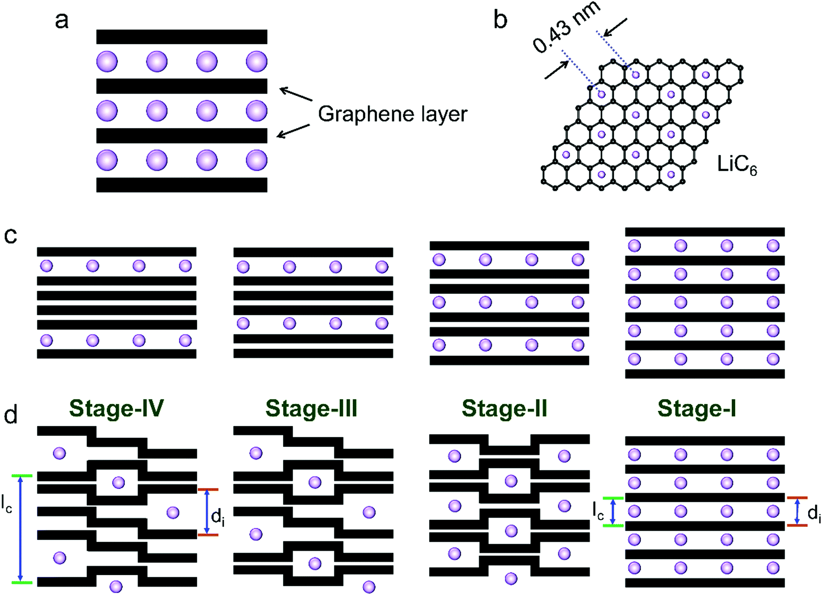 | ||
| Fig. 4 Schematic illustration of (a) Li-intercalated graphite and (b) the formed LiC6 structure. Two models of the stage formation process during Li+ intercalation into graphite: (c) Rüdorff model and (d) Daumas–Hérold model. | ||
The phase transformation of graphite during Li+-intercalation proceeds via a known ‘staging’ mechanism for GICs,126 as shown in Fig. 4c. Li+ tends to fully intercalate into distant graphene layers before occupying the near/neighboring graphene layer, expressing a signature stage structure. The order of the stage is defined by the number of graphene layers between two adjacent Li layers. Different potential steps in the discharge/charge profile and sharp redox peaks disclose the sequential formation of stage-III, stage-II, and stage-I during Li intercalation. Previous studies established two models to simulate the graphite strain, namely Rüdorff model and Daumas–Hérold model (Fig. 4d).127,128 Compared with the sequential filling of ions in alternating graphene interlayer spaces (Rüdorff model, Fig. 4c), the Daumas–Hérold model provides a more reasonable interpretation of strain formation, as graphene layers deform around the intercalated ions. To index the stage number (n) of GICs, two characteristic (00n + 1) and (00n + 2) plane peaks appearing in the XRD patterns of GICs will be analyzed (Fig. 4b and c). Based on eqn (3) and (4), n can be calculated from eqn (5).129,130 The n + 1 and d00n+1 represent the index of (00n + 1) planes oriented in the stacking direction and the observed value of the spacing between adjacent planes, respectively. The key structural parameters of GICs like the periodically repeating distance (Ic), the intercalant gallery height (di), the gallery expansion (Δd) and the percent expansion (Δc) can be achieved by eqn (6) and (7). With the assistance of XRD and Raman spectroscopy, four stages were observed for the Li+ intercalation process into graphite. Both XRD123 and high-resolution transmission electron microscopy (TEM) image131 revealed the interplanar distance to change from 3.35 Å for pristine graphite to 3.70 Å for stage-I (LiC6), implying a Δc of 110% (Table 2).
| d00n+1 = Ic/(n + 1) = λ/(2sinθ00n+1) | (3) |
| d00n+2 = Ic/(n + 2) = λ/(2sinθ00n+2) | (4) |
| n = [1/(sinθ00n+2/sinθ00n+1 − 1)] − 1 | (5) |
| Ic = di + (n − 1) × 3.35 = Δd + n × 3.35 = (n + 1) × d00n+1 | (6) |
| Δc = [Ic/(n × 3.35) − 1] × 100% | (7) |
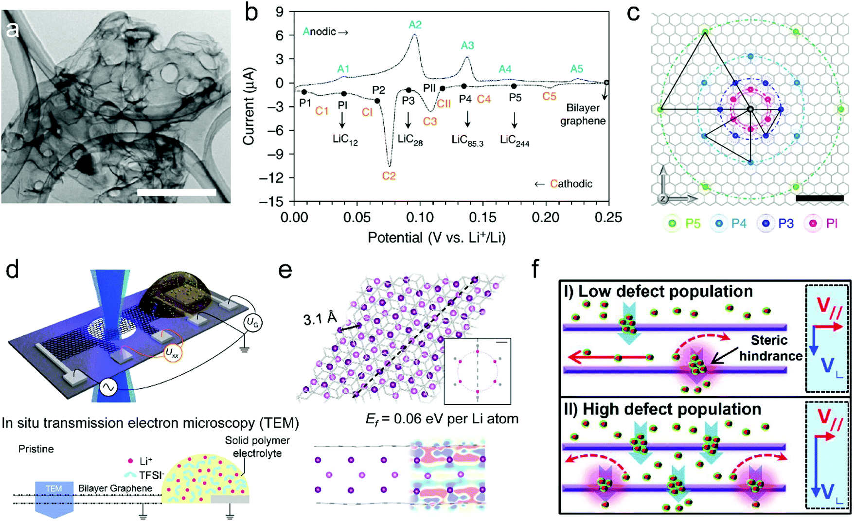 | ||
| Fig. 5 (a) Transmission electron microscopy (TEM) image of the free-standing bi-layer graphene film (scale bar, 1 μm). (b) CV curve of the bi-layer-graphene film and the corresponding LiCx phase. (c) The proposed in-plane distribution of Li in the lithiated bi-layer graphene. Reproduced from ref. 50 with permission from Springer Nature. (d) Schematic of the device for in situ TEM measurements. (e) Fully optimized tri-layer Li between AB-stacked graphene sheets obtained from DFT calculations. Reproduced from ref. 132 with permission from Springer Nature. (f) Schematics of the proposed Li diffusion mechanism through defects on the basal plane with different defect population. Reproduced from ref. 51 with permission from American Chemical Society. | ||
Li-ion storage in CNTs has also been explored in the past few years. It is believed that Li-ion intercalation can occur on the outside of the walls, in the inner core, as well as in the space between multilayers through the topological defects on the side walls or the open ends.136–140 Generally, the gravimetric capacity of CNTs heavily relies on their structures and morphology (ranging from 300 to 1500 mA h g−1). The capacity difference among different CNTs can be assigned to many structural factors, such as chirality, diameter, length, defects, and functional heteroatoms/groups.
Another important category of carbon materials for Li-ion storage is disordered carbon with a large proportion of sp2 carbon. The Li-ion storage behavior of disordered carbon is featured by multiple mechanisms, including intercalation, adsorption, cavity/pore filling, surface/interface storage, and heteroatom/functional group contribution.122,135,141–143 With contributions from different mechanisms, the gravimetric capacity of disordered carbon substantially exceeds that of graphite (LiC6). Although disordered carbon materials show advantageous capacity, their application is severely restricted by two issues, massive irreversibility of the first lithiation process (or low first-cycle coulombic efficiency (CE)) and apparent hysteresis between charge and discharge curves. The irreversible capacity is mainly assigned to the formation of a surface passivation layer on carbon materials due to electrolyte reduction, which is also named SEI.144 In fact, the SEI serves as a prerequisite of cell stability for electrolyte/electrode contact with unstable thermodynamics. Such a passivation layer was found in most of the LIB anodes. For graphite, the irreversible capacity only accounts for 10–20% of the first lithiation capacity.122 It was revealed that SEI formation is heavily dependent on the specific surface area.133 Thus, disordered carbon shows much higher irreversible initial capacity, as it generally possesses larger specific surface area than the highly compacted graphite.
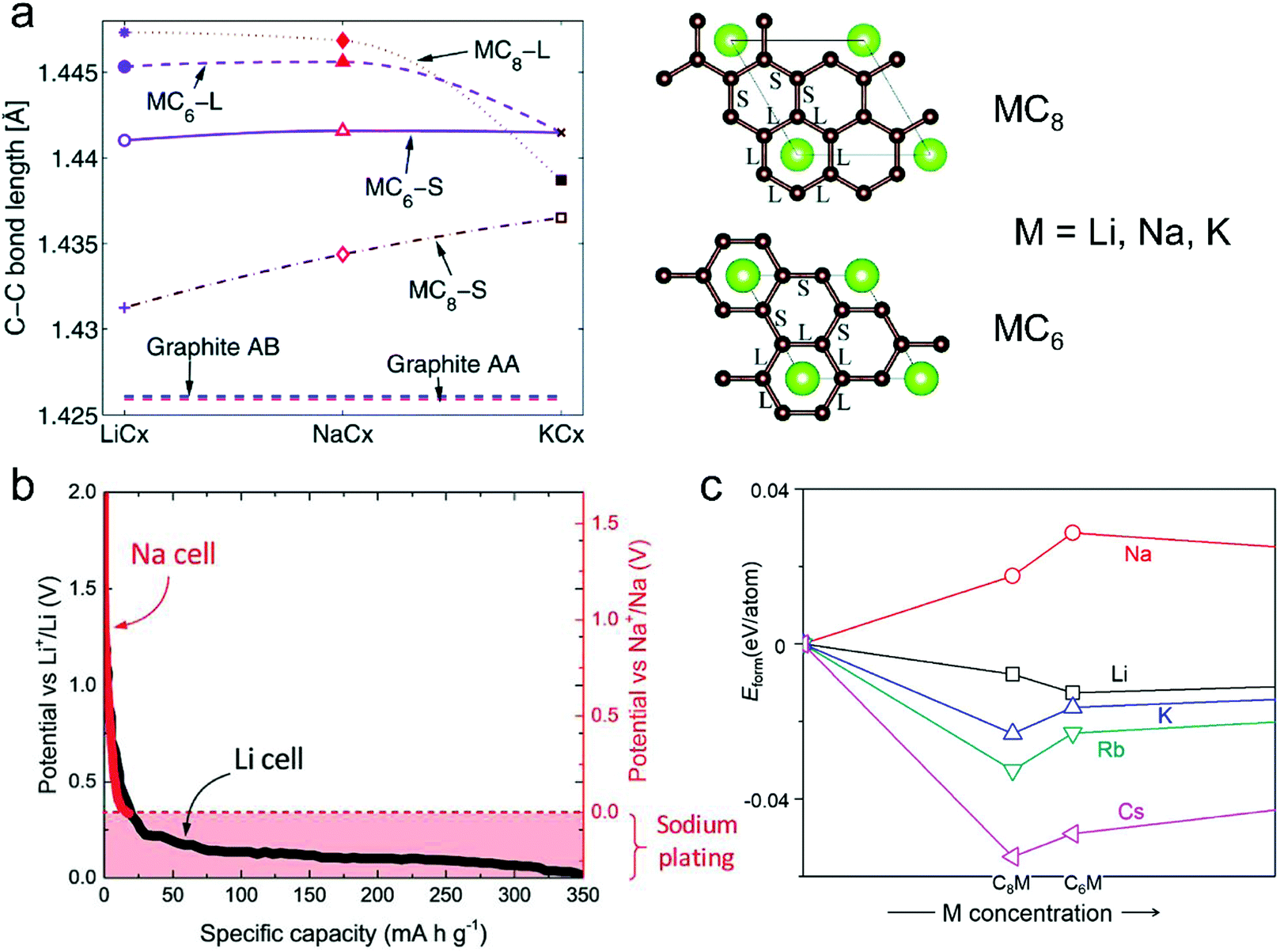 | ||
| Fig. 6 (a) In-plane C–C long (L) and short (S) bonds in MCx intercalation compounds and graphite AB and artificial graphite AA. Configurations of long (L) and short (S) bonds for MC6 and MC8 are illustrated in the right figures. Reproduced from ref. 145 with permission from The Royal Society of Chemistry. (b) Second discharge curve of graphite in Li (black line) and Na cells (red line) with LiPF6 in EC/DEC and NaPF6 in EC/DEC, respectively. Reproduced from ref. 40 with permission from Wiley-VCH. (c) Calculated formation energies of alkali metal (M)–graphite compounds. Reproduced from ref. 146 with permission from United States National Academy of Sciences. | ||
There are two strategies to promote the intercalation of Na+ into graphite. The first one is to increase the graphite layer distance.93,149 It was simulated in theory, when the graphite layer distance increases from the initial 0.335 to 0.37 nm, the Na+ intercalation into graphite occurs with a low energy barrier.150 Chou and co-authors151 found that rGO with an interlayer distance of 0.37 nm could deliver a high capacity of 174.3 mA h g−1 as the anode of NIBs. Wen et al.93 reported that the partially reduced GO with an interlayer distance of 0.43 nm exhibited a high Na+-storage capacity of 284 mA h g−1 at 20 mA g−1. This remarkable capacity was assigned to the increased intercalation space for accommodating Na+. The other strategy is to enable the co-intercalation of Na+ and solvent in diglyme or ether-based electrolytes.124,152–155 Recently, Kang et al.156 revealed that the co-intercalation of Na+ and solvent could avoid the direct interaction between Na+ and graphite layer, greatly reducing the corresponding repulsive interaction. To enable such co-intercalation, a high solvation energy of Na+ is required for solvents, which is capable of forming stable Na–solvent complexes. However, the Na+-storage performance of graphite enabled by the co-intercalation strategy suffers from some critical issues, such as low specific capacity (100 mA h g−1 in a diglyme-based electrolyte, 150 mA h g−1 in an ether-based electrolyte), large volume expansion (350%, as shown in Table 2), and high consumption of solvent.
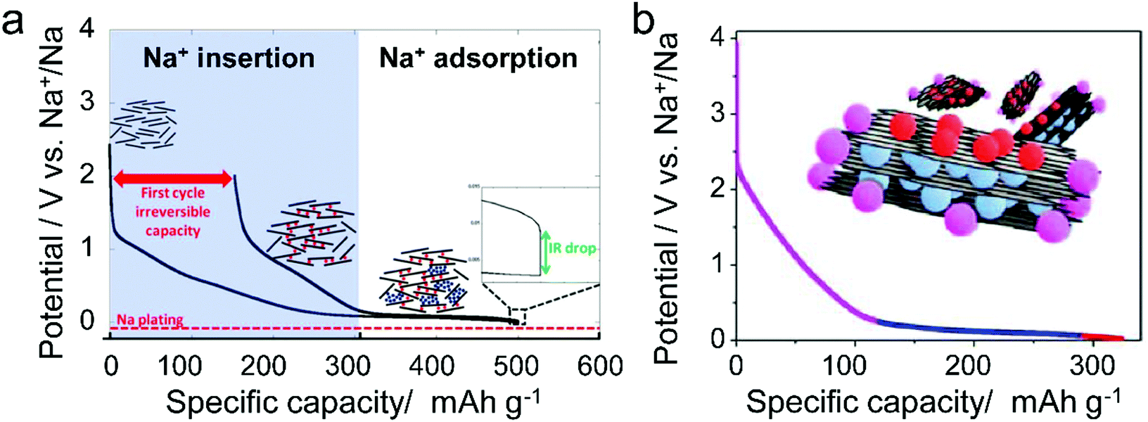
Different from pristine graphite, disordered carbon materials, especially hard carbon, have been recognized as favorable SIB anode materials. The charge–discharge curve of disordered carbon during Na+ intercalation/de-intercalation behaves like Fig. 7, showing a sloping region with potential above 0.1 V and a low potential plateau.71 In brief, four kinds of Na+-storage forms were proposed in the previous literature,40 including (1) capacitive Na-ion adsorption on the accessible surface, (2) pseudocapacitive Na-ion storage associated with the carbon defects, heteroatoms, and functional groups, (3) Na+-intercalation into the graphitic layers and (4) Na clustering within the micropores. However, it remains challenging to establish a clear relationship between the voltage curve of hard carbon and specific Na+-storage mechanisms. For example, Stevens and Dahn157 proposed the ‘house-of-cards’ model, which assigned the high voltage sloping region to Na+ insertion into the turbostratic graphite microdomains and the low voltage plateau region to Na+ adsorption within the microporosity (Fig. 7a). However, other recent studies148 demonstrated that the Na+-storage mechanism in the high voltage sloping region is associated with Na+ adsorption on the defective sites of carbon and filling of micro-/nano-pores, while the mechanism in the plateau region is the insertion of Na+ into the carbon lattice and adsorption of Na+ at the pore surface (Fig. 7b). The ongoing debate on the Na-ion storage mechanism of hard carbon calls for further in situ electrochemical studies on hard carbon materials for Na+ storage with the assistance of multiple characterization techniques. In addition, heteroatom doping can also promote the Na+-storage capability of disordered carbon, as it can provide additional Na+-adsorption sites, and improve the surface wettability and electronic conductivity.158,159 Of note is that the issues for Li+-storage in disordered carbon also exist in the case of Na+ storage, which is the low CE during the first cycle associated with the formation of SEI film.
 | ||
| Fig. 7 Typical voltage profile of hard carbon for Na-storage with two kinds of proposed mechanism. (a) Two-phase mechanism including intercalation and pore filling. Reproduced from ref. 71 with permission from The Electrochemical Society. (b) Three-step Na-storage mechanism. Reproduced from ref. 148 with permission from American Chemical Society. | ||
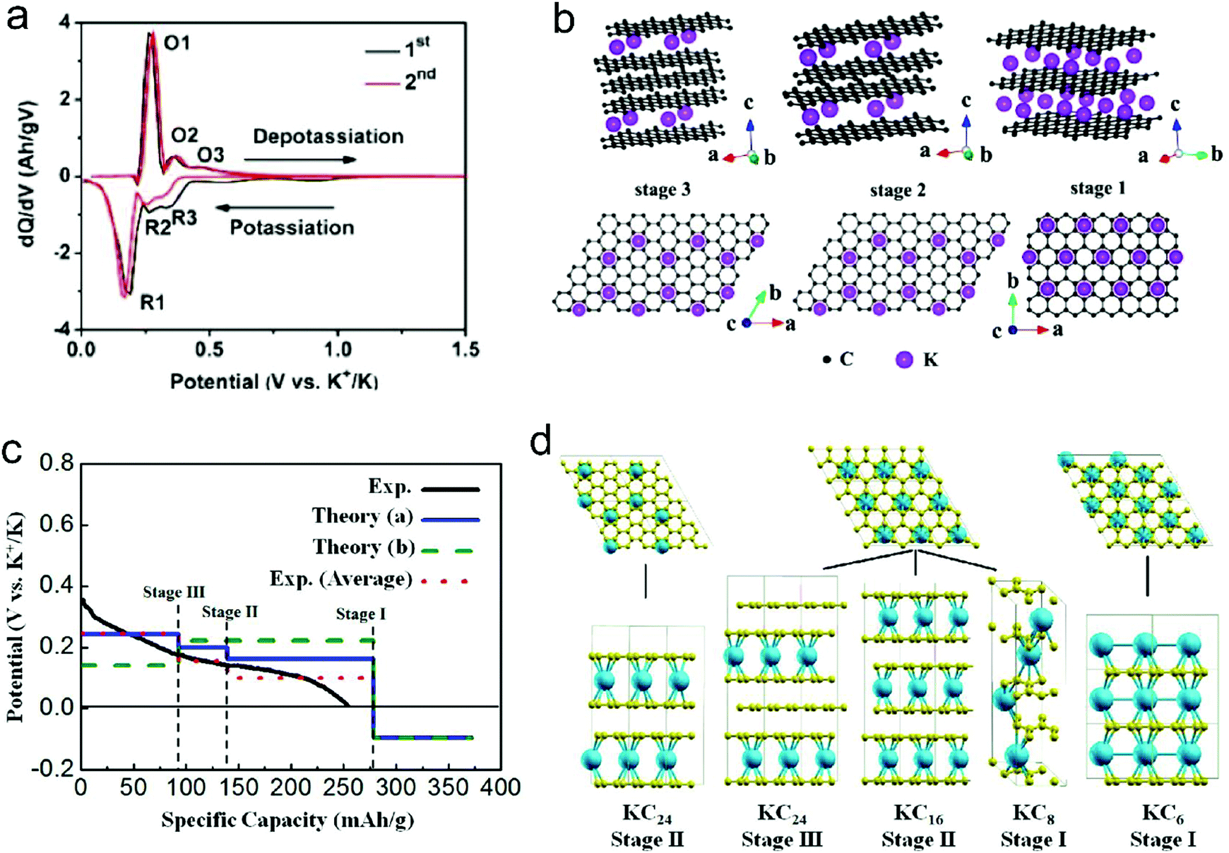 | ||
| Fig. 8 (a) dQ/dV profiles of K+-intercalated graphite. (b) Structure diagrams of K+-intercalated graphite at different stages, side view (top row) and top view (bottom row). Reproduced from ref. 125 with permission from American Chemical Society. (c) Calculated potential profile for K ion intercalation into graphite for different staging scenarios. The blue line (Theory (a)) corresponds to an intercalation staging: KC24 (stage-III) → KC16 (stage-II) → KC8 (stage-I). The green dotted line (Theory (b)) corresponds to calculated values for the previously reported staging: KC24 (stage-II) → KC8 (stage-I). The red dotted line corresponds to the averaged experimental data shifted by 26 mA h g−1 to correct the capacity contribution from SEI formation. (d) Scheme of the different stages of K-intercalated graphite; K shown in blue and C in yellow. Reproduced from ref. 160 with permission from American Chemical Society. | ||
Besides the graphite material, graphene and disordered carbon also show pronounced K+-storage capability. Compared with the voltage profile of graphite with an obvious voltage platform, graphene and disordered carbon generally exhibit more sloping voltage curves, which is particularly obvious in the high voltage region. The corresponding K+-storage mechanisms are close to the mechanisms of similar materials for Li+ and Na+ storage, including insertion into graphitized (micro)domains, adsorption on functional groups/heteroatoms, capacitive contribution from surface/nanovoids (all voltage ranges), etc.41,42 Insertion into graphitized (micro)domains occurs at potentials below 0.5 V vs. K+/K, which is similar to K+ staging intercalation into graphite. In general, the interlayer spacing of graphene materials with defects/functional groups and the graphitized microdomains of disordered carbon are much larger than that of graphite. This fact leads to a high kinetics of K+ diffusion within graphene and disordered carbon. In addition, it was demonstrated that K+-adsorption onto heteroatoms (e.g. N, B, S) and functional groups also contributed to a huge capacity of carbon anodes. With the assistance of ex situ Raman measurements, Share et al.161 found that these adsorption processes mainly took place in the potential window of 0.4–0.8 V vs. K+/K, and did not affect the staging insertion of K+ into graphitized domains. Moreover, in most carbon materials with high specific surface areas, capacitive contribution to K+-storage capacity is also considerable. Capacitive contribution to the whole capacity can be qualitatively analyzed by power-law eqn (8) and quantitatively distinguished by eqn (9) based on CV data at various scan rates.162 In eqn (8), a and b are adjustable values, and the current (i) dependence on the scan rate (v) can be revealed. If b approaches 1, then the main capacity contribution comes from capacitive contribution. Meanwhile, if b approaches 0.5, the diffusion-controlled capacity contribution is dominant. In eqn (9), the response current (i) is divided into the sum of capacitive contribution (k1v) and diffusion-controlled contribution (k2v1/2). The fundamental understanding of K+-storage in carbon materials is still at the preliminary stage, and more in-depth investigation of storage sites, diffusion pathway, and kinetics associated with K+ storage is critically needed.
| i = avb | (8) |
| i = k1v + k2v1/2 | (9) |
3.2 Anion intercalation
Beside cations, negatively charged ions can also intercalate into graphite to form acceptor-type GICs, as illustrated by reaction (10).| Cn + A− ⇌ Cn+A− + e− | (10) |
| Anions | n | d i (Å) | Δc (%) | Electrolyte | Ref. |
|---|---|---|---|---|---|
| PF6− | 1 | 7.77–7.83 | 133 | 2 M LiPF6/EMC | 163 and 164 |
| TFSI− | 1 | 7.95 | 137 | 1 M LiTFSI/Pyr14TFSI + 2 wt% ES | 165 |
| FTFSI− | 1 | 7.97 | 137 | 1 M LiFTFSI/Pyr14FTFSI | 166 |
| FSI− | 1 | 7.83 | 134 | 5 M KFSI/EC/EMC | 167 |
| BF4− | 1 | 7.96–8.06 | 140 | 1 M LiBF4/EMS | 166 |
| AlCl4− | 3 | 9.54 | — | EMImCl + AlCl3 | 168–171 |
| Br−0.05Cl−0.25 | 1 | 6.85 | 104 | 21 mol kg−1 LiTFSI + 7 mol kg−1 LiTfO/water | 172 |
It is worth noting that during anion intercalation, both clear two-phase transitions and solid solution transitions exist.129 In the former, one stage GIC is transformed to another lower-stage GIC, while in the latter (D–D′ and E–E′ in Fig. 9a and b), no lower stage GIC is formed and anion storage is accompanied by dense anion packing in the existing stage.
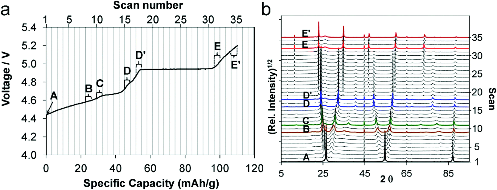 | ||
| Fig. 9 (a) First charge curve and (b) corresponding in situ XRD spectra (5–90° 2θ) of the graphite cathode during PF6− intercalation. Reproduced from ref. 129 with permission from American Chemical Society. | ||
| Anode: Li+ + e− ⇌ Li | (11) |
| Cathode: Cn + A− ⇌ Cn+A− + e− | (12) |
| Overall reaction: Li+ + A− + Cn ⇌ Li + Cn+A− | (13) |
| −eV = (μ0Li − μLi+) + (μCn+A− − μA−) | (14) |
 | (15) |
 | (16) |
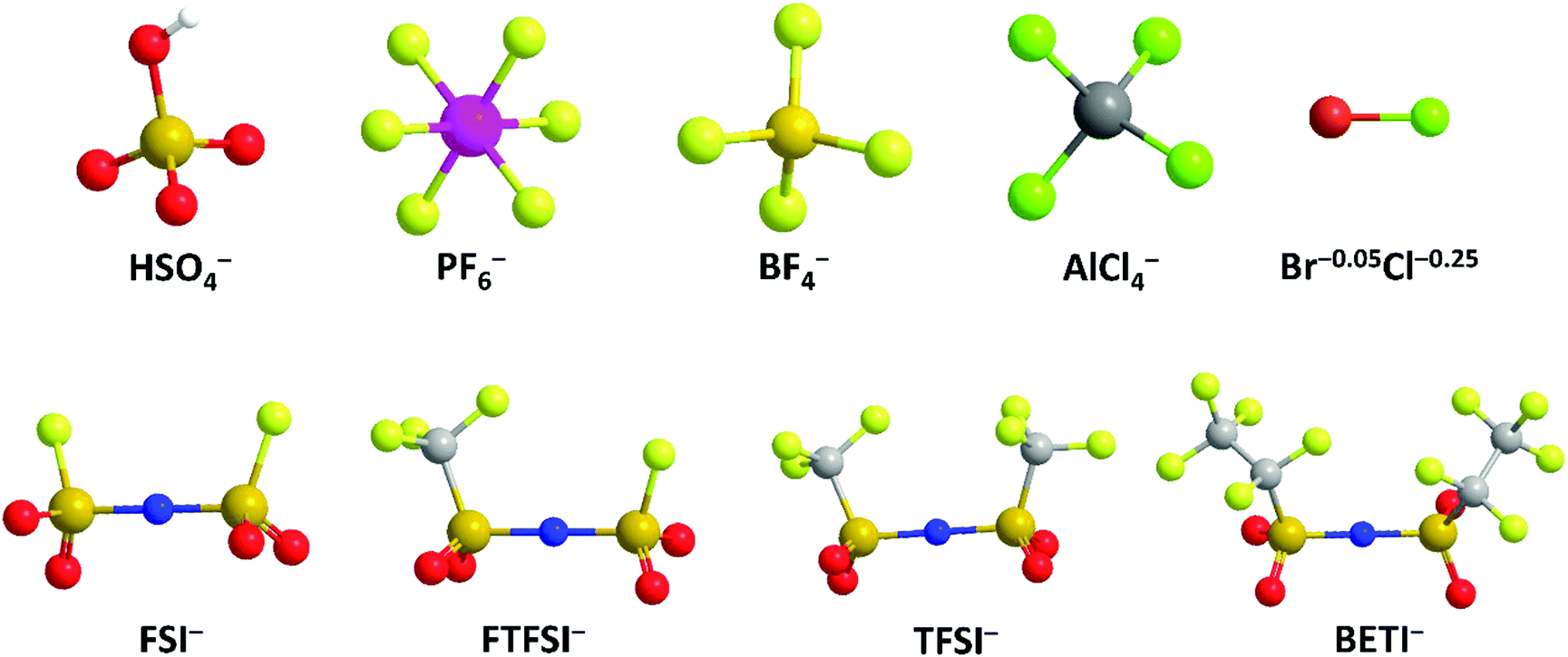 | ||
| Fig. 10 Schematic structure of different anions. | ||
(1) Anion type effect on anion intercalation. HSO4− is the first anion that was intercalated into graphite. As early as 1840, a H2SO4-based GIC was prepared.120 In 1938, Rüdorff and Hofmann27 discovered HSO4− intercalation into graphite from a concentrated acid electrolyte and proposed the first “rocking-chair” battery with graphite functioning as both anode and cathode. However, the use of a concentrated acid raises safety concerns for practical applications. And the proposed dual-graphite batteries showed limited working voltage (<0.8 V).
PF6− has been the most frequently explored anion for graphitic carbon cathodes since 1989, when McCullough et al.30 patented the first energy storage device based on a non-aqueous electrolyte and two carbonaceous electrodes. Owing to the high ionic conductivity and excellent electrochemical stability, LiPF6 has been adopted as the state-of-the-art electrolyte for commercial LIBs. At high potentials, PF6− forms F-containing passivation films on the Al or stainless steel current collector,177 suppressing unexpected side reactions. Dahn et al.130 first conducted in situ XRD to study the PF6− intercalation process into the graphite lattice and proved that a variety of staged phases existed; they measured the average layer spacing and PF6−-containing gallery height. A maximum stage-II’ phase with a stoichiometry of C8(PF6)0.5 was speculated, leading to a specific capacity of 140 mA h g−1 in the potential range of 3.5–5.45 V (vs. Li+/Li). With the assistance of various in situ characterization techniques, Read et al.129 investigated highly oriented pyrolytic graphite (HOPG) lattice expansion and revealed the solvent co-intercalation phenomenon during PF6− intercalation. Stage and composition progression of PF6−-GICs was proposed as follows: C24PF6 (stage-IV) → C24PF6 (stage-III) → C24PF6 (stage-II) → C20PF6 (stage-II) → C24PF6 (stage-I) → C20PF6 (stage-I). The final C20PF6 (stage-I) GIC at 5.20 V (vs. Li+/Li) corresponded to a specific capacity of 112 mA h g−1 and led to an expansion of 130%, as confirmed by in situ dilatometry measurements. Further, gravimetric measurements indicated that anion intercalation was accompanied by solvent co-intercalation at a ratio of ∼0.7 ± 0.2 solvent molecules per PF6−. Recently, it was evidenced with electrochemical quartz crystal microbalance (EQCM) that ethyl methyl carbonate (EMC) participated in the PF6− intercalation/deintercalation process by repeated release/feedback from/to the graphite cathode.164 To explore the molecular structure of PF6− in graphite, the DFT calculation was applied to simulate PF6− orientation between graphene sheets.178 A periodic unit cell constructed by two layers of 24 graphitic carbons and one PF6− showed that PF6− had a tilted octahedral shape.
Besides, imide anions (bis(trifluoromethanesulfonyl)imide (TFSI−), fluorosulfonyl-(trifluoromethanesulfonyl)imide (FTFSI−) and bis(fluorosulfonyl)imide (FSI−)) with better thermal/chemical stability and lower sensitivity towards hydrolysis than PF6− have been surveyed for graphitic carbon cathodes. Winter et al.179 pioneered TFSI− intercalation research in ionic liquid (IL) electrolytes. The upper cut-off potential for TFSI− intercalation into graphite was optimized (4.8–5.1 V vs. Li+/Li) to balance capacity and CE. The onset potential of TFSI− intercalation, especially in the first cycle, was dependent on temperature. Increasing the temperature (20 → 60 °C) resulted in an increased TFSI− uptake (30 → 100 mA h g−1). However, the self-discharge rate of the TFSI−-intercalated graphite cathode was also accelerated (1.3% per hour at 40 °C vs. 5% per hour at 60 °C). Further, after screening various graphite carbon cathodes, a maximum capacity of 115 mA h g−1 (C19–20TFSI) was achieved.180In situ XRD was conducted to probe the structure evolution of the graphite cathode during TFSI− intercalation.166,175 Stage-II and stage-I TFSI−-GICs could be achieved at 20 °C and 60 °C, respectively. In spite of no solvent co-intercalation issue in the IL system, the calculated di of TFSI−-intercalated graphite was in the range of 7.95–8.21 Å, which is higher than 7.77–7.83 Å for PF6−-intercalated graphite163 in a carbonate electrolyte. FTFSI− (3.9 × 6.5 Å), an imide anion with smaller size (3.9 × 6.5 Å) compared to TFSI− (3.9 × 8.0 Å), brought about higher capacities than FTFSI− at all surveyed upper cut-off potentials.181 However, the CE is problematic due to the inferior electrochemical stability of FTFSI−. The bis(pentafluoroethanesulfonyl) imide anion (BETI−; 5.1 × 9.4 Å) was also investigated.182 A high onset intercalation potential (5 V) and limited capacity (27 mA h g−1 at 3.4–5.6 V) were obtained, which can be mainly attributed to the large size of BETI−. A more detailed investigation was carried out on the anion size effect on anion intercalation behavior in IL electrolytes. It was found that the onset potential for anion intercalation is in the sequence of BETI− > FSI− > FTFSI− > (FSI−/TFSI−) > TFSI− > (TFSI−/FSI−), indicating that ion-pair formation and self-aggregation overrule the influence of the anion size on anion intercalation.183 FSI− anions were recently intercalated into the graphite cathode in a concentrated carbonate electrolyte, rather than in an IL.167 The FSI− intercalation was initialized at 4.6 V (vs. Li+/Li) and reached a stage-I GIC at 5.25 V (vs. Li+/Li). The maximum capacity achieved was 112 mA h g−1, corresponding to a stoichiometry of C20(FSI). The di and Δc of stage-I FSI−-GIC are 7.83 Å and 134%, which are similar to those of PF6−-GIC. Nevertheless, FSI− intercalation into graphite suffers from gradually decreased CE (99% → 93% within 300 cycles), which can be ascribed to anodic etching problems faced by many imide electrolytes.184,185
BF4− with quite a small size (2.6 × 2.6 Å), low molecular weight, and high thermal and hydrolytic stability (compared to PF6−) was a promising anion candidate for the graphitic carbon cathode.186 In the ethyl methyl sulfone electrolyte, BF4− intercalation occurs above 4.83 V (vs. Li+/Li), which is higher than 4.67 V for PF6− under the same condition.166 In the potential range of 3.4–5.4 V, BF4− intercalation into graphite led to a capacity of 97.6 mA h g−1, corresponding to a GIC stoichiometry of C23BF4. In situ XRD measurements further indicated a stage-I GIC and a di of 8.01 ± 0.05 Å. Although BF4− is smaller than PF6− in size, the di of BF4−-GIC is higher than that of PF6−-GIC, which can be explained by BF4− solvation states and solvent co-intercalation. In carbonate electrolytes (e.g. EMC) which work efficiently for PF6− intercalation into the graphite cathode, BF4− intercalation was found to be largely hindered with limited capacity (6 mA h g−1 at 3–5 V) yet high polarization over 1 V.187 The strong attraction between Li+ and BF4− clusters and the special anion solvation states were believed as the main reasons. By introducing the additional trimethyl phosphate solvent, Wang et al.188 facilitated BF4− intercalation into graphite, leading to an enhanced capacity (26.7 mA h g−1) and suppressed polarization (0.3–0.4 V).
Metal chlorides (e.g. UCl5 and AlCl3), as an important family of intercalants, were intercalated into graphite as early as 1973 by a solution method.170 It was not until 2015 that electrochemical AlCl4− intercalation into graphitic carbon was first accomplished by Dai and coworkers in an IL electrolyte composed of AlCl3/1-ethyl-3-methylimidazolium chloride (EMImCl).170 A 3D graphene foam cathode was used as the cathode and a capacity of 66 mA h g−1 was achieved. Ex situ XRD suggested the formation of a stage-IV AlCl4−-GIC under a fully charged state. A broad shoulder was noticed in the XRD pattern of the fully discharged sample, indicating irreversible change of stacking between graphene layers or trapped intercalants. In situ Raman spectroscopy revealed that, during AlCl4− intercalation, the graphite G band at 1584 cm−1 diminished and split into a doublet (E2g2(i) mode at 1587 cm−1 and E2g2(b) mode at 1608 cm−1), and eventually evolved into a sharp new peak at 1636 cm−1. E2g2(i) was attributed to vibrations of carbon atoms in the interior of graphite layer planes, while E2g2(b) was derived from vibrations of carbon atoms in the bound graphite layers adjacent to intercalant layer planes. On replacing graphene foam by natural graphite, the capacity was largely enhanced to 110 mA h g−1.189 Reversible oxidation/reduction of carbon was verified by X-ray photoelectron spectroscopy (XPS) and X-ray adsorption spectroscopy (XAS). The geometry structure of AlCl4− between graphene layers was further simulated by DFT and first-principles calculations. The four bond angles of AlCl4− were changed to 107.8°, 106.8°, 110.1° and 107.6°. It means that AlCl4− was distorted/flattened from the tetrahedron structure. Moreover, the temperature has a significant impact on the structure of the AlCl4−-GIC. It was found that at −10 °C, AlCl4− intercalation into graphite led to a stage-III GIC, rather than a stage-IV GIC at room temperature.168 At the same time, a new charge/discharge plateau was observed at 2.5 V (vs. Al2Cl7−/Al) in the charge–discharge profiles of the graphite cathode. The di of stage-III AlCl4−-GIC was 9.59 Å, as indicated by theoretical modeling. AlCl4− intercalation into graphitic carbon can additionally occur in inorganic ILs like AlCl3–urea190 and AlCl3–NaCl–KCl (at 393 K).191
| LiBr + Cn ⇌ CnBr + Li+ + e− (4.0–4.2 V) | (17) |
| LiCl + CnBr ⇌ CnBrCl + Li+ + e− (4.2–4.5 V) | (18) |
(2) Solvent role in anion intercalation. Solvent, an important component of liquid electrolytes, plays a key role in dissolving active salts and offering a medium for charge carrier migration. The interaction between anions and solvent significantly influences anion intercalation behavior and therefore the electrochemical performance of graphitic carbons. An ideal electrolyte should possess a wide electrochemical stability window, high ionic conductivity, low viscosity, excellent thermal stability, low toxicity and ability to form a passivation film to prevent continuous electrolyte decomposition.192–194
Carbonate electrolytes have been frequently utilized for the graphitic carbon cathode due to their high dielectric constant, low viscosity, and excellent electrochemical stability.195 Ethyl carbonate (EC), an important SEI forming agent for LIBs, largely prevents anions from intercalating into graphitic carbon196 due to its strong solvation power against PF6−, which makes it difficult for PF6− to be de-solvated for intercalation. However, such strong solvation power of EC is necessary to dissolve salts with limited solubility or to achieve concentrated electrolytes. Therefore, EC is still used for NaPF6,178,197–199 KPF6,200,201 Ca(PF6)2202 and KFSI167-based electrolytes. In these electrolytes, anion intercalation will be accompanied by EC co-intercalation. Lu with his colleagues203 investigated the interaction between PF6− and different solvents, including EMC, dimethyl carbonate (DMC), EC, PC, 1,3-dioxolane (DOL) and dimethyl ether (DME). The van der Waals forces between PF6− and DMC or EMC are positive while they are negative for PF6− with DME, DOL, EC and PC, indicating repulsion and attraction, respectively. Among these solvents, EMC is closest to the balance site, leading to the highest anion intercalation capacity in the range of 3–5 V vs. Li+/Li. In PC solvent, the onset potential for PF6− intercalation moves to a higher value (4.7 V vs. Li+/Li), which is higher than 4.4–4.5 V vs. Li+/Li in EMC solvent and results from the strong interaction of PF6− with PC. Besides, it is found that DMC can lower the anion intercalation potential plateau, indicating enhanced intercalation kinetics.202
To further enhance the oxidative stability of carbonate electrolytes, F-containing carbonate is adopted due to its low highest occupied molecular orbital (HOMO) energy.204,205 Moreover, F-containing carbonate can contribute to the formation of a F-rich interphase, which is beneficial for both cathode and anode. Read et al.206 prepared an electrolyte of 1.7 M LiPF6 in monofluoroethylene carbonate (FEC)–EMC with 5 mM tris(hexafluoro-iso-propyl)phosphate. PF6− intercalation works efficiently in this electrolyte up to 5.2 V with a high average CE of 96%. It is worth noting that in carbonate electrolytes, solvent co-intercalation into graphitic carbon cathodes appears to be inevitable, but it does not necessarily cause graphitic carbon exfoliation as happened in the Li-PC207 system for the graphite anode.
In addition, ILs with broad electrochemical stability windows, high safety properties (low volatility and low flammability), a broad liquid range and high thermal stability are attractive alternatives to carbonate solvents. As a typical example, TFSI−, which severely corrodes Al current collectors in dilute carbonate electrolytes, however, performs stably up to 5.1 V (vs. Li+/Li) in N-butyl-N-methylpyrrolidinium bis(trifluoromethanesulfonyl)imide (Pyr14TFSI) with 1 M LiTFSI.165,179 Good compatibility with Al current collectors was noticed for BETI−, FTFSI− and TFSI− in ILs, which originates from the poor solubility of initially formed corrosion products in the ILs, thus generating a protective layer on the Al surface.208,209 Regarding FSI-, as the products [Al(FSI)x] can be dissolved in IL, no protection layer can be formed, resulting in continuous Al etching.210 Therefore, BETI−, FTFSI− and TFSI− intercalation into graphitic carbon in IL electrolytes was quite efficient without obvious side reactions. Nevertheless, the high viscosity of ILs may be a concern for low ionic conductivity and limited intercalation kinetics compared to carbonate electrolytes, especially at low temperature (≤RT). The salt solubility in ILs also seems to be limited (≤1 M), making it difficult to prepare concentrated electrolytes.
(3) Electrolyte concentration effect on anion intercalation. Unlike in rocking-chair alkaline metal-ion batteries, electrolyte concentration has a profound effect on anion intercalation behavior. Within a Li//graphite cell, our group noticed that increasing LiPF6 concentration (1 → 4 M) in EMC not only reduced the onset potential (4.45 → 4.25 V) of PF6− intercalation into graphite but also increased the specific capacity (67 → 98 mA h g−1, Fig. 11), which can be explained by that under a high concentration electrolyte, most solvent molecules are coordinated/shared with/by adjacent cations and anions. This means that the solvent coordination number of anions decreases. Therefore, the desolvation energy of anions in a concentrated electrolyte is lower than that in a dilute electrolyte, leading to reduced anion intercalation potential. Similar phenomena were noticed in LiPF6 FEC/DEC,211 LiTFSI DMC,212 LiPF6 methyl propionate213 and even AlCl3-EMImCl214 electrolytes.
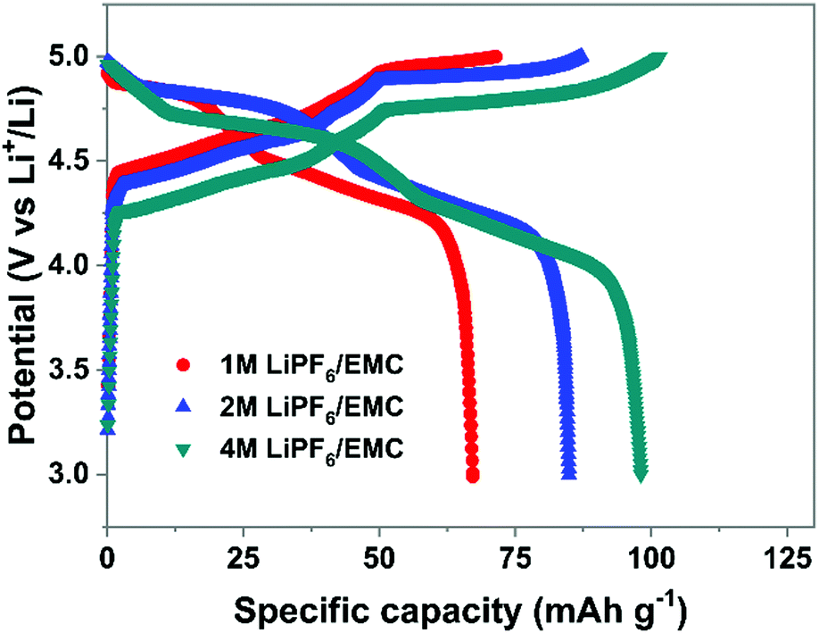 | ||
| Fig. 11 Charge–discharge profiles of the graphite cathode in different concentration electrolytes. Li//graphite half cells were used. Electrolytes are 1–4 M LiPF6 in EMC. The current density is 100 mA g−1. | ||
On the other hand, high concentration electrolytes can enhance the reversibility of anion intercalation by suppressing side reactions (anodic dissolution/etching). The recently reported Br−0.05Cl−0.25-GIC172 can only be prepared in a highly concentrated aqueous electrolyte; otherwise side reactions like water oxidation will take place and Br− and Cl− are impossible to intercalate into graphitic carbon. Another example is that the dilute LiTFSI carbonate electrolyte suffers from the Al etching problem, which was well resolved by increasing LITFSI concentration. A high oxidation stability of up to 5.6 V was obtained in 2.7 M LiTFSI/DEC,212 which is attributed to the lack of free solvent molecules, thereby stabilizing the Al current collector.215 The concentrated electrolyte strategy is kinetically effective to enhance the electrolyte oxidative stability, which performs well in rocking-chair batteries.216,217 Because electrolyte concentration remain constant during battery operation. For graphitic carbon cathode working under the anion intercalation mechanism, it remains to be confirmed whether anodic etching will reappear once most salts are consumed during charging, especially under lean electrolyte conditions.
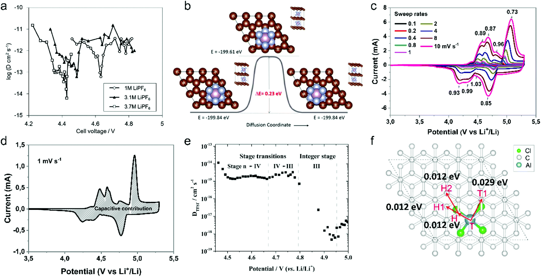 | ||
| Fig. 12 (a) Diffusion coefficient of PF6− into graphitic carbon calculated using GITT as a function of cell voltage during the charging process. (b) The Cl-NEB calculation result for estimating the diffusion energy barrier along the 〈100〉 direction. Reproduced from ref. 218 with permission from American Chemical Society. (c) CV curves of graphite cathodes at various sweep rates. (d) Separation of the capacitive and diffusion currents of the graphite cathode at a scan rate of 1 mV s−1. Reproduced from ref. 221 with permission from Wiley-VCH. (e) Representation of the (apparent) diffusion coefficient of the TFSI anion in graphite in relation to the charging potential and estimated stage of the acceptor-type GIC. Working electrode: KS6 graphite; reference/counter electrodes: lithium metal; 2nd cycle, operating temperature 20 °C. Reproduced from ref. 223 with permission from Elsevier. (f) Four elementary diffusion pathways for AlCl4− in the graphite denoted by arrows connecting two sites. Reproduced from ref. 226 with permission from American Chemical Society. | ||
Our group investigated PF6− intercalation kinetics in graphite flakes by a CV method (Fig. 12c),221 where a strong binder was used to address the electrode disintegration problem. Four main pairs of redox peaks corresponding to reversible formation of different stage PF6−-GICs were clearly observed in the CV curves of the graphite cathode. The current increased along with the scan rate without generating much polarization (peak shift), behaving like pseudocapacitive materials. According to eqn (8),222 the b values of each redox peak were estimated to be approaching 1, implying that PF6− intercalation into graphite is not a diffusion-limited process. The b value of the oxidation peak derived from phase transition (stage-II to stage-I) is found to be lower than others, suggesting relatively slow PF6− intercalation in this range. This result fits very well with diffusion coefficient data attained from GITT measurements. The capacitive contribution was quantitatively determined by eqn (9). At 1 mV s−1, 93% capacity is from capacitive-like intercalation (Fig. 12d). Our results suggest that kinetically PF6− intercalation into graphite displays capacitor-like (pseudocapacitive) characteristics.
Winter et al.223 conducted a comprehensive study on TFSI− intercalation kinetics into various graphitic carbons in IL electrolytes. The specific discharge capacity strongly depends on the “non-basal plane” surface area of graphite at <40 °C, which can be related to additional overpotential evolution close to the formation of intercalation stages of the graphite host. Due to large anion size, the diffusion coefficient (2 × 10⁻¹⁵ cm2 s−1 at 20 °C, Fig. 12e) of TFSI− within the graphite lattice is lower than that for PF6−. At operating temperatures >50 °C, the capacity increases remarkably from 60 mA h g−1 to 100 mA h g−1 owing to the presence of stage-I GIC enabled by further overpotential reduction. With respect to AlCl4−, the energy barrier for AlCl4− diffusion in graphitic carbon calculated using the NEB method is in the range of 0.021–0.028 eV,224 much lower than 0.3–0.4 eV for Li diffusion in graphite.225 Considering a large di of 9.25 Å for AlCl4−-GIC, Sun et al.224 suggested a configuration with 3-fold rotation symmetry about the direction normal to the graphite basal plane, even though its energy is higher than that of the configuration with 2-fold rotation symmetry. Lu et al.226 performed first-principles calculations on AlCl4−-GICs and revealed that AlCl4− prefers single-layer tetrahedron geometry between graphene sheets with AB stacking manner preserved. Diffusion energy barriers of AlCl4− were determined as 0.012–0.029 eV (Fig. 12f), leading to a high diffusion coefficient in the order of 10−4 cm2 s−1 and fast AlCl4− intercalation into graphitic carbon.
The first key parameter for graphitic carbons is graphitization degree (GD), which is defined as the extent of the transformation of nongraphitic carbon materials into a perfectly ordered graphitic structure, can be expressed by eqn (19),227 where 0.3440 nm and 0.3354 nm are the interlayer spacing of non-graphitic carbon and perfectly stacked graphite, respectively. d002 is the interlayer spacing of the studied carbon materials. Ishihara et al.228 conducted electrochemical PF6− intercalation experiments on various carbon materials, and noticed that the capacity of PF6− intercalation increases with decreasing d002 (enhancing GD). To further reveal the structure–electrochemical property correlation, a detailed investigation was carried out on carbon materials with controlled GD. Under a high temperature treatment (2200–2800 °C), non-graphitic carbons gradually evolve into graphitic ones with d002 decreased from >0.3415 nm to 0.3360 nm while GD enhanced from 30% to 90%.229 It was found that the electrochemical performance of the carbon cathode is directly dependent on the GD, where the specific capacity increases along with GD at a rate of ∼0.3 mA h g−1 per GD and a maximum discharge capacity of 100 mA h g−1 was achieved in a LiTFSI/IL electrolyte. The voltage efficiency was found to be improved in the carbon cathode with a high GD. For AlCl4−, a similar phenomenon was recognized. Kish graphite flakes with the smallest d002 showed a typical staging intercalation/deintercalation process and the highest capacity, while the amorphous carbon presents a linear charge–discharge curve and the lowest capacity.230
 | (19) |
800 S m−1 was obtained. As a result, the few-layer graphene enabled both PF6− and AlCl4− intercalation for DIBs and AIBs, achieving high capacity over >120 mA h g−1 even at a high rate.230 More investigation is required to confirm the effect of other dopants (like B, N, P) on anion intercalation behavior in graphitic carbon.
Particle size is another important parameter for graphitic carbon, where two different planes, basal plane and edge plane, exist. The smaller the size, the more the edge plane exposed. Considering the “entrance” feature of the edge plane for guest ion intercalation, more edge exposure indicates a short diffusion path and a fast intercalation rate, leading to high capacity and rate capability as evidenced by the graphite anode for LIBs.236 For the anion intercalation process, the graphite particle size effect was studied in TFSI−-based IL electrolytes.180,237 Small-size graphite indeed exhibited higher capacity at 20 °C, even though the electrode conductivity decreased with particle size due to the increased number of high-resistance particle surface contacts.238 However, this effect gradually blurred at 60 °C, which is explained by the fact that the enhanced ion diffusion at elevated temperature prevails the effect of entrance sites present at low temperature. In addition, the irreversible charge capacity of the graphite cathode in the first cycle was found to be independent of graphite size (surface area), which is different from the SEI formation process for the graphite anode.239 No correlation between the first cycle efficiency and the particle size (specific surface area) of graphitic carbon could be concluded. The anion intercalation stability was proved to be better in large-size graphitic carbon (graphite, graphene) than small-size one.238,240
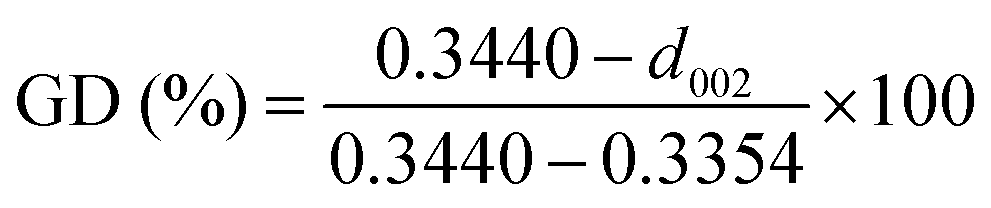
The thickness of graphitic carbon with a compact stacking structure can be tailored by exfoliation or introducing pores between graphitic carbon layers. Thin graphitic carbon is expected to possess enhanced ion diffusion and to better alleviate volume expansion. It is reported that the few-layer graphene cathode exhibited a much higher rate than the graphite counterpart for AlCl4− intercalation/deintercalation.240 To facilitate fast AlCl4− diffusion inside graphitic carbon, vertically aligned pores were introduced into compact pyrolytic graphite foil via AlCl4− intercalation followed by thermal expansion and electrochemical H2 expansion (Fig. 13a),97 avoiding irreversible oxidation of graphite and defect introduction. The resultant monolithic vertically aligned graphitic structure afforded complete AlCl4− intercalation within 18 s (60 mA h g−1 at 12 A g−1) and remained stable for over 4000 intercalation–deintercalation cycles.
 | ||
| Fig. 13 (a) The SEM image of three-dimensional graphite foam. Reproduced from ref. 97 with permission from Wiley-VCH. (b) Illustration of tri-continuous and tri-high design for a desired graphene film. Reproduced from ref. 169 with permission from AAAS. | ||
Besides, the morphology of graphitic carbon also plays a critical role in anion intercalation. The exposure state (well exposed or blocked) of the edge plane and basal plane (bent or not) of graphitic carbon may influence the anion intercalation behavior. The comparison between potato-like graphite particles and graphite flakes indicates that potato-like graphite with bent graphene layers showed a reduced ability for AlCl4− intercalation (65 mA h g−1vs. 95 mA h g−1 for graphite flakes),230 which is different from the Li+ intercalation case. Three-dimensional graphene foam that was made via chemical vapor deposition possessed well interconnected pores and led to a maximum capacity of 70 mA h g−1.170 The graphene foam cathode enabled fast yet durable AlCl4− intercalation/deintercalation, affording a charge time of 1 minute and stability over 7500 cycles. Recently, a thin graphene film was reported as a high-rate anion intercalation host, which possessed high-quality, high-orientation graphene and a high channeling local structure as well as a continuous electrically conductive/electrochemically active matrix and ion-conducting channels (Fig. 13b).169 The graphene film delivered a high capacity of 120 mA h g−1 (stage-III AlCl4−-GIC) at an ultrahigh current density of 400 A g−1 and a long cycle life of 0.25 million cycles.
4. Energy storage devices based on ion-intercalative carbon
4.1 Cation-intercalation carbon anode for ‘rocking-chair’ batteries
In this part, we mainly survey the recent developments in the structure design/modification of carbon-based materials, and the emerging battery devices based on these carbon materials. It should be pointed out that most of the research about carbon anodes focused on the correlation between microstructure and charge-storage performance, which mainly relies on the half-cell tests rather than implantation in full-cell devices. Therefore, particular efforts have been put on emerging carbon structures by associating their morphological properties with their electrochemical behavior.(1) Ordered carbon anodes. In spite of the great success of graphite anodes in commercial LIBs, the prospect of carbon anodes in LIBs is still obstructed in terms of the lower theoretical capacity of graphite compared with other conversion- or alloy-type anodes (e.g. silicon, Sn, transition metal oxides/dichalcogenides).36 In this context, extensive efforts have been devoted to constructing fantastic carbon structures with favorable metrics, such as high specific surface area, hierarchical porosity, and doping with heteroatoms/functional groups.
The early studies on Li-ion storage carbon anodes mainly focused on ordered carbon materials, which have been well documented in some previous review literature.37,242–244 Most of the studies rely on constructing hierarchical structures with ordered carbon building blocks (e.g. 2D graphene, 1D CNTs) to achieve high specific capacity, as such kind of structures promote the access of the electrode surface to the electrolyte.245–255 For example, graphene was employed early to construct a binder-free anode for LIBs by directly drop-casting the graphene ink on Cu foil.256 Hassoun et al.257 reported full LIBs with graphene anodes and lithium ion phosphate cathodes delivering a high specific capacity of 165 mA h g−1 and an energy density of 190 W h kg−1. On the other hand, the ion mobility of 2D materials is considered as the key factor that limits their rate performance.258 To improve the compact geometry of carbon materials and enhance their accessible volume, creating ordered pores was also widely investigated. For example, Zhao and co-authors251 prepared a kind of mesoporous graphene nanosheet through controllable assembly of monomicelles and heterogeneous nucleation processes. Phenolic resol molecules were assembled with a Pluronic triblock copolymer, forming spherical monomicelles and depositing on the channel walls of an anodic aluminum film. After pyrolysis at 700 °C for 2 h in argon, the mesoporous graphene nanosheets were synthesized. The mesoporous graphene nanosheets exhibited a low coulombic efficiency of 29.4% in the first cycle, with a discharge specific capacity of 3535 mA h g−1 and a charge specific capacity of 1040 mA h g−1 at 100 mA g−1. In 2010, our group designed a kind of graphene-based mesoporous nanosheet with a sandwich structure.241 As shown in Fig. 14a, graphene-based mesoporous silica sheets were synthesized by using negatively charged graphene oxide to electrostatically adsorb cationic cetyltrimethyl ammonium bromide and annealing in Ar at 800 °C for 3 h. The graphene-based mesoporous nanosheets were further synthesized by using graphene-based silica sheets as the templates and sucrose as the carbon source. The SEM image (Fig. 14b) revealed the 2D morphology of the graphene-based mesoporous carbon materials. The specific surface area was measured to be 910 m2 g−1 with the presence of abundant micro- and meso-pores (Fig. 14c). The first-cycle reversible capacity of this graphene-based mesoporous carbon nanosheet reached up to 915 mA h g−1 (Fig. 14d).
 | ||
| Fig. 14 (a) Schematic of the formation process for graphene oxide based mesoporous silica sheets. (b) SEM and (c) nitrogen adsorption/desorption isotherm of the obtained graphene-based mesoporous nanosheets. (d) First and second cycles of galvanostatic discharge/charge curves of the graphene-based mesoporous nanosheets. Reproduced from ref. 241 with permission from Wiley-VCH. | ||
Besides, vertically aligned MWCNT arrays were obtained on various catalytic substrates (e.g. graphene paper,249 stainless steel,250 copper,245 nickel foil,254 silicon252) through CVD methods. The reversible specific capacity at a low rate ranged from 350 to 1455 mA h g−1. For example, Li et al.249 fabricated a novel kind of free-standing graphene paper with vertically aligned MWCNTs grown on the surface. A reversible capacity of 290 mA h g−1 at 30 mA g−1 was reached. By using a similar two-step process, Choi's group245 grew MWCNT arrays on a copper current collector through a two-step process of sputtering catalytic Ti and Ni on Cu foil and MWCNT growth by a CVD method. At a low current density of 38 mA g−1, the first discharge and charge capacity of the obtained electrode were 2500 and 1455 mA h g−1, indicating the first-cycle CE of 58%. Even at a very large current density of 1116 mA g−1, the reversible specific capacity of the vertical aligned MWCNT arrays reached 767 mA h g−1.
(2) Disordered carbon anodes. Developing disordered carbon materials by searching suitable carbon-rich precursors represents another important development trend in high-capacity carbon anode materials.260 In this research direction, the employed precursors play a crucial role in determining the structural properties of hard carbon materials. So far, the employed precursors mainly include biomass (e.g. egg white,261 sheep bone,262 Portobello mushroom,263 filter paper264,265) and synthetic carbon-rich compounds (zeolitic imidazolate framework-8,266 ethylenediaminetetraacetic acid manganese disodium salt hydrate,267 alkyl surfactant sulfonate anion-intercalated NiAl-layered double hydroxide,268 polyacrylonitrile (PAN),259,269–272 phenol resin,273,274 and hexa-peri-hexabenzocoronene275). One of the targets for these studies is to find green and low-cost precursors for large-scale production of hard carbon materials with a high specific surface area. For example, electrospun PAN based nanosized fibers were widely used as carbon precursors. Kim et al.270 directly used pure PAN fibers as the precursor to get carbon nanofibers for the LIB anode. As revealed, the carbon fibers obtained at 1000 °C depict an optimal reversible specific capacity of 450 mA h g−1 at 100 mA g−1, outclassing the carbon fibers obtained at 700 °C (300 mA h g−1) and 2800 °C (130 mA h g−1).270 To create porosity in the carbon fibers, poly(methyl methacrylate)259,271 and poly-L-lactic acid272 were added into the PAN based fiber precursor. During the thermal decomposition, poly(methyl methacrylate) or poly-L-lactic acid can produce a complex gas as the soft template, which induces the massive formation of large pores.
Apart from the direct pyrolysis of organic precursors for hard carbon materials, additional templates (e.g. ZnCl2 salt,276,277 SiO2,274,278,279 MgO,280 Ni259) were also widely used to create more mass transport channels, which can significantly boost the specific capacity and rate capability of hard carbon materials. For example, our group demonstrated a kind of hollow carbon sphere by using hexadodecyl-substituted hexa-peri-hexabenzocoronene (HBC-C12) as the precursor and eyelike silica/space/mesoporous silica as the template.275 The template was mixed with the tetrahydrofuran solution of HBC-C12 to allow the impregnation of HBC-C12 into the pores of the template. Afterwards, the samples were annealed in Ar at 700 °C for 5 h. After etching of silica in a NaOH solution, hollow carbon spheres were obtained, showing a specific surface area of 260 m2 g−1. Remarkably, the reversible specific capacity of the hollow carbon spheres reached 600 mA h g−1. In addition, Chen et al.259 first prepared PAN/Ni(Ac)2/poly(methyl methacrylate) composite nanofibers by employing a coaxial electrospinning approach. The pyrolysis of these nanofibers was conducted at 700 °C under a vacuum of around −750 torr for 6 hours. During the pyrolysis, the strong stress induced by the vacuum condition cracked the graphitic layer, guiding the diffusion of Ni to the carbon fiber surface (as revealed in Fig. 15a). After the removal of Ni, the porous carbon fibers were obtained, featuring rich hollow tunnels (Fig. 15b). The Brunauer–Emmett–Teller (BET) results confirm the important role of poly(methyl methacrylate) in producing pores with diameters of 3.2, 9, 25, and 40 nm (Fig. 15c). Meanwhile, the removal of Ni particles further increases the number of pores with a size of ∼63 and 120 nm. Interestingly, the porous carbon nanofibers demonstrated excellent Li-ion storage performance with a high reversible capacity of 1560 mA h g−1 (corresponding to a volumetric capacity of 1.8 A h cm−3) at 100 mA g−1 (Fig. 15d). At a large current of 10 A g−1, the reversible specific capacity of the porous carbon nanofibers remained at 380 mA h g−1 (Fig. 15e). Moreover, the porous carbon nanofibers show excellent cycling stability with a slight capacity decay after 2000 charge/discharge cycles at 10 A g−1 (Fig. 15f).
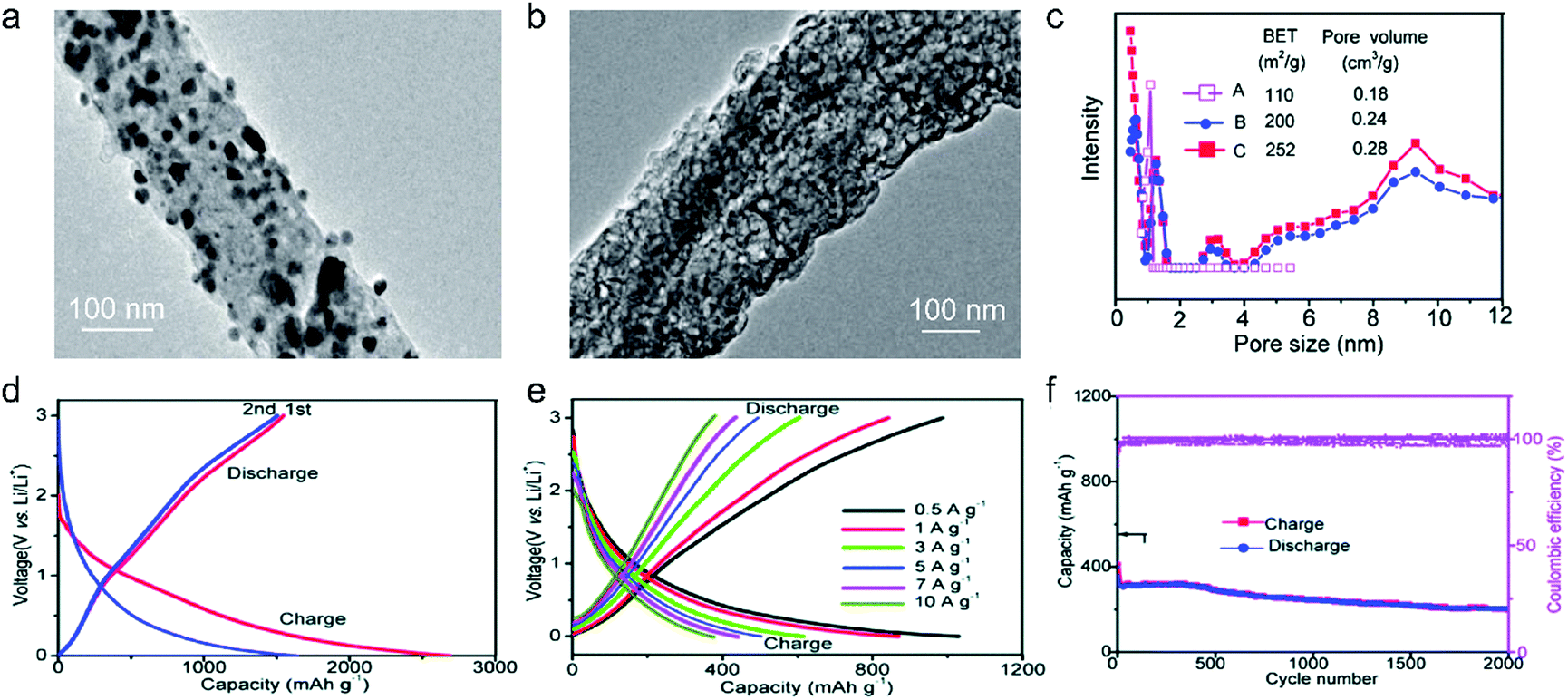 | ||
| Fig. 15 TEM images of (a) N-doped carbon/Ni nanofiber and (b) porous N-doped carbon nanofiber. (c) Pore size distribution of sample A by calcining PAN/Ni(Ac)2 composite nanofibers, sample B by calcining PAN/PMMA/Ni(Ac)2 composite nanofibers, and sample C from sample B after Ni diffusion. (d) Initial two charge–discharge voltage profiles of the obtained porous carbon nanofibers cycled at a current density of 100 mA g−1. (e) Charge–discharge profiles at various rates from 500 mA g−1 to 10 A g−1. (f) Cycling performance at a current density of 10 A g−1. Reproduced from ref. 259 with permission from Royal Society of Chemistry. | ||
(3) Heteroatom-doped carbon anodes. In addition, heteroatom doping represents an important strategy for further boosting the Li-ion storage ability of carbon anodes. It can induce the formation of topological defects in carbonaceous materials, which is beneficial for the diffusion and insertion of Li-ions into carbon structures. N-Doping has been the most common method, which was initially studied in ordered carbon materials (graphene52,266,281–285 and CNTs286). Cao et al.281 performed first-principles calculations to evaluate the Li-ion storage properties of different N-doped graphene, including graphitic, pyridinic and pyrrolic N-doped graphene. They demonstrated that the adsorption of Li+ on pyridinic N-doped graphene was the most stable one among the three kinds of graphene, while graphitic N-doped graphene was the least stable one. The calculated specific capacity of pyridinic N-doped graphene can be up to 1262 mA h g−1. Ajayan's group52 synthesized N-doped graphene films through a CVD method with acetonitrile as the precursor. Compared with the pure graphene film, the N-doped graphene films demonstrated a 1-fold increase in their reversible capacity. The authors assigned the enhanced capacity to the enriched topological defects induced by the doped N atoms, which promote the Li intercalation properties. Moreover, high-level N doping can be realized by thermally treated carbon materials together with additional N resources, such as melamine282,284,285 and ammonia.283 For example, Cai et al.282 mixed pristine graphene with melamine together, and thermally treated the mixture at a temperature of 700 °C under an Ar atmosphere. The N-doping level in the obtained N-doped graphene reached more than 7%, which endowed the N-doped graphene anode with a high reversible capacity of 1123 mA h g−1 at 50 mA g−1 and 241 mA h g−1 at 2 A g−1. On the other hand, N-doped disordered carbon materials can be easily obtained by selecting N-containing precursors. These precursors can be N-containing polymers,259,287–289 metal–organic frameworks,266 and biomass.278,290
Heteroatoms, like P and S, were also doped into carbon materials to boost the Li-ion storage ability. Different from the N atom having a similar diameter to the C atom, P and S atoms have much larger diameters than the C atom.291 Therefore, P and S dopants can expand the distance between the neighbor carbon layers, thus promoting the migration of Li ions within carbon materials. Hou's group292 carried out the first study of P-doped graphene for Li-ion storage. They synthesized P-doped graphene by thermally annealing the mixture of graphite oxide and triphenylphosphine under an Ar atmosphere. As revealed, the specific capacity of P-doped graphene (460 mA h g−1 at 100 mA g−1) greatly outweighed that of pure graphene (280 mA h g−1 at 100 mA g−1). Zhang et al.268 reported the synthesis of S-doped mesoporous carbon materials by the pyrolysis of alkyl surfactant sulfonate anion-intercalated NiAl-layered double hydroxide. The reversible specific capacity of the obtained S-doped mesoporous carbon reached an outstanding value of 1157 mA h g−1 at 100 mA g−1. Moreover, to reach a synergistic effect, researchers also fabricated dual-doped carbon materials, like N,S-codoped and N,P-codoped carbon materials.293–296 These materials all show great potential as large-capacity and highly stable anode materials for LIBs.
(4) Others. To go beyond the well-known ordered and disordered carbon structures, theoretical calculations were performed to predict the brand-new carbon structures for Li-ion storage. In 2016, Wang et al.297 predicted a topological semimetal all-sp2 bonding carbon structure consisting of a 16-atom body-centered orthorhombic unit cell (defined as bco-C16). The configuration of bco-C16 can be considered as a three-dimensional modification of graphite in AA stacking, which is made up of linear chains of benzene linked by ethene-type planar π-conjugation. Liu with his colleagues298 used DFT calculations to identify the favorable Li-ion storage capability (558 mA h g−1) of bco-C60 with a feasible Li-intercalated compound (LiC4). Fig. 16a shows the possible Li-ion storage sites for bco-C16. Five stable intermediate configurations were simulated, corresponding to LixC4 (x = 0.167, 0.25, 0.5, 0.667, and 0.75). The binding energies calculated for all these five intermediates are negative, revealing that Li ions can be stably stored in the bco-C16 structure (Fig. 16b and c). The simulated voltage profile reveals three main voltage platforms within the voltage range of 0.63–0.05 V and an average voltage of 0.25 V. Recently, Wang et al.299 simulated a new 2D planar carbon allotrope, made up of 5-8-5 carbon rings. They revealed that such a structure principally depicts a high Li-ion adsorption capacity of 1487 mA h g−1 (Li4C6), a low open circuit voltage of 0.45 V, and a low Li-ion diffusion energy barrier (less than 0.55 eV). All these theoretical efforts provide an insightful understanding to further stimulate the design and synthesis of new carbon structures for Li-ion storage.
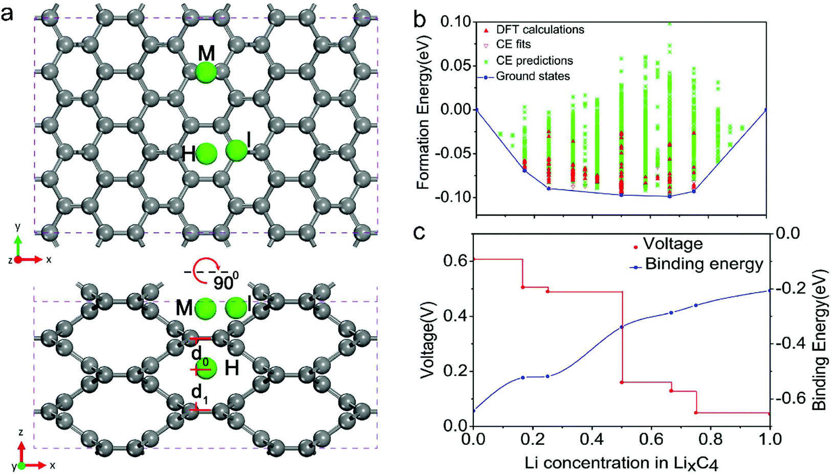 | ||
| Fig. 16 (a) Structure of bco-C16 and the schematics of the possible Li-ion absorption sites in top and side view. (b) Formation energies predicted for the 150 different Li configurations with 5 stable intermediate phases. (c) Corresponding voltage profile (marked in red) and binding energy profile (marked in blue) calculated along the minimum energy path. Reproduced from ref. 298 with permission from United States National Academy of Sciences. | ||
(1) Ordered carbon anodes. As stated earlier, pristine graphite closes the door for Na-ion storage, owing to the difficult Na+ intercalation into carbon bilayers. Considering the open structure and good electronic conductivity, graphene-based materials as NIB anodes attracted researchers’ interest.149,151,300–304 Wang et al.151 synthesized rGO and studied its Na-ion storage capability in an electrolyte of 1 M NaClO4 in PC. Compared with graphite materials, rGO presents a larger interlayer distance (0.36–0.37 nm) and a more disordered structure, which favors the intercalation of Na+ into rGO. The specific capacity of rGO reached 174.3 and 93.3 mA h g−1 at 40 and 200 mA g−1, respectively. David and Singh300 investigated the NIB anodes made up of thermally reduced GO. rGO based materials annealed under an Ar atmosphere showed the optimal Na-ion storage performance at a thermal treatment temperature of 500 °C. The specific capacity reached 140 mA h g−1 at a current density of 100 mA g−1. When the thermal treatment temperature was above 500 °C, the obtained rGO anodes exhibited an apparent capacity decrease. The authors attributed this capacity decay to the decreased interlayer spacing and the increased ordering level of the graphene sheets. Chang's group301 synthesized a holey graphene material by thermally reducing GO at a low temperature of 300 °C with a fast temperature increase rate (>100 °C s−1). The resultant rGO allowed the retention of oxygen-containing functional groups on the graphene surface, which not only provided additional redox sites but also expanded the interlayer spacing. For comparison, the rGO sample was also fabricated at a high temperature of 1000 °C. Clearly, the rGO electrode prepared under 300 °C (220 mA h g−1 at 30 mA g−1) delivered a significantly higher specific capacity than the rGO electrode prepared under 1000 °C (147 mA h g−1 at 30 mA g−1). Moreover, improvement in the Na-ion storage ability of graphene materials was also demonstrated by strategies like hydrogenation,302 constructing crumpled morphology304 and 3D foams.305 The improved performance can be explained by the increased accessible surface area, the improved conductivity, and the favorable Na+ diffusion.
(2) Disordered carbon anodes. Although graphene materials achieved great improvement in the ability of storing Na+, particularly when compared with graphite materials, the limited specific capacity of graphene-based anodes still cannot fulfill the increasing capacity demand for SIBs. Following the developing roadmap of carbon-based LIB anodes, the development of new carbon structures for NIB anodes has been recently focused on the exploration of large-capacity disordered carbon materials. Synthesizing hard carbon materials from biomass materials is extremely attractive, as most of biomass materials are abundant, low-cost, and renewable. Typically, biomass derived carbon materials were fabricated by directly annealing pre-dried biomass materials under an inert atmosphere at high temperature. Gases (e.g. CO, C2O, H2O) would be produced during the pyrolysis, producing large amounts of micro- and meso-pores in the obtained carbon materials. Meanwhile, the impurities in biomass materials function as cross-linking agents, restraining the graphitization level of the obtained hard carbon materials. These features make biomass derived carbon particularly suitable for Na+ storage. So far, numerous biomass materials have been explored, including peat moss,306 banana peel,307 peanut shell,308 coconut oil,309 cotton,310 garlic peel,311 wood,312 apple,313 cellulose,314,315 okara,316 leaf,317 argan shell,318 pistachio shell,319 shrimp skin,320 mangosteen shell,321 artemia cyst shell,322 and macadamia shell.323 Mitilin's group306 reported a kind of carbon nanosheet framework derived from peat moss. The obtained carbon nanosheet frameworks well inherited the cellular structure of peat moss leaves, showing the unique morphology of 3D interconnected nanosheet networks. The highly crosslinking, abundant hemicellulose and lignin in the peat moss structure effectively suppressed the graphitization ordering during the pyrolysis, which induced a highly ordered pseudographitic structure with a large interlayer spacing of 0.39 nm. The optimal sample was obtained by a combination of carbonization in Ar at 1100 °C and activation in air at 300 °C, showing a stable specific capacity of 298 mA h g−1 at 50 mA g−1. Using almost the same method, this group further prepared interesting carbon materials with a banana peel precursor.307 The stable specific capacity of the derived carbon anodes reached 355 mA h g−1 at 50 mA g−1. In 2016, Yang et al.316 reported the synthesis of carbon sheets with okara as the precursor (Fig. 17a). The dried okara was first hydrothermally treated in dilute sulfuric acid at 180 °C to remove the impurities and then annealed in a N2 atmosphere at 500–900 °C for 2 hours. Afterwards, modified Hummers’ method was further employed to expand and exfoliate the graphitic layers. The reversible specific capacity of the obtained carbon sheets reached 302.1 and 32.3 mA h g−1 at 56 mA g−1 and 11.25 A g−1, respectively (Fig. 17b). Remarkably, the carbon sheets demonstrated an ultrastable Na-ion storage performance with no capacity decay after 2000 cycles at 1.68 A g−1. The carbon sheets were further subjected to assemble a Na-ion full cell with Na3V2(PO4)3 cathodes. As shown in Fig. 17c, the full cell device delivered a stable capacity of 103 mA h g−1 at 562 mA g−1 with a voltage window of 0.3–4.2 V. Moreover, cotton310 and wood312 were carbonized at a temperature more than 1000 °C and directly used as the anode for SIBs. Both derived carbon materials showed a pseudographitic structure with rich short-range graphitic domains, which allowed a good reversible specific capacity around 300 mA h g−1 at low current densities and a high first-cycle CE (more than 70%). These features enable the practical application of those low-cost carbon anodes in assembling Na-ion full-cell devices.
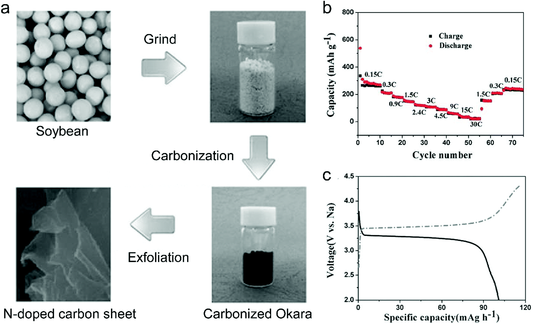 | ||
| Fig. 17 (a) Schematic representation of the preparation of N-doped carbon sheets. (b) The capacity retention of the N-doped carbon sheets at current densities from 56.25 mA g−1 to 11.25 A g−1. (c) Charge and discharge curves of the carbon sheets//Na3V2(PO4)3 sodium ion batteries at 562 mA g−1. Reproduced from ref. 316 with permission from Wiley-VCH. | ||
Synthetic carbon-rich compounds are another category of precursors for synthesizing hard carbon materials.324 Most of these materials are polymers, like polyvinyl chloride,325 polyaniline,326–328 polyamic acid,329 and PAN.330,331 Wang et al.329 used an electrospinning technique to fabricate a thin film composed of polyamic acid nanofibers. The carbon film, obtained by direct carbonization at a temperature of 650 °C for 3 hours, was capable of delivering a reversible specific capacity of 377 mA h g−1. Tarascon's group330 fabricated a series of hard carbon materials by the pyrolysis of electrospun PAN nanofibers at temperatures ranging from 650 to 2800 °C. They revealed the Na-ion storage ability of the obtained hard carbon strongly depending on the different features induced by the pyrolysis temperature. With a low pyrolysis temperature (<1000 °C), the derived carbon materials contained numerous heteroatoms (including O, N). Heteroatoms were gradually removed when the pyrolysis temperature was above 1000 °C; meanwhile the increase of the ordered structure and mesoporous volume was demonstrated. Importantly, when the pyrolysis temperature reached more than 2000 °C, high-density graphite domains were observed, accompanied by the formation of rich pores surrounded by graphite layers. Meanwhile, the voltage curve of the derived carbon showed a clear single plateau at around 0.1 V, corresponding to a reversible capacity of 200 mA h g−1. The authors verified that such a plateau was associated with the filling of nanopores by Na+. Recently, Chen et al.331 used a similar electro-spinning method to achieve PAN/Zn(Ac)2/Co(Ac)2 nanofiber networks. The obtained fiber was subsequently immersed in 2-methylimidazole solution, allowing the growth of Zn–Co bimetallic zeolitic imidazolate frameworks onto the nanofibers. Afterwards, the nanofibers were carbonized at 700 °C for 20 hours and washed with acid, affording the flexible free-standing film made of N-doped porous carbon nanofibers (Fig. 18a). As depicted in Fig. 18b, the obtained carbon nanofibers have a rough surface and a characteristic tubular structure with a diameter of 170–190 nm. Such a morphology is beneficial for the access of the carbon surface to the electrolyte and for the efficient transportation of electrolyte ions. The high-resolution TEM image (Fig. 18c) shows a large interlayer spacing of 0.38–0.44 nm, significantly outclassing the interlayer spacing of typical graphite. Moreover, the derived carbon nanofibers showed a high specific surface area of 438 m2 g−1 and rich micro-pores (diameter of 0.6 and 1.5 nm) and meso-pores (diameter of 3.5 nm) (Fig. 18d). The first-cycle discharge capacity and charge capacity of the obtained carbon nanofibers were measured to be 346 and 735 mA h g−1 at 120 mA g−1, respectively, corresponding to a first-cycle CE of 47.1% (Fig. 18e). The excellent rate capability and cycling stability of the carbon nanofibers were further evidenced by the high reversible capacity of 128 mA h g−1 at a large current density of 7 A g−1 and no clear capacity decay after cycling at 4.5 A g−1 for 10000 cycles (Fig. 18f). Apart from polymers, other carbon-rich compounds were used to synthesize disordered carbon.332–334 For instance, Ji's group333 first synthesized oligomer chain-based carbon quantum dots from acetone through aldol and polymerization reaction. After carbonization at 800 °C, the quantum dots were self-assembled into 3D porous carbon frameworks with an interlayer spacing of 0.42 nm. The maximum reversible capacity of these 3D porous carbon frameworks reached 255.5 mA h g−1. By directly carbonizing sodium citrate at 700 °C, Yan with his colleagues332 reported a kind of 3D carbon framework with a high reversible specific capacity of 330 mA h g−1 at 50 mA g−1.
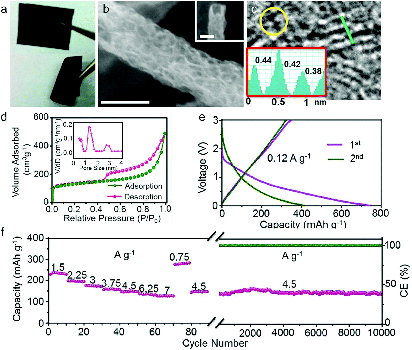 | ||
| Fig. 18 (a) Digital photograph, (b) SEM image (scale bars: 100 nm), (c) high-resolution TEM image, (d) nitrogen adsorption–desorption isotherms and pore-size distributions, (e) charge–discharge voltage profiles at 0.12 A g−1, and (f) cycling performance at 4.5 A g−1 of the polyacrylonitrile/Zn(Ac)2/Co(Ac)2 nanofiber derived porous carbon nanofiber networks. Reproduced from ref. 331 with permission from Elsevier. | ||
(3) Heteroatom-doped carbon anodes. Heteroatom doping (including N-doping,158,159,305,314,322,326,335–338 P-doping,115,336,339 S-doping,159,314,339,340 B-doping338,339) is also viewed as an efficient way to boost the Na-ion storage capacity. Two functions of heteroatoms were concluded: one is to dilate the carbon layer and promote Na+ intercalation/deintercalation into graphite, and the other is to provide additional Na+ storage sites. Like heteroatom-doped carbon materials for LIBs, heteroatom-doped carbon materials for NIBs were realized by either using heteroatom-containing carbon precursors or using additional heteroatom donors. N-Doped carbon has been the earliest and also the most studied heteroatom-doped carbon. As an example, Zhao with his colleagues322 obtained a kind of N-doped hard carbon nanoshell from an artemia cyst shell precursor. The precursor was mixed with KOH and Ni(AC)2 and carbonized at 850 °C. During the pyrolysis, Ni2+ first chelated with chitosan in artemia cyst shells, and then catalyzed the graphitization of carbon. Meanwhile, KOH activated the carbon materials by producing a great deal of micropores. The obtained N-doped carbon materials exhibited a high reversible Na+-storage capacity of 325 mA h g−1 at 100 mA g−1. After 200 cycles, a specific capacity of 174 mA h g−1 was retained. Xu et al.305 annealed 3D graphite oxide under a mixture of NH3 and Ar at 800 °C to synthesize a 3D N-doped graphene material (denoted as N-GF). XPS revealed a N-doping level of 5.9 at% for the obtained 3D N-doped graphene. 3D graphene without N doping was also synthesized for comparison (denoted as rGF). Impressively, the initial reversible capacity of N-GF (1057.1 mA h g−1) at 100 mA g−1 was substantially higher than that of rGF (836.2 mA h g−1). At an ultra large current density of 5 A g−1, the specific capacity of N-GF was still maintained at 137.7 mA h g−1, whilst rGF only showed a low specific capacity of 10.5 mA h g−1.
Apart from the N dopant, other heteroatoms also have a significant influence on the structure of carbon materials. Recently, with the assistance of experimental studies and computational calculations, Li et al.339 evaluated the effect of P doping, S doping and N-doping on the Na-storage behavior. Different kinds of heteroatom-doped carbon materials were synthesized by pyrolyzing the mixture of carbon precursor (sucrose/graphite oxide, 80:1) with different oxo acids (H3PO4, H2SO4 or H3BO3). The XRD results (Fig. 19a) identified that P-doped (0.395 nm) and S-doped (0.383 nm) carbon had enlarged average interlayer spacings, while B-doped carbon (0.378 nm) had almost the same interlayer spacing as non-doped carbon materials (0.377 nm). Fig. 19b further compares the first-cycle charge/discharge curves at 20 mA g−1. As revealed, the Na+-storage capacity at low-voltage plateau is greatly improved for P-doped (240 mA h g−1) and S-doped (213 mA h g−1) carbon compared with non-doped carbon (175 mA h g−1), which can be assigned to the promoted Na+ intercalation into the carbon interlayer. Meanwhile, the Na+-storage capacity at the sloping voltage region is enhanced for P-doped (245 mA h g−1) and B-doped (304 mA h g−1) carbon compared to non-doped carbon (178 mA h g−1), which was explained by the increased defect concentration of carbon materials. This study suggests that the superior hard carbon materials for SIBs should have both high reversibly Na-binding defects and expanded carbon interlayer spacing. Moreover, Zhou's group159 employed a sol–gel approach to first get a mixed precursor containing urea and citric acid. Afterwards, the precursor was annealed under Ar/H2S at 650 °C, obtaining N,S-codoped carbon nanosheets. Interestingly, compared with only N-doped carbon nanosheets (0.350 nm), N,S-codoped carbon nanosheets show obviously expanded interlayer spacings (0.377 nm). The specific capacity of N,S-codoped carbon nanosheets also showed great enhancement compared with N-doped carbon nanosheets, for example, 419 mA h g−1vs. 237.2 mA h g−1 for the first-cycle reversible capacity at 50 mA g−1. Wang et al.338 reported a kind of B,N-codoped carbon nanofiber by annealing the mixture of bacterial cellulose with NH4HB4O7·H2O under an Ar atmosphere. The obtained B,N-codoped carbon nanofibers exhibited an ultrahigh reversible capacity of 691 mA h g−1 at 100 mA g−1, but a low CE of 36.6%. A good cycling stability was also verified by a low capacity decay of 0.57% per cycle after 120 cycles at 100 mA g−1.
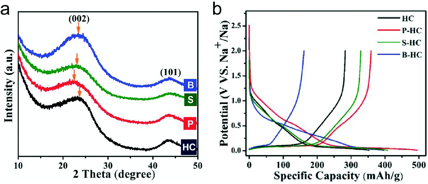 | ||
| Fig. 19 (a) XRD patterns of doped and undoped carbons. After P- and S-doping, the (002) peak shifts to a lower angle, which indicates a larger d-spacing. However, B-doping barely shifts the peak. (b) Galvanostatic sodiation/desodiation potential profiles of hard carbon and doped hard carbons at a current rate of 20 mA g−1. Reproduced from ref. 339 with permission from Wiley-VCH. | ||
To correlate the structural parameters of carbon materials with their Na+-storage performance, Table 4 compares the recently reported carbon materials for Na+ storage.
| Type of carbon material | Specific surface area | Interlayer distance | Specific capacity | First-cycle CE | Cycling stability | Ref. |
|---|---|---|---|---|---|---|
| rGO | 330.9 m2 g−1 | — | 174.3 mA h g−1 at 40 mA g−1 | 20% | 45% at 40 mA g−1 over 1000 cycles | 151 |
| 95.6 mA h g−1 at 1 A g−1 | ||||||
| rGO paper | — | 0.365 nm | 115 mA h g−1 at 100 mA g−1 | 28% | 87% at 100 mA g−1 over 1000 cycles | 300 |
| 52 mA h g−1 at 2.4 A g−1 | ||||||
| Holey graphene | 750 m2 g−1 | 0.375 nm | 220 mA h g−1 at 30 mA g−1 | 22% | 72% at 100 mA g−1 over 500 cycles | 301 |
| 85 mA h g−1 at 10 A g−1 | ||||||
| Hydrogenated graphene | — | — | 430 mA h g−1 at 100 mA g−1 | 8.6% | — | 302 |
| 240 mA h g−1 at 5 A g−1 | ||||||
| rGO | 0.365 nm | 428 mA h g−1 at 25 mA g−1 | 18.5% | 81% at 125 mA g−1 over 750 cycles | 303 | |
| 162 mA h g−1 at 500 mA g−1 | ||||||
| Graphene paper | 47.4 m2 g−1 | — | 183 mA h g−1 at 100 mA g−1 | 32.7% | 74% at 1 A g−1 over 500 cycles | 304 |
| 61 mA h g−1 at 8 A g−1 | ||||||
| Graphene | 523 m2 g−1 | 0.374 nm | 225 mA h g−1 at 50 mA g−1 | 46.8% | — | 149 |
| 51 mA h g−1 at 1 A g−1 | ||||||
| 3D N-doped graphene | 357 m2 g−1 | 0.342 nm | 1057 mA h g−1 at 100 mA g−1 | 42.6% | 70% at 500 mA g−1 over 150 cycles | 305 |
| 137.7 mA h g−1 at 5 A g−1 | ||||||
| Peat moss derived N-doped carbon | 196 m2 g−1 | 0.388 nm | 203 mA h g−1 at 500 mA g−1 | 57.5% | 88% at 100 mA g−1 over 200 cycles | 306 |
| 66 mA h g−1 at 5 A g−1 | ||||||
| Banana peel derived N-doped carbon | 130.8 m2 g−1 | 0.392 nm | 355 mA h g−1 at 50 mA g−1 | 70% | 93% at 500 mA g−1 over 600 cycles | 307 |
| 80 mA h g−1 at 5 A g−1 | ||||||
| Peanut shell derived N-doped carbon | 706.1 m2 g−1 | — | 320 mA h g−1 at 250 mA g−1 | 30% | 77% at 250 mA g−1 over 400 cycles | 308 |
| 140 mA h g−1 at 1 A g−1 | ||||||
| Coconut oil derived S-doped carbon | 56 m2 g−1 | — | 198 mA h g−1 at 100 mA g−1 | 49% | 85% at 100 mA g−1 over 200 cycles | 309 |
| 78 mA h g−1 at 1 A g−1 | ||||||
| Cotton derived hard carbon | 38 m2 g−1 | 0.410 nm | 315 mA h g−1 at 30 mA g−1 | 83% | 97% at 30 mA g−1 over 100 cycles | 310 |
| 180 mA h g−1 at 300 mA g−1 | ||||||
| Garlic peel derived N-doped carbon | 1710 m2 g−1 | 0.379 nm | 270 mA h g−1 at 250 mA g−1 | 41% | 88% at 100 mA g−1 over 100 cycles | 311 |
| 37 mA h g−1 at 4 A g−1 | ||||||
| Wood derived carbon | — | — | 270 mA h g−1 at 10 mA g−1 | 70% | — | 312 |
| Apple-biowaste derived carbon | 196.3 m2 g−1 | 0.385 nm | 245 mA h g−1 at 4 mA g−1 | 61% | 113% at 1 A g−1 over 1000 cycles | 313 |
| 86 mA h g−1 at 2 A g−1 | ||||||
| Cellulose/polyaniline derived N,S-doped carbon | — | 0.406 nm | 280 mA h g−1 at 30 mA g−1 | 23% | 100% at 500 mA g−1 over 3400 cycles | 314 |
| 131 mA h g−1 at 5 A g−1 | ||||||
| Cellulose derived carbon | 117 m2 g−1 | 0.377 nm | 280 mA h g−1 at 20 mA g−1 | 54% | 83% at 200 mA g−1 over 170 cycles | 315 |
| Okara derived N-doped carbon | — | 0.390 nm | 302 mA h g−1 at 56 mA g−1 | — | 65% at 1.7 A g−1 over 2000 cycles | 316 |
| 32 mA h g−1 at 11.25 A g−1 | ||||||
| Leaf-derived lamellar carbon | — | — | 254 mA h g−1 at 20 mA g−1 | 60% | 99% at 20 mA g−1 over 100 cycles | 317 |
| 103 mA h g−1 at 200 mA g−1 | ||||||
| Argan shell derived carbon | 23 m2 g−1 | 0.393 nm | 333 mA h g−1 at 25 mA g−1 | 79% | 96% at 25 mA g−1 over 100 cycles | 318 |
| Pistachio shell derived carbon | 760.9 m2 g−1 | 0.370 nm | 225 mA h g−1 at 10 mA g−1 | 71% | 86.3% at 40 mA g−1 over 50 cycles | 319 |
| 90 mA h g−1 at 200 mA g−1 | ||||||
| Shrimp skin derived N-doped carbon | 531 m2 g−1 | 0.366 nm | 276 mA h g−1 at 100 mA g−1 | 32% | 71% at 50 mA g−1 over 300 cycles | 320 |
| 160 mA h g−1 at 1 A g−1 | ||||||
| Mangosteen shell derived carbon | 81.5 m2 g−1 | 0.371 nm | 275 mA h g−1 at 20 mA g−1 | 74% | 98% at 20 mA g−1 over 100 cycles | 321 |
| 98 mA h g−1 at 200 mA g−1 | ||||||
| Artemia cyst shell derived N-doped carbon | 1490 m2 g−1 | 0.347–0.400 nm | 1253 mA h g−1 at 100 mA g−1 | 53.4% | 54% at 100 mA g−1 over 200 cycles | 322 |
| 175 mA h g−1 at 20 A g−1 | ||||||
| Macadamia shell derived carbon | 32.4 m2 g−1 | 0.390 nm | 297 mA h g−1 at 30 mA g−1 | 91.4% | 30 mA g−1 for 850 h | 323 |
| 260 mA h g−1 at 300 A g−1 | ||||||
| Polyvinyl chloride nanofiber derived carbon | — | 0.351 nm | 389 mA h g−1 at 12 mA g−1 | 69.9% | 84% at 12 mA g−1 over 150 cycles | 325 |
| 147 mA h g−1 at 240 mA g−1 | ||||||
| N-Doped carbon/graphene | 94.1 m2 g−1 | 0.360 nm | 336 mA h g−1 at 30 mA g−1 | 52% | 89% at 50 mA g−1 over 200 cycles | 326 |
| 94 mA h g−1 at 5 A g−1 | ||||||
| Polyaniline derived N-doped carbon | 23.5 m2 g−1 | 0.366 nm | 270 mA h g−1 at 50 mA g−1 | 51.6% | 77% at 50 mA g−1 over 500 cycles | 327 |
| 45 mA h g−1 at 2.5 A g−1 | ||||||
| N-Doped carbon nanofiber film | 564.4 m2 g−1 | — | 564 mA h g−1 at 100 mA g−1 | 35% | 99% at 5 A g−1 over 7000 cycles | 329 |
| 154 mA h g−1 at 15 A g−1 | ||||||
| Polyaniline derived carbon nanofibers | 21 m2 g−1 | — | 200 mA h g−1 at 35 mA g−1 | — | 87% at 35 mA g−1 over 50 cycles | 330 |
| PAN/Co(Ac)2/ZIF derived N-doped carbon | 438 m2 g−1 | 0.380–0.440 nm | 346 mA h g−1 at 120 mA g−1 | 47% | 95% at 4.5 A g−1 over 10000 cycles |
331 |
| 128 mA h g−1 at 7 A g−1 | ||||||
| Sodium citrate derived 3D carbon | <370 m2 g−1 | 0.340–0.510 nm | 440 mA h g−1 at 50 mA g−1 | 32.2% | 100% at 10 A g−1 over 10000 cycles |
332 |
| 100 mA h g−1 at 20 A g−1 | ||||||
| 3D porous carbon | 467 m2 g−1 | 0.420 nm | 255 mA h g−1 at 500 mA g−1 | 34.7% | 96% at 5 A g−1 over 10000 cycles |
333 |
| 100 mA h g−1 at 20 A g−1 | ||||||
| C24H8O6 derived soft carbon | 20.2 m2 g−1 | 0.356 nm | 200 mA h g−1 at 20 mA g−1 | 67.6% | 89% at 1 A g−1 over 240 cycles | 334 |
| 114 mA h g−1 at 1 A g−1 | ||||||
| Hard carbon | 8.5 m2 g−1 | 0.377 nm | 283 mA h g−1 at 20 mA g−1 | 80.1% | — | 339 |
| P-Doped hard carbon | 7.3 m2 g−1 | 0.395 nm | 359 mA h g−1 at 20 mA g−1 | 74.0% | 91% at 20 mA g−1 over 200 cycles | |
| B-Doped hard carbon | 8.0 m2 g−1 | 0.378 nm | 147 mA h g−1 at 20 mA g−1 | 36.4% | 98% at 20 mA g−1 over 200 cycles | |
| S-Doped hard carbon | 5.2 m2 g−1 | 0.383 nm | 328 mA h g−1 at 20 mA g−1 | 80.4% | 87% at 20 mA g−1 over 200 cycles | |
| N-doped carbon | 945 m2 g−1 | 0.367 nm | 437 mA h g−1 at 100 mA g−1 | 52% | 79% at 1.6 A g−1 over 5000 cycles | 335 |
| 96 mA h g−1 at 6.4 A g−1 | ||||||
| N,P-Doped carbon | 432 m2 g−1 | — | 305 mA h g−1 at 100 mA g−1 | 47% | 80% at 100 mA g−1 over 50 cycles | 336 |
| 136 mA h g−1 at 5 A g−1 | ||||||
| B,N-Doped carbon nanofibers | 1585 m2 g−1 | 0.440 nm | 691 mA h g−1 at 100 mA g−1 | 36.6% | 85% at 10 A g−1 over 1000 cycles | 338 |
| 314 mA h g−1 at 10 A g−1 | ||||||
| N-Doped carbon nanosheets | 214 m2 g−1 | 0.361 nm | 278 mA h g−1 at 100 mA g−1 | 54.2% | 114% at 10 A g−1 over 10000 cycles |
337 |
| 159 mA h g−1 at 10 A g−1 | ||||||
| N,S-Doped carbon | 379.4 m2 g−1 | 0.378 nm | 350 mA h g−1 at 50 mA g−1 | 44% | 96% at 1 A g−1 over 1000 cycles | 159 |
| 110 mA h g−1 at 10 A g−1 | ||||||
| POx-Doped carbon | — | 0.386 nm | 359 mA h g−1 at 20 mA g−1 | 73% | 92% at 200 mA g−1 over 150 cycles | 115 |
| S-Doped carbon | 139.7 m2 g−1 | 0.386 nm | 482 mA h g−1 at 100 mA g−1 | 73.6% | 94.2% at 500 mA g−1 over 700 cycles | 340 |
| 119 mA h g−1 at 5 A g−1 |
(1) Ordered carbon anodes. The research on carbon anodes for KIBs has been stimulated starting from 2015, when Ji's group125 and Hu's group160 reported the reversible K+ intercalation/de-intercalation behavior of graphite, respectively (as discussed early in Section 3.1.3). However, in these two early studied cases, K+ intercalation into graphite suffers from low initial CE, low rate capability, as well as fast capacity decay. To alleviate these issues faced by K+ intercalated graphite, early research tried to optimize the employed electrolytes and binders. For example, Komaba et al.341 demonstrated that the binders sodium polyacrylate and sodium carboxymethylcellulose were beneficial to improve the first-cycle CE. In an electrolyte of 1 M KFSI in EC/DEC, graphite with sodium polyacrylate (89%) and sodium carboxymethylcellulose binders (79%) showed superior first-cycle CEs compared to graphite with the traditional poly(vinylidene fluoride) binder (only 59%). The improved CE was explained by the pre-formation of the SEI and the suppressed defluorination of poly(vinylidene fluoride). Wang with his colleagues342 studied the K+-storage performance of graphite in different electrolytes, including 1 M KPF6 dissolved in EC/DMC, EC/DEC, and EC/PC. Both electrolytes with EC/DEC and EC/PC solvents enabled a high first-cycle CE and stable cycling performance after 200 cycles for the graphite electrode. By contrast, graphite with the EC/DMC based electrolyte could not form a stable SEI film, thus resulting in a fast capacity decay after 70 cycles. Moreover, Cohn et al.343 reported K+ intercalation into graphite with diglyme and monoglyme based electrolytes. Without the desolvation process, the co-intercalation of K+ and solvent into graphite allowed for a specific capacity of 100 mA h g−1 at 200 mA g−1, a fast rate capability with a capacity retention of 80% at 10 A g−1, and stable cycling performance with 5% capacity decay after 2000 cycles at 2 A g−1A g−1.
Recently, the K+-storage behavior was also studied for other ordered nanoscale carbon materials, like nanosized graphitic carbon,345 graphene,161,346 and CNTs.344,347,348 For instance, Song et al.345 annealed Ketjen carbon black at 2800 °C and obtained graphitic carbon nanocages with an average diameter of about 50 nm and a thin shell of 5 nm. Such a unique structure was capable of accommodating strain relaxation during K+ intercalation/de-intercalation, reducing the ion diffusion length and accelerating electron transport. The obtained graphitic carbon nanocages delivered a reversible specific capacity of 221.5 mA h g−1 at 28 mA g−1. Remarkably, the specific capacity maintained 79% of the capacity at 28 mA g−1 when the current was increased to 9.7 A g−1, suggesting the ultrahigh rate capability. By using Ni foam as a catalyst and CH3CN as a precursor, Share and co-authors161 employed the CVD method to grow N-doped graphene materials. The obtained N-doped graphene showed a high specific capacity of 350 mA h g−1, significantly outperforming the theoretical capacity of graphite (278 mA h g−1). The cycling tests at 100 mA g−1 revealed a fair electrochemical stability of the N-doped graphene anode with an initial capacity of 270 mA h g−1 and a final capacity of 210 mA h g−1 after 100 charge/discharge cycles. In addition, Wang et al.344 reported a kind of hyperporous sponge made of highly tangled CNTs, which were synthesized by a CVD approach with ferrocene as the catalyst and 1,2-dichlorobenzene as the carbon precursor. The CNTs were featured by dense-stacked inner walls and loose-stacked outer walls (Fig. 20a). The interlayer spacing of inner walls was revealed to be 0.344 nm, close to that of graphite, while the outer walls appeared to be disordered with an average interlayer spacing of 0.427 nm (Fig. 20b). Fig. 20c shows the initial three CV cycles of the sponge as the anode for K+ storage. During the first cathodic scan, there are three cathodic peaks at 0.01, 0.2, and 0.5 V vs. K+/K. Afterwards, the peak at 0.5 V vs. K+/K disappeared due to the formation of an irreversible SEI film, and two anodic peaks at 0.4 and 0.6 V vs. K+/K appeared. After activation for 50 cycles, the obtained CNT sponge delivered a reversible specific capacity of 232 mA h g−1 at 100 mA g−1, and an outstanding stability with negligible capacity decay after 500 cycles (Fig. 20d). Ex situ TEM images provide important understanding of the superior K+-storage behavior of the obtained CNT sponge (Fig. 20e). The K+ intercalation mainly took place within the outer CNT walls, while the inner CNT walls functioned as a robust skeleton. During the repeat charge/discharge, the obtained CNT sponge presented reversible expansion/shrinkage.
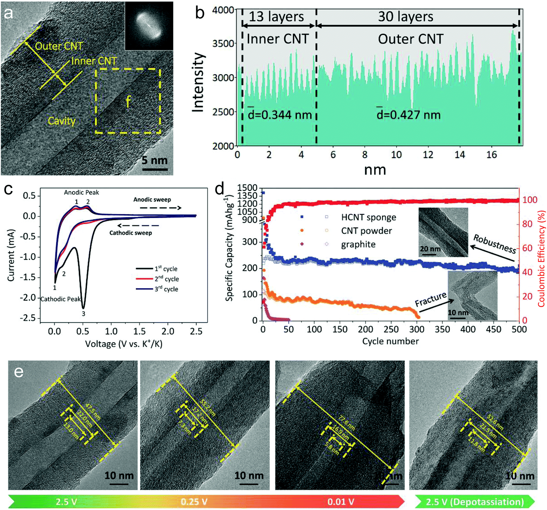 | ||
| Fig. 20 (a) TEM image of a CNT. (b) Line profile obtained from the wall of a CNT. (c) CV curves of CNT sponge at 0.3 mV s−1. (d) Cycling performance of CNT sponge, commercial CNT powder and graphite electrodes at a current density of 100 mA g−1. (e) Ex situ TEM images of the CNT structure at different potassiation and de-potassiation potential in the first cycle. Reproduced from ref. 344 with permission from Wiley-VCH. | ||
(2) Disordered carbon anodes. Research on disordered carbon for KIBs occupies the dominant research trend for carbon based KIB anodes, particularly in these five years. Biomass materials (e.g. chitin,350,351 bacterial cellulose,341,349 potato,352 pepper,353 walnut septum,354 and juice355) are one key category to synthesize disordered carbon materials for K+ storage, owing to their abundant, renewable and eco-friendly features. Through a simple pyrolysis process as well as washing and drying, the derived carbon can be produced on a large scale. For instance, Zhang's group351 developed an emulsion method to fabricate chitin microspheres by dissolving chitin in NaOH/urea aqueous solution. By directly carbonizing chitin microspheres under an Ar atmosphere, they further prepared N-doped carbon nanospheres and employed them as the anode for KIBs. It was demonstrated that the obtained carbon nanospheres delivered a high specific capacity of 250 mA h g−1 at 33.6 mA g−1, an excellent rate capability with a specific capacity of 154 mA h g−1 at 20.16 A g−1, as well as an ultralong stability of 4000 cycles. Recently, Li et al.349 also reported a kind of carbon aerogel derived from bacterial cellulose, which showed a remarkable K+-storage ability. Bacterial cellulose can be produced by the fermentation of Acetobacter xylinum, which is a cost-effective and upscalable process. In this study, bacterial cellulose hydrogel was first freeze-dried into aerogel, and then pyrolyzed at a temperature of 1000 °C under a N2 atmosphere (Fig. 21a). The lightweight carbon aerogel has a mass density of about 5.3 mg cm−3, which enables it to stand on a flower stably (Fig. 21b). It can bear a compression of up to 90% volume change and recover to the initial state without structural collapse, implying its robust elasticity. The SEM image (Fig. 21c) reveals that the carbon aerogel is featured with a porous 3D reticulated structure made of numerous tangled carbon nanofibers. The high-resolution TEM image (Fig. 21d) clearly shows numerous nanopores uniformly distributed on the surface of each nanofiber. With such a hierarchical porous structure, the obtained carbon aerogel shows a large specific surface area of 778 m2 g−1 with rich micropores accounting for 53% of the total surface area (Fig. 21e). The K+-storage ability of the carbon aerogel was assessed in a half cell with a voltage window of 0.01–2.80 V vs. K+/K. By collecting CV curves at various scan rates, the K+-storage behavior of the obtained carbon aerogel was determined to be a surface-driven dominant process (Fig. 21f). Even at a low scan rate of 0.2 mV s−1, the capacitive contribution to the whole K+ storage reached up to 51%. This surface-dominant K+ storage behavior enabled the carbon aerogel a fast rate capability. The specific capacity of the carbon aerogel was 240 mA h g−1 at 50 mA g−1; meanwhile the specific capacity was still maintained at 164 mA h g−1 at 1 A g−1 (Fig. 21g). Moreover, after 2000 charge/discharge cycles at 1 A g−1, the carbon aerogel still showed a specific capacity of 158 mA h g−1, indicating an average capacity decay rate of only 0.006% per cycle (Fig. 21h). Afterwards, the carbon aerogel could be stably operated at 2 A g−1 for another 1500 cycles, and subsequently at 5 A g−1 for another 1000 cycles. It should be pointed out that, although the high porosity and large specific surface area endowed a fast rate capability of the obtained carbon anodes for KIBs, they also led to the low first-cycle CE of the carbon anodes (less than 50%).
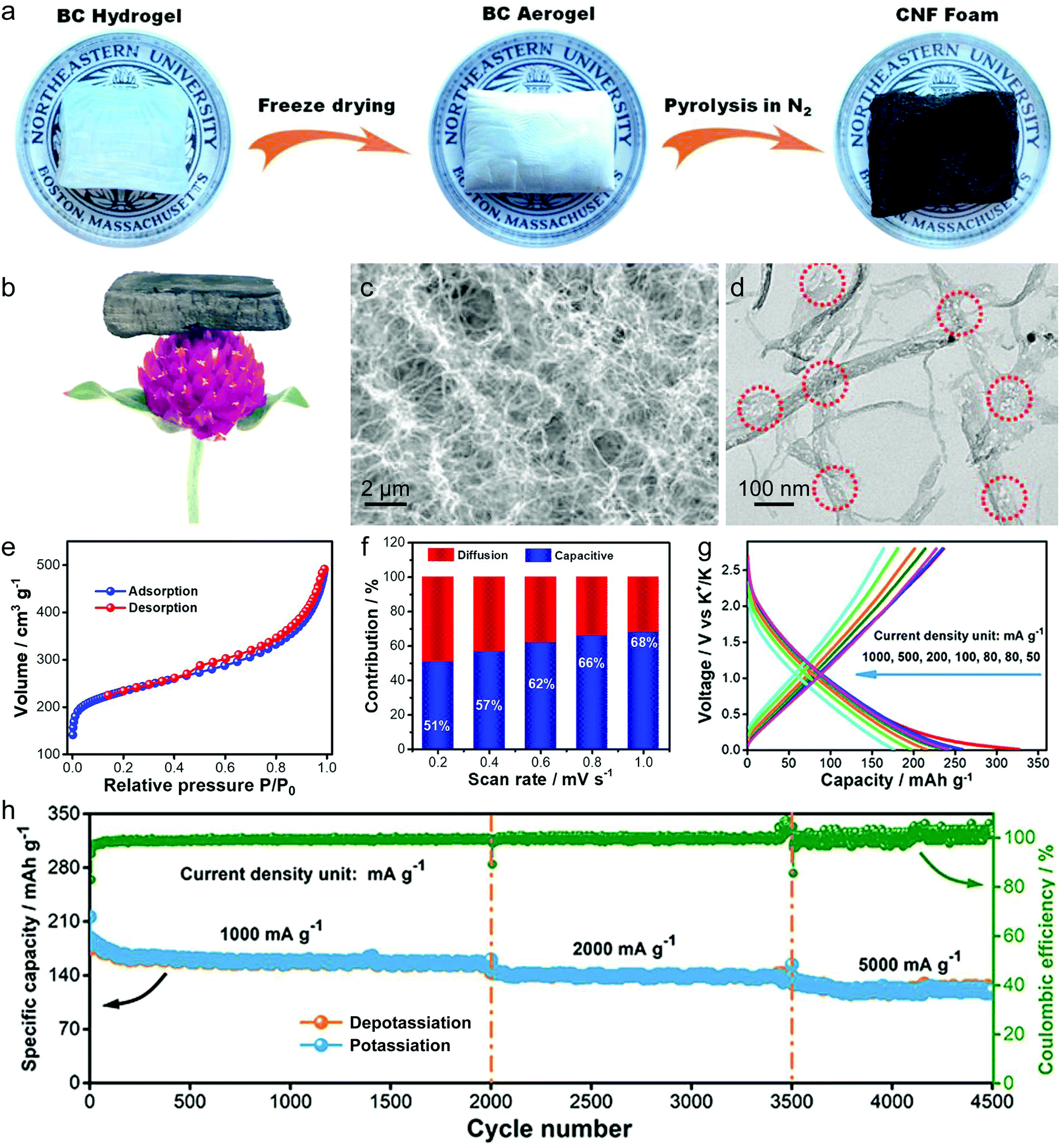 | ||
| Fig. 21 (a) Schematic diagram of preparation of the bacterial cellulose derived carbon aerogel. (b) Photograph of the carbon aerogel standing on a flower, indicating its foam-like property. (c) SEM image, (d) TEM image, and (e) nitrogen adsorption–desorption isotherm curve of the carbon aerogel. (f) Contribution ratios of capacitive and diffusion capacities of the carbon aerogel electrode at various scan rates. (g) Depotassiation–potassiation profiles at various current densities. (h) Long-term cycling performances. Reproduced from ref. 349 with permission from American Chemical Society. | ||
Synthetic carbon-rich compounds have also attracted widespread attention as carbon precursors for synthesizing K+-storage disordered carbon. So far, various polymers have been explored to fabricate porous hard carbon materials for K+ storage, including electrospun PAN,357,358 polymerization product of sucrose,359 melamine–formaldehyde resin,158,356 polyaniline,360 and sodium polyacrylate.361 For instance, Ji's group359 used a hydrothermal reaction of sucrose solution to get the polymerization microspheres of sucrose, which were further carbonized at 1100 °C for 5 hours under Ar gas. The obtained carbon microspheres were subjected to assessment of their Na+- and K+- storage ability. Interestingly, they showed a lower K+-storage capacity (262 mA h g−1) than Na+-storage capacity (322 mA h g−1) at a low current density of 28 mA g−1, but a better K+-storage rate capability (136 mA h g−1 at 1.4 A g−1) than Na+-storage rate capability (73 mA h g−1 at 1.4 A g−1). This result was explained by the larger diffusion coefficient of K+ in carbon microspheres compared to that of Na+. Bin et al.356 recently observed an interesting glass blowing effect of the melamine–formaldehyde resin during pyrolysis, which resulted in a hollow 3D carbon foam. They selected commercial melamine–formaldehyde resin sponge as the precursor, and annealed it at 1300 °C under a N2 atmosphere. As shown in Fig. 22a, the pyrolysis process includes two steps, one is scission of ether linkages at temperature below 365 °C which softens the resin structure, and the other is release of large amounts of gas at temperature above 365 °C, which inflated the skeleton. The important role of ether linkages was also verified by the control experiment, in which solid carbon foam was obtained by firstly annealing the sponge at 365 °C to remove the ether bridge, then cooling down, and finally annealing it again at 1300 °C. EIS results (Fig. 22b) revealed that hollow carbon foam showed the lowest charge-transfer impedance compared with solid carbon foam and carbon powder, which could be attributed to the shortened K+ diffusion distance of the hollow structure with thin walls. Remarkably, the obtained hollow carbon foam showed a high reversible capacity of 340 mA h g−1 at 28 mA g−1, greatly outperforming the solid carbon foam and powder carbon (Fig. 22c). Of note is that the first-cycle CE of the hollow carbon foam reached up to 72.1%. At a high current density of 558 mA g−1, the specific capacity of the hollow carbon foam was still maintained around 110 mA h g−1.
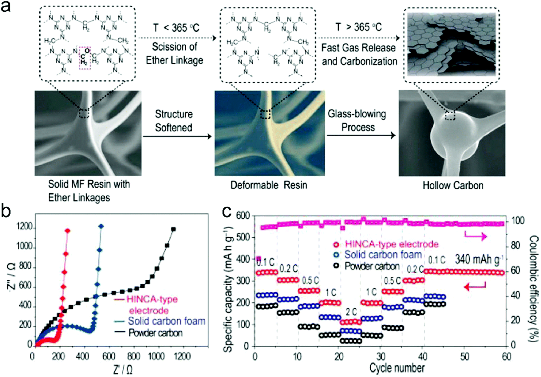 | ||
| Fig. 22 (a) Schematic illustration of the spontaneous formation of the hollow carbon structure. (b) EIS and (c) rate capability of the obtained hollow carbon foam, solid carbon foam and carbon powder. Reproduced from ref. 356 with permission from American Chemical Society. | ||
Metal–organic frameworks featured with ultra-large porosity and high crystallinity are also appropriate precursors for synthesizing nanoporous carbon materials.362–364 MOFs are composed of metal centers and organic ligands. The organic ligands provide sufficient carbon sources, while the metal content (e.g. Co) shows a good catalytic ability to promote the formation of graphitic carbon even at low temperatures. For example, Hu and co-authors362 directly annealed Co-containing zeolitic imidazolate frameworks (ZIF-67) at 600 °C, followed by washing with hard carbon to remove metal particles. They found that the size of the ZIF-67 precursor played a significant role in determining the morphology of the obtained carbon materials. When ZIF-67 was changed from microsize to nanosize, the derived carbon changed from particle morphology to interconnected 3D porous network morphology. At a low current density of 50 mA g−1, the reversible specific capacity of the 3D porous carbon networks reached 270 mA h g−1. Li et al.364 reported the synthesis of the core–shell Zn-containing ZIF @ Co-containing ZIF structure, and carbonized it at 900 °C under N2 for 5 hours. As the anode for KIBs, this carbon material also delivered an outstanding performance with a reversible specific capacity of 310 mA h g−1 at 100 mA g−1 after 200 cycles and good rate capability with a specific capacity of 120 mA h g−1 at 5 A g−1.
Besides, some other organic molecules, including citric acid/urea,365 sodium citrate/urea,366 resorcinol formaldehyde,367 2-amino terephthalic acid,368 sucrose,80 and melamine,369 were also directly selected as the precursors for the synthesis of disordered carbon. In most of the cases, templates were involved to promote the generation of pores with defined size, such as salts361,366,369 and SiO2.80,367 Li et al.366 ball-milled and annealed the mixture of sodium citrate and urea to synthesize a porous carbon anode for KIBs. During the calcination process, a large amount of Na2CO3 was formed which was wrapped by carbon nanosheets. After the removal of Na2CO3 templates, hierarchically porous carbon was obtained, showing favorable structural features, such as a large average interlayer distance (0.38 nm), a high specific surface area (340 m2 g−1), and multi-scale pores ranging from micro- to macro-pores. Importantly, the derived porous carbon showed a good K+-storage ability with a high reversible specific capacity of 384.2 mA h g−1 at 100 mA g−1 after 500 cycles and a high rate capability with a specific capacity of 185 mA h g−1 at 10 A g−1. Recently, Guo's group80 used a silica template (SBA-15) and a sucrose precursor to fabricate mesoporous carbon with ordered 1D 6.5 nm-width channels (Fig. 23a). Meanwhile, the obtained mesoporous carbon showed much larger interlayer spacing (0.52 nm) than crystalline graphite, allowing the storage of more K+ into carbon layers and the toleration of the volume change during potassiation/de-potassiation. The initial discharge/charge capacities of the mesoporous carbon at 50 mA g−1 were measured to be 483.2 and 307.4 mA h g−1, respectively, with a first-cycle CE of 63.6% (Fig. 23b). In the following 100 cycles, the capacity decay was much less, implying the reversible potassiation/de-potassiation. Ex situ XRD results (Fig. 23c) provided insightful understanding of the role of meso-channels in K+ storage. A peak at 1.1° was observed at the initial state, evidencing the ordered mesoporous arrangement. At the potassiation state, the peak shifted towards a higher angle, suggesting the narrowed meso-channels. After de-potassiation, the peak recovered to the angle between the initial state and the full potassiation state, implying a decrease in the diameter of meso-channels. Moreover, the cycling test demonstrated that the mesoporous carbon could maintain a reversible capacity of 146.5 mA h g−1 for 1000 cycles at 1 A g−1 (Fig. 23d).
 | ||
| Fig. 23 (a) TEM, (b) the 2nd, 3rd, 5th, 10th, 20th, 30th, 50th, 75th, and 100th potassiation/depotassiation profiles, (c) ex situ XRD patterns, and (d) long-term cycling stability and CE of the mesoporous carbon. Reproduced from ref. 80 with permission from Wiley-VCH. | ||
(3) Heteroatom-doped carbon anodes. As for Li+-storage and Na+-storage disordered carbon materials, introduction of heteroatoms is also pursued to improve the K+-storage ability of disordered carbon materials. The most general approach to realize heteroatom doping is selecting heteroatom-containing precursors (biomass or synthetic carbon rich compounds). The most widely studied case is N doping.158,358,360,363,365,368–370 Recently, Chang with his colleagues365 conducted DFT calculations to simulate the adsorption of K+ on different kinds of N-doping modes. The results showed that pyridinic N possessed the strongest K+ adsorption ability with an adsorption energy of −3.71 eV, whilst pyrrolic N and quaternary N had a K+ adsorption energy of −3.48 and −0.74 eV, respectively. This study inspires the design and synthesis of carbon materials with rich pyrrolic and pyridinic N for K+ storage. Lei and co-authors360 assessed the influence of the annealing temperature on N doping in polypyrrole nanofiber derived carbon. The derived carbon materials at 650, 950, and 1100 °C (denoted as NCNF-650, NCNF-950, and NCNF-1100) showed a similar hollow structure with an inner diameter of 30–40 nm and a wall thickness of 20 nm (Fig. 24a). As the annealing temperature increased, one could observe the diminishment of pyrrolic and pyridinic N, and the generation of quaternary N (Fig. 24b). Remarkably, NCNF-650 (368 mA h g−1) presented much higher initial capacity than NCNF-950 (297 mA h g−1) and NCNF-1100 (281 mA h g−1), which agrees well with the previous conclusion that pyrrolic and pyridinic N contribute to K+ storage (Fig. 24c). Moreover, the study demonstrated that the K+ storage of NCNF-650 showed higher surface-dominated contribution than that of NCNF-950 and NCNF-1100 (Fig. 24d). This fact can be explained by the rich surface/edge defects in NCNF-650 induced by the N dopants, which benefited the high-kinetics K+ storage. To demonstrate the possibility of the NCNF-650 anode for KIBs, a full cell was assembled by coupling with the Russian blue cathode. The cell tested in the voltage window of 2.0–4.2 V delivered a high specific capacity of 197 mA h g−1 (based on anode mass, Fig. 24e).
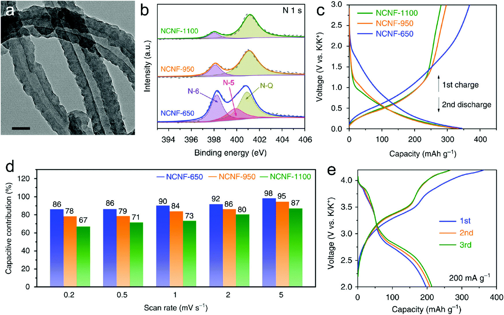 | ||
| Fig. 24 (a) TEM of NCNF-650. (b) N 1s core level XPS high-resolution spectra, (c) first charge and second discharge profiles, and (d) contribution of the surface process at different scan rates of NCNF-650, NCNF-950, and NCNF-1100. (e) Galvanostatic charge/discharge profiles of the NCNF-650//Prussian blue full cell. Reproduced from ref. 360 with permission from Springer Nature. | ||
Aside from N doping, S doping was also explored by recent research by selecting sulfur-containing precursors.203,346,371 For instance, Chen et al.203 synthesized polymer microspheres by thermal curing the mixture of epoxy monomers and thiol hardeners in a liquid crystal solvent. Afterwards, S-doped carbon microspheres were derived by carbonizing the microspheres, which exhibited a high K+-storage capacity of 226.6 mA h g−1 at 50 mA g−1. Liu et al.371 reported the synthesis of S,N-codoped hard carbon by annealing the mixture of polyacrylonitrile and sulfur. It showed a high reversible specific capacity of 293.8 mA h g−1 at 100 mA g−1. In both studies, the role of S dopants was assigned to create defects in the carbon plane and provide additional active sites for K+ adsorption.
Table 5 lists the structural properties and K+-storage performance of recently reported carbon materials.
| Type of carbon material | Specific surface area | Interlayer distance | Specific capacity | First-cycle CE | Cycling stability | Ref. |
|---|---|---|---|---|---|---|
| CNT sponge | 93 m2 g−1 | 0.344–0.427 nm | 1414 mA h g−1 at 100 mA g−1 | 15% | 90% at 100 mA g−1 over 500 cycles | 344 |
| 162 mA h g−1 at 1.6 A g−1 | ||||||
| Graphitic carbon nanocages | 102.7 m2 g−1 | 0.354 nm | 221.5 mA h g−1 at 27.9 mA g−1 | 40% | 95% at 56 mA g−1 over 100 cycles | 345 |
| 175 mA h g−1 at 9.8 A g−1 | ||||||
| N-Doped graphene | — | — | 350 mA h g−1 at 50 mA g−1 | 80% | 78% at 100 mA g−1 over 100 cycles | 161 |
| S-Doped rGO | 7.6 m2 g−1 | — | 435 mA h g−1 at 500 mA g−1 | 62% | 76% at 1 A g−1 over 500 cycles | 346 |
| 224 mA h g−1 at 1 A g−1 | ||||||
| N-Doped CNTs | — | 0.337–0.360 nm | 324 mA h g−1 at 10 mA g−1 | 14.2% | 76% at 20 mA g−1 over 100 cycles | 347 |
| 75 mA h g−1 at 1 A g−1 | ||||||
| CNT-modified graphitic carbon | 57.2 m2 g−1 | 0.342–0.391 nm | 229 mA h g−1 at 100 mA g−1 | 24% | 98% at 100 mA g−1 over 800 cycles | 348 |
| 180 mA h g−1 at 10 A g−1 | ||||||
| Bacterial cellulose derived carbon | 778.8 m2 g−1 | 0.370–0.390 nm | 240 mA h g−1 at 50 mA g−1 | — | 88% at 10 A g−1 over 2000 cycles | 349 |
| 164 mA h g−1 at 1 A g−1 | ||||||
| N-Doped carbon | 563 m2 g−1 | — | 250 mA h g−1 at 34 mA g−1 | — | 106% at 500 mA g−1 over 4000 cycles | 351 |
| 156 mA h g−1 at 5 A g−1 | ||||||
| Hard carbon | 77 m2 g−1 | 0.382 nm | 290 mA h g−1 at 25 mA g−1 | 81% | 98% at 25 mA g−1 over 50 cycles | 341 |
| 156 mA h g−1 at 5 A g−1 | ||||||
| Potato derived carbon | 532 m2 g−1 | — | 248 mA h g−1 at 100 mA g−1 | 43% | 100% at 500 mA g−1 over 400 cycles | 352 |
| 152 mA h g−1 at 1 A g−1 | ||||||
| Pepper derived carbon | 18.3 m2 g−1 | 0.386 nm | 284 mA h g−1 at 28 mA g−1 | 58% | 71% at 140 mA g−1 over 300 cycles | 353 |
| 167 mA h g−1 at 279 mA g−1 | ||||||
| Walnut septum derived N-doped carbon | 99.6 m2 g−1 | 0.376 nm | 305.7 mA h g−1 at 50 mA g−1 | 55.1% | 78% at 1 A g−1 over 1000 cycles | 354 |
| 102.6 mA h g−1 at 2 A g−1 | ||||||
| Hollow multihole carbon bowls | 425.1 m2 g−1 | 0.399 nm | 377 mA h g−1 at 100 mA g−1 | 66% | 81% at 100 mA g−1 over 150 cycles | 355 |
| 182 mA h g−1 at 2 A g−1 | ||||||
| N-Doped carbon nanofibers | 153 m2 g−1 | 0.370 nm | 220 mA h g−1 at 28 mA g−1 | 70% | 79% at 279 mA g−1 over 1750 cycles | 357 |
| 110 mA h g−1 at 2.8 A g−1 | ||||||
| N-Doped hollow carbon | 355.6 m2 g−1 | 0.371 nm | 294 mA h g−1 at 100 mA g−1 | 15% | 96% at 1 A g−1 over 1600 cycles | 358 |
| 205 mA h g−1 at 2 A g−1 | ||||||
| Carbon microspheres | 65 m2 g−1 | 0.400 nm | 262 mA h g−1 at 28 mA g−1 | 87% | 83% at 28 mA g−1 over 100 cycles | 359 |
| 130 mA h g−1 at 1.4 A g−1 | ||||||
| Hollow carbon architecture | 171 m2 g−1 | 0.356 nm | 340 mA h g−1 at 28 mA g−1 | 72.1% | 100% at 140 mA g−1 over 150 cycles | 356 |
| 110 mA h g−1 at 560 mA g−1 | ||||||
| N-Doped carbon nanofibers | 99 m2 g−1 | — | 248 mA h g−1 at 25 mA g−1 | 49% | 95% at 2 A g−1 over 4000 cycles | 360 |
| 101 mA h g−1 at 20 A g−1 | ||||||
| N-Doped porous carbon | 326 m2 g−1 | 0.361 nm | 349.4 mA h g−1 at 50 mA g−1 | 30.3% | 44% at 500 mA g−1 over 1000 cycles | 361 |
| 193.1 mA h g−1 at 500 mA g−1 | ||||||
| ZIF-67 derived N-doped CNTs | 126 m2 g−1 | 0.340 nm | 297.2 mA h g−1 at 50 mA g−1 | 24% | 78% at 2 A g−1 over 500 cycles | 363 |
| 131 mA h g−1 at 2 A g−1 | ||||||
| Zn-MOF/Co-MOF derived porous carbon | 430 m2 g−1 | 0.338 nm | 460 mA h g−1 at 100 mA g−1 | 15.7% | 65% at 100 mA g−1 over 200 cycles | 364 |
| 120 mA h g−1 at 5 A g−1 | ||||||
| Mesoporous carbon | 1089 m2 g−1 | 0.521 nm | 286.4 mA h g−1 at 50 mA g−1 | 63.6% | 70% at 1 A g−1 over 1000 cycles | 80 |
| 144.2 mA h g−1 at 1 A g−1 | ||||||
| N-Doped carbon nanosheets | 54 m2 g−1 | 0.340 nm | 440 mA h g−1 at 300 mA g−1 | — | 70% at 5 A g−1 over 3000 cycles | 365 |
| 170 mA h g−1 at 6 A g−1 | ||||||
| N-Doped porous carbon | 341 m2 g−1 | 0.383 nm | 420 mA h g−1 at 50 mA g−1 | 43.1% | 88% at 1 A g−1 over 1000 cycles | 366 |
| 185 mA h g−1 at 10 A g−1 | ||||||
| Hollow carbon nanospheres | 758 m2 g−1 | 0.379 nm | 370 mA h g−1 at 200 mA g−1 | 44.2% | 106% at 2 A g−1 over 5000 cycles | 367 |
| 137 mA h g−1 at 4 A g−1 | ||||||
| N,O-Doped hard carbon | 1030 m2 g−1 | 0.45 nm | 365 mA h g−1 at 25 mA g−1 | 25% | 72% at 1.05 A g−1 over 1100 cycles | 368 |
| 118 mA h g−1 at 3 A g−1 | ||||||
| Wrinkled carbon tubes | 290 m2 g−1 | — | 425 mA h g−1 at 50 mA g−1 | 45% | 92.8% at 3 A g−1 over 2000 cycles | 369 |
| 231 mA h g−1 at 2 A g−1 | ||||||
| N-Doped carbon nanosheets | 674 m2 g−1 | 0.369 nm | 361 mA h g−1 at 50 mA g−1 | 20% | 75.6% at 1 A g−1 over 1000 cycles | 370 |
| 168 mA h g−1 at 2 A g−1 | ||||||
| S,O-Doped porous carbon | 983.2 m2 g−1 | 0.393 nm | 225 mA h g−1 at 50 mA g−1 | 61.7 | 68% at 1 A g−1 over 2000 cycles | 203 |
| 158 mA h g−1 at 1 A g−1 | ||||||
| S,N-Doped hard carbon | 109.8 m2 g−1 | — | 293.8 mA h g−1 at 100 mA g−1 | 35% | 66% at 3 A g−1 over 1200 cycles | 371 |
| 175 mA h g−1 at 3 A g−1 | ||||||
| Pyridinic N-doped carbon | 443 m2 g−1 | 0.346 nm | 388 mA h g−1 at 500 mA g−1 | 57% | 61.5% at 500 mA g−1 over 3000 cycles | 158 |
| 178 mA h g−1 at 5 A g−1 |
4.2 Batteries based on the anion-intercalation carbon cathode
In this section, we introduce the recent progress and achievement in energy devices based on anion-intercalation graphitic carbon cathodes (including DIBs and AIBs). DIBs are a general concept with both cations and anions involved in the electrochemistry179 and they principally work in all electrolyte systems,173 while AIBs refer to energy devices based on two different Al-containing anions (AlCl4− and Al2Cl7−).170 We divide the discussion into separate parts according to the electrolyte systems. The electrochemistry, battery configuration, electrochemical performance, functions and remaining challenges are discussed in detail.(1) Intercalation-type anode//C batteries. Li+-based DIBs are the most investigated systems among all DIBs due to their high compatibility with the infrastructure of LIBs. Simply replacing Li-rich transition metal oxide cathodes of LIBs (C//LiMeOx) with graphitic carbon leads to dual-carbon or dual-graphite (C//C) batteries. The corresponding electrode reactions can be expressed as eqn (20) and (21). Exploiting graphitic carbon as both anode and cathode can largely reduce the cost of electrode materials and render C//C batteries with remarkable sustainability for scalable applications. The large potential gap between graphite cathode (4.2–4.7 V vs. Li+/Li) and graphite anode (<0.2 V vs. Li+/Li) affords a high working voltage of 4.0–4.5 V, which is superior to 3.7 V of the commercial LIBs. Even though proposed by McCullough30 in 1989, the concept of C//C batteries was not well demonstrated before and most research work mainly concentrated on Li//graphite half cells.130,372–374 Till 2007, Ishihara et al.228 screened various carbon materials and found a correlation of electrochemical performance and crystallinity of graphitic carbon. By using a graphitic carbon with high crystallinity and a carbonate electrolyte (1 M LiPF6 in EC/DMC), a rechargeable C//C battery with high capacity (90 mA h g−1) and high rate capability (0.4–4 mA cm−2) was, for the first time, demonstrated without describing cycling stability. The irreversible capacity in this system appeared to be quite high, leading to a relatively low CE (<64%). Read et al.206 explored a high-voltage electrolyte based on a fluorinated solvent and additive (1.7 M LiPF6 in FEC-EMC + 5 mM tris(hexafluoro-iso-propyl)phosphate), which can simultaneously enable Li+ and PF6− intercalation into graphitic carbon with the formation of a protective SEI and sufficient oxidative stability (5.2 V vs. Li+/Li). Specific capacities of 80 mA h g−1 and 330 mA h g−1 can be achieved on the MesoCarbon MicroBeads (MCMB) cathode and CGP graphite anode (CPreme from Conoco Phlillips) in this electrolyte in half cells. The C//C cell performed 50 cycles with a capacity retention of 70% and an average CE of ∼97% (Fig. 25a). In addition to carbonate electrolytes, an IL electrolyte was also investigated for C//C batteries on account of its wide electrochemical voltage window and impressive safety properties. The addition of ethylene sulfite (ES) into the Pyr14TFSI electrolyte contributed to the formation of SEI on the graphite anode and enhanced the capacity for TFSI− intercalation (50 → 97 mA h g−1).165,375 The final C//C cells showed a maximum capacity of 121 mA h g−1 at 10 mA g−1 and maintained a stable capacity of 50 mA h g−1 at 500 mA g−1 for 500 cycles.
| Cathode: A− + Cn ⇌ Cn+A− + e− | (20) |
| Anode: Li+ + Cn + e− ⇌ Cn−Li+ | (21) |
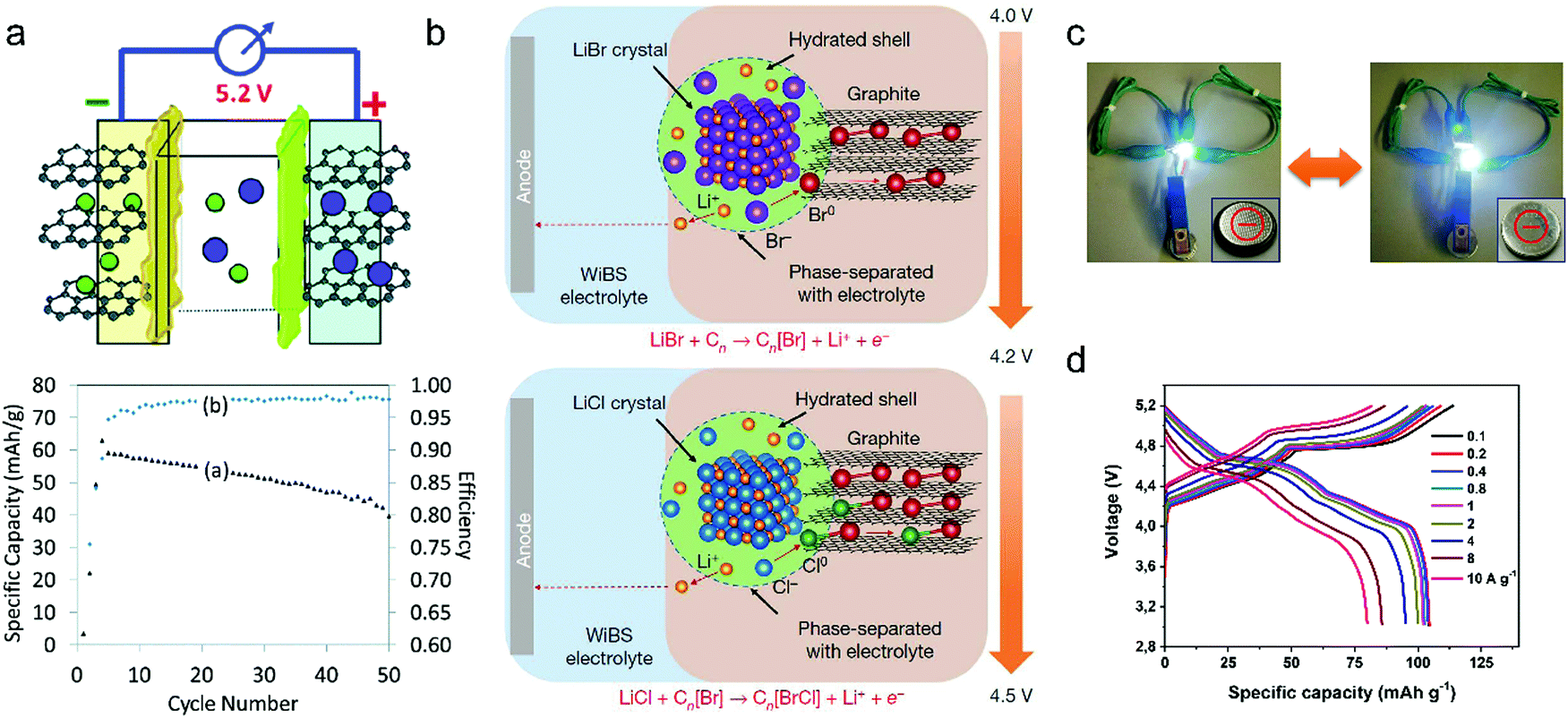 | ||
| Fig. 25 (a) Schematic illustration of a dual-graphite intercalation cell and its electrochemical performance. Reproduced from ref. 206 with permission from The Royal Society of Chemistry. (b) Schematic of the conversion–intercalation mechanism occurring in the composite graphite cathode during its oxidation in the water-in-bisalt aqueous-gel electrolyte. The two-stage reactions involve the oxidation of Br− (about 4.0 V) and Cl− (about 4.2 V) and their subsequent intercalation into the graphitic structure. The discharge is a complete reversal of the charge process. Reproduced from ref. 172 with permission from Springer Nature. (c) Powering a white light-emitting diode by the polarity-switchable symmetric graphite battery from both directions. Reproduced from ref. 376 with permission from Wiley-VCH. (d) Rate performance of the Li-ion pseudocapacitor in a voltage window of 3–5.2 V. Reproduced from ref. 163 with permission from Wiley-VCH. | ||
Very recently, a special C//C battery was reported, where a composite graphite cathode (LiBr, LiCl and graphite), a modified graphite anode and a “water-in-bisalt” electrolyte were involved (Fig. 25b).172 The highly concentrated aqueous electrolyte (21 mol kg−1 LiTFSI + 7 mol kg−1 LiOTf/water) played an essential role in this battery by providing high electrochemical oxidative stability up to 4.9 V (vs. Li+/Li) and being immiscible with LiBr and LiCl in the cathode or formed Br2 and BrCl, thus allowing Br− and Cl− to be oxidized to near-neutral states and intercalated into graphite. Note that such anion oxidation/intercalation reactions took place entirely inside the composite graphite cathode without anion uptake from the electrolyte. At the same time, Li+ diffused from the composite cathode to the graphite anode, behaving like a rocking-chair LIB. Because no SEI could be formed on the graphite anode in this electrolyte, the graphite anode was protected by a highly fluorinated ether polymer gel. The resultant full cell delivered a stable capacity of 127 mA h g−1 based on anode/cathode mass at an average voltage of 4.1 V (at 0.2C). After 150 cycles, the capacity retention was around 74% with a high average CE of 99.8%. If the mass of the cathode, anode and electrolyte was all counted, an energy density of 304 W h kg−1 could still be reached. This value is an energy record for C//C batteries or DIBs, highlighting the advantages of the proposed conversion–intercalation chemistry. Nevertheless, the stability, scalability, compatibility and processability of such energy technology based on concentrated aqueous electrolytes remain to be enhanced before its commercial implementations.
For large-capacity applications, C//C pouch cells with capacities of 60–1600 mA h were assembled using low-cost expanded graphite and/or MCMB as active materials and dilute carbonate solutions (1 M LiPF6) as electrolytes.203,378 The full cell exhibited high cycling stability, a wide operation temperature (−20 to 100 °C) and low self-discharge. Due to the robust chemical stability of graphite, these carbon materials could be recycled for further battery use, which largely decreased the cost of C//C batteries. At power densities of 48–584 W kg−1, the device energy density ranged from 47.9 to 54.1 W h kg−1 (the overall battery mass). Although the obtained energy density is lower than that (100–200 W h kg−1) of commercial LIBs, it is feasible to be promoted further by adopting concentrated electrolytes.
Potentially, C//C batteries can be symmetric batteries, which utilize the same active material as both anode and cathode. The main advantages of symmetric batteries lie in the largely simplified fabrication process, reduced manufacture cost379 and switchable polarity, which endows full cells with high tolerance against accidental polarity mix-up and thus high safety property. Our group first investigated the polarity switchability of the graphite electrode between cathode and anode.376 In a 2 M LiPF6 electrolyte with 3 wt% vinylene carbonate (VC), an activation process was noticed on the graphite electrode during the polarity switch, which was attributed to SEI formation and/or expanded graphite edges. As a consequence, the resultant symmetric graphite battery could perform from both charge directions and could be reversibly switched multi times on polarity (Fig. 25c). In addition to the polarity switchability function, our group also explored the fast charge capability of dual-graphite cells. By using a pre-lithiated graphite anode from the above polarity-switch activation process, a dual-graphite cell was built, which achieved a high operating voltage, impressive cycling stability and rate performance. Specifically, the middle discharge voltage (Vm) was as high as 4.50 V. The capacity retention was 96% after 1400 cycles at 1 A g−1. Additionally, the cell allowed fast charging within 30 s (10 A g−1) with 80% capacity retained (Fig. 25d). Because of the unique faradaic pseudocapacitive anion intercalation behavior of the graphite cathode we discovered before,221 we define such a dual-graphite system as a novel Li-ion pseudocapacitor,163 which outperforms activated carbon (AC)-derived Li-ion capacitors (LICs) and metal oxide pseudocapacitors in energy density and power density.
Other than the graphitic carbon anode, intercalative metal oxides like Li4Ti5O12,380 TiO2381 and MoO3382 were additionally analyzed as the anode for DIBs. Different from the graphite anode with a low discharge voltage (0.1 V vs. Li+/Li) and sluggish kinetics, the intercalative metal oxides mostly work above 1 V vs. Li+/Li but show high rate performance, thus avoiding Li dendrite formation and affording long cycling life (up to 10000 cycles) and fast charging capability of the full device. The drawback is the lower device voltage (Vm < 3.1 V) than that (Vm ∼ 4.5 V) of C//C batteries.
(2) Alloy-type anode//C batteries. As an important family of anode materials for Li+ storage, alloy-type anodes possess relatively low discharge potential (<0.4 V vs. Li+/Li) but high capacities due to their alloy reaction mechanism. Two representative examples for alloy-type anodes are Al and Si; both are abundant on earth and promising for scalable applications. The theoretical capacities for Al and Si are 2235 mA h g−1 (Li9Al4)384–386 and 3579 mA h g−1 (Li15Si4),387 respectively. The alloy-type anode//C (Al//C as an example) batteries work under eqn (22) and (23). Tang et al.383 first explored the use of the Al anode in DIBs with a battery configuration of Al//C (Fig. 26), where Al foil functioned as an anode and a current collector. Compared to C//C batteries, the Al//C batteries are simpler with respect to battery configuration. The VC additive was found to be effective in improving the cycling performance of the Al//C battery, which can be ascribed to VC-facilitated SEI formation of the Al anode. The final Al//C battery showed stable cycling performance at 0.5C with a Vm of 4.1 V, a high rate performance (1–5C) and a fair cycling life of 200 cycles. The formation of the AlLi alloy on the Al anode was confirmed in the half cells and full cells. To alleviate the pulverization of the Al anode during lithiation and delithiation, various Al anodes were constructed, like carbon-coated porous Al foil,388 bubble-like Al/C,389 3D Al deposited on glass fiber,390 modified Al foil391 and core–shell Al@C.392 The cycling life of Al//C batteries was successfully increased from <400 cycles to over 1000 cycles, and the rate capability was elevated to 20–120C. The remaining issue for Al//C batteries is the relatively low CE, especially at low current rates (<80% at 1–2C), which indicates the involvement of significant irreversible side reactions and continuous consumption of the electrolyte. One possible reason is the growth of the SEI on the Al anode during large volume variation.
| Cathode: A− + Cn ⇌ Cn+A− + e− | (22) |
| Anode: Li+ + Al + e− ⇌ Alx−Li+ | (23) |
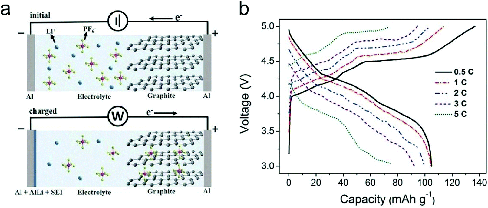 | ||
| Fig. 26 (a) Schematic illustration of the Al-graphite DIB in the initial and the charged states. (b) Charge–discharge curves of the Al-graphite DIB under 0.5, 1, 2, 3, and 5C. 1C corresponds to 100 mA g−1. Reproduced from ref. 383 with permission from Wiley-VCH. | ||
(3) Conversion-type or adsorption-type anode//C batteries. Conversion-type (WS2, MnSiO3)394,395 or adsorption-type anode (AC)396 materials also can be used in Li+-based DIBs. The electrode reactions in the WS2//C battery are shown as eqn (24) and (25). Since the working potential of these anodes was much higher (1.75 V vs. Li+/Li) than that of the graphite anode, the fabricated full cells show a limited Vm of ≤2 V. The irreversibility of the conversion-type anode generally will lead to huge polarization of full cells, giving rise to low energy efficiency.
| Cathode: A− + Cn ⇌ Cn+A− + e− | (24) |
| Anode: Li+ + 1/4WS2 + e− ⇌ 1/4W + 1/2Li2S | (25) |
(1) “Adsorption + intercalation”-type anode//C batteries. Due to the special chemical bonding change during the formation of Na+-GICs, pure Na+ intercalation into graphite encountered thermodynamic problems, leading to very limited capacity (12–35 mA h g−1).43 Alternatively, soft carbon and hard carbon398 containing crystalline graphitic domains but with much lower stacking order than graphite were applied as the anode materials for Na+-based DIBs and an “adsorption + insertion” mechanism was associated with soft carbon and hard carbon anodes. A soft carbon prepared by thermal polymerization of an organic compound showed a trace amount of oxygen (1.4%) and an interlayer distance of 0.39 nm.399 A high D band was noticed from Raman spectroscopy, indicating its high structural disorder. For Na storage, the soft carbon exhibited good rate capability and stable cycling performance (400 cycles) in half cells. Owing to the high working potential of soft carbon (0–1 V vs. Na+/Na), the soft carbon//C full cell exhibited a moderate Vm of 3.58 V in a dilute NaPF6/EC-DMC (1 M) electrolyte. In the voltage window of 2–4.7 V, the full cells delivered a maximum capacity of 103 mA h g−1 on soft carbon mass (52 mA h g−1 on graphite mass) and high capacity retention after 800 cycles. The capacity of full cells decayed much (from 100 to 56 mA h g−1) when elevating the current rate (from 200 to 1000 mA g−1). No typical three-region charge–discharge curve was noticed for the soft carbon//C cells, indicating incomplete utilization of the graphite cathode. Hard carbon from biomass (pine needles) was also fabricated, which showed a reversible capacity of 180 mA h g−1 for Na+ storage.400 The resultant hard carbon//C full cell in a dilute NaPF6/EC–EMC (1 M) electrolyte possessed a high Vm of 4.1 V (0.8–4.7 V) and long cycling life (87.2% capacity retention after 1000 cycles). By using PC as the electrolyte solvent (0.8 M NaPF6/PC), the Vm of hard carbon//C batteries can be increased to 4.3 V in a voltage window of 1.5–4.9 V.401
A nonflammable hard carbon//C battery based on NaTFSI was reported,397 which was enabled by the addition of nonflammable trimethyl phosphate (TMP). At a molar ratio of 1:2 (NaTFSI/TMP), the graphite cathode can form a stage-II GIC during TFSI− intercalation, while a stable SEI is formed on the hard carbon anode. The final hard carbon//C cell is capable of providing a Vm of 4.0 V and excellent electrochemical performance (Fig. 27a and b). However, the capacity of the hard carbon//C cell (46.6 mA h g−1 on graphite mass) is relatively low at the current stage, and further optimization of battery configuration may be needed. Besides soft carbon and hard carbon, our group recently demonstrated a dual-graphene Na+-based DIB.402 The electrochemically exfoliated graphene (EG) can reversibly store PF6− and Na+, endowing dual-graphite batteries with a 4.0 V working voltage. On account of the high processability of EG and the symmetric electrode feature, the dual-graphene battery can be readily printed for various miniaturized applications.
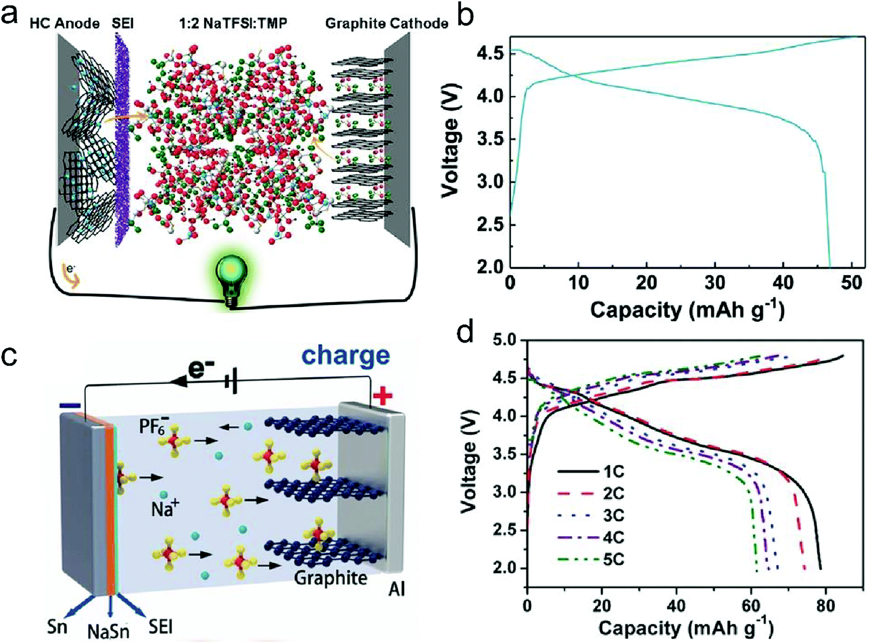 | ||
| Fig. 27 (a) Schematic illustration and (b) typical charge–discharge curves of Na+-dual carbon batteries using a 1:2 NaTFSI:TMP electrolyte at 500 mA g−1. Reproduced from ref. 397 with permission from Wiley-VCH. (c) Schematic illustration of the working mechanism and (d) charge–discharge curves of a Sn//C DIB at various current rates from 1 to 5C. Reproduced from ref. 197 with permission from Wiley-VCH. | ||
Other intercalation- or insertion-type Na+ hosts such as Na2Ti3O7,403 FePO4404 and FeFe(CN)6405 also find applications in DIBs. In the dilute carbonate and IL electrolyte (≤1 M), the full cells performed in the voltage range of 0–3.5 V, 1.2–4.2 V and 0.1–1.6 V and outputted a low Vm of 2.5 V, 2.3 V and 1.1 V, respectively.
(2) Alloy-type anode//C batteries. Sn, a conventional alloy type anode for LIBs, was studied as the Na host for DIBs. Theoretically, Sn can deliver a capacity of 847 mA h g−1 with a stoichiometry of Na15Sn4 and three intermediate phases (NaSn5, NaSn and Na9Sn4) exist.406 To enable Sn//C batteries, a dilute carbonate electrolyte (1 M NaPF6 in EC–DMC–EMC)197 was prepared, where EC plays a role in dissolving sodium salt and forming the SEI. The Sn foil//C cells operating under eqn (26) and (27) displayed a reversible capacity of 74 mA h g−1 at 2C over a voltage window of 2–4.8 V (Fig. 27c and d) and stable cycling performance with 94% capacity retained after 400 cycles. In spite of a relatively low Vm of 3.75 V than 4.0–4.3 V for hard carbon//C cells, Sn//C cells feature a simplified battery configuration and a few inactive components. As confirmed by XRD results, NaSn was formed during charging Sn//C cells. Compared to other alloy-type anodes (Pb and Sb), the full cells made from the Sn anode showed the highest reversible capacity, indicating the highest reactivity of Sn. To further push forward the electrochemical performance of Sn//C cells, a hybrid electrolyte (LiPF6 + NaPF6) was applied.407 The presence of more active Li+ (compared to Na+) in the electrolyte largely reduces the charge transfer resistance, eventually enhancing the rate capability (5C → 30C). The Vm of Sn//C cells was increased by 4.0 V due to the low reaction potential of LiSn.
| Cathode: PF6− + Cn ⇌ Cn+PF6− + e− | (26) |
| Anode: Na+ + Sn + e− ⇌ Na + Sn− | (27) |
(3) Conversion-type anode//C batteries. As a high-capacity conversion-type anode, MoS2 was used to build MoS2//C Na+-based DIBs.198,408 In the voltage windows of 1.0–4.0 V and 1.0–4.5 V, the MoS2//C cells exhibited a cycling life of 200–500 cycles but suffered from polarization problems. The charge–discharge separation exceeded 1–2 V and no obvious charge–discharge plateaus appeared.
(1) Intercalation-type anode//C batteries. Although the ionic radius of K+ (1.38 Å) is bigger than that (1.02 Å) of Na+,43 K+ intercalation into graphite is thermodynamically favorable, leading to a theoretical capacity of 279 mA h g−1 (KC8). C//C batteries in K+-based electrolytes have been demonstrated by different groups since 2017.200,409–411 A carbonate solution with 0.8–1 M KPF6 was applied as the electrolyte; EC was indispensable for its high solvation ability and SEI formation. The assembled C//C batteries showed a reversible capacity of 62 mA h g−1 (on anode mass; 31–41 mA h g−1 on cathode mass) in the voltage range of 3.0–5.0 V.410 A medium Vm of 3.96 V was achieved. Based on the charge–discharge curves and XRD data, the stage number of the charged graphite cathode in the K electrolyte is higher than stage-II, suggesting that the graphite cathode was not fully utilized. By expanding the voltage window to 3.0–5.2 V,200 the capacity of C//C batteries was enhanced to 61 mA h g−1 (based on the mass of the graphite cathode), and the Vm of C//C batteries was successfully increased by 4.5 V, which is comparable to that of C//C batteries in Li electrolytes. The remaining challenges for C//C batteries are further elevating the CE (>80%) and long-term cycling stability. The C//C cells were further built in K+-based IL electrolytes (0.3 M KTFSI in Pyr14TFSI) with 2 wt% ES.409Eqn (28) and (29) shows the electrochemical reaction of each electrode during cell operation. The electrochemical performance of the graphite anode and cathode was systematically investigated, where stage-I K+-GIC and >stage-II TFSI−-GIC were realized at 0.01–1.5 V and 3.4–5.0 V (vs. K+/K). The reversible capacities of the graphite anode and cathode stabilized around 230 and 45 mA h g−1 (at 50 mA g−1) with an average CE of 97%. Regarding the full cells, a stable capacity of 42 mA h g−1 and a long cycling life of 1500 cycles (95% capacity retention) were attained.
| Cathode: TFSI− + Cn ⇌ Cn+TFSI− + e− | (28) |
| Anode: K+ + C8 + e− ⇌ K+C8− | (29) |
(2) K//C batteries. For DIBs, the electrolyte containing active charge carriers (cations and anions) should be considered as the active material when calculating device-level energy density. The lower the concentration of the electrolyte, the more inactive the solvent involved, thus leading to low energy density of DIBs. The limited solubility of potassium salts in carbonates (NaPF6) and ILs (KTFSI) severely hinders the energy enhancement of K+-based DIBs. To address this problem, a concentrated KFSI electrolyte (5 M) was prepared in EC/DMC,167 where stage-I FSI−-GIC was formed when the graphite cathode was fully charged to 5.25 V vs. K+/K. On pairing the graphite cathode with a thin K foil anode, the K//C cells delivered a specific capacity of 98 mA h g−1, an average discharge voltage of 4.7 V and a cycling life of 300 cycles (Fig. 28). A high energy density of 207 W h kg−1 was claimed based on the mass of the graphite cathode and electrolyte. Due to the low ionic diffusion of the concentrated electrolyte, the rate capability of K//C cells was reasonable; around half capacity can be retained when the current was elevated from 0.05 to 0.5 A g−1 (Fig. 28c). The CE of K//C cells was found to decrease along with cycles from 99% to 93% (Fig. 28d), which was attributed to anodic corrosion even though a stable TiN coated current collector was employed. Anodic etching associated with corrosive anions remains a concern in DIBs, especially under lean electrolytes at the charged states. Note that K metal was used in this case; the dendrite formation issue of the K metal in carbonate electrolytes should be well deliberated in case of potential safety concerns.
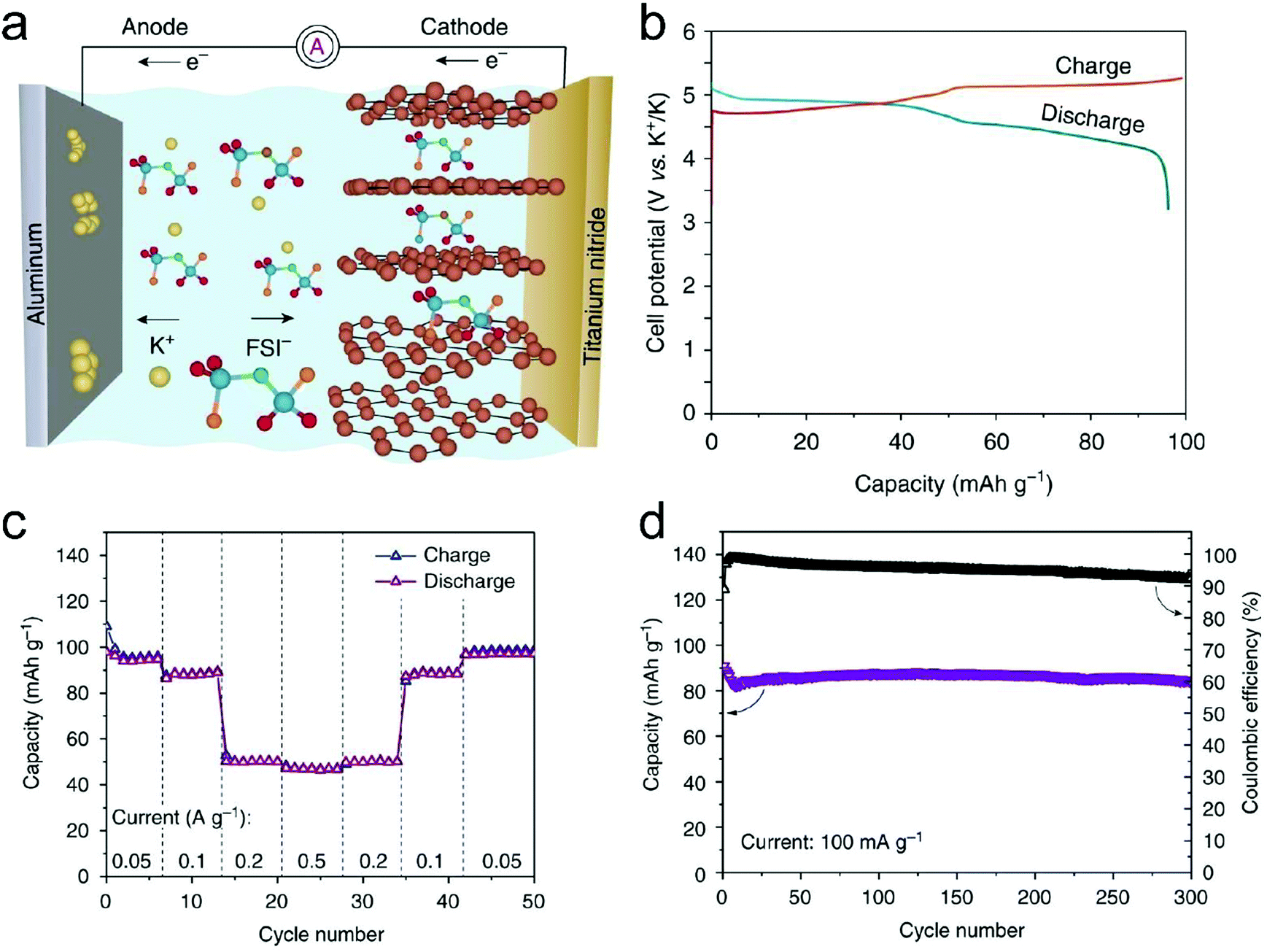 | ||
| Fig. 28 (a) Schematic of the charging process in a K//C DIB. Fluorine, oxygen, sulfur, and nitrogen atoms in the FSI− anion are shown in brown, red, blue, and green colors, respectively. (b) Typical galvanostatic voltage profile of a K//C DIB measured at a current density of 50 mA g−1. (c) Rate capability measurements and (d) cycling performance of a K//C DIB. Reproduced from ref. 167 with permission from Springer Nature. | ||
(3) Alloy-type anode//C batteries. Sn can be applied as a host for K+ storage other than Na+ storage. Using a similar work methodology to Sn//C Na+-based DIBs, a Sn//C K+-based DIB was reported,201 where 1 M KPF6 in EC–DMC–EMC was adopted as the electrolyte. The Sn//C cell gave a reversible capacity of 66 mA h g−1 (at 50 mA g−1) at 3.0–5.0 V and a Vm of 4.25 V, and it exhibited high cycling stability with 93% capacity retention after 300 cycles. To confirm the phase composition of the K–Sn alloy, four phases KSn4, KSn2, KSn and K2Sn were formed in the half cell while only K2Sn was noticed in the charged Sn//C DIB.
(4) Adsorption-type anode//C batteries. Regarding K+ storage kinetics, the adsorption-type anode possesses intrinsically fast rate capability than intercalation-type and alloy-type anodes, and thus the adsorption-type anode is appealing to construct high-power DIBs. Hierarchical porous carbon from pyrolysis of biomass and KOH activation manifested a high surface area of up to 3300 m2 g−1,412 leading to a stable capacity of 60.7–63 mA h g−1 independent of current density (0.5–3 A g−1). The final porous carbon//C hybrid cell displays very stable capacity up to 3 A g−1 and long-term cycling stability (74.2% capacity retention after 2000 cycles at 1 A g−1). Due to the high working potential (1–3 V vs. K+/K) of hierarchical porous carbon, the full hybrid cell works in a downshifted voltage window of 1.0–3.75 V with a Vm of 3.2 V.
| Cathode: AlCl4− + Cn ⇌ Cn+AlCl4− + e− | (30) |
| Anode: 4Al2Cl7− + 3e− ⇌ Al + 7AlCl4− | (31) |
:1, there is Al2Cl7− formed in the acidic IL, which enables Al electroplating and thus an AIB. During charging, Al2Cl7− in the electrolyte was consumed and Al was deposited on the anode, while AlCl4− was intercalated into graphitic carbon cathodes. The maximum ratio of AlCl3/EMImCl is 2:1, beyond which, AlCl3 did not dissolve in the IL. It was revealed that a high-ratio AlCl3/EMImCl electrolyte led to a declined onset voltage of the AIB,214 and the maximum capacity was obtained at an optimal ratio of 1.3:1.170 The resultant Al//graphene-foam AIB exhibited a reversible capacity of 66 mA h g−1 and well-defined discharge plateaus at 2 V (Fig. 29b). The AIB could even operate at 4 A g−1 (<1 min charge/discharge) for 7500 cycles without capacity fading. The CE stabilizes at 90% at 100 mA g−1 and approaches 98% at high current rates (5 A g−1; Fig. 29c).
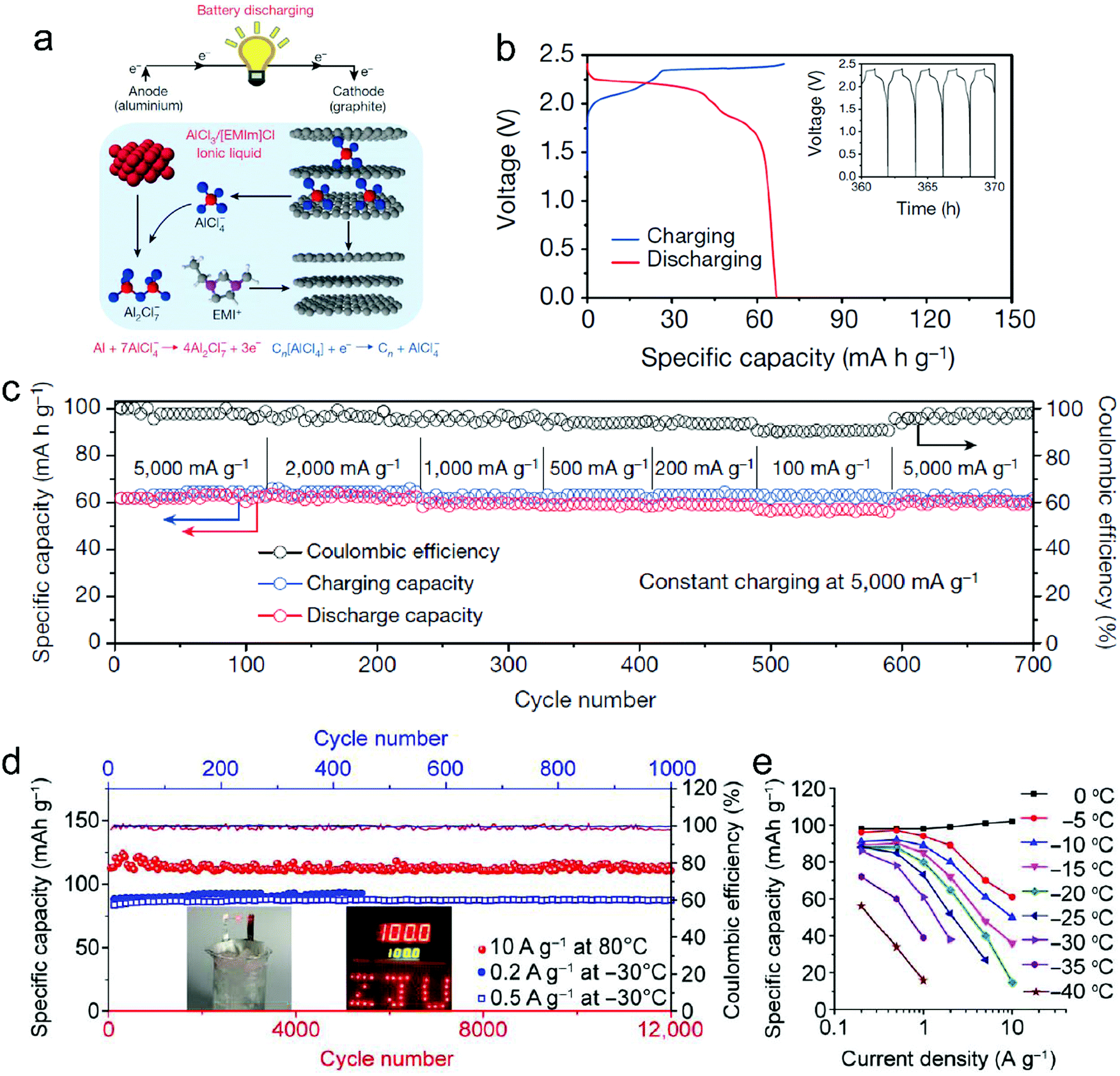 | ||
| Fig. 29 (a) Schematic drawing of the Al/graphite cell during discharge, using the optimal composition of the AlCl3/EMImCl IL electrolyte. (b) Galvanostatic charge and discharge curves of an Al/pyrolytic graphite (PG) Swagelok cell at a current density of 66 mA g−1. Inset, charge and discharge cycles. (c) An Al/graphitic-foam pouch cell charging at 5000 mA g−1 and discharging at current densities ranging from 100 to 5000 mA g−1. Reproduced from ref. 170 with permission from Springer Nature. (d) Stable cycling of the GF-HC cathode at 80 °C (red, 12000 cycles) and −30 °C (blue, 1000 cycles). Inset: Al-GB soft pack cells successfully igniting LED lights in an ice-salt bath and a 100 °C oven. (e) Summary of specific capacities and rate capability of the GF-HC cathode at different temperatures below 0 °C. Reproduced from ref. 169 with permission from AAAS. | ||
To further boost the capacity and rate capability of AIBs, various graphitic carbons with higher GD189,214,416,417 and rationally designed interlayer spacing/porous structure97,169,234,240,418,419 were adopted. The capacity was increased to 110–150 mA h g−1 and the current rate can be as high as 400 A g−1169 at low mass loading. As Al plating/stripping takes place on the anode side of AIBs, the Al anode can be replaced by any other substrate that facilitates reversible electroplating of Al. C//C AIBs have been demonstrated recently.29,420 For large capacity application, an industrialized prototype AIB with a capacity of 1.3 A h was assembled using a carbon paper cathode and Al foil.421 The Ah-level AIB exhibited stable cycling performance at 10 mA g−1 for over 100 cycles with a CE of 93%. The capacity of AIBs decreased to 0.73 Ah at an elevated current density of 40 mA g−1. The self-discharge rate of the AIB was estimated to be 5.89–7.23% per day. It is important to note that, after 120 cycles, the carbon paper turned into thin-layer graphene due to expansion and exfoliation of the graphite cathode. Similar large expansion of the graphite cathode was noticed before.170 It appears that currently only AlCl4− intercalation into graphite causes exfoliation of graphite, which is rarely reported in other anion systems (PF6−, TFSI−, FTFSI−, FSI−, BF4− and Br−0.05Cl−0.25). The large di may be the main reason (Table 1). Owing to the use of IL electrolytes, the AIBs show impressive electrochemical performance under extreme conditions; the AIBs can survive the drill experiment during battery operation170 and even heating under an alcohol lamp.234 The broad liquid range of IL electrolytes further makes AIBs capable of performing within a wide temperature range of −40 to 120 °C (Fig. 29d and e),169 which is suitable for all-climate energy storage applications.
To reduce the cost of IL electrolytes for AIBs, new electrolyte systems including AlCl3–urea190,422 AlCl3–urea–[EMIm]Cl,423 AlCl3/Et3NHCl424 and inorganic molten salts (AlCl3–NaCl,425 AlCl3–NaCl–KCl191 and AlCl3–LiCl–KCl426) are explored. The AIB based on the AlCl3–urea electrolyte190 displays a Vm of 1.73 V (vs. 2 V in AlCl3/EMImCl) and a specific capacity of 73 mA h g−1 at 100 mA g−1. Correspondingly, a stage-II AlCl4−-GIC was achieved when fully charged. Al deposition proceeded through two pathways, one involving Al2Cl7− and the other involving [AlCl2·(urea)n]+. The ionic conductivity remained to be further promoted due to high viscosity. In the AlCl3–urea electrolyte at 120 °C, it is found that the capacity of the AIB was enhanced to 93 mA h g−1 with improved rate capability.422 Another room temperature AlCl3/Et3NHCl electrolyte led to a high upper cut-off voltage of 2.62 V. The Al//rGO AIB exhibited a high capacity of 112 mA h g−1, a Vm of 1.9 V and a long lifespan (30000 cycles).424 In the inorganic molten electrolytes, the graphite-derived AIBs operated at 95–120 °C delivered capacities of 100–128 mA h g−1 and a Vm of 1.35–1.75 V.
Similar to DIBs, all the active charge carriers (Al2Cl7− and AlCl4−) of AIBs are initially stored in the IL electrolyte. So the energy density of AIBs strongly depends on the electrolyte. Taking the AlCl3/EMImCl electrolyte as an example, the ratio of AlCl3/EMImCl predetermines the content of Al2Cl7− in the electrolyte. Assuming a Vm of 2 V and a graphitic capacity of 140 mA h g−1, the energy density of the Al//C AIB based on the mass of the electrolyte and graphite cathode was maximized (72 W h kg−1) at the ratio of 2:1 and was around 33 W h kg−1 at 1.3:1. Note that most AIBs run at the ratio of 1.3:1, and the low energy density is currently the key challenge for AIBs.
| Cathode: PF6− + Cn ⇌ Cn+PF6− + e− | (32) |
| Anode: 7Ca2+ + 6Sn + 14e− ⇌ Ca72+Sn62.33− | (33) |
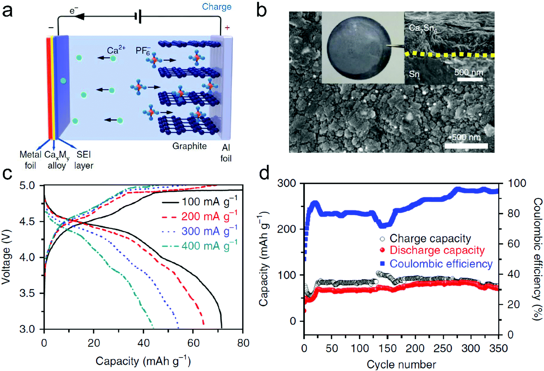 | ||
| Fig. 30 (a) Work schematics of the proposed Sn//C cell. Graphite was used as the cathode material for PF6− intercalation/deintercalation, and a metal foil that could form an alloy with Ca was used as both current collector and anode. The green, blue and orange balls represent Ca, F and P atoms, respectively. (b) SEM images of the Sn foil anode after 300 cycles. The dashed yellow line shows the interface between Sn and Ca7Sn6. (c) Charge–discharge performance at different current densities ranging from 100 to 400 mA g−1 and (d) cycling stability of the Sn//C cell at 100 mA g−1. Reproduced from ref. 202 with permission from Springer Nature. | ||
Further, a Ca2+-based DIB with a dual-graphite configuration429 was constructed. Conventional MCMB was applied as the anode to host Ca2+ in the carbonate electrolyte (0.7 M Ca(PF6)2 in EC–DMC–EMC). During charging, the (002) peak of pristine graphite shifted from 26.3° to 25.9°, and a profound Ca signal was noticed in the charged MCMB anode. Based on these results, the authors concluded that Ca2+ was intercalated into MCMB. Thoroughgoing characterization of the Ca2+-GIC is highly recommended due to the fact that no electrochemical intercalation of pure Ca2+ into the graphite host has been reported so far and Ca2+/solvent co-intercalation430 has been just revealed in a 0.5 M Ca(BH4)2 dimethylacetamide electrolyte very recently.
To get rid of anodic oxidation and make full use of the graphite cathode, our group recently developed a hybrid carbonate electrolyte (EMC) containing Zn(TFSI)2 and LiPF6−.431 The presence of LiPF6 efficiently suppresses the anodic oxidation of Zn(TFSI)2 and leads to a super-wide electrochemical stability window of 4 V (vs. Zn2+/Zn), which is much higher than those of the above two IL electrolytes. Nuclear magnetic resonance (NMR) spectroscopy measurements indicates that PF6− diffuses faster than TFSI− in the hybrid electrolyte, thus protecting the current collector from anodic oxidation by the formation of a PF6−-derived passivation film. Both dendrite-free Zn plating/stripping and reversible dual-anion (TFSI− and PF6−) intercalation are realized in the hybrid electrolyte. And the formation of stage-I TFSI−/PF6−-GIC was confirmed by XRD, NMR and XPS results. The electrode reactions can be summarized as eqn (34) and (35).
| Cathode: PF6− + TFSI− + Cn ⇌ Cn2+(PF6−)(TFSI−) + 2e− | (34) |
| Anode: Zn2+ + 2e− ⇌ Zn | (35) |
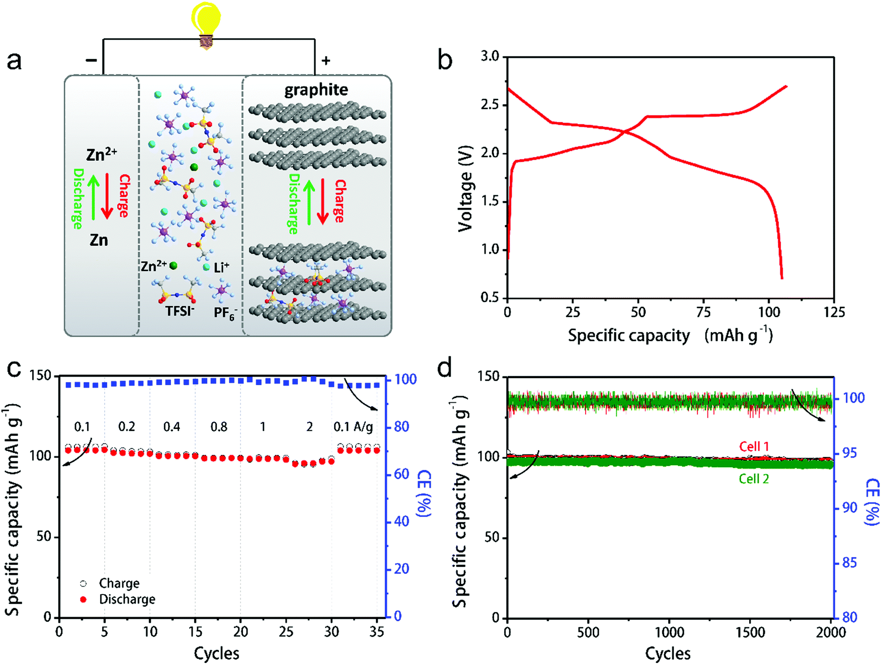 | ||
| Fig. 31 (a) Schematic illustration of the Zn-graphite battery configuration and electrode reactions. (b) Typical charge–discharge curve at 100 mA g−1, (c) rate capability and (d) cycling performance of the Zn-graphite battery at 1000 mA g−1. Reproduced from ref. 431 with permission from Wiley-VCH. | ||
(1) Intercalation-type anode//C batteries. As early as 1994, Carlin et al.440 proposed dual-intercalating IL batteries with room-temperature or low-temperature ILs as the only electrolytes. ILs consist of active charge carriers (cations and anions), and no additional salt or solvent is needed. They investigated various ILs including EMIm+, 1,2-dimethyl-3-propylimidazolium cations (DMPI+), AlCl4−, PF6−, CF3SO3− and C6H5CO2−. Reversible DMPI+ intercalation into graphite was evidenced by CV and charge–discharge curves. The dual-graphite cell employing the DMPI+AlCl4− electrolyte showed a Vm of 2.9 V and a cycling efficiency of 85% at 1.5–3.8 V. The detailed electrode reactions are shown as eqn (36) and (37).
| Cathode: ACl4− + Cn ⇌ Cn+ACl4− + e− | (36) |
| Anode: DMPI+ + Cm + e− ⇌ DMPI+Cm− | (37) |
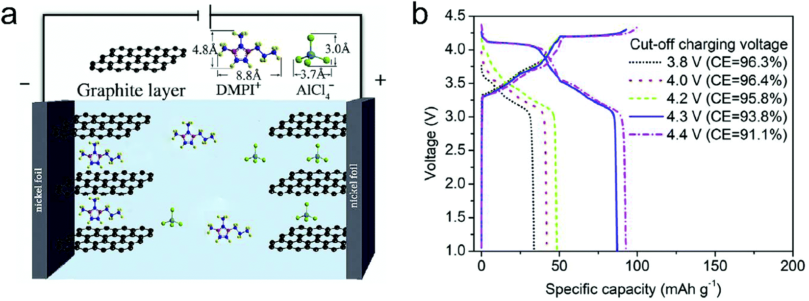 | ||
| Fig. 32 (a) Operation principle of the DIB containing (DMPI+)(AlCl4−) as an IL electrolyte. (b) Charge/discharge curves of the DIB cell at cut-off charging voltages of 3.8–4.4 V. Reproduced from ref. 439 with permission from Elsevier. | ||
The C//C batteries appear to work in other ILs, such as 1-butyl-1-methylpiperidinium bis(trifluoromethylsulfonyl)imide (PP14TFSI) and Pyr14TFSI.441,442 There are multiple plateaus on the charge–discharge curves, which, however, were not well explained and characterized. IL decomposition was noticed in the disassembled cells, especially for the PP14TFSI system, while capacity fading is quite fast in Pyr14TFSI-derived cells. MoS2 can also serve as the anode to host EMIm+ cations. The as-formed MoS2//C cell in the EMIm+TFSI− electrolyte delivered a maximum capacity of 77 mA h g−1 and a moderate cycle life of 300 cycles. Fundamentally, it is important to reveal in the future how EMIm+ is intercalated into MoS2, which may work for other complex cations and inspire further investigation over other layered compounds.
(2) Insertion-type or adsorption-type anode//C batteries. Besides inorganic layered materials, an organic compound, 5,7,12,14-pentacenetetrone (PCT), was applied as the complex cation host.443 During charging, the Pyr14+ will be inserted into the PCT anode while TFSI− will intercalate into the graphite cathode (eqn (38) and (39)). The PCT//C cell shows a relatively stable overall performance of 100 cycles with a Vm of 2.2 V. The maximum capacity of the PCT//C cell was 165 mA h g−1 (on anode mass), around half value of its theoretical capacity (317 mA h g−1). Similar to the C//C cell in DMPI+AlCl4−, the PCT//C cell in Pyr14+TFSI− suffers from a quick self-discharge rate (4.7% h−1).
| Cathode: TFSI− + Cn ⇌ Cn+TFSI− + e− | (38) |
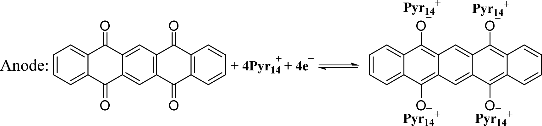 | (39) |
5. Conclusions
Overall, carbon materials hold great opportunities in the applications of numerous rechargeable energy storage technologies owing to the large abundance, low-cost raw materials, structural tailorability as well as the diverse redox electrochemistry (cation intercalation and anion intercalation). Currently, LIBs are dominating the rechargeable battery market, and post-LIBs (including NIBs, KIBs, DIBs, and AIBs) also show great potential in particular application fields. The energy density of post-LIBs remains to be enhanced to compete with LIBs, but the cost can be largely reduced, which is especially desirable for grid-scale applications. In this respect, the utilization of carbon electrodes would strengthen the low-cost advantage of post-LIBs, facilitating their fast penetration into commercialization. In the case of donor-type intercalation, carbon materials serve as superior anode hosts for alkali metal cations (Li+, Na+, and K+). Following a similar development roadmap, research on various cation-storage carbon materials all started with graphite, with the motivation to obtain a fundamental understanding of the cation-storage mechanism. Subsequently, extensive efforts have been devoted to exploring novel carbon nanostructures and their hybrids/superstructures for hosting alkali metal cations, which covers nanosized carbon, nanoporous carbon, disordered carbon, heteroatom-doped carbon, etc. It should be pointed out that disordered carbon with partial graphitization properties has dominated the research trend of cation-intercalation carbon, as these disordered carbon materials can offer plentiful active sites and a shortened diffusion path. The state-of-the-art disordered carbon anodes have demonstrated record-high reversible capacity (>1000 mA h g−1) and ultralong cycling stability (>1000 cycles).In the case of acceptor-type intercalation, the main focus has been put on the mechanism investigation and the corresponding energy storage devices (DIBs and AIBs). Compared to conventional Li-rich transition metal oxide cathodes in LIBs, the main advantages of graphitic carbon cathodes lie in high working potential (≥5 V vs. Li+/Li), excellent electrical conductivity, high structure/chemical stability and excellent compatibility. Various anions have been electrochemically intercalated into graphitic carbon cathodes. By pairing graphitic carbon with appropriate anode materials and specific electrolyte systems, various DIBs/AIBs can be constructed to achieve particular performance such as non-flammability, polarity-switchability, fast-charging ability, flexibility, and operation under extreme temperatures. Nanostructured carbons with well-designed porous channels, crystallinity and chemical composition have shown impressive cycling and rate performance for anion storage due to their facilitated volume accommodation and ion diffusion. It is noteworthy that the volumetric capacity of nanostructured carbons remains to be further enhanced because of their low density. The heteroatom-doping effect on graphitic carbon, which was comprehensively investigated in carbon anodes, is not well understood for the carbon cathode. At the contemporary infancy stage of DIBs and AIBs, more efforts on designing novel carbon materials, understanding the ion-intercalation process/ion packing states and elevating the electrochemical performance of energy storage devices are crucially needed.
Cation-intercalation carbon materials
(a) The cation-storage chemistry of carbon materials is a complex integration of intercalation, adsorption, coordination, and clustering, which necessitates further in-depth investigations to guide and promote the development of high-performance carbon anodes. Although it has been well accepted that micropores, interlayer distance, disorder degree, and heteroatom doping play important roles in affecting the cation-storage behavior of carbon materials (e.g. ion diffusion pathways, electrode/electrolyte interface chemistry, and cation storage modes), the individual contribution and the optimal parameters of these influencing factors have not been well defined. Clearly, the identification of the optimal parameters for the best cation-storage behavior requires carbon materials with well-controlled atom-level and morphology-level properties and advanced (in situ) characterization techniques. Moreover, computational simulation/calculation is also critically important to offer a quantitative prospect for the further optimization of carbon materials. The acquired mechanism understanding will, in turn, provide a great guidance for the innovative design of carbon structures for cation storage.(b) A fast increase in the number of reports has been witnessed on developing novel carbon anodes for LIBs, NIBs and KIBs in the last few years. In most cases, large specific surface area, rich carbon defects, high porosity, and heteroatom doping were pursued. However, the main drawback for these carbon materials cannot be overlooked, which is the low first-cycle CE (ranging from 40% to 80%) due to the large irreversible capacity. In practical full-cell applications, the large irreversible capacity of the anode must be compensated by using cathode materials in excess. After the first cycle, the presence of a dead mass of cathode material would result in the low overall capacity of the full cell. Meanwhile, disordered carbon anodes also suffer from the hysteresis between charge and discharge potential, which causes the constructed full cell to have a sloping voltage profile and low energy efficiency. Moreover, nanoporous carbon materials have a rich interparticle space and low tap density, which increases the interparticle electron-transport resistance and electrode thickness. These factors would hinder the development of battery electrodes with high loading mass and high volumetric capacity. Priority should be put on the understanding and investigation of these issues associated with carbon anodes. A precise control of carbon microstructures is clearly needed for improving the capacity of carbon structures without the sacrifice of the first-cycle CE, potential platform, and volumetric performance.
(c) Searching for next-generation intercalation form is also of great interest in the near future, which aims to develop carbon anodes with high intercalation capacity, low intercalation potential, fast charge-transfer kinetics, and superior chemical stability. It imposes a high demand for the innovation of topological carbon structures, guest ions, and electrolyte solvents. Some initial theoretical studies have been carried out to predict the cation-storage behavior of novel carbon nanostructures like nodal-line carbon449 and 5-8-5 carbon rings,299 which depict a superior cation-storage behavior than graphite. These studies would inspire the experimental efforts on the synthesis and investigations of novel carbon materials. It remains unexplored how the intercalation proceeds for carbon materials in a multi guest-ion environment, which may provide promising directions for the performance optimization of carbon anodes. Moreover, the electrolyte also has a significant influence on ionic conductivity, ion solvation, SEI formation, etc. Developing novel electrolyte concepts (e.g. organic solvents, novel additives, IL, concentrated electrolytes, liquid-state, solid-state) can also potentially change the cation-intercalation form of carbon anodes.
Anion-intercalation carbon materials
(a) The reported diffusion coefficient of different anions in graphitic carbon varies in a very broad range from 10−4 (for AlCl4−) to 10−15 cm2 s−1 (for TFSI−). However, the fundamental reason remains to be revealed. A detailed diffusion investigation or simulation on a model graphitic carbon material like HOPG will be helpful to understand the kinetic difference between different anions. Further, anion intercalation will bring about high-volume change (100–140%) of the graphitic carbon cathode, which is much higher than that due to alkaline cation intercalation. Engineering on the porous structure of graphitic carbon and electrode porosity is demanded to solve the disintegration issue, especially at high mass loadings. Freestanding yet robust graphitic carbon with 3D interconnected porous channels and fair density is highly desirable to alleviate structural degradation during large volume variation and achieve high volumetric capacity, if inactive conductive additive, binder and metallic current collector can be removed. Currently, graphite remains the best carbon material for the anion host due to its extremely low cost, balanced performance and excellent compatibility to nowadays infrastructures of LIBs. Further chemical modification of graphite by heteroatom doping like B and graphitic N may introduce more active sites for anion storage.(b) Due to the strong electrostatic repulsion between anions, the specific capacity of the graphitic carbon cathode currently is less than 150 mA h g−1, which cannot meet the demand for high-energy cathode materials. Replacing redox-inactive anions with redox-active halogen atoms is an efficient solution. Further exploring redox-active anions remains a feasible way to enhance the capacity of graphitic carbon cathodes. An unavoidable problem associated with anion-intercalation carbon materials is the low CE, which can be attributed to the self-discharge issue of carbon cathodes and/or side reactions (e.g., electrolyte decomposition or current collector etching) at high potentials. The self-discharge issue of anion-intercalation carbon cathodes refers to the self-deintercalation of anions from carbon hosts, which is accompanied by a continuous voltage drop of batteries. Theoretical simulation may help predict the most stable anion-intercalated structure, which can be readily implemented by voltage control of energy devices. More investigations are also suggested to optimize the chemical composition of carbon, charge protocol, and battery operation/storage condition. Regarding the electrolyte decomposition and anodic etching, screening current collectors, adopting highly stable electrolytes (e.g., F-containing solvents or additives), and engineering interphase are encouraged in the future to suppress side reactions during anion intercalation into carbon cathodes.
(c) The charge–discharge profiles and CV curves of the graphite cathode during PF6− and AlCl4− intercalation/deintercalation are quite similar, except different potential ranges.163,189,221 The stable capacity of graphite in both cases is very close (∼100 mA h g−1). However, the stage number of PF6−-GIC is stage-I while it is stage-II/III/IV for AlCl4−-GIC when fully charged. Considering the larger size of AlCl4− over PF6−, additional efforts may be needed to analyze the packing state of AlCl4− between graphite interlayers and to re-evaluate the volume expansion of the AlCl4−-GIC.
Ion-intercalation carbon-based rechargeable batteries
(a) Most of the studies on cation-intercalation carbon are limited in material-level evaluation with half-cell tests; only few research studies on full-cell exploration have been performed to demonstrate the availability of the carbon anode for practical energy storage devices. Partial reason could be the low first-cycle CE of the obtained carbon anode. Anyhow, we hope that this review could draw more research attention to the full cell exploration, rather than only material side. Particular emphasis should be focused on the configuration optimization, cell-level performance metrics, and degradation mechanism. The acquired knowledge at the cell level will speed up the transition of new proof-of-concept carbon anode design and device design to scalable applications.(b) Energy density has been the driving force that motivates battery development in the last 200 years. Calculating the energy density of DIBs and AIBs based only on the mass of electrodes will lead to overrated values because the electrolyte as an active material contributes notable weight, especially in dilute electrolyte systems. Therefore, a concentrated electrolyte or even a solid-state electrolyte is preferable for high-energy DIBs and AIBs. One remarkable strategy to boost the energy densities of carbon electrode-based batteries was recently demonstrated by hybridizing the Li+-containing cathode (LiFePO4) with the graphite cathode. The integration of Li+-deintercalation and PF6−-intercalation in the hybrid cathode favours the enhanced capacity and broadened voltage window, thus increasing the energy density of full cells by 35%.450 To push forward the energy density of carbon-based full cells, innovation on carbon materials merely is insufficient. Multidisciplinary efforts on materials, chemistry, and engineering are necessary to exploit novel ion hosts, electrolytes, electrochemistry, and battery configurations. Constructing hybrid cathodes to introduce conversion/intercalation chemistry is a successful example. Another potential option lies in rocking-chair carbon-based anion batteries, which perform under lean electrolytes with anions as charge carriers. The selection of anion charge carriers, host materials, and electrolyte systems needs to be rationally considered.
(c) Currently, the CE of DIBs and AIBs is not satisfactory, which is mainly inherited from carbon cathodes. The low CE leads to the low energy efficiency and limited span life of full devices with lean electrolytes. C//C batteries are the most promising systems for commercial application, as they offer the lowest cost and the highest operation voltage. The expense on electrolytes should be counted as well when assessing the device-level cost and Na and K-based salts are preferred over Li salts for such purpose. The present AIBs are based on a redox couple of Al2Cl7−/Al (−0.7 V vs. SHE), rather than Al3+/Al (−1.66 V vs. SHE).451 The potential gap is nearly 1 V. Under theoretical conditions, the Al3+-based DIBs are anticipated to possess a higher Vm than the current Al2Cl7−-based AIBs (3 V vs. 2 V). The requisite is reversible Al plating and stripping in the Al3+-based electrolyte with negligible polarization.
(d) The cycling performance of most demonstrated devices is evaluated under a flooded electrolyte. The mass of the electrolyte at least needs to match with the capacity of charge carrier hosts. The impact of electrolyte amount on overall electrochemical performance (cycling and energy density) should be evaluated, which is important to offer a balance point for practical devices.
List of abbreviations
| 1D | One-dimensional |
| 2D | Two-dimensional |
| 3D | Three-dimensional |
| AC | Activated carbon |
| AIBs | Al-ion batteries |
| BET | Brunauer–Emmett–Teller |
| BETI− | Bis(pentafluoroethanesulfonyl)imide |
| B | Boron |
| C//C | Dual-carbon |
| CE | Coulombic efficiency |
| CNTs | Carbon nanotubes |
| CV | Cyclic voltammetry |
| CVD | Chemical vapor deposition |
| DEC | Diethyl carbonate |
| DFT | Density functional theory |
| DIBs | Dual-ion batteries |
| DMC | Dimethyl carbonate |
| DME | Dimethyl ether |
| DMPI+ | 1,2-Dimethyl-3-propylimidazolium cations |
| DOL | 1,3-Dioxolane |
| EC | Ethyl carbonate |
| EG | Electrochemically exfoliated graphene |
| EIS | Electrochemical impedance spectroscopy |
| EMC | Ethyl methyl carbonate |
| EMImCl | 1-Ethyl-3-methylimidazolium chloride |
| EMImTfO | 1-Ethyl-3-methylimidazolium trifluoromethanesulfonate |
| EQCM | Electrochemical quartz crystal microbalance |
| FEC | Monofluoroethylene carbonate |
| FSI− | Bis(fluorosulfonyl)imide |
| FTFSI− | Fluorosulfonyl-(trifluoromethanesulfonyl)imide |
| GD | Graphitization degree |
| GIC | Graphite intercalation compound |
| GITT | Galvanostatic intermittent titration technique |
| GO | Graphite oxide |
| HOMO | Highest occupied molecular orbital |
| HOPG | Highly oriented pyrolytic graphite |
| IL | Ionic liquid |
| IUPAC | International Union of Pure and Applied Chemistry |
| KIBs | K-ion batteries |
| LIBs | Li-ion batteries |
| LICs | Li-ion capacitors |
| LiTfO | Lithium trifluoromethanesulfonate |
| MCMB | Mesocarbon microbeads |
| MWCNTs | Multi-walled CNTs |
| NIB | Na-ion battery |
| NMR | Nuclear magnetic resonance spectroscopy |
| PAN | Polyacrylonitrile |
| PC | Propylene carbonate |
| PC | Propylene carbonate |
| PCT | 5,7,12,14-Pentacenetetrone |
| PG | Pyrolytic graphite |
| PP14TFSI | 1-Butyl-1-methylpiperidinium bis(trifluoromethylsulfonyl)imide |
| Pyr14TFSI | N-Butyl-N-methylpyrrolidinium bis(trifluoromethanesulfonyl)imide |
| rGO | Reduced graphene oxide |
| SEI | Solid electrolyte interphase |
| SEM | Scanning electron microscope |
| SWCNTs | Single-walled CNTs |
| TEM | Transmission electron microscope |
| TFSI− | Bis(trifluoromethanesulfonyl)imide |
| TMP | Trimethyl phosphate |
| VC | Vinylene carbonate |
| XRD | X-ray diffraction |
| XPS | X-ray photoelectron spectroscopy |
| XAS | X-ray adsorption spectroscopy |
Conflicts of interest
There are no conflicts to declare.Acknowledgements
This work was financially supported by European Union's Horizon 2020 research and innovation programme (GrapheneCore3 881603), ERC Consolidator grant (T2DCP 819698), M-ERA.NET and Sächsisches Staatsministerium für Wissenschaft und Kunst (HYSUCAP 100478697), and German Research Foundation (DFG) within the Cluster of Excellence, CRC 1415 (grant no. 417590517), and Polymer-based Batteries (SPP 2248, RACOF-MMIS).Notes and references
- B. Obama, Science, 2017, 355, 126–129 CrossRef CAS.
- M. Yu, R. Dong and X. Feng, J. Am. Chem. Soc., 2020, 142, 12903–12915 CrossRef CAS.
- W. Liu, L. Yu, R. Yin, X. Xu, J. Feng, X. Jiang, D. Zheng, X. Gao, X. Gao, W. Que, P. Ruan, F. Wu, W. Shi and X. Cao, Small, 2020, 16, e1906775 CrossRef.
- M. Yu and X. Feng, Joule, 2019, 3, 338–360 CrossRef CAS.
- M. Yu, H. Shao, G. Wang, F. Yang, C. Liang, P. Rozier, C. Z. Wang, X. Lu, P. Simon and X. Feng, Nat. Commun., 2020, 11, 1348 CrossRef CAS.
- M. Yu, N. Chandrasekhar, R. K. M. Raghupathy, K. H. Ly, H. Zhang, E. Dmitrieva, C. Liang, X. Lu, T. D. Kuhne, H. Mirhosseini, I. M. Weidinger and X. Feng, J. Am. Chem. Soc., 2020, 142(46), 19570–19578 CrossRef CAS.
- E. Pomerantseva, F. Bonaccorso, X. Feng, Y. Cui and Y. Gogotsi, Science, 2019, 366, DOI:10.1126/science.aan8285.
- H. Zhang, W. Wu, Q. Liu, F. Yang, X. Shi, X. Liu, M. Yu and X. Lu, Angew. Chem., Int. Ed., 2020 DOI:10.1002/anie.202010073.
- W. Shi, X. Liu, T. Deng, S. Huang, M. Ding, X. Miao, C. Zhu, Y. Zhu, W. Liu, F. Wu, C. Gao, S. W. Yang, H. Y. Yang, J. Shen and X. Cao, Adv. Mater., 2020, 32, e1907404 CrossRef.
- J. Liu, Z. Bao, Y. Cui, E. J. Dufek, J. B. Goodenough, P. Khalifah, Q. Li, B. Y. Liaw, P. Liu, A. Manthiram, Y. S. Meng, V. R. Subramanian, M. F. Toney, V. V. Viswanathan, M. S. Whittingham, J. Xiao, W. Xu, J. Yang, X.-Q. Yang and J.-G. Zhang, Nat. Energy, 2019, 4, 180–186 CrossRef CAS.
- Y. Liu, Y. Zhu and Y. Cui, Nat. Energy, 2019, 4, 540–550 CrossRef.
- Z. Yang, J. Zhang, M. C. Kintner-Meyer, X. Lu, D. Choi, J. P. Lemmon and J. Liu, Chem. Rev., 2011, 111, 3577–3613 CrossRef CAS.
- S. Kalaiselvam and R. Parameshwaran, Thermal Energy Storage Technologies for Sustainability, 2014, pp. 21–56 DOI:10.1016/b978-0-12-417291-3.00002-5.
- C. P. Grey and J. M. Tarascon, Nat. Mater., 2016, 16, 45–56 CrossRef CAS.
- Z. Yang, J. Ren, Z. Zhang, X. Chen, G. Guan, L. Qiu, Y. Zhang and H. Peng, Chem. Rev., 2015, 115, 5159–5223 CrossRef CAS.
- Y. Han, Z. Lai, Z. Wang, M. Yu, Y. Tong and X. Lu, Chem. – Eur. J., 2018, 24, 7312–7329 CrossRef CAS.
- J. Ni and Y. Li, Adv. Energy Mater., 2016, 6, 1600278 CrossRef.
- Y. Li, K. Yan, H.-W. Lee, Z. Lu, N. Liu and Y. Cui, Nat. Energy, 2016, 1, 15029 CrossRef CAS.
- H. Jin, S. Xin, C. Chuang, W. Li, H. Wang, J. Zhu, H. Xie, T. Zhang, Y. Wan, Z. Qi, W. Yan, Y.-R. Lu, T.-S. Chan, X. Wu, J. B. Goodenough, H. Ji and X. Duan, Science, 2020, 370, 192–197 CrossRef CAS.
- H. Li, T. Yamaguchi, S. Matsumoto, H. Hoshikawa, T. Kumagai, N. L. Okamoto and T. Ichitsubo, Nat. Commun., 2020, 11, 1584 CrossRef.
- W. Wei, G. Wang, S. Yang, X. Feng and K. Mullen, J. Am. Chem. Soc., 2015, 137, 5576–5581 CrossRef CAS.
- R. Xu, G. Wang, T. Zhou, Q. Zhang, H.-P. Cong, X. Sen, J. Rao, C. Zhang, Y. Liu, Z. Guo and S.-H. Yu, Nano Energy, 2017, 39, 253–261 CrossRef CAS.
- P. Poizot, S. Laruelle, S. Grugeon, L. Dupont and J. M. Tarascon, Nature, 2000, 407, 496–499 CrossRef CAS.
- Y. M. Chen, X. Y. Yu, Z. Li, U. Paik and X. W. Lou, Sci. Adv., 2016, 2, e1600021 CrossRef.
- G. Wang, J. Zhang, S. Yang, F. Wang, X. Zhuang, K. Müllen and X. Feng, Adv. Energy Mater., 2018, 8, 1702254 CrossRef.
- G. Wang, Y. Sun, D. Li, W. Wei, X. Feng and K. Müllen, Small, 2016, 12, 3914–3919 CrossRef CAS.
- W. Rüdorff and U. Hofmann, Z. Anorg. Allg. Chem., 1938, 238, 1–50 CrossRef.
- I. A. Rodríguez-Pérez and X. Ji, ACS Energy Lett., 2017, 2, 1762–1770 CrossRef.
- M. Wang and Y. Tang, Adv. Energy Mater., 2018, 8, 1703320 CrossRef.
- F. P. McCullough Jr and A. F. Beale Jr, US 4865931A, 1989.
- P. Jiménez, E. Levillain, O. Alévêque, D. Guyomard, B. Lestriez and J. Gaubicher, Angew. Chem., Int. Ed., 2017, 56, 1553–1556 CrossRef.
- H. Gao, L. Xue, S. Xin and J. B. Goodenough, Angew. Chem., Int. Ed., 2018, 57, 5449–5453 CrossRef CAS.
- M. Walter, K. V. Kravchyk, C. Böfer, R. Widmer and M. V. Kovalenko, Adv. Mater., 2018, 30, 1705644 CrossRef.
- S. Muench, A. Wild, C. Friebe, B. Häupler, T. Janoschka and U. S. Schubert, Chem. Rev., 2016, 116, 9438–9484 CrossRef CAS.
- P. Poizot, J. Gaubicher, S. Renault, L. Dubois, Y. Liang and Y. Yao, Chem. Rev., 2020, 120, 6490–6557 CrossRef CAS.
- H. Liu, X. Liu, W. Li, X. Guo, Y. Wang, G. Wang and D. Zhao, Adv. Energy Mater., 2017, 7, 1700283 CrossRef.
- N. A. Kaskhedikar and J. Maier, Adv. Mater., 2009, 21, 2664–2680 CrossRef CAS.
- J. Kim, M. S. Choi, K. H. Shin, M. Kota, Y. Kang, S. Lee, J. Y. Lee and H. S. Park, Adv. Mater., 2019, 31, e1803444 CrossRef.
- H. Hou, X. Qiu, W. Wei, Y. Zhang and X. Ji, Adv. Energy Mater., 2017, 7, 1602898 CrossRef.
- D. Saurel, B. Orayech, B. Xiao, D. Carriazo, X. Li and T. Rojo, Adv. Energy Mater., 2018, 8, 1703268 CrossRef.
- J. C. Pramudita, D. Sehrawat, D. Goonetilleke and N. Sharma, Adv. Energy Mater., 2017, 7, 1602911 CrossRef.
- X. Wu, Y. Chen, Z. Xing, C. W. K. Lam, S. S. Pang, W. Zhang and Z. Ju, Adv. Energy Mater., 2019, 9, 1900343 CrossRef.
- Y. Li, Y. Lu, P. Adelhelm, M. M. Titirici and Y. S. Hu, Chem. Soc. Rev., 2019, 48, 4655–4687 RSC.
- A. Yacoby, Nat. Phys., 2011, 7, 925–926 Search PubMed.
- R. C. Dante, Handbook of Friction Materials and their Applications, 2016, pp. 93–103 DOI:10.1016/b978-0-08-100619-1.00007-9.
- K. S. Novoselov, A. K. Geim, S. V. Morozov, D. Jiang, Y. Zhang, S. V. Dubonos, I. V. Grigorieva and A. A. Firsov, Science, 2004, 306, 666–669 CrossRef CAS.
- C. Lee, X. Wei, J. W. Kysar and J. Hone, Science, 2008, 321, 385–388 CrossRef CAS.
- K. I. Bolotin, K. J. Sikes, Z. Jiang, M. Klima, G. Fudenberg, J. Hone, P. Kim and H. L. Stormer, Solid State Commun., 2008, 146, 351–355 CrossRef CAS.
- M. D. Stoller, S. Park, Y. Zhu, J. An and R. S. Ruoff, Nano Lett., 2008, 8, 3498–3502 CrossRef CAS.
- K. Ji, J. Han, A. Hirata, T. Fujita, Y. Shen, S. Ning, P. Liu, H. Kashani, Y. Tian, Y. Ito, J. I. Fujita and Y. Oyama, Nat. Commun., 2019, 10, 275 CrossRef.
- F. Yao, F. Gunes, H. Q. Ta, S. M. Lee, S. J. Chae, K. Y. Sheem, C. S. Cojocaru, S. S. Xie and Y. H. Lee, J. Am. Chem. Soc., 2012, 134, 8646–8654 CrossRef CAS.
- A. L. Reddy, A. Srivastava, S. R. Gowda, H. Gullapalli, M. Dubey and P. M. Ajayan, ACS Nano, 2010, 4, 6337–6342 CrossRef CAS.
- W. S. Hummers and R. E. Offeman, J. Am. Chem. Soc., 1958, 80, 1339 CrossRef CAS.
- D. R. Dreyer, S. Park, C. W. Bielawski and R. S. Ruoff, Chem. Soc. Rev., 2010, 39, 228–240 RSC.
- J. N. Coleman, Acc. Chem. Res., 2013, 46, 14–22 CrossRef CAS.
- K. R. Paton, E. Varrla, C. Backes, R. J. Smith, U. Khan, A. O'Neill, C. Boland, M. Lotya, O. M. Istrate, P. King, T. Higgins, S. Barwich, P. May, P. Puczkarski, I. Ahmed, M. Moebius, H. Pettersson, E. Long, J. Coelho, S. E. O'Brien, E. K. McGuire, B. M. Sanchez, G. S. Duesberg, N. McEvoy, T. J. Pennycook, C. Downing, A. Crossley, V. Nicolosi and J. N. Coleman, Nat. Mater., 2014, 13, 624–630 CrossRef CAS.
- S. Yang, A. G. Ricciardulli, S. Liu, R. Dong, M. R. Lohe, A. Becker, M. A. Squillaci, P. Samori, K. Mullen and X. Feng, Angew. Chem., Int. Ed., 2017, 56, 6669–6675 CrossRef CAS.
- S. Iijima, Nature, 1991, 354, 56–58 CrossRef CAS.
- A. P. Graham, G. S. Duesberg, W. Hoenlein, F. Kreupl, M. Liebau, R. Martin, B. Rajasekharan, W. Pamler, R. Seidel, W. Steinhoegl and E. Unger, Appl. Phys. A: Mater. Sci. Process., 2005, 80, 1141–1151 CrossRef CAS.
- R. Zhang, Y. Zhang, Q. Zhang, H. Xie, W. Qian and F. Wei, ACS Nano, 2013, 7, 6156–6161 CrossRef CAS.
- T. W. Odom, J.-L. Huang, P. Kim and C. M. Lieber, Nature, 1998, 391, 62–64 CrossRef CAS.
- M. Xu, D. N. Futaba, M. Yumura and K. Hata, Adv. Mater., 2011, 23, 3686–3691 CrossRef CAS.
- K. Uetani, S. Ata, S. Tomonoh, T. Yamada, M. Yumura and K. Hata, Adv. Mater., 2014, 26, 5857–5862 CrossRef CAS.
- J.-C. Charlier, X. Blase and S. Roche, Rev. Mod. Phys., 2007, 79, 677–732 CrossRef CAS.
- T. Guo, P. Nikolaev, A. Thess, D. T. Colbert and R. E. Smalley, Chem. Phys. Lett., 1995, 243, 49–54 CrossRef CAS.
- S. Fan, M. G. Chapline, N. R. Franklin, T. W. Tombler, A. M. Cassell and H. Dai, Science, 1999, 283, 512–514 CrossRef CAS.
- H. Dai, A. G. Rinzler, P. Nikolaev, A. Thess, D. T. Colbert and R. E. Smalley, Chem. Phys. Lett., 1996, 260, 471–475 CrossRef CAS.
- K. Hata, D. N. Futaba, K. Mizuno, T. Namai, M. Yumura and S. Iijima, Science, 2004, 306, 1362–1364 CrossRef CAS.
- C.-M. Seah, S.-P. Chai and A. R. Mohamed, Carbon, 2011, 49, 4613–4635 CrossRef CAS.
- G. D. Nessim, Nanoscale, 2010, 2, 1306–1323 RSC.
- E. Irisarri, A. Ponrouch and M. R. Palacin, J. Electrochem. Soc., 2015, 162, A2476–A2482 CrossRef CAS.
- M. Yu, Y. Huang, C. Li, Y. Zeng, W. Wang, Y. Li, P. Fang, X. Lu and Y. Tong, Adv. Funct. Mater., 2015, 25, 324–330 CrossRef CAS.
- J. Gilbert, J. Kipling, B. McEnaney and J. Sherwood, Polymer, 1962, 3, 1–10 CrossRef CAS.
- J. J. Kipling, J. N. Sherwood, P. V. Shooter and N. R. Thompson, Carbon, 1964, 1, 315–320 CrossRef CAS.
- F. G. Emmerich, Carbon, 1995, 33, 1709–1715 CrossRef CAS.
- L. Chen, S. Yang, J. Huang, W. Xie, B. Ding, Y. Liu, F. Xu and Y. Liang, Mater. Lett., 2018, 232, 187–190 CrossRef CAS.
- M. Yu, Y. Lu, H. Zheng and X. Lu, Chem. – Eur. J., 2018, 24, 3639–3649 CrossRef CAS.
- F. Xu, B. Ding, Y. Qiu, J. Wu, Z. Cheng, G. Jiang, H. Li, X. Liu, B. Wei and H. Wang, Langmuir, 2019, 35, 12889–12897 CrossRef CAS.
- K. Sing, D. Everett, R. Haul, L. Moscou, R. Pierotti, J. Rouquerol and T. Siemieniewska, Pure Appl. Chem., 1985, 57, 603 CAS.
- W. Wang, J. Zhou, Z. Wang, L. Zhao, P. Li, Y. Yang, C. Yang, H. Huang and S. Guo, Adv. Energy Mater., 2018, 8, 1701648 CrossRef.
- G. Wang, Y. Sun, D. Li, H. W. Liang, R. Dong, X. Feng and K. Mullen, Angew. Chem., Int. Ed., 2015, 54, 15191–15196 CrossRef CAS.
- Y. Meng, D. Gu, F. Zhang, Y. Shi, H. Yang, Z. Li, C. Yu, B. Tu and D. Zhao, Angew. Chem., Int. Ed., 2005, 44, 7053–7059 CrossRef CAS.
- A. Stein, B. E. Wilson and S. G. Rudisill, Chem. Soc. Rev., 2013, 42, 2763–2803 RSC.
- Y. Zhu, S. Murali, M. D. Stoller, K. J. Ganesh, W. Cai, P. J. Ferreira, A. Pirkle, R. M. Wallace, K. A. Cychosz, M. Thommes, D. Su, E. A. Stach and R. S. Ruoff, Science, 2011, 332, 1537–1541 CrossRef CAS.
- F. Xu, Z. Tang, S. Huang, L. Chen, Y. Liang, W. Mai, H. Zhong, R. Fu and D. Wu, Nat. Commun., 2015, 6, 7221 CrossRef.
- S. Román, J. F. González, C. M. González-García and F. Zamora, Fuel Process. Technol., 2008, 89, 715–720 CrossRef.
- N. Sun, Z. Guan, Y. Liu, Y. Cao, Q. Zhu, H. Liu, Z. Wang, P. Zhang and B. Xu, Adv. Energy Mater., 2019, 9, 1901351 CrossRef.
- R. E. Franklin, Nature, 1956, 177, 239 CrossRef CAS.
- M. Audier, A. Oberlin, M. Oberlin, M. Coulon and L. Bonnetain, Carbon, 1981, 19, 217–224 CrossRef CAS.
- F. J. Maldonado-Hódar, C. Moreno-Castilla, J. Rivera-Utrilla, Y. Hanzawa and Y. Yamada, Langmuir, 2000, 16, 4367–4373 CrossRef.
- M. Sevilla and A. B. Fuertes, Carbon, 2006, 44, 468–474 CrossRef CAS.
- T.-H. Kim, E. K. Jeon, Y. Ko, B. Y. Jang, B.-S. Kim and H.-K. Song, J. Mater. Chem. A, 2014, 2, 7600–7605 RSC.
- Y. Wen, K. He, Y. Zhu, F. Han, Y. Xu, I. Matsuda, Y. Ishii, J. Cumings and C. Wang, Nat. Commun., 2014, 5, 4033 CrossRef CAS.
- X. Qi, J. Qu, H.-B. Zhang, D. Yang, Y. Yu, C. Chi and Z.-Z. Yu, J. Mater. Chem. A, 2015, 3, 15498–15504 RSC.
- L. Wang, Y. Zhu, C. Guo, X. Zhu, J. Liang and Y. Qian, ChemSusChem, 2014, 7, 87–91 CrossRef CAS.
- F. Wang, J. Yi, Y. Wang, C. Wang, J. Wang and Y. Xia, Adv. Energy Mater., 2014, 4, 1300600 CrossRef.
- Y. Wu, M. Gong, M. C. Lin, C. Yuan, M. Angell, L. Huang, D. Y. Wang, X. Zhang, J. Yang, B. J. Hwang and H. Dai, Adv. Mater., 2016, 28, 9218–9222 CrossRef CAS.
- T. Nakajima and Y. Matsuo, Carbon, 1994, 32, 469–475 CrossRef CAS.
- B. M. Way and J. R. Dahn, J. Electrochem. Soc., 1994, 141, 907–912 CrossRef CAS.
- U. Tanaka, T. Sogabe, H. Sakagoshi, M. Ito and T. Tojo, Carbon, 2001, 39, 931–936 CrossRef CAS.
- J. V. Rani, V. Kanakaiah, T. Dadmal, M. S. Rao and S. Bhavanarushi, J. Electrochem. Soc., 2013, 160, A1781–A1784 CrossRef CAS.
- E. Peled, C. Menachem, D. Bar-Tow and A. Melman, J. Electrochem. Soc., 1996, 143, L4–L7 CrossRef CAS.
- T. H. N. G. Amaraweera, N. W. B. Balasooriya, H. W. M. A. C. Wijayasinghe, A. N. B. Attanayake, B.-E. Mellander and M. A. K. L. Dissanayake, Ionics, 2018, 24, 3423–3429 CrossRef CAS.
- B. Dyatkin, J. Halim and J. A. Read, J. Carbon Resour., 2017, 3, 11 CrossRef.
- Y. Cao, L. Xiao, X. Ai and H. Yang, Electrochem. Solid-State Lett., 2003, 6, A30–A33 CrossRef CAS.
- Q. Pan, H. Wang and Y. Jiang, J. Mater. Chem., 2007, 17, 329–334 RSC.
- F. Ding, W. Xu, D. Choi, W. Wang, X. Li, M. H. Engelhard, X. Chen, Z. Yang and J.-G. Zhang, J. Mater. Chem., 2012, 22, 12745–12751 RSC.
- G. Song, J. Ryu, S. Ko, B. M. Bang, S. Choi, M. Shin, S.-Y. Lee and S. Park, Chem. – Asian J., 2016, 11, 1711–1717 CrossRef CAS.
- Y. S. Kim, S. H. Kim, G. Kim, S. Heo, J. Mun, S. Han, H. Jung, Y. K. Kyoung, D. J. Yun, W. J. Baek and S. Doo, ACS Appl. Mater. Interfaces, 2016, 8, 30980–30984 CrossRef CAS.
- D. C. Elias, R. R. Nair, T. M. G. Mohiuddin, S. V. Morozov, P. Blake, M. P. Halsall, A. C. Ferrari, D. W. Boukhvalov, M. I. Katsnelson, A. K. Geim and K. S. Novoselov, Science, 2009, 323, 610–613 CrossRef CAS.
- H. Wang, Y. Zhou, D. Wu, L. Liao, S. Zhao, H. Peng and Z. Liu, Small, 2013, 9, 1316–1320 CrossRef CAS.
- X. Wang, G. Sun, P. Routh, D.-H. Kim, W. Huang and P. Chen, Chem. Soc. Rev., 2014, 43, 7067–7098 RSC.
- Y. Li, Y. Yuan, Y. Bai, Y. Liu, Z. Wang, L. Li, F. Wu, K. Amine, C. Wu and J. Lu, Adv. Energy Mater., 2018, 8, 1702781 CrossRef.
- H. Hou, L. Shao, Y. Zhang, G. Zou, J. Chen and X. Ji, Adv. Sci., 2017, 4, 1600243 CrossRef.
- Z. Li, L. Ma, T. W. Surta, C. Bommier, Z. Jian, Z. Xing, W. F. Stickle, M. Dolgos, K. Amine, J. Lu, T. Wu and X. Ji, ACS Energy Lett., 2016, 1, 395–401 CrossRef CAS.
- H. Liu, M. Jia, N. Sun, B. Cao, R. Chen, Q. Zhu, F. Wu, N. Qiao and B. Xu, ACS Appl. Mater. Interfaces, 2015, 7, 27124–27130 CrossRef CAS.
- J. S. Sander, R. M. Erb, L. Li, A. Gurijala and Y. M. Chiang, Nat. Energy, 2016, 1, 16099 CrossRef CAS.
- Y. Kuang, C. Chen, D. Kirsch and L. Hu, Adv. Energy Mater., 2019, 9, 1901457 CrossRef.
- J. Billaud, F. Bouville, T. Magrini, C. Villevieille and A. R. Studart, Nat. Energy, 2016, 1, 16097 CrossRef CAS.
- C. Schafhaeutl, J. Prakt. Chem., 1840, 21, 129–157 CrossRef.
- Y. Matsuda, J. Electrochem. Soc., 1981, 128, 2552 CrossRef CAS.
- M. Winter, J. O. Besenhard, M. E. Spahr and P. J. A. m. Novak, Adv. Mater., 1998, 10, 725–763 CrossRef CAS.
- T. Ohzuku, J. Electrochem. Soc., 1993, 140, 2490 CrossRef CAS.
- H. Kim, J. Hong, G. Yoon, H. Kim, K.-Y. Park, M.-S. Park, W.-S. Yoon and K. Kang, Energy Environ. Sci., 2015, 8, 2963–2969 RSC.
- Z. Jian, W. Luo and X. Ji, J. Am. Chem. Soc., 2015, 137, 11566–11569 CrossRef CAS.
- H. P. Boehm, R. Setton and E. Stumpp, Pure Appl. Chem., 1994, 66, 1893–1901 CAS.
- N. Daumas and A. Herold, C. R. Hebd. Seances Acad. Sci., Ser. C, 1969, 268, 373 CAS.
- C. Sole, N. E. Drewett and L. J. Hardwick, Faraday Discuss., 2014, 172, 223–237 RSC.
- J. A. Read, J. Phys. Chem. C, 2015, 119, 8438–8446 CrossRef CAS.
- J. A. Seel and J. R. Dahn, J. Electrochem. Soc., 2000, 147, 892–898 CrossRef CAS.
- X. Y. Song, J. Electrochem. Soc., 1996, 143, L120 CrossRef CAS.
- M. Kuhne, F. Borrnert, S. Fecher, M. Ghorbani-Asl, J. Biskupek, D. Samuelis, A. V. Krasheninnikov, U. Kaiser and J. H. Smet, Nature, 2018, 564, 234–239 CrossRef.
- R. Raccichini, A. Varzi, S. Passerini and B. Scrosati, Nat. Mater., 2015, 14, 271–279 CrossRef CAS.
- J. R. Dahn, T. Zheng, Y. Liu and J. S. Xue, Science, 1995, 270, 590–593 CrossRef CAS.
- K. Sato, M. Noguchi, A. Demachi, N. Oki and M. Endo, Science, 1994, 264, 556–558 CrossRef CAS.
- T. Kar, J. Pattanayak and S. Scheiner, J. Phys. Chem. A, 2001, 105, 10397–10403 CrossRef CAS.
- K. Nishidate and M. Hasegawa, Phys. Rev. B: Condens. Matter Mater. Phys., 2005, 71, 245418 CrossRef.
- B. Song, J. Yang, J. Zhao and H. Fang, Energy Environ. Sci., 2011, 4 CAS.
- J. Zhao, A. Buldum, J. Han and J. Ping Lu, Phys. Rev. Lett., 2000, 85, 1706–1709 CrossRef CAS.
- C. Garau, A. Frontera, D. Quiñonero, A. Costa, P. Ballester and P. M. Deyà, Chem. Phys. Lett., 2003, 374, 548–555 CrossRef CAS.
- T. Zheng, J. N. Reimers and J. R. Dahn, Phys. Rev. B: Condens. Matter Mater. Phys., 1995, 51, 734–741 CrossRef CAS.
- T. Zheng, J. Electrochem. Soc., 1995, 142, 2581 CrossRef CAS.
- T. Zheng, W. Xing and J. R. Dahn, Carbon, 1996, 34, 1501–1507 CrossRef CAS.
- E. Peled, J. Electrochem. Soc., 1979, 126, 2047 CrossRef CAS.
- Z. Wang, S. M. Selbach and T. Grande, RSC Adv., 2014, 4, 3973–3983 RSC.
- Y. Liu, B. V. Merinov and W. A. Goddard 3rd, Proc. Natl. Acad. Sci. U. S. A., 2016, 113, 3735–3739 CrossRef CAS.
- D. A. Stevens and J. R. Dahn, J. Electrochem. Soc., 2001, 148, A803 CrossRef CAS.
- C. Bommier, T. W. Surta, M. Dolgos and X. Ji, Nano Lett., 2015, 15, 5888–5892 CrossRef CAS.
- Y. Sun, J. Tang, K. Zhang, J. Yuan, J. Li, D. M. Zhu, K. Ozawa and L. C. Qin, Nanoscale, 2017, 9, 2585–2595 RSC.
- Y. Cao, L. Xiao, M. L. Sushko, W. Wang, B. Schwenzer, J. Xiao, Z. Nie, L. V. Saraf, Z. Yang and J. Liu, Nano Lett., 2012, 12, 3783–3787 CrossRef CAS.
- Y.-X. Wang, S.-L. Chou, H.-K. Liu and S.-X. Dou, Carbon, 2013, 57, 202–208 CrossRef CAS.
- A. P. Cohn, K. Share, R. Carter, L. Oakes and C. L. Pint, Nano Lett., 2016, 16, 543–548 CrossRef CAS.
- Z. Zhu, F. Cheng, Z. Hu, Z. Niu and J. Chen, J. Power Sources, 2015, 293, 626–634 CrossRef CAS.
- B. Jache and P. Adelhelm, Angew. Chem., Int. Ed., 2014, 53, 10169–10173 CrossRef CAS.
- H. Kim, J. Hong, Y.-U. Park, J. Kim, I. Hwang and K. Kang, Adv. Funct. Mater., 2015, 25, 534–541 CrossRef CAS.
- G. Yoon, H. Kim, I. Park and K. Kang, Adv. Energy Mater., 2017, 7, 1601519 CrossRef.
- D. A. Stevens and J. R. Dahn, J. Electrochem. Soc., 2000, 147, 1271 CrossRef CAS.
- Y. Xie, Y. Chen, L. Liu, P. Tao, M. Fan, N. Xu, X. Shen and C. Yan, Adv. Mater., 2017, 29, 1702268 CrossRef.
- J. Yang, X. Zhou, D. Wu, X. Zhao and Z. Zhou, Adv. Mater., 2017, 29, 1604108 CrossRef.
- W. Luo, J. Wan, B. Ozdemir, W. Bao, Y. Chen, J. Dai, H. Lin, Y. Xu, F. Gu, V. Barone and L. Hu, Nano Lett., 2015, 15, 7671–7677 CrossRef CAS.
- K. Share, A. P. Cohn, R. Carter, B. Rogers and C. L. Pint, ACS Nano, 2016, 10, 9738–9744 CrossRef CAS.
- H. S. Kim, J. B. Cook, H. Lin, J. S. Ko, S. H. Tolbert, V. Ozolins and B. Dunn, Nat. Mater., 2017, 16, 454–460 CrossRef CAS.
- G. Wang, S. Oswald, M. Loffler, K. Mullen and X. Feng, Adv. Mater., 2019, 31, e1807712 CrossRef.
- D. Zhu, L. Zhang, Y. Huang, J. Li, H. Fan and H. Wang, ACS Appl. Energy Mater., 2019, 2, 8031–8038 CrossRef CAS.
- S. Rothermel, P. Meister, G. Schmuelling, O. Fromm, H.-W. Meyer, S. Nowak, M. Winter and T. Placke, Energy Environ. Sci., 2014, 7, 3412–3423 RSC.
- T. Placke, G. Schmuelling, R. Kloepsch, P. Meister, O. Fromm, P. Hilbig, H.-W. Meyer and M. Winter, Z. Anorg. Allg. Chem., 2014, 640, 1996–2006 CrossRef CAS.
- K. V. Kravchyk, P. Bhauriyal, L. Piveteau, C. P. Guntlin, B. Pathak and M. V. Kovalenko, Nat. Commun., 2018, 9, 4469 CrossRef.
- C.-J. Pan, C. Yuan, G. Zhu, Q. Zhang, C.-J. Huang, M.-C. Lin, M. Angell, B.-J. Hwang, P. Kaghazchi and H. Dai, Proc. Natl. Acad. Sci. U. S. A., 2018, 115, 5670–5675 CrossRef CAS.
- H. Chen, H. Xu, S. Wang, T. Huang, J. Xi, S. Cai, F. Guo, Z. Xu, W. Gao and C. Gao, Sci. Rep., 2017, 3, 7233 Search PubMed.
- M.-C. Lin, M. Gong, B. Lu, Y. Wu, D.-Y. Wang, M. Guan, M. Angell, C. Chen, J. Yang, B.-J. Hwang and H. Dai, Nature, 2015, 520, 324–328 CrossRef CAS.
- G. A. Elia, I. Hasa, G. Greco, T. Diemant, K. Marquardt, K. Hoeppner, R. J. Behm, A. Hoell, S. Passerini and R. Hahn, J. Mater. Chem. A, 2017, 5, 9682–9690 RSC.
- C. Yang, J. Chen, X. Ji, T. P. Pollard, X. Lü, C.-J. Sun, S. Hou, Q. Liu, C. Liu, T. Qing, Y. Wang, O. Borodin, Y. Ren, K. Xu and C. Wang, Nature, 2019, 569, 245–250 CrossRef CAS.
- T. Placke, A. Heckmann, R. Schmuch, P. Meister, K. Beltrop and M. Winter, Joule, 2018, 2, 2528–2550 CrossRef CAS.
- B. Ozmen Monkul, Dissertation, Oregon State University, 2010.
- G. Schmuelling, T. Placke, R. Kloepsch, O. Fromm, H.-W. Meyer, S. Passerini and M. Winter, J. Power Sources, 2013, 239, 563–571 CrossRef CAS.
- G. Furdin, B. Bach and A. Herold, C. R. Acad. Sci. Paris C, 1970, 271, 683 CAS.
- J. Zheng, M. H. Engelhard, D. Mei, S. Jiao, B. J. Polzin, J.-G. Zhang and W. Xu, Nat. Energy, 2017, 2, 17012 CrossRef CAS.
- H.-J. Liao, Y.-M. Chen, Y.-T. Kao, J.-Y. An, Y.-H. Lai and D.-Y. Wang, J. Phys. Chem. C, 2017, 121, 24463–24469 CrossRef CAS.
- T. Placke, O. Fromm, S. F. Lux, P. Bieker, S. Rothermel, H.-W. Meyer, S. Passerini and M. Winter, J. Electrochem. Soc., 2012, 159, A1755–A1765 CrossRef CAS.
- T. Placke, S. Rothermel, O. Fromm, P. Meister, S. F. Lux, J. Huesker, H.-W. Meyer and M. Winter, J. Electrochem. Soc., 2013, 160, A1979–A1991 CrossRef CAS.
- P. Meister, V. Siozios, J. Reiter, S. Klamor, S. Rothermel, O. Fromm, H.-W. Meyer, M. Winter and T. Placke, Electrochim. Acta, 2014, 130, 625–633 CrossRef CAS.
- O. Fromm, P. Meister, X. Qi, S. Rothermel, J. Huesker, H. W. Meyer, M. Winter and T. Placke, ECS Trans., 2014, 58, 55–65 CrossRef.
- K. Beltrop, P. Meister, S. Klein, A. Heckmann, M. Grünebaum, H.-D. Wiemhöfer, M. Winter and T. Placke, Electrochim. Acta, 2016, 209, 44–55 CrossRef CAS.
- X. Wang, E. Yasukawa and S. Mori, Electrochim. Acta, 2000, 45, 2677–2684 CrossRef CAS.
- L. PÉTer and J. Arai, J. Appl. Electrochem., 1999, 29, 1053–1061 CrossRef.
- P. W. Ruch, M. Hahn, F. Rosciano, M. Holzapfel, H. Kaiser, W. Scheifele, B. Schmitt, P. Novák, R. Kötz and A. Wokaun, Electrochim. Acta, 2007, 53, 1074–1082 CrossRef CAS.
- Y. Huang, H. Fan, H. Kamezaki, B. Kang, M. Yoshio and H. Wang, ChemElectroChem, 2019, 6, 2931–2936 CrossRef CAS.
- L. Zhang, J. Li, Y. Huang, D. Zhu and H. Wang, Langmuir, 2019, 35, 3972–3979 CrossRef CAS.
- D.-Y. Wang, C.-Y. Wei, M.-C. Lin, C.-J. Pan, H.-L. Chou, H.-A. Chen, M. Gong, Y. Wu, C. Yuan, M. Angell, Y.-J. Hsieh, Y.-H. Chen, C.-Y. Wen, C.-W. Chen, B.-J. Hwang, C.-C. Chen and H. Dai, Nat. Commun., 2017, 8, 14283 CrossRef CAS.
- M. Angell, C.-J. Pan, Y. Rong, C. Yuan, M.-C. Lin, B.-J. Hwang and H. Dai, Proc. Natl. Acad. Sci. U. S. A., 2017, 114, 834–839 CrossRef CAS.
- C.-Y. Chen, T. Tsuda, S. Kuwabata and C. L. Hussey, Chem. Commun., 2018, 54, 4164–4167 RSC.
- K. Xu, Chem. Rev., 2014, 114, 11503–11618 CrossRef CAS.
- Z. Li, Y. Chen, Z. Jian, H. Jiang, J. J. Razink, W. F. Stickle, J. C. Neuefeind and X. Ji, Chem. Mater., 2018, 30, 4536–4542 CrossRef CAS.
- O. Borodin, X. Ren, J. Vatamanu, A. von Wald Cresce, J. Knap and K. Xu, Acc. Chem. Res., 2017, 50, 2886–2894 CrossRef CAS.
- S. Y. Hong, Y. Kim, Y. Park, A. Choi, N.-S. Choi and K. T. Lee, Energy Environ. Sci., 2013, 6, 2067–2081 RSC.
- H. Wang and M. Yoshio, Chem. Commun., 2010, 46, 1544–1546 RSC.
- M. Sheng, F. Zhang, B. Ji, X. Tong and Y. Tang, Adv. Energy Mater., 2017, 7, 1601963 CrossRef.
- H. Zhu, F. Zhang, J. Li and Y. Tang, Small, 2018, 14, e1703951 CrossRef.
- S. Chen, J. Wang, L. Fan, R. Ma, E. Zhang, Q. Liu and B. Lu, Adv. Energy Mater., 2018, 8, 1800140 CrossRef.
- B. Ji, F. Zhang, N. Wu and Y. Tang, Adv. Energy Mater., 2017, 7, 1700920 CrossRef.
- B. Ji, F. Zhang, X. Song and Y. Tang, Adv. Mater., 2017, 29, 1700519 CrossRef.
- M. Wang, C. Jiang, S. Zhang, X. Song, Y. Tang and H. M. Cheng, Nat. Chem., 2018, 10, 667–672 CrossRef CAS.
- M. Chen, W. Wang, X. Liang, S. Gong, J. Liu, Q. Wang, S. Guo and H. Yang, Adv. Energy Mater., 2018, 8, 1602778 Search PubMed.
- X. Fan, L. Chen, O. Borodin, X. Ji, J. Chen, S. Hou, T. Deng, J. Zheng, C. Yang, S. C. Liou, K. Amine, K. Xu and C. Wang, Nat. Nanotechnol., 2018, 13, 715–722 CrossRef CAS.
- S. Aladinli, F. Bordet, K. Ahlbrecht, J. Tübke and M. Holzapfel, Electrochim. Acta, 2017, 231, 468–478 CrossRef CAS.
- J. A. Read, A. V. Cresce, M. H. Ervin and K. Xu, Energy Environ. Sci., 2014, 7, 617–620 RSC.
- M. Winter, B. Barnett and K. Xu, Chem. Rev., 2018, 118, 11433–11456 CrossRef CAS.
- C. Peng, L. Yang, Z. Zhang, K. Tachibana, Y. Yang and S. Zhao, Electrochim. Acta, 2008, 53, 4764–4772 CrossRef CAS.
- J. Mun, T. Yim, C. Y. Choi, J. H. Ryu, Y. G. Kim and S. M. Oh, Electrochem. Solid-State Lett., 2010, 13, A109–A111 CrossRef CAS.
- E. Cho, J. Mun, O. B. Chae, O. M. Kwon, H.-T. Kim, J. H. Ryu, Y. G. Kim and S. M. Oh, Electrochem. Commun., 2012, 22, 1–3 CrossRef CAS.
- C. Y. Chan, P.-K. Lee, Z. Xu and D. Y. W. Yu, Electrochim. Acta, 2018, 263, 34–39 CrossRef CAS.
- A. Heckmann, J. Thienenkamp, K. Beltrop, M. Winter, G. Brunklaus and T. Placke, Electrochim. Acta, 2018, 260, 514–525 CrossRef CAS.
- H. Fan, L. Qi and H. Wang, Solid State Ionics, 2017, 300, 169–174 CrossRef CAS.
- K. V. Kravchyk, S. Wang, L. Piveteau and M. V. Kovalenko, Chem. Mater., 2017, 29, 4484–4492 CrossRef CAS.
- Y. Yamada, C. H. Chiang, K. Sodeyama, J. Wang, Y. Tateyama and A. Yamada, ChemElectroChem, 2015, 2, 1687–1694 CrossRef CAS.
- L. Suo, O. Borodin, T. Gao, M. Olguin, J. Ho, X. Fan, C. Luo, C. Wang and K. Xu, Science, 2015, 350, 938–943 CrossRef CAS.
- Y. Yamada, J. Wang, S. Ko, E. Watanabe and A. Yamada, Nat. Energy, 2019, 4, 269–280 CrossRef CAS.
- S. Miyoshi, T. Akbay, T. Kurihara, T. Fukuda, A. T. Staykov, S. Ida and T. Ishihara, J. Phys. Chem. C, 2016, 120, 22887–22894 CrossRef CAS.
- S. M. Zhang, J. X. Zhang, S. J. Xu, X. J. Yuan and B. C. He, Electrochim. Acta, 2013, 88, 287–293 CrossRef CAS.
- H. Zheng, J. Li, X. Song, G. Liu and V. S. Battaglia, Electrochim. Acta, 2012, 71, 258–265 CrossRef CAS.
- G. Wang, M. Yu, J. Wang, D. Li, D. Tan, M. Loffler, X. Zhuang, K. Mullen and X. Feng, Adv. Mater., 2018, 30, e1800533 CrossRef.
- V. Augustyn, J. Come, M. A. Lowe, J. W. Kim, P.-L. Taberna, S. H. Tolbert, H. D. Abruña, P. Simon and B. Dunn, Nat. Mater., 2013, 12, 518–522 CrossRef CAS.
- A. Heckmann, P. Meister, L. Y. Kuo, M. Winter, P. Kaghazchi and T. Placke, Electrochim. Acta, 2018, 284, 669–680 CrossRef CAS.
- M. L. Agiorgousis, Y.-Y. Sun and S. Zhang, ACS Energy Lett., 2017, 2, 689–693 CrossRef CAS.
- K. Persson, V. A. Sethuraman, L. J. Hardwick, Y. Hinuma, Y. S. Meng, A. van der Ven, V. Srinivasan, R. Kostecki and G. Ceder, J. Phys. Chem. Lett., 2010, 1, 1176–1180 CrossRef CAS.
- Y. Gao, C. Zhu, Z. Chen and G. Lu, J. Phys. Chem. C, 2017, 121, 7131–7138 CrossRef CAS.
- J. Maire and J. Mering, Chem. Phys. Carbon, 1970, 6, 125–129 CAS.
- T. Ishihara, M. Koga, H. Matsumoto and M. Yoshio, Electrochem. Solid-State Lett., 2007, 10, A74–A76 CrossRef CAS.
- A. Heckmann, O. Fromm, U. Rodehorst, P. Münster, M. Winter and T. Placke, Carbon, 2018, 131, 201–212 CrossRef CAS.
- A. Ejigu, L. W. Le Fevre, K. Fujisawa, M. Terrones, A. J. Forsyth and R. A. W. Dryfe, ACS Appl. Mater. Interfaces, 2019, 11, 23261–23270 CrossRef CAS.
- J. Ortiz-Medina, Z. Wang, R. Cruz-Silva, A. Morelos-Gomez, F. Wang, X. Yao, M. Terrones and M. Endo, Adv. Mater., 2019, 31, 1805717 CrossRef.
- A. Shah, A. Zahid, H. Subhan, A. Munir, F. J. Iftikhar and M. Akbar, Sustainable Energy Fuels, 2018, 2, 1398–1429 RSC.
- F. Lai, G. Zhou, F. Li, Z. He, D. Yong, W. Bai, Y. Huang, W. W. Tjiu, Y.-E. Miao, B. Pan and T. Liu, ACS Sustainable Chem. Eng., 2018, 6, 3143–3153 CrossRef CAS.
- H. Chen, F. Guo, Y. Liu, T. Huang, B. Zheng, N. Ananth, Z. Xu, W. Gao and C. Gao, Adv. Mater., 2017, 29, 1605958 CrossRef.
- A. Ejigu, K. Fujisawa, B. F. Spencer, B. Wang, M. Terrones, I. A. Kinloch and R. A. W. Dryfe, Adv. Funct. Mater., 2018, 28, 1804357 CrossRef.
- S. J. An, J. Li, C. Daniel, D. Mohanty, S. Nagpure and D. L. Wood, Carbon, 2016, 105, 52–76 CrossRef CAS.
- T. Placke, O. Fromm, S. Rothermel, G. Schmuelling, P. Meister, H.-W. Meyer, S. Passerini and M. Winter, ECS Trans., 2013, 50, 59–68 CrossRef.
- C. Nowak, L. Froboese, M. Winter, T. Placke, W. Haselrieder and A. Kwade, Energy Technol., 2019, 7, 1900528 CrossRef CAS.
- K. Zaghib, G. Nadeau and K. Kinoshita, J. Electrochem. Soc., 2000, 147, 2110–2115 CrossRef CAS.
- L. Zhang, L. Chen, H. Luo, X. Zhou and Z. Liu, Adv. Energy Mater., 2017, 7, 1700034 CrossRef.
- S. Yang, X. Feng, L. Wang, K. Tang, J. Maier and K. Mullen, Angew. Chem., Int. Ed., 2010, 49, 4795–4799 CrossRef CAS.
- S. Han, D. Wu, S. Li, F. Zhang and X. Feng, Small, 2013, 9, 1173–1187 CrossRef CAS.
- S. Han, D. Wu, S. Li, F. Zhang and X. Feng, Adv. Mater., 2014, 26, 849–864 CrossRef CAS.
- F. Yao, D. T. Pham and Y. H. Lee, ChemSusChem, 2015, 8, 2284–2311 CrossRef CAS.
- I. Lahiri, S. W. Oh, J. Y. Hwang, S. Cho, Y. K. Sun, R. Banerjee and W. Choi, ACS Nano, 2010, 4, 3440–3446 CrossRef CAS.
- S. Yin, Y. Zhang, J. Kong, C. Zou, C. M. Li, X. Lu, J. Ma, F. Y. Boey and X. Chen, ACS Nano, 2011, 5, 3831–3838 CrossRef CAS.
- X. Zhao, C. M. Hayner, M. C. Kung and H. H. Kung, ACS Nano, 2011, 5, 8739–8749 CrossRef CAS.
- C. Tang, Q. Zhang, M. Q. Zhao, J. Q. Huang, X. B. Cheng, G. L. Tian, H. J. Peng and F. Wei, Adv. Mater., 2014, 26, 6100–6105 CrossRef CAS.
- S. Li, Y. Luo, W. Lv, W. Yu, S. Wu, P. Hou, Q. Yang, Q. Meng, C. Liu and H.-M. Cheng, Adv. Energy Mater., 2011, 1, 486–490 CrossRef CAS.
- C. Masarapu, V. Subramanian, H. Zhu and B. Wei, Adv. Funct. Mater., 2009, 19, 1008–1014 CrossRef CAS.
- Y. Fang, Y. Lv, R. Che, H. Wu, X. Zhang, D. Gu, G. Zheng and D. Zhao, J. Am. Chem. Soc., 2013, 135, 1524–1530 CrossRef CAS.
- L. G. Bulusheva, V. E. Arkhipov, E. O. Fedorovskaya, S. Zhang, A. G. Kurenya, M. A. Kanygin, I. P. Asanov, A. R. Tsygankova, X. Chen, H. Song and A. V. Okotrub, J. Power Sources, 2016, 311, 42–48 CrossRef CAS.
- E. Yoo, J. Kim, E. Hosono, H. S. Zhou, T. Kudo and I. Honma, Nano Lett., 2008, 8, 2277–2282 CrossRef CAS.
- W. Lu, A. Goering, L. Qu and L. Dai, Phys. Chem. Chem. Phys., 2012, 14, 12099–12104 RSC.
- Y. Huang, D. Wu, J. Jiang, Y. Mai, F. Zhang, H. Pan and X. Feng, Nano Energy, 2015, 12, 287–295 CrossRef CAS.
- H. Sun, A. E. Del Rio Castillo, S. Monaco, A. Capasso, A. Ansaldo, M. Prato, D. A. Dinh, V. Pellegrini, B. Scrosati, L. Manna and F. Bonaccorso, J. Mater. Chem. A, 2016, 4, 6886–6895 RSC.
- J. Hassoun, F. Bonaccorso, M. Agostini, M. Angelucci, M. G. Betti, R. Cingolani, M. Gemmi, C. Mariani, S. Panero, V. Pellegrini and B. Scrosati, Nano Lett., 2014, 14, 4901–4906 CrossRef CAS.
- R. Tian, M. Breshears, D. V. Horvath and J. N. Coleman, ACS Nano, 2020, 14, 3129–3140 CrossRef CAS.
- Y. Chen, X. Li, X. Zhou, H. Yao, H. Huang, Y.-W. Mai and L. Zhou, Energy Environ. Sci., 2014, 7, 2689–2696 RSC.
- F. Xu, D. Wu, R. Fu and B. Wei, Mater. Today, 2017, 20, 629–656 CrossRef CAS.
- B. Li, F. Dai, Q. Xiao, L. Yang, J. Shen, C. Zhang and M. Cai, Adv. Energy Mater., 2016, 6, 1600802 CrossRef.
- J. Niu, R. Shao, M. Liu, J. Liang, Z. Zhang, M. Dou, Y. Huang and F. Wang, Energy Storage Mater., 2018, 12, 145–152 CrossRef.
- B. Campbell, R. Ionescu, Z. Favors, C. S. Ozkan and M. Ozkan, Sci. Rep., 2015, 5, 14575 CrossRef CAS.
- H. Tao, L. Xiong, S. Du, Y. Zhang, X. Yang and L. Zhang, Carbon, 2017, 122, 54–63 CrossRef CAS.
- X. Liu, D. Chao, Y. Li, J. Hao, X. Liu, J. Zhao, J. Lin, H. J. Fan and Z. X. Shen, Nano Energy, 2015, 17, 43–51 CrossRef CAS.
- Y. Yang, S. Jin, Z. Zhang, Z. Du, H. Liu, J. Yang, H. Xu and H. Ji, ACS Appl. Mater. Interfaces, 2017, 9, 14180–14186 CrossRef CAS.
- W. Guo, X. Li, J. Xu, H. K. Liu, J. Ma and S. X. Dou, Electrochim. Acta, 2016, 188, 414–420 CrossRef CAS.
- S. Zhang, F. Yao, L. Yang, F. Zhang and S. Xu, Carbon, 2015, 93, 143–150 CrossRef CAS.
- W. Li, M. Li, M. Wang, L. Zeng and Y. Yu, Nano Energy, 2015, 13, 693–701 CrossRef CAS.
- C. Kim, K. S. Yang, M. Kojima, K. Yoshida, Y. J. Kim, Y. A. Kim and M. Endo, Adv. Funct. Mater., 2006, 16, 2393–2397 CrossRef CAS.
- C. Kim, Y. I. Jeong, B. T. Ngoc, K. S. Yang, M. Kojima, Y. A. Kim, M. Endo and J. W. Lee, Small, 2007, 3, 91–95 CrossRef CAS.
- L. Ji and X. Zhang, Nanotechnology, 2009, 20, 155705 CrossRef.
- W. Shi, Y. Zhang, Z. Q. Tian, Z. Pan, J. Key and P. K. Shen, J. Power Sources, 2018, 398, 149–158 CrossRef CAS.
- Y. Xing, Y. Wang, C. Zhou, S. Zhang and B. Fang, ACS Appl. Mater. Interfaces, 2014, 6, 2561–2567 CrossRef CAS.
- S. Yang, X. Feng, L. Zhi, Q. Cao, J. Maier and K. Mullen, Adv. Mater., 2010, 22, 838–842 CrossRef CAS.
- L. Ji and X. Zhang, Electrochem. Commun., 2009, 11, 684–687 CrossRef CAS.
- C. Kim, B. T. N. Ngoc, K. S. Yang, M. Kojima, Y. A. Kim, Y. J. Kim, M. Endo and S. C. Yang, Adv. Mater., 2007, 19, 2341–2346 CrossRef CAS.
- K. Huo, W. An, J. Fu, B. Gao, L. Wang, X. Peng, G. J. Cheng and P. K. Chu, J. Power Sources, 2016, 324, 233–238 CrossRef CAS.
- L. Ji, Z. Lin, A. J. Medford and X. Zhang, Carbon, 2009, 47, 3346–3354 CrossRef CAS.
- Z. Lyu, L. Yang, D. Xu, J. Zhao, H. Lai, Y. Jiang, Q. Wu, Y. Li, X. Wang and Z. Hu, Nano Res., 2015, 8, 3535–3543 CrossRef CAS.
- C. Ma, X. Shao and D. Cao, J. Mater. Chem., 2012, 22 Search PubMed.
- D. Cai, S. Wang, P. Lian, X. Zhu, D. Li, W. Yang and H. Wang, Electrochim. Acta, 2013, 90, 492–497 CrossRef CAS.
- T. Hu, X. Sun, H. Sun, G. Xin, D. Shao, C. Liu and J. Lian, Phys. Chem. Chem. Phys., 2014, 16, 1060–1066 RSC.
- Z. J. Jiang and Z. Jiang, ACS Appl. Mater. Interfaces, 2014, 6, 19082–19091 CrossRef CAS.
- Y. Liu, X. Wang, Y. Dong, Z. Wang, Z. Zhao and J. Qiu, J. Mater. Chem. A, 2014, 2, 16832–16835 RSC.
- L. G. Bulusheva, A. V. Okotrub, A. G. Kurenya, H. Zhang, H. Zhang, X. Chen and H. Song, Carbon, 2011, 49, 4013–4023 CrossRef CAS.
- B. Zhang, Y. Yu, Z.-L. Xu, S. Abouali, M. Akbari, Y.-B. He, F. Kang and J.-K. Kim, Adv. Energy Mater., 2014, 4, 1301448 CrossRef.
- Z. Wang, X. Xiong, L. Qie and Y. Huang, Electrochim. Acta, 2013, 106, 320–326 CrossRef CAS.
- L. Qie, W. M. Chen, Z. H. Wang, Q. G. Shao, X. Li, L. X. Yuan, X. L. Hu, W. X. Zhang and Y. H. Huang, Adv. Mater., 2012, 24, 2047–2050 CrossRef.
- X. Li, X. Zhu, Y. Zhu, Z. Yuan, L. Si and Y. Qian, Carbon, 2014, 69, 515–524 CrossRef CAS.
- Y. Yang, F. Zheng, G. Xia, Z. Lun and Q. Chen, J. Mater. Chem. A, 2015, 3, 18657–18666 RSC.
- C. Zhang, N. Mahmood, H. Yin, F. Liu and Y. Hou, Adv. Mater., 2013, 25, 4932–4937 CrossRef CAS.
- X. Ma, G. Ning, C. Qi, C. Xu and J. Gao, ACS Appl. Mater. Interfaces, 2014, 6, 14415–14422 CrossRef CAS.
- X. Ma, G. Ning, Y. Sun, Y. Pu and J. Gao, Carbon, 2014, 79, 310–320 CrossRef CAS.
- Z. Qiu, Y. Lin, H. Xin, P. Han, D. Li, B. Yang, P. Li, S. Ullah, H. Fan, C. Zhu and J. Xu, Carbon, 2018, 126, 85–92 CrossRef CAS.
- J. Ruan, T. Yuan, Y. Pang, S. Luo, C. Peng, J. Yang and S. Zheng, Carbon, 2018, 126, 9–16 CrossRef CAS.
- J. T. Wang, H. Weng, S. Nie, Z. Fang, Y. Kawazoe and C. Chen, Phys. Rev. Lett., 2016, 116, 195501 CrossRef.
- J. Liu, S. Wang and Q. Sun, Proc. Natl. Acad. Sci. U. S. A., 2017, 114, 651–656 CrossRef CAS.
- S. Wang, B. Yang, H. Chen and E. Ruckenstein, J. Mater. Chem. A, 2018, 6, 6815–6821 RSC.
- L. David and G. Singh, J. Phys. Chem. C, 2014, 118, 28401–28408 CrossRef CAS.
- X.-F. Luo, C.-H. Yang and J.-K. Chang, J. Mater. Chem. A, 2015, 3, 17282–17289 RSC.
- J. C. Pramudita, D. Pontiroli, G. Magnani, M. Gaboardi, M. Riccò, C. Milanese, H. E. A. Brand and N. Sharma, ChemElectroChem, 2015, 2, 600–610 CrossRef CAS.
- J. Wan, F. Shen, W. Luo, L. Zhou, J. Dai, X. Han, W. Bao, Y. Xu, J. Panagiotopoulos, X. Fan, D. Urban, A. Nie, R. Shahbazian-Yassar and L. Hu, Chem. Mater., 2016, 28, 6528–6535 CrossRef CAS.
- Y. S. Yun, Y.-U. Park, S.-J. Chang, B. H. Kim, J. Choi, J. Wang, D. Zhang, P. V. Braun, H.-J. Jin and K. Kang, Carbon, 2016, 99, 658–664 CrossRef CAS.
- J. Xu, M. Wang, N. P. Wickramaratne, M. Jaroniec, S. Dou and L. Dai, Adv. Mater., 2015, 27, 2042–2048 CrossRef CAS.
- J. Ding, H. Wang, Z. Li, A. Kohandehghan, K. Cui, Z. Xu, B. Zahiri, X. Tan, E. M. Lotfabad, B. C. Olsen and D. Mitlin, ACS Nano, 2013, 7, 11004–11015 CrossRef CAS.
- E. M. Lotfabad, J. Ding, K. Cui, A. Kohandehghan, W. P. Kalisvaart, M. Hazelton and D. Mitlin, ACS Nano, 2014, 8, 7115–7129 CrossRef CAS.
- W. Lv, F. Wen, J. Xiang, J. Zhao, L. Li, L. Wang, Z. Liu and Y. Tian, Electrochim. Acta, 2015, 176, 533–541 CrossRef CAS.
- R. R. Gaddam, D. Yang, R. Narayan, K. Raju, N. A. Kumar and X. S. Zhao, Nano Energy, 2016, 26, 346–352 CrossRef CAS.
- Y. Li, Y.-S. Hu, M.-M. Titirici, L. Chen and X. Huang, Adv. Energy Mater., 2016, 6, 1600659 CrossRef.
- V. Selvamani, R. Ravikumar, V. Suryanarayanan, D. Velayutham and S. Gopukumar, Electrochim. Acta, 2016, 190, 337–345 CrossRef CAS.
- F. Shen, W. Luo, J. Dai, Y. Yao, M. Zhu, E. Hitz, Y. Tang, Y. Chen, V. L. Sprenkle, X. Li and L. Hu, Adv. Energy Mater., 2016, 6, 1600377 CrossRef.
- L. Wu, D. Buchholz, C. Vaalma, G. A. Giffin and S. Passerini, ChemElectroChem, 2016, 3, 292–298 CrossRef CAS.
- D. Xu, C. Chen, J. Xie, B. Zhang, L. Miao, J. Cai, Y. Huang and L. Zhang, Adv. Energy Mater., 2016, 6, 1501929 CrossRef.
- S. Qiu, L. Xiao, M. L. Sushko, K. S. Han, Y. Shao, M. Yan, X. Liang, L. Mai, J. Feng, Y. Cao, X. Ai, H. Yang and J. Liu, Adv. Energy Mater., 2017, 7, 1700403 CrossRef.
- T. Yang, T. Qian, M. Wang, X. Shen, N. Xu, Z. Sun and C. Yan, Adv. Mater., 2016, 28, 539–545 CrossRef CAS.
- P. Zheng, T. Liu, X. Yuan, L. Zhang, Y. Liu, J. Huang and S. Guo, Sci. Rep., 2016, 6, 26246 CrossRef CAS.
- M. Dahbi, M. Kiso, K. Kubota, T. Horiba, T. Chafik, K. Hida, T. Matsuyama and S. Komaba, J. Mater. Chem. A, 2017, 5, 9917–9928 RSC.
- K. Kim, D. G. Lim, C. W. Han, S. Osswald, V. Ortalan, J. P. Youngblood and V. G. Pol, ACS Sustainable Chem. Eng., 2017, 5, 8720–8728 CrossRef CAS.
- H. Liu, M. Jia, S. Yue, B. Cao, Q. Zhu, N. Sun and B. Xu, J. Mater. Chem. A, 2017, 5, 9572–9579 RSC.
- K. Wang, Y. Jin, S. Sun, Y. Huang, J. Peng, J. Luo, Q. Zhang, Y. Qiu, C. Fang and J. Han, ACS Omega, 2017, 2, 1687–1695 CrossRef CAS.
- S. Huang, Z. Li, B. Wang, J. Zhang, Z. Peng, R. Qi, J. Wang and Y. Zhao, Adv. Funct. Mater., 2018, 28, 1706294 CrossRef.
- Y. Zheng, Y. Wang, Y. Lu, Y.-S. Hu and J. Li, Nano Energy, 2017, 39, 489–498 CrossRef CAS.
- M. Yu, D. Lin, H. Feng, Y. Zeng, Y. Tong and X. Lu, Angew. Chem., Int. Ed., 2017, 56, 5454–5459 CrossRef CAS.
- Y. Bai, Z. Wang, C. Wu, R. Xu, F. Wu, Y. Liu, H. Li, Y. Li, J. Lu and K. Amine, ACS Appl. Mater. Interfaces, 2015, 7, 5598–5604 CrossRef CAS.
- H. Liu, M. Jia, B. Cao, R. Chen, X. Lv, R. Tang, F. Wu and B. Xu, J. Power Sources, 2016, 319, 195–201 CrossRef CAS.
- L. Xiao, Y. Cao, W. A. Henderson, M. L. Sushko, Y. Shao, J. Xiao, W. Wang, M. H. Engelhard, Z. Nie and J. Liu, Nano Energy, 2016, 19, 279–288 CrossRef CAS.
- F. Xu, Y. Qiu, H. Han, G. Jiang, R. Zhao, E. Zhang, H. Li, H. Wang and S. Kaskel, Carbon, 2020, 159, 140–148 CrossRef CAS.
- S. Wang, L. Xia, L. Yu, L. Zhang, H. Wang and X. W. D. Lou, Adv. Energy Mater., 2016, 6, 1502217 CrossRef.
- B. Zhang, C. M. Ghimbeu, C. Laberty, C. Vix-Guterl and J.-M. Tarascon, Adv. Energy Mater., 2016, 6, 1501588 CrossRef.
- Y. Chen, X. Li, K. Park, W. Lu, C. Wang, W. Xue, F. Yang, J. Zhou, L. Suo, T. Lin, H. Huang, J. Li and J. B. Goodenough, Chem, 2017, 3, 152–163 CAS.
- B. Yang, J. Chen, S. Lei, R. Guo, H. Li, S. Shi and X. Yan, Adv. Energy Mater., 2018, 8, 1702409 CrossRef.
- H. Hou, C. E. Banks, M. Jing, Y. Zhang and X. Ji, Adv. Mater., 2015, 27, 7861–7866 CrossRef CAS.
- W. Luo, Z. Jian, Z. Xing, W. Wang, C. Bommier, M. M. Lerner and X. Ji, ACS Cent. Sci., 2015, 1, 516–522 CrossRef CAS.
- J. Ding, Z. Li, K. Cui, S. Boyer, D. Karpuzov and D. Mitlin, Nano Energy, 2016, 23, 129–137 CrossRef CAS.
- Y. Li, Z. Wang, L. Li, S. Peng, L. Zhang, M. Srinivasan and S. Ramakrishna, Carbon, 2016, 99, 556–563 CrossRef CAS.
- Z. Luo, J. Zhou, X. Cao, S. Liu, Y. Cai, L. Wang, A. Pan and S. Liang, Carbon, 2017, 122, 82–91 CrossRef CAS.
- M. Wang, Y. Yang, Z. Yang, L. Gu, Q. Chen and Y. Yu, Adv. Sci., 2017, 4, 1600468 CrossRef.
- Z. Li, C. Bommier, Z. S. Chong, Z. Jian, T. W. Surta, X. Wang, Z. Xing, J. C. Neuefeind, W. F. Stickle, M. Dolgos, P. A. Greaney and X. Ji, Adv. Energy Mater., 2017, 7, 1602894 CrossRef.
- L. Qie, W. Chen, X. Xiong, C. Hu, F. Zou, P. Hu and Y. Huang, Adv. Sci., 2015, 2, 1500195 Search PubMed.
- H. Yamamoto, S. Muratsubaki, K. Kubota, M. Fukunishi, H. Watanabe, J. Kim and S. Komaba, J. Mater. Chem. A, 2018, 6, 16844–16848 RSC.
- J. Zhao, X. Zou, Y. Zhu, Y. Xu and C. Wang, Adv. Funct. Mater., 2016, 26, 8103–8110 CrossRef CAS.
- A. P. Cohn, N. Muralidharan, R. Carter, K. Share, L. Oakes and C. L. Pint, J. Mater. Chem. A, 2016, 4, 14954–14959 RSC.
- Y. Wang, Z. Wang, Y. Chen, H. Zhang, M. Yousaf, H. Wu, M. Zou, A. Cao and R. P. S. Han, Adv. Mater., 2018, 30, e1802074 CrossRef.
- B. Cao, Q. Zhang, H. Liu, B. Xu, S. Zhang, T. Zhou, J. Mao, W. K. Pang, Z. Guo, A. Li, J. Zhou, X. Chen and H. Song, Adv. Energy Mater., 2018, 8, 1801149 CrossRef.
- J. Li, W. Qin, J. Xie, H. Lei, Y. Zhu, W. Huang, X. Xu, Z. Zhao and W. Mai, Nano Energy, 2018, 53, 415–424 CrossRef CAS.
- X. Zhao, Y. Tang, C. Ni, J. Wang, A. Star and Y. Xu, ACS Appl. Energy Interfaces, 2018, 1, 1703–1707 CrossRef CAS.
- S. Zeng, X. Zhou, B. Wang, Y. Feng, R. Xu, H. Zhang, S. Peng and Y. Yu, J. Mater. Chem. A, 2019, 7, 15774–15781 RSC.
- H. Li, Z. Cheng, Q. Zhang, A. Natan, Y. Yang, D. Cao and H. Zhu, Nano Lett., 2018, 18, 7407–7413 CrossRef CAS.
- M. Yu, Z. Wang, H. Zhang, P. Zhang, T. Zhang, X. Lu and X. Feng, Nano Energy, 2019, 65, 103987 CrossRef CAS.
- C. Chen, Z. Wang, B. Zhang, L. Miao, J. Cai, L. Peng, Y. Huang, J. Jiang, Y. Huang, L. Zhang and J. Xie, Energy Storage Mater., 2017, 8, 161–168 CrossRef.
- W. Cao, E. Zhang, J. Wang, Z. Liu, J. Ge, X. Yu, H. Yang and B. Lu, Electrochim. Acta, 2019, 293, 364–370 CrossRef CAS.
- C. Chen, M. Wu, Y. Wang and K. Zaghib, J. Power Sources, 2019, 444, 227310 CrossRef CAS.
- C. Gao, Q. Wang, S. Luo, Z. Wang, Y. Zhang, Y. Liu, A. Hao and R. Guo, J. Power Sources, 2019, 415, 165–171 CrossRef CAS.
- Z. Zhang, B. Jia, L. Liu, Y. Zhao, H. Wu, M. Qin, K. Han, W. A. Wang, K. Xi, L. Zhang, G. Qi, X. Qu and R. V. Kumar, ACS Nano, 2019, 13, 11363–11371 CrossRef CAS.
- D. S. Bin, X. J. Lin, Y. G. Sun, Y. S. Xu, K. Zhang, A. M. Cao and L. J. Wan, J. Am. Chem. Soc., 2018, 140, 7127–7134 CrossRef CAS.
- R. A. Adams, J. M. Syu, Y. Zhao, C. T. Lo, A. Varma and V. G. Pol, ACS Appl. Mater. Interfaces, 2017, 9, 17872–17881 CrossRef CAS.
- W. Yang, J. Zhou, S. Wang, W. Zhang, Z. Wang, F. Lv, K. Wang, Q. Sun and S. Guo, Energy Environ. Sci., 2019, 12, 1605–1612 RSC.
- Z. Jian, Z. Xing, C. Bommier, Z. Li and X. Ji, Adv. Energy Mater., 2016, 6, 1501874 CrossRef.
- Y. Xu, C. Zhang, M. Zhou, Q. Fu, C. Zhao, M. Wu and Y. Lei, Nat. Commun., 2018, 9, 1720 CrossRef.
- X. Qi, K. Huang, X. Wu, W. Zhao, H. Wang, Q. Zhuang and Z. Ju, Carbon, 2018, 131, 79–85 CrossRef CAS.
- W. Zhang, X. Jiang, X. Wang, Y. V. Kaneti, Y. Chen, J. Liu, J. S. Jiang, Y. Yamauchi and M. Hu, Angew. Chem., Int. Ed., 2017, 56, 8435–8440 CrossRef CAS.
- P. Xiong, X. Zhao and Y. Xu, ChemSusChem, 2018, 11, 202–208 CrossRef CAS.
- D. Li, X. Cheng, R. Xu, Y. Wu, X. Zhou, C. Ma and Y. Yu, J. Mater. Chem. A, 2019, 7, 19929–19938 RSC.
- X. Chang, X. Zhou, X. Ou, C. S. Lee, J. Zhou and Y. Tang, Adv. Energy Mater., 2019, 9, 1902672 CrossRef CAS.
- D. Li, X. Ren, Q. Ai, Q. Sun, L. Zhu, Y. Liu, Z. Liang, R. Peng, P. Si, J. Lou, J. Feng and L. Ci, Adv. Energy Mater., 2018, 8, 1802386 CrossRef.
- G. Wang, X. Xiong, D. Xie, Z. Lin, J. Zheng, F. Zheng, Y. Li, Y. Liu, C. Yang and M. Liu, J. Mater. Chem. A, 2018, 6, 24317–24323 RSC.
- J. Yang, Z. Ju, Y. Jiang, Z. Xing, B. Xi, J. Feng and S. Xiong, Adv. Mater., 2018, 30, 1700104 CrossRef.
- P. Li, J.-Y. Hwang and Y.-K. Sun, J. Mater. Chem. A, 2019, 7, 20675–20682 RSC.
- L. Liu, Y. Chen, Y. Xie, P. Tao, Q. Li and C. Yan, Adv. Funct. Mater., 2018, 28 Search PubMed.
- Y. Liu, H. Dai, L. Wu, W. Zhou, L. He, W. Wang, W. Yan, Q. Huang, L. Fu and Y. Wu, Adv. Energy Mater., 2019, 9, 1901379 CrossRef.
- M. Noel and R. Santhanam, J. Power Sources, 1998, 72, 53–65 CrossRef CAS.
- R. Santhanam and M. Noel, J. Power Sources, 1998, 76, 147–152 CrossRef CAS.
- J. R. Dahn and J. A. Seel, J. Electrochem. Soc., 2000, 147, 899–901 CrossRef CAS.
- S. Rothermel, P. Meister, O. Fromm, J. Huesker, H. W. Meyer, M. Winter and T. Placke, ECS Trans., 2014, 58, 15–25 CrossRef.
- G. Wang, F. Wang, P. Zhang, J. Zhang, T. Zhang, K. Mullen and X. Feng, Adv. Mater., 2018, 30, e1802949 CrossRef.
- S. Miyoshi, H. Nagano, T. Fukuda, T. Kurihara, M. Watanabe, S. Ida and T. Ishihara, J. Electrochem. Soc., 2016, 163, A1206–A1213 CrossRef CAS.
- P. Han, X. Han, J. Yao, L. Yue, J. Zhao, X. Zhou and G. Cui, J. Power Sources, 2018, 393, 145–151 CrossRef CAS.
- L. Zhang, S. X. Dou, H. K. Liu, Y. Huang and X. Hu, Adv. Sci., 2016, 3, 1600115 CrossRef.
- T. Placke, P. Bieker, S. F. Lux, O. Fromm, H.-W. Meyer, S. Passerini and M. Winter, Z. Phys. Chem., 2012, 226, 391–407 CrossRef CAS.
- A. K. Thapa, G. Park, H. Nakamura, T. Ishihara, N. Moriyama, T. Kawamura, H. Wang and M. Yoshio, Electrochim. Acta, 2010, 55, 7305–7309 CrossRef CAS.
- N. Gunawardhana, G.-J. Park, N. Dimov, A. K. Thapa, H. Nakamura, H. Wang, T. Ishihara and M. Yoshio, J. Power Sources, 2011, 196, 7886–7890 CAS.
- X. Zhang, Y. Tang, F. Zhang and C.-S. Lee, Adv. Energy Mater., 2016, 6, 1502588 CrossRef.
- S. Li, J. Niu, Y. C. Zhao, K. P. So, C. Wang, C. A. Wang and J. Li, Nat. Commun., 2015, 6, 7872 CrossRef CAS.
- E. C. Gay, D. R. Vissers, F. J. Martino and K. E. Anderson, J. Electrochem. Soc., 1976, 123, 1591–1596 CrossRef CAS.
- C. J. Wen, B. A. Boukamp, R. A. Huggins and W. Weppner, J. Electrochem. Soc., 1979, 126, 2258–2266 CrossRef CAS.
- M. N. Obrovac and L. Christensen, Electrochem. Solid-State Lett., 2004, 7, A93–A96 CrossRef CAS.
- X. Tong, F. Zhang, B. Ji, M. Sheng and Y. Tang, Adv. Mater., 2016, 28, 9979–9985 CrossRef CAS.
- P. Qin, M. Wang, N. Li, H. Zhu, X. Ding and Y. Tang, Adv. Mater., 2017, 29, 1606805 CrossRef.
- C. Jiang, Y. Fang, J. Lang and Y. Tang, Adv. Energy Mater., 2017, 7, 1700913 CrossRef.
- S. Zhang, M. Wang, Z. Zhou and Y. Tang, Adv. Funct. Mater., 2017, 27, 1703035 CrossRef.
- X. Tong, F. Zhang, G. Chen, X. Liu, L. Gu and Y. Tang, Adv. Energy Mater., 2018, 8, 1701967 CrossRef.
- S. Wang, X. Xiao, Y. Zhou, C. Fu and S. Jiao, Electrochim. Acta, 2018, 282, 946–954 CrossRef CAS.
- S. Bellani, F. Wang, G. Longoni, L. Najafi, R. Oropesa-Nuñez, A. E. Del Rio Castillo, M. Prato, X. Zhuang, V. Pellegrini, X. Feng and F. Bonaccorso, Nano Lett., 2018, 18, 7155–7164 CrossRef CAS.
- S.-M. Hao, J. Qu, W. Chang, Y.-J. Zhang, Y. Tang and Z.-Z. Yu, ChemElectroChem, 2019, 6, 1040–1046 CrossRef CAS.
- H. Wang and M. Yoshio, Electrochem. Commun., 2008, 10, 382–386 CrossRef CAS.
- X. Y. Jiang, X. W. Liu, Z. Q. Zeng, L. F. Xiao, X. P. Ai, H. X. Yang and Y. L. Cao, Adv. Energy Mater., 2018, 8, 1802176 CrossRef.
- M. Wakihara, Mater. Sci. Eng., R, 2001, 33, 109–134 CrossRef.
- L. Fan, Q. Liu, S. H. Chen, Z. Xu and B. G. Lu, Adv. Energy Mater., 2017, 7, 1602778 CrossRef.
- X. Wang, C. Zheng, L. Qi and H. Wang, Global Challenges, 2017, 1, 1700055 CrossRef.
- Z. Hu, Q. Liu, K. Zhang, L. Zhou, L. Li, M. Chen, Z. Tao, Y.-M. Kang, L. Mai, S.-L. Chou, J. Chen and S.-X. Dou, ACS Appl. Mater. Interfaces, 2018, 10, 35978–35983 CrossRef CAS.
- F. Wang, Z. Liu, P. Zhang, H. Li, W. Sheng, T. Zhang, R. Jordan, Y. Wu, X. Zhuang and X. Feng, Small, 2017, 13, 1702449 CrossRef.
- L. Zhao, L. Qi and H. Wang, J. Power Sources, 2013, 242, 597–603 CrossRef CAS.
- C. Li, X. Wang, J. Li and H. Wang, Chem. Commun., 2018, 54, 4349–4352 RSC.
- J. Fan, Y. Fang, Q. Xiao, R. Huang, L. Li and W. Yuan, Energy Technol., 2019, 7, 1800978 CrossRef.
- L. D. Ellis, T. D. Hatchard and M. N. Obrovac, J. Electrochem. Soc., 2012, 159, A1801–A1805 CrossRef CAS.
- C. Jiang, Y. Fang, W. Zhang, X. Song, J. Lang, L. Shi and Y. Tang, Angew. Chem., Int. Ed., 2018, 57, 16370–16374 CrossRef CAS.
- C. Cui, Z. Wei, J. Xu, Y. Zhang, S. Liu, H. Liu, M. Mao, S. Wang, J. Ma and S. Dou, Energy Storage Mater., 2018, 15, 22–30 CrossRef.
- K. Beltrop, S. Beuker, A. Heckmann, M. Winter and T. Placke, Energy Environ. Sci., 2017, 10, 2090–2094 RSC.
- L. Fan, Q. Liu, S. Chen, K. Lin, Z. Xu and B. Lu, Small, 2017, 13, 1701011 CrossRef.
- J. Zhu, Y. Li, B. Yang, L. Liu, J. Li, X. Yan and D. He, Small, 2018, 14, e1801836 CrossRef.
- X. Ding, F. Zhang, B. Ji, Y. Liu, J. Li, C.-S. Lee and Y. Tang, ACS Appl. Mater. Interfaces, 2018, 10, 42294–42300 CrossRef CAS.
- N. S. Hudak, J. Phys. Chem. C, 2014, 118, 5203–5215 CrossRef CAS.
- N. Jayaprakash, S. K. Das and L. A. Archer, Chem. Commun., 2011, 47, 12610–12612 RSC.
- P. R. Gifford and J. B. Palmisano, J. Electrochem. Soc., 1988, 135, 650–654 CrossRef CAS.
- H. Sun, W. Wang, Z. Yu, Y. Yuan, S. Wang and S. Jiao, Chem. Commun., 2015, 51, 11892–11895 RSC.
- M. Han, Z. Lv, L. Hou, S. Zhou, H. Cao, H. Chen, Y. Zhou, C. Meng, H. Du, M. Cai, Y. Bian and M.-C. Lin, J. Power Sources, 2020, 451, 227769 CrossRef CAS.
- H. Chen, C. Chen, Y. Liu, X. Zhao, N. Ananth, B. Zheng, L. Peng, T. Huang, W. Gao and C. Gao, Adv. Energy Mater., 2017, 7, 1700051 CrossRef.
- X. Yu, B. Wang, D. Gong, Z. Xu and B. Lu, Adv. Mater., 2017, 29, 1604118 CrossRef.
- C. Matei Ghimbeu, J. Górka, V. Simone, L. Simonin, S. Martinet and C. Vix-Guterl, Nano Energy, 2018, 44, 327–335 CrossRef CAS.
- S. Jiao, H. Lei, J. Tu, J. Zhu, J. Wang and X. Mao, Carbon, 2016, 109, 276–281 CrossRef CAS.
- H. Jiao, C. Wang, J. Tu, D. Tian and S. Jiao, Chem. Commun., 2017, 53, 2331–2334 RSC.
- J. Li, J. Tu, H. Jiao, C. Wang and S. Jiao, J. Electrochem. Soc., 2017, 164, A3093–A3100 CrossRef CAS.
- H. Xu, T. Bai, H. Chen, F. Guo, J. Xi, T. Huang, S. Cai, X. Chu, J. Ling, W. Gao, Z. Xu and C. Gao, Energy Storage Mater., 2019, 17, 38–45 CrossRef.
- Y. Song, S. Jiao, J. Tu, J. Wang, Y. Liu, H. Jiao, X. Mao, Z. Guo and D. J. Fray, J. Mater. Chem. A, 2017, 5, 1282–1291 RSC.
- J. Wang, X. Zhang, W. Chu, S. Liu and H. Yu, Chem. Commun., 2019, 55, 2138–2141 RSC.
- R. J. Gummow, G. Vamvounis, M. B. Kannan and Y. He, Adv. Mater., 2018, 30, 1801702 CrossRef.
- J. Lang, C. Jiang, Y. Fang, L. Shi, S. Miao and Y. Tang, Adv. Energy Mater., 2019, 9, 1901099 CrossRef.
- G.-F. Wang, H. Qin, X. Gao, Y. Cao, W. Wang, F.-C. Wang, H.-A. Wu, H.-P. Cong and S.-H. Yu, Chem, 2018, 4, 896–910 CrossRef CAS.
- J. Park, Z. L. Xu, G. Yoon, S. K. Park, J. Wang, H. Hyun, H. Park, J. Lim, Y. J. Ko, Y. S. Yun and K. Kang, Adv. Mater., 2020, 32, e1904411 CrossRef.
- G. Wang, B. Kohn, U. Scheler, F. Wang, S. Oswald, M. Loffler, D. Tan, P. Zhang, J. Zhang and X. Feng, Adv. Mater., 2020, 32, e1905681 CrossRef.
- F. Wang, O. Borodin, T. Gao, X. Fan, W. Sun, F. Han, A. Faraone, J. A. Dura, K. Xu and C. Wang, Nat. Mater., 2018, 17, 543–549 CrossRef CAS.
- D. Kundu, B. D. Adams, V. Duffort, S. H. Vajargah and L. F. Nazar, Nat. Energy, 2016, 1, 16119 CrossRef CAS.
- H. Pan, Y. Shao, P. Yan, Y. Cheng, K. S. Han, Z. Nie, C. Wang, J. Yang, X. Li, P. Bhattacharya, K. T. Mueller and J. Liu, Nat. Energy, 2016, 1, 16039 CrossRef CAS.
- J. F. Parker, C. N. Chervin, I. R. Pala, M. Machler, M. F. Burz, J. W. Long and D. R. Rolison, Science, 2017, 356, 415–418 CrossRef CAS.
- J. Zheng, Q. Zhao, T. Tang, J. Yin, C. D. Quilty, G. D. Renderos, X. Liu, Y. Deng, L. Wang, D. C. Bock, C. Jaye, D. Zhang, E. S. Takeuchi, K. J. Takeuchi, A. C. Marschilok and L. A. Archer, Science, 2019, 366, 645–648 CrossRef CAS.
- J. Fan, Q. Xiao, Y. Fang, L. Li and W. Yuan, Ionics, 2018, 25, 1303–1313 CrossRef.
- B. Ji, W. Yao and Y. Tang, Sustainable Energy Fuels, 2020, 4, 101–107 RSC.
- Z. Lv, M. Han, J. Sun, L. Hou, H. Chen, Y. Li and M.-C. Lin, J. Power Sources, 2019, 418, 233–240 CrossRef CAS.
- R. T. Carlin, H. C. De Long, J. Fuller and P. C. Trulove, J. Electrochem. Soc., 1994, 141, L73–L76 CrossRef CAS.
- J. Fan, Z. Zhang, Y. Liu, A. Wang, L. Li and W. Yuan, Chem. Commun., 2017, 53, 6891–6894 RSC.
- A. Wang, W. Yuan, J. Fan and L. Li, Energy Technol., 2018, 6, 2172–2178 CrossRef CAS.
- Y. Fang, C. Chen, J. Fan, M. Zhang, W. Yuan and L. Li, Chem. Commun., 2019, 55, 8333–8336 RSC.
- H. Wang and M. Yoshio, Electrochem. Commun., 2006, 8, 1481–1486 CrossRef CAS.
- J. Gao, S. Tian, L. Qi and H. Wang, Electrochim. Acta, 2015, 176, 22–27 CrossRef CAS.
- J. Gao, M. Yoshio, L. Qi and H. Wang, J. Power Sources, 2015, 278, 452–457 CrossRef CAS.
- Y. Huang, L. Qi and H. Wang, Electrochim. Acta, 2017, 258, 380–387 CrossRef CAS.
- X. Shi, W. Zhang, J. Wang, W. Zheng, K. Huang, H. Zhang, S. Feng and H. Chen, Adv. Energy Mater., 2016, 6, 1601378 CrossRef.
- X. Li, J. Liu, F. Q. Wang, Q. Wang and P. Jena, J. Phys. Chem. Lett., 2019, 10, 6360–6367 CrossRef CAS.
- J. Hao, F. Yang, S. Zhang, H. He, G. Xia, Y. Liu, C. Didier, T. Liu, W. K. Pang, V. K. Peterson, J. Lu and Z. Guo, Proc. Natl. Acad. Sci. U. S. A., 2020, 117, 2815–2823 CrossRef CAS.
- S. Wang, K. V. Kravchyk, A. N. Filippin, U. Müller, A. N. Tiwari, S. Buecheler, M. I. Bodnarchuk and M. V. Kovalenko, Adv. Sci., 2018, 5, 1700712 CrossRef.
| This journal is © The Royal Society of Chemistry 2021 |