
Concurrent improvements in coercivity and corrosion resistance for Nd6Fe13Ga-reconstructed Nd–Fe–B sintered magnets†
Rui
Shen
a,
Shuainan
Xu
a,
Congyi
Wang
b,
Enxiang
Yang
c,
Xiaolian
Liu
 *ac,
Song
Fu
ab,
Weiyang
Jin
c,
Yu
Pan
a,
Lizhong
Zhao
a,
Pengfei
Guan
d and
Xuefeng
Zhang
*a
*ac,
Song
Fu
ab,
Weiyang
Jin
c,
Yu
Pan
a,
Lizhong
Zhao
a,
Pengfei
Guan
d and
Xuefeng
Zhang
*a
aInstitute of Advanced Magnetic Materials, College of Materials and Environmental Engineering, Hangzhou Dianzi University, Hangzhou, 310018, China. E-mail: liuxiaolian@hdu.edu.cn; Zhang@hdu.edu.cn
bZhejiang Innuovo Magnetics Co., Ltd., Jinhua 322118, China
cNingbo Permanent Magnets Co., Ltd., Ningbo 315032, China
dBeijing Computational Science Research Center, Beijing 100193, China
First published on 6th November 2024
Abstract
The grain boundary phase with the chemical composition Nd6Fe13Ga in Nd–Fe–B sintered magnets has been the subject of considerable research interest due to its role in optimizing grain boundaries; however, it also presents a novel challenge regarding corrosion behavior. In this study, the regulation mechanism of Nd6Fe13Ga grain boundary-reconstructed magnets with concurrent improvements in coercivity and anti-corrosive properties was investigated. Results indicated that the formed non-ferromagnetic Nd6Fe13Ga phase and the modified Cu-rich continuous grain boundaries after Nd6Fe13Ga reconstruction contributed to the promotion of magnetic isolation and a reduction in the corrosion potential difference with the 2![[thin space (1/6-em)]](https://www.rsc.org/images/entities/char_2009.gif) :14:1 phase. The underlying mechanisms of the corrosion behavior were further elucidated through in situ microstructural characterization and first-principles calculations of electron work functions for different phases. This study proposes an effective solution to enhance the magnetic properties and anti-corrosion simultaneously in Nd–Fe–B sintered magnets.
:14:1 phase. The underlying mechanisms of the corrosion behavior were further elucidated through in situ microstructural characterization and first-principles calculations of electron work functions for different phases. This study proposes an effective solution to enhance the magnetic properties and anti-corrosion simultaneously in Nd–Fe–B sintered magnets.
1. Introduction
In recent years, the rapid growth of electric and hybrid vehicles, wind turbines, storage devices, and other industries has posed great challenges to the magnetic properties of Nd–Fe–B magnets. At present, it is established that the maximum experimental magnetic energy product (BH)max has reached 93% of the theoretical value. However, the coercivity (Hcj) is considerably lower than the theoretical value.1,2 The replacement of heavy rare earth (HRE, Dy/Tb) for Nd through melting addition and the formation of a HRE-rich shell layer by grain boundary diffusion in the outer region of the 2:14:1 phase grain are important approaches to improve coercivity.3–6 However, HRE elements are scarce and expensive globally; thus, seeking a method to obtain sintered Nd–Fe–B magnets with HRE-free and high coercivity has become a hotspot.7–10
It has been found that the 2:14:1 phase grains of Ga-added Nd–Fe–B–Ga sintered magnets are surrounded by non-ferromagnetic Nd6Fe13Ga and Nd-rich grain boundary phases (GBPs) after heat treatment and grain refinement. This effectively prevents the expansion of reversal magnetization nucleation domains, allowing the coercivity to increase from 13.8 to 20 kOe.11–16 However, the mechanism of Nd6Fe13Ga GBP in relation to the magnetic properties of the Nd–Fe–B magnet remains controversial. The formation of non-ferromagnetic Nd6Fe13Ga GBP depletes the magnetic elements Fe/Co in the grain boundaries (GBs) and suppresses the generation of ferromagnetic continuous GBs, leading to a substantial increase in the coercivity of Nd–Fe–B–Ga sintered magnets.11,12 In contrast, the addition of excessive Ga produces a large number of anti-ferromagnetic Nd6Fe13Ga GBPs, which serve as sources of stray fields, resulting in a decrease in coercivity.15
In addition, the effects of the formed Nd6Fe13Ga GBP, as well as the intrinsic mechanism related to corrosion resistance, remain unclear. Early studies have shown that due to the large electrode potential difference between the 2:14:1 phase and the Nd-rich phase grain boundaries, the Nd-rich phase, which has a higher corrosion driving force, is preferentially corroded in corrosive environments.17–20 Then, the isolated 2:14:1 phase grains can easily be detached from the magnet, thus accelerating the progress of corrosion.17–20 Previous studies have also pointed out that the distribution of Ga and Cu in the intergranular phase has a higher electrode potential and the corrosion resistance can be improved.21–23
Nevertheless, the GBPs in Nd–Fe–B–Ga magnets are highly intricate. Apart from the Nd6Fe13Ga and rare-earth-rich GBPs, Nd–O phases with the structures of dhcp, fcc, hcp, or Ia![[3 with combining macron]](https://www.rsc.org/images/entities/char_0033_0304.gif) are also present in the triple-junction grain boundaries (GBs).24,25 The existence of inhomogeneous, multi-phase GBPs in Nd–Fe–B–Ga magnets presents a great challenge in establishing a direct relationship between the Nd6Fe13Ga GBPs and their magnetic and anti-corrosive properties. Therefore, it is essential to construct a complete and controllable Nd6Fe13Ga GBP in Nd–Fe–B–Ga magnets. It has been reported that the magnetic properties and corrosion resistance can be improved by Nd6Co13Cu and Nd–Cu GB reconstruction by regulating the composition and distribution of GBPs.26
are also present in the triple-junction grain boundaries (GBs).24,25 The existence of inhomogeneous, multi-phase GBPs in Nd–Fe–B–Ga magnets presents a great challenge in establishing a direct relationship between the Nd6Fe13Ga GBPs and their magnetic and anti-corrosive properties. Therefore, it is essential to construct a complete and controllable Nd6Fe13Ga GBP in Nd–Fe–B–Ga magnets. It has been reported that the magnetic properties and corrosion resistance can be improved by Nd6Co13Cu and Nd–Cu GB reconstruction by regulating the composition and distribution of GBPs.26
Inspired by the aforementioned questions, the Nd6Fe13Ga intergranular incorporation may provide a viable methodology for the overall regulation of GB morphology and modification. In this work, Nd6Fe13Ga GB reconstruction was employed to prepare Nd–Fe–B sintered magnets with uniform Nd6Fe13Ga GBPs, which can effectively overall control the volume fraction of the GBP and optimize the GBPs.27,28 Consequently, concurrent improvements in corrosion resistance and magnetic performance are achieved. The substantial roles of Nd6Fe13Ga GBPs in the microstructure, magnetic properties and corrosion behavior for the Nd–Fe–Ga reconstructed magnets were meticulously investigated.
2. Experimental
The magnets were prepared by a two-alloy method. The initial powders (powder I) with the nominal composition of (PrNd)31Fe67.27B0.91M0.82 (wt%) or (PrNd)14.16Fe79.36B5.55M0.94 (at%, M = Co, Cu, Ga and Ti) and the added-alloy powders (powder II, hereafter named Nd–Fe–Ga) with the composition of Nd52.1Fe43.7Ga4.2 (wt%) or Nd30Fe65Ga5 (Nd6Fe13Ga, at%) were prepared after strip casting, hydrogen decrepitation (HD) and jet milling (JM), respectively. The melting point of Nd–Fe–Ga alloys ranges from 592.8 °C to 606.5 °C (Fig. S1, ESI†). Powder I was homogeneously mixed with powder II in the proportions of 100:0, 99:1, 98:2, and 96:4. Then the mixed powders were aligned under a magnetic field of 1.6 T and pressed under a pressure of 200 MPa. The green compacts were sintered at 1050 °C for 4 h, and subsequently subjected to a two-step annealing process at 890 °C for 3 h and at 490 °C for 5 h.
The magnetic properties were determined using a permanent magnet measuring instrument (NIM6500C). The Curie temperature of the investigated magnets was measured by thermogravimetric analysis (TGA). Phase constituents were identified by X-ray diffraction (XRD, SmartLab-9 KW) at a scanning rate of 5° min−1. After careful grinding, polishing and cleaning, the microstructural morphology of the initial and modified magnets was observed using a scanning electron microscope (SEM, JEOL JSM-IT 500 HR) equipped with an energy-dispersive X-ray spectrometer (EDS). The elements of experimental magnets were analyzed using an electron probe microanalyzer (EPMA) with a wavelength-dispersive spectrometer (WDS). The microstructures, magnetic domain characteristics, and phase compositions of these samples were analyzed by transmission electron microscopy (TEM, ThermoFisher Talos F200S) combined with X-ray energy spectroscopy and Lorentz lens (Fresnel mode). Polarization curves were determined at 20 °C ± 0.1 °C in 3.5 wt% NaCl aqueous solution using a CHI 760 E electrochemical analyzer. All tests were performed in a standard three-electrode cell consisting of a Nd–Fe–B working electrode (10 × 10 mm2), a saturated calomel reference electrode, and a Pt counter electrode. The accelerated corrosion test was performed by using 10 × 10 × 10 mm3 cubic samples at 131 °C, 2.5 bar and 95% relative humid atmosphere to 120 h. Scanning Kelvin probe force microscopy (SKPFM, JPK NanoWizard-4) was performed to analyze the potential difference between the 2:14:1 phase and the triple-junction GBP during the corrosion tests.
All first-principles calculations were performed using the Vienna ab initio simulation package (VASP).29 The exchange–correlation functional was adopted as the Perdew–Burke–Ernzerhof (PBE) functional with generalized gradient approximation (GGA)30 and the cutoff energy was set as 450 eV. A high-density k-point grid was used with k-point separation of 0.04 Å−1. The atom positions were fully optimized, while the bottom half of the cell atoms was fixed at bulk lattice constants. A vacuum layer thickness of 15 Å was constructed to eliminate the interaction between the adjacent slabs. The convergence criteria for the structure optimization and self-consistent calculations were set such that the force on individual atoms was less than 0.05 eV Å−1 as well as the self-consistent energy change was less than 1 × 10⁻⁵ eV, respectively. These crystal structural models were visualized using the VESTA software.31
3. Results and discussion
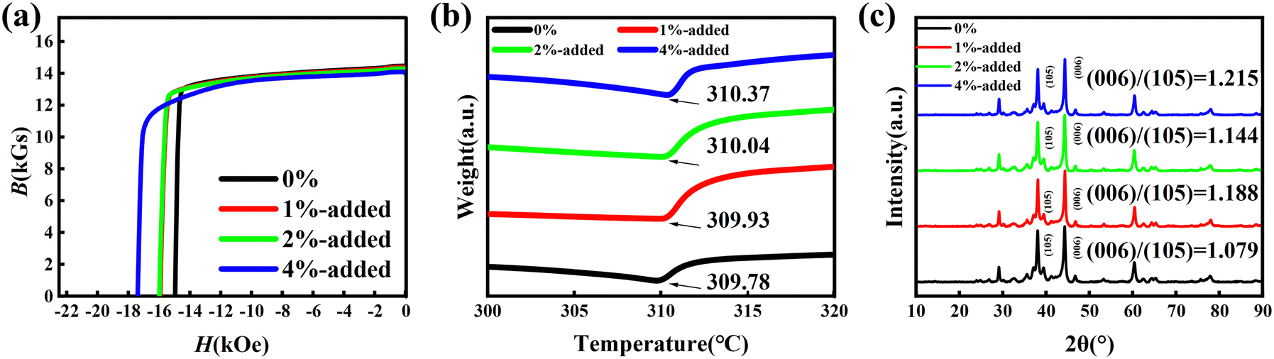
The room-temperature demagnetization curves of the original magnets and the magnets restructured with the Nd–Fe–Ga alloy are shown in Fig. 1a. The magnetic performance results of the studied magnets are also summarized in Table 1. The coercivities of the original magnet and magnets with Nd–Fe–Ga addition of 1%, 2%, and 4% are 14.96 kOe, 15.93 kOe, 15.99 kOe and 17.39 kOe, respectively. However, remanence Br decreases for magnets doped with 4% Nd–Fe–Ga alloy, and the slight decrease in remanence also results in a decrease in (BH)max. The reduction in Br may be due to the increase in additional GBPs (later shown to be the Nd6Fe13Ga phase), which are non-ferromagnetic or weak ferromagnetic and have a magnetic diluting effect on the magnetic properties.32Fig. 1b shows the TGA curves of the initial magnet and the Nd–Fe–Ga-added magnets. The Curie temperature of the magnet produces a slight enhancement with the Nd–Fe–Ga addition. The Curie temperature decreases due to the replacement of Fe for Co in the matrix grains during the post-sintering annealing process.33 However, it has been reported that the addition of Ga element can improve the Curie temperature of Nd2Fe14B-based sintered magnets due to the diffusion of Ga atoms into 2:14:1 phases and the formed RE2Fe14−xGaxB phases.34,35 In the Nd2Fe14B system, the Curie temperature was determined by the strongest 3d–3d exchange interactions. Ga element is preferential to occupy the j2 sites of Fe, which would reduce the negative exchange interactions, leading to the increase of the Curie temperature.36Fig. 1c shows the XRD analysis of the Nd–Fe–B sintered magnets doped with Nd–Fe–Ga additives ranging from 0 to 4 wt%. All the magnets are mainly composed of 2:14:1 structures with good (00L) orientation. For the original magnets, the intensity ratio of the (006) and (105) peaks is 1.079. The intensity ratios of the (006) and (105) peaks are slightly increased to 1.188, 1.144, and 1.215 when the Nd–Fe–Ga addition increases to 1%, 2%, and 4%, respectively. The increased ratio of (006)/(105) by Nd–Fe–Ga addition means the optimized orientation of the 2:14:1 phase grains, leading to retention of high Br for the Nd–Fe–Ga-added magnets.37,38
 | ||
| Fig. 1 (a) Demagnetization curves of the original magnet (0%), 1 wt%, 2 wt% and 4 wt% Nd–Fe–Ga added magnets at room temperature. (b) TGA curves and (c) XRD patterns of the investigated magnets. | ||
| Sample | H cj/kOe | B r/kGs | (BH)max/MGOe |
|---|---|---|---|
| 0% | 14.96 | 14.47 | 49.36 |
| 1%-added | 15.93 | 14.40 | 48.94 |
| 2%-added | 15.99 | 14.30 | 48.46 |
| 4%-added | 17.39 | 14.09 | 47.37 |
Fig. 2 shows the corrosion properties of the investigated magnets. Fig. 2a shows the mass loss of the investigated magnets in an accelerated corrosion test (131 °C, 2.5 bar and 95% relative humid atmosphere) for every 24 h. After accelerated corrosion for 24 h, the mass loss for the original magnet is larger than those of the GB-reconstructed magnets. In addition, the mass loss difference increases with the time of accelerated corrosion. For the original magnet, the mass loss decreases to 5.9 mg cm−2 for 120 h. However, for magnets with different Nd–Fe–Ga additions after grain boundary reconstruction, their mass losses are 4.1 mg cm−2, 3.9 mg cm−2 and 3.6 mg cm−2, respectively. Fig. 2b shows the Tafel curves measured in an aqueous solution of 3.5 wt% NaCl. The corresponding corrosion potentials Ecorr and corrosion current densities icorr calculated by the extrapolation of the Tafel slope are summarized in Table 2. Compared with the original magnet, the Ecorr value of the 4 wt% Nd–Fe–Ga-reconstructed magnets slightly improves from −0.802 V to −0.789 V. In addition, icorr is also reduced from 2.953 μA cm−2 for the original magnets to 2.152 μA cm−2 for the 4 wt% Nd–Fe–Ga-added magnets. Fig. 2c–f show the Nyquist plots and the corresponding equivalent circuit model to quantitatively evaluate the corrosion resistance in the NaCl solution.39 The enlargement of the impedance ring also suggests that the magnets have enhanced corrosion resistance as a result of the Nd–Fe–Ga GB reconstruction. In the circuit, Rs represents the electrolyte resistance, while CPE1 and R1 correspond to the capacitance and the electron transfer resistance in the oxide film of the electrode, respectively. CPE2 and R2 represent the double-layer capacitance and charge transfer resistance of the RE-rich phase, and CPE3 and R3 show the double-layer capacitance and charge transfer resistance of the Nd6Fe13Ga phase, respectively. The fitted impedance parameters obtained from the equivalent circuits are also summarized in Table 2. The magnets with the Nd–Fe–Ga addition show a larger R1 value than that of the original magnet. The decreasing R2 value is due to the reduction of RE-rich phase after Nd–Fe–Ga reconstruction. In the Nd–Fe–Ga reconstruction, the R3 values show a sustaining increase. Especially for the 4 wt% Nd–Fe–Ga-added magnet, the R3 value increases to 1480 Ω. Apparently, these results demonstrate that Nd–Fe–Ga GB addition effectively improves the corrosion resistance.
 | ||
| Fig. 2 (a) Mass loss curves for the investigated magnets. (b) Potentiokinetic polarization curves and (c) Nyquist diagrams for the investigated magnets in 3.5 wt% NaCl aqueous solutions. Nyquist curves and the fitting curves for the investigated magnets, (d) 0%, (e) 2 wt% and (f) 4 wt%. Insets show the fitted circuit, fitting data (solid lines) shows a good agreement with experimental data (dots). | ||
| Sample | E corr/V | i corr/μA cm−2 | R s/Ω cm2 | R 1/Ω cm2 | R 2/Ω cm2 | R 3/Ω cm2 | CPE1/[(F cm−2)/n] | CPE2/[(F cm−2)/n] | CPE3/[(F cm−2)/n] |
|---|---|---|---|---|---|---|---|---|---|
| 0% | −0.802 | 295.3 | 6.7 | 55 | 1232 | — | 6.7 × 10⁻⁴/0.84 | 9.1 × 10⁻⁴/0.69 | — |
| 1%-added | −0.796 | 236.2 | 6.2 | 600 | 667 | 120 | 3.5 × 10⁻⁴/0.76 | 5.7 × 10⁻⁴/0.99 | 9.1 × 10⁻⁴/1.45 |
| 2%-added | −0.794 | 240.5 | 7.0 | 446 | 359 | 736 | 4.0 × 10⁻⁴/0.73 | 1.9 × 10⁻³/1.54 | 3.4 × 10⁻⁴/1.11 |
| 4%-added | −0.789 | 215.2 | 8.9 | 447 | 243 | 1480 | 3.7 × 10⁻⁴/0.94 | 3.0 × 10⁻⁴/0.73 | 5.1 × 10⁻⁴/0.88 |
To gain further insights into the impact of the Nd–Fe–Ga addition on the magnetic performance and corrosion resistance of the magnets, a detailed analysis was performed to examine the microstructure evolution and elemental distribution variations in the magnets with varying levels of Nd–Fe–Ga addition. This analysis employed scanning electron microscopy (SEM) and electron probe microanalysis (EPMA) characterization techniques, as illustrated in Fig. 3. The microstructure of the Nd–Fe–B magnets has a decisive influence on the magnetic properties, especially the coercivity. The back-scattering SEM (BSE-SEM) images in Fig. 3 show the microstructural morphology of the Nd–Fe–B sintered magnets with different Nd–Fe–Ga additions. Among them, the dark gray region is the 2:14:1 main phase grain, and the white region refers to the Nd-rich phase. Besides, the well-defined gray-white region is Nd6Fe13Ga GBP, as marked by white arrows. For the original magnet, as illustrated in Fig. 3a, the GBs between the two 2:14:1 phase grains are discontinuous and fuzzy, and the adjacent Nd2Fe14B grains are in direct contact. Due to the absence of good magnetic isolation GBs, during the demagnetization process, this direct contact of the 2:14:1 phase grains facilitates the expansion of the demagnetized domains, which leads to the low coercivity.40 For the Nd–Fe–Ga-added magnets, the GBPs between the 2:14:1 phase grains become clear and continuous, and the adjacent 2:14:1 phase grains begin to be separated by light-gray grain boundaries. It demonstrates the weak exchange coupling between the adjacent 2:14:1 phase grains and is conducive to coercivity enhancement.40 It should be noted that the gradual increase in the volume fraction of the Nd6Fe13Ga phase with gray-white contrast for the Nd–Fe–Ga-added magnets can be detected, which is mainly distributed in the triple-junction region.
 | ||
| Fig. 3 BS-SEM and EPMA images of the original magnet (a), and the investigated magnets with 2 wt% (b) and 4 wt% (c) Nd–Fe–Ga addition. | ||
Furthermore, the varying elemental distribution is displayed in the EPMA results. As shown in Fig. 3a, for the original magnet, the Nd element, as well as the Cu element, is mainly enriched in the triple-junction region. After the Nd–Fe–Ga addition, as shown in Fig. 3b and c, the Cu-enriched region in the triple-junction region is obviously reduced. The Cu element is distributed along the continuous GBs, which can effectively reduce the defects of the 2:14:1 phase grains, improving the coercivity and corrosion resistance.21–23,41–44 Meanwhile, the difference in the Fe concentration in the GBs is also a phenomenon of interest. More regions of GBs with a less Fe content are observed in the Nd–Fe–Ga-added magnets than in the initial magnet, which is favorable for the formation of non-ferromagnetic continuous GBs, thus playing a role in the magnetic isolation of adjacent Nd2Fe14B grains.15,45 In addition, the Ga-enriched region also increases with the Nd–Fe–Ga addition. Note that the concentration of Nd elements in the Ga-enriched region is between the Nd-enriched phase and the 2:14:1 phase grains, confirming the formation of Nd6Fe13Ga GBP, which is consistent with a light-gray region in the BSE-SEM images.
In order to further confirm the generated Nd6Fe13Ga phase after 4 wt% Nd–Fe–Ga reconstruction, TEM characterizations were employed as shown in Fig. 4. Fig. 4a presents the morphology of a typical Nd–Fe–B magnet with the triple-junction GBP. From the SAED patterns in the inset of Fig. 4a, the Nd6Fe13Ga phase can be detected. The L-TEM results shown in Fig. 4b indicated that the magnetic domains of the adjacent 2:14:1 phase grains are apparently magnetic decoupled by the Nd6Fe13Ga phase and the continuous GBs. It means that the Nd6Fe13Ga phase indeed is non-ferromagnetic and is beneficial to coercivity enhancement.32 Obviously, the morphology of this GBP with an extension towards the two 2:14:1 phase grains is observed after the 4 wt% Nd–Fe–Ga reconstruction, as shown in Fig. 4c. The high-resolution TEM image and FFT result in Fig. 4d show that the crystal structure of this extended GB region with a width of ∼45 nm is still the Nd6Fe13Ga phase. The extension region of Nd6Fe13Ga effectively segregates the corner regions of the 2:14:1 phase grains, which can provide a better magnetic isolation.46 The elemental mapping results for the Nd6Fe13Ga phase present a low content of Fe and Cu elements, and a high content of Nd, Pr and Ga elements (Fig. 4g). Fig. 4e shows the continuous GB morphology along the Nd6Fe13Ga extension region. The continuous GB between the two 2:14:1 phase grains is clearly visible and is about 2.7 nm, which is slightly wider than the exchange coupling length of 2.1 nm.12 At the same time, the elemental distribution between the adjacent 2:14:1 phase grains in Fig. 4h and the line-scan results in Fig. 4f show an obvious continuous GB with a lower concentration of Fe than that in the 2:14:1 phase, and Pr, Nd, Cu and Ga elements enriched. It can be postulated that during the heat treatment process, due to the formation of the Nd6Fe13Ga phase at the triple-junction GBP, more RE and Cu are incorporated into the continuous GBs, resulting in the formation of RE-Cu-enriched continuous GBs. As reported in ref. 47, the formation energy of Nd6Fe13Cu is 0.73 eV, while the formation energy of Nd6Fe13Ga is around −4 eV. It can be inferred that the Cu, Ga-rich triple-junction GBP region in the sintered state tends to form the Ga-rich Nd6Fe13Ga phase during aging and Cu is forced to migrate to the continuous GBs. The above-mentioned results indicate that the continuous GB modified by the Nd6Fe13Ga phase is beneficial to achieve the magnetic decoupling effect of the adjacent 2:14:1 phase grains, leading to coercivity enhancement after Nd–Fe–Ga addition.32 Moreover, the Cu-rich continuous GBs with high corrosion potential can improve the anti-corrosion properties of the Nd–Fe–Ga-added magnets.22
 | ||
| Fig. 4 TEM characterizations for the 4 wt% Nd–Fe–Ga reconstructed magnet. Morphology of triple-junction GBP (a). Inset in (a) shows the SAED patterns of the triple-junction Nd6Fe13Ga GBP. (b) Spontaneous magnetic domain structure LTEM images (over-focused). (c) BF-TEM image of region A in (a). (d) HR-TEM and FFT images of the grain boundary extension region in (c). (e) HR-TEM image of the continuous GB at region B. (f) Line-scan results of the selected region in (e). EDS mapping results for grain boundary extension region (g) and continuous GB (h). | ||
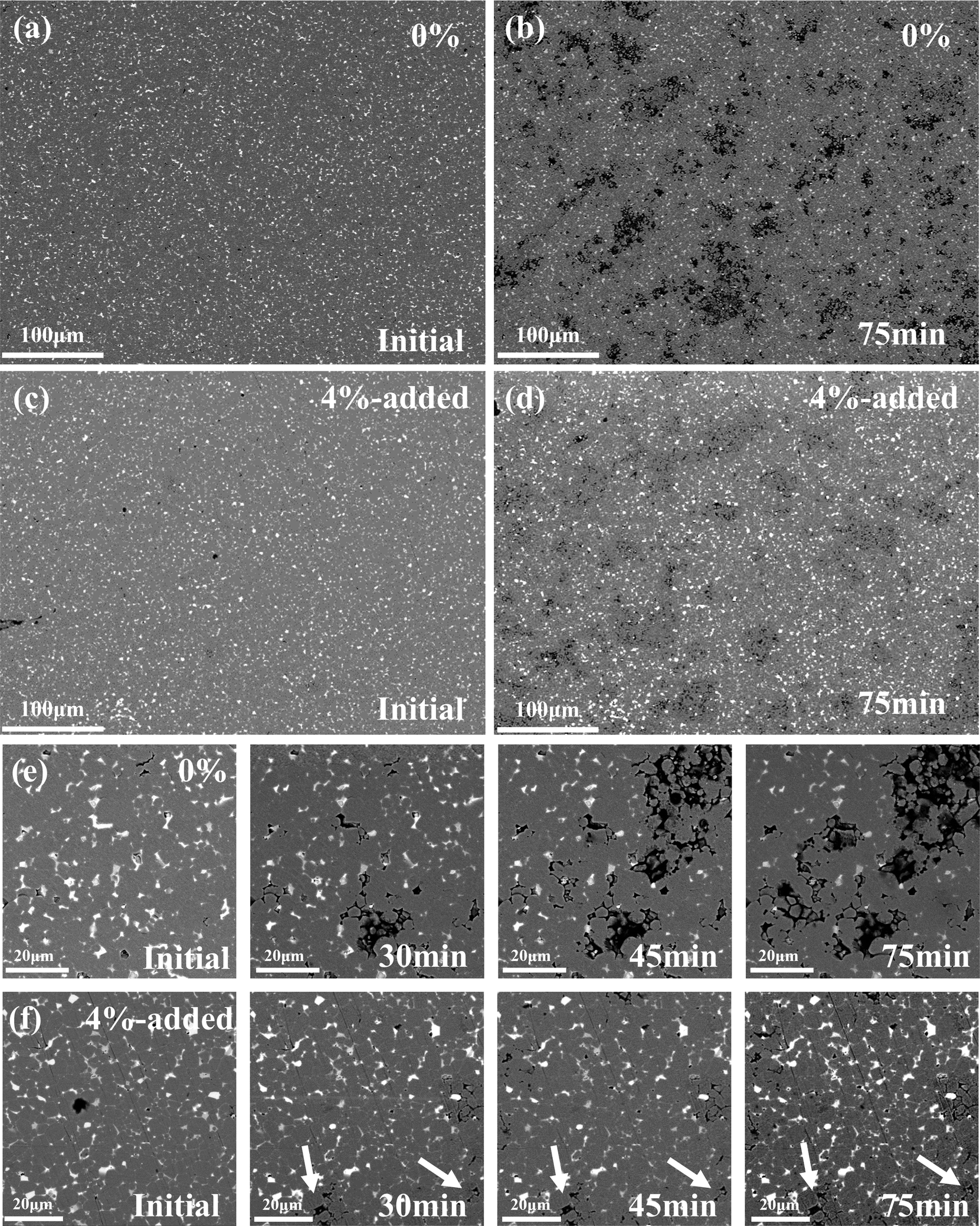
To provide a clearer representation of the influence of Nd–Fe–Ga GB reconstruction on corrosion, Fig. 5 illustrates the corrosion behavior of the original magnet and magnet with 4 wt% Nd–Fe–Ga addition after immersion in 3.5 wt% NaCl solution ranging from 0 to 75 min. As illustrated in Fig. 5a and b, compared to the initial state, numerous discernible corrosion areas with a clearly pronounced corrosion depth after corrosion from 30 min to 75 min appear on the of the original magnet. The formed extensive corrosion pits illustrate that, during the corrosion process, the exposed 2:14:1 phase grains increase the corrosion area, which further promotes corrosion expansion. However, for the magnet with 4 wt% Nd–Fe–Ga addition, small superficial corrosion areas can be observed after corrosion for 75 min, as shown in Fig. 5c and d. No obvious large corrosion pits are present. The in situ corrosion behavior has been observed under high-magnification SEM, as shown in Fig. 5e and f. Moreover, specific corrosion behavior at a high magnification for the Nd-rich phase and Nd6Fe13Ga phase in different samples are displayed in Fig. S2 (ESI†). After corrosion for about 30 min, several corrosion sites first appear in both the original magnet and the GB-restructured magnet in the RE-rich phase region. While for the original magnets, obvious corrosion defects have been distinctly formed. Not only that, upon extending the corrosion time, the corrosion area of the original magnet is also expanded significantly, and even local 2:14:1 phase grains have fallen off. However, for the Nd–Fe–Ga GB-restructured magnet, the corrosion sites are expanded slowly and even stagnated in the regions (as shown by the white arrows in Fig. 5f). These results indicate that the Nd–Fe–Ga GB reconstruction can slow down the corrosion process, significantly improving the corrosion resistance.
 | ||
| Fig. 5 Microstructure evolution of the in situ corrosion behavior of the original magnet (a) and (b) and the Nd–Fe–Ga-reconstructed magnet (c) and (d) after immersion in 3.5 wt% NaCl solution for 75 min. (e) and (f) Images of the in situ localized corrosion processes in the studied magnets ranging from 0 to 75 min. | ||
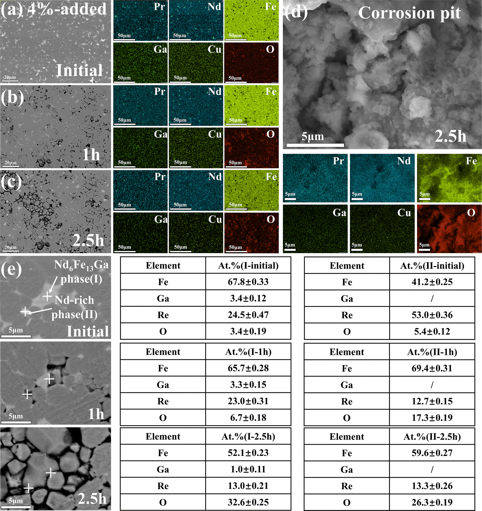
In order to study the changes in elements after corrosion and the speculation about the corrosion products, Fig. 6 shows the evolution of morphology and elemental distribution for the 4 wt% Nd–Fe–Ga-added magnet before and after corrosion in 3.5 wt% NaCl solution. As shown in Fig. 6a–c, O at the initial state is mainly concentrated in the Nd–O phase. As the corrosion time increases, corrosion craters appear on the surface of the magnet. With the corrosion time increased, obvious O enrichment can be observed in the corrosion pits. Fig. 6d shows the morphology and the elemental distribution of the corrosion pits at a high magnification. From the secondary electron SEM image (Fig. 6d), there are a large number of small and irregular corrosion products inside the corrosion pits. According to the EDS analysis, the corrosion products tend to exist in the form of O-rich phase. Moreover, the elemental distributions of Re, Fe, O, Cu and Ga are inhomogeneous, which illustrates that the corrosion products are complex due to the multi-phase structure in the Nd–Fe–B sintered magnet. Generally, the corrosion products of the Nd–Fe–B magnet are Fe3+, Nd3+ and oxygen-containing products.48,49 Here, we focus on the microstructure evolution and the elemental changes of the Nd6Fe13Ga phase and Nd-rich phase during the corrosion process (three consecutive tests were performed at each calibrated position during the experiment), as shown in Fig. 6e. For the Nd-rich phase, it can be seen that the Re content has significantly decreased from 53 at% to 12.7 at% and O increased from 5.4 at% to 17.3 at% after corrosion for 1 h. The increase in the Fe content may be due to exposure of underlying 2:14:1 phase grains after the rapid corrosion of the Nd-rich phase. After corrosion for 2.5 h, the change in Re content is not obvious. It can be presumed that after corrosion for 1 h, the Nd-rich phase has been completely corroded, and the decrease in Fe content and the increase in O show that the corrosion process has progressed to the underlying 2:14:1 phase grains, while, for the Nd6Fe13Ga phase, after corrosion for 1 h, the elemental changes are slow. The Fe content shows a slight decrease and the O content increases from 3.4 at% to 6.7 at%. After corrosion for 2.5 h, the O content rapidly increases to 32.6 at%, and the contents of Fe, Ga, and Re decrease to 52.1 at%, 1.0 at%, and 13.0 at%, respectively. Since the observed Nd6Fe13Ga phase has been completely corroded, there still remains 1.0 at% of Ga, which illustrates the Ga-containing corrosion products.
 | ||
| Fig. 6 Microstructure evolution of the in situ corrosion behavior of the 4 wt% Nd–Fe–Ga-reconstructed magnet and EDS mapping results after immersion in 3.5 wt% NaCl solution for (a) 0 h, (b) 1 h and (c) 2.5 h. (d) Microstructure image and EDS mapping results for the corrosion pit. (e) Changes in the in situ microscopic morphology during corrosion of Nd6Fe13Ga phases and Nd-rich phase, as well as quantitative analysis of elemental content. | ||
To uncover the corrosion mechanism for the GBP with different phase structures,50–55 the electrode potential differences between the 2:14:1 phase and the Nd-rich, the Nd6Fe13Ga phase as well as continuous GBs in the investigated magnets are conducted by KPFM results, as shown in Fig. 7a–d. The small light-grey area in Fig. 7a corresponds to the Nd6Fe13Ga phase generated from the small amount of Ga content (0.08 wt%) in the original magnet. From Fig. 7a–d, a large electrode potential difference of about 150 mV between the Nd-rich phase and the 2:14:1 phase was detected, which is much higher than that of about 50 mV between the Nd6Fe13Ga phase and the 2:14:1 phase. This reflects that the Nd-rich phase possesses a higher corrosion driving force than that of the Nd6Fe13Ga phase, and it is more likely to become the intergranular corrosion site in the corrosion environment. Moreover, for 0% magnet, the potential difference between the potential at the continuous grain boundary and the main phase is about 45 mV. However, the potential differences between the continuous grain boundary and the main phase are significantly reduced for the magnets which have undergone Nd–Fe–Ga GB reconstruction. This also reflects the improved corrosion resistance of these Cu-rich continuous GBs. Fig. 7e and f shows the changes in the in situ morphologies and electrode potential for 4 wt% Nd–Fe–Ga-constructed magnets immersed in 3.5 wt% NaCl solution for 4 h. Comparing the morphology during the corrosion process, it can be found that the Nd-rich phase is almost completely corroded after corrosion for 4 h, and the remaining GBP is mainly the Nd6Fe13Ga phase with grey contrast. Comparing the potential changes during the corrosion process, it can be found that the electrode potential difference between the Nd6Fe13Ga phase and the 2:14:1 phase after corrosion is significantly reduced from 50 mV to about 25 mV, which indicates that the corrosion driving force of the Nd6Fe13Ga phase is further reduced after the corrosion. On the contrary, in the corrosion cavities formed from the corroded Nd-rich phase, the electrode potential difference between the exposed GBPs and the 2:14:1 phase becomes negative, which may accelerate the corrosion process.22 In summary, the reasons for the increase in the corrosion resistance of Nd–Fe–Ga-reconstructed Nd–Fe–B sintered magnets can be ascribed to the low corrosion drive of the formed Nd6Fe13Ga phase, which does not tend to form corrosion sites throughout the corrosion process. As the volume fraction of the Nd6Fe13Ga phase increases, the possibility of spontaneous corrosion becomes lower, which promotes the anti-corrosive properties.
 | ||
| Fig. 7 Potential distribution of the grain boundary phases and continuous grain boundaries, the evolution of the morphologies and potential differences after corrosion in 3.5 wt% NaCl solution for the original magnet and the magnet after grain boundary reconstruction, (a) 0%, (b) 1 wt%, (c) 2 wt% and (d) 4 wt%. Changes in morphology and potential differences of 4 wt% Nd–Fe–Ga-added magnet before (e) and after (f) corrosion for 4 h. | ||
In order to further explain the corrosion behavior of these Nd–Fe–B sintered magnets, we adopted the first-principles calculations of the electron work function to verify the corrosion behavior. Nd–Fe–B magnets mainly contain two kinds of corrosion behaviors: chemical corrosion and electrochemical corrosion, of which electrochemical corrosion is the main one. In Nd–Fe–B sintered magnets, the two phases in direct contact undergo galvanic corrosion due to the existing potential difference. The region acting as the anode undergoes a severe anodic reaction and corrosion, while the cathodic region is protected in the electrochemical reaction.
The fundamental driving force of galvanic corrosion is the potential difference between the two phases due to the differences in the Fermi energy levels, and the following relationship exists between the potential difference and the electron work function:
| UA − UB = (WA − WB)/e | (1) |
| ϕ = Evacuum − EFermi | (2) |
Due to the existence of anisotropy of the crystals, different electronic work functions exist for different crystal faces. We chose the 2:14:1 phase, the Nd6Fe13Ga phase with the Nd-rich (Fcc) phase for the calculations at the common crystal faces observed in practice.
Fig. 8a shows the slab model of common crystal faces of the Nd-rich phase, Nd6Fe13Ga phase and 2:14:1 phase. Fig. 8b shows the first-principles calculated and plotted electrostatic potential energy curves for different crystal faces. The specific crystal faces and their corresponding calculated results are summarized in Table 3. It can be seen that the value of electron work function for the 2:14:1 phase is around 3.9 eV, the value for the Nd6Fe13Ga phase is about 3.3–3.5 eV, and for the fcc-structured Nd-rich phase, the value varies in a larger range of 2.7–3.2 eV. Thus, the fcc-structured Nd-rich phase has the lowest electron work function and tends to act as an anode region and corrode preferentially in the electrochemical corrosion process in direct contact with the Nd6Fe13Ga phase or 2:14:1 phase. As the electron work function value of the Nd6Fe13Ga phase is between those of the Nd-rich phase and 2:14:1 phase, it should act as a sacrificial anode in the corrosion process after the Nd-rich phase corrodes completely, which greatly slows down the corrosion process for the Nd–Fe–Ga-added magnet. The results of the above-mentioned calculations perfectly corroborate the phenomena observed in the actual experiments and provide strong theoretical support for the experimental results.
 | ||
| Fig. 8 Slab modeling of common crystal planes for the 2:14:1 phase, Nd6Fe13Ga phase, Nd-rich phase surface (a) and electron work function calculations of the corresponding crystal planes (b). | ||
| Phase | Crystal plane | E vacuum/eV | E Fermi/eV | ϕ/eV |
|---|---|---|---|---|
| Nd2Fe14B | (001) | 4.549 | 0.555 | 3.993 |
| (011) | 4.000 | 0.096 | 3.904 | |
| Nd6Fe13Ga | (100) | 3.464 | 0.129 | 3.334 |
| (012) | 3.034 | −0.484 | 3.518 | |
| Nd-rich(fcc) | (001) | 3.443 | 0.167 | 3.275 |
| (111) | 2.880 | 0.135 | 2.745 |
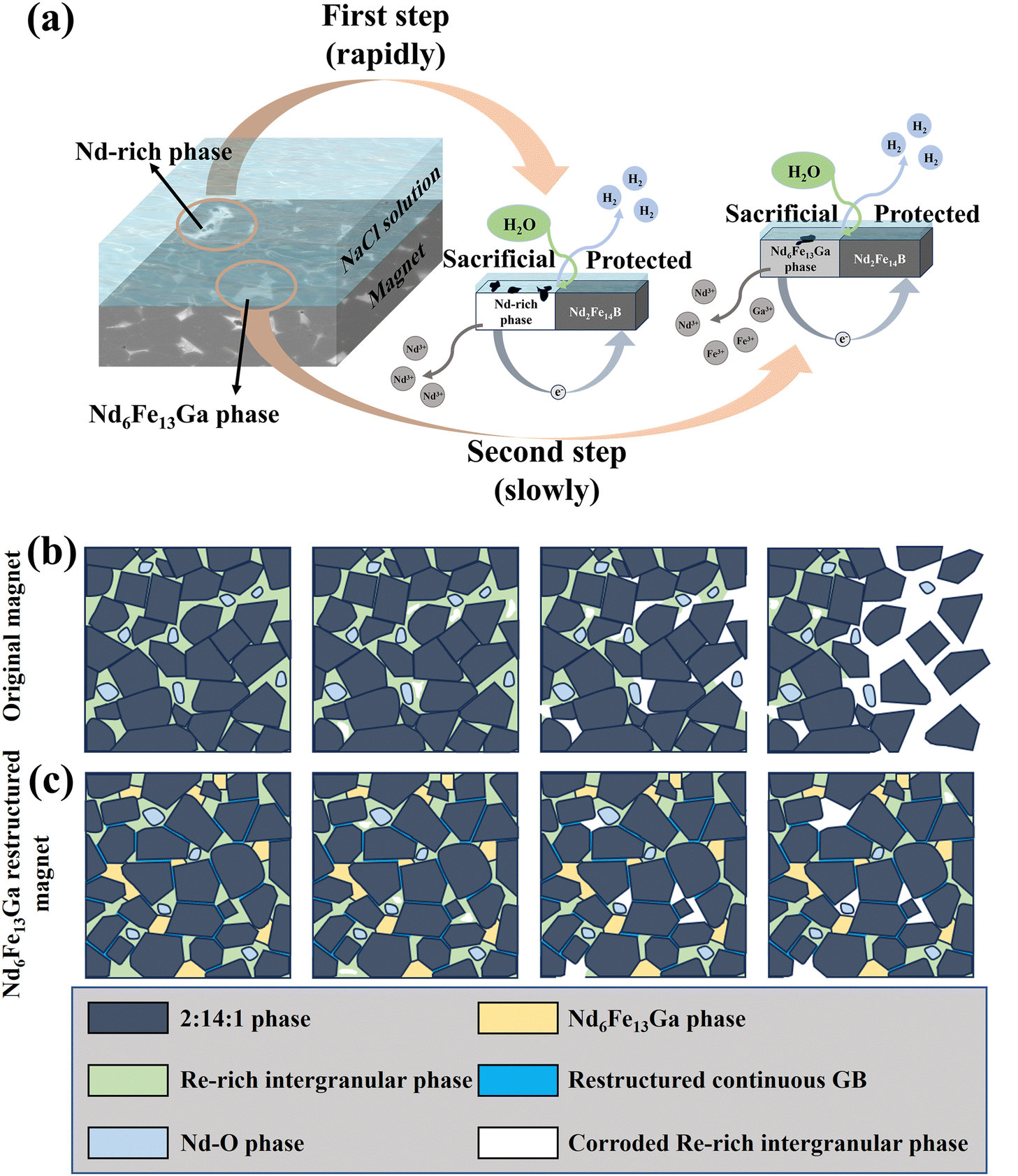
Based on the above-mentioned results, Fig. 9 shows the schematic model to explain the differences in the corrosion mechanisms of the original magnet and the Nd–Fe–Ga-reconstructed magnet. Fig. 9a shows the schematic image of the Nd–Fe–B sintered magnet during the corrosion process in aqueous NaCl solutions. Based on the experimental results (Fig. 5–7) and the conclusion of the first-principles calculations (Fig. 8), the Nd-rich phase is first corroded. Due to higher electric potential differences with the 2:14:1 phase (Fig. 7 and 8), the Nd-rich phase and the 2:14:1 phase constitute the primary cell corrosion, in which the Nd-rich phase acts as a sacrificial anode, losing electrons and being corroded rapidly. The second step is the corrosion of the Nd6Fe13Ga phase because of the lower electric potential difference with the 2:14:1 phase. Similarly, the Nd6Fe13Ga phase and the 2:14:1 phase constitute primary cell corrosion as a sacrificial anode that loses electrons. The corrosion products of the Nd6Fe13Ga phase refer to Fe3+, Nd3+, Ga3+ and oxygen-containing products.48,49Fig. 9b shows the typical corrosion behavior of the Nd–Fe–B sintered magnet. The Nd-rich phase is highly susceptible to the formation of corrosive nucleation sites under corrosive conditions. The corrosive region is prone to expand rapidly, resulting in the fall-off of the 2:14:1 phase grains. However, for the magnet after the Nd–Fe–Ga GB reconstruction (Fig. 9c), a large volume fraction of Nd6Fe13Ga GBPs was formed, and then the continuous GB with a high-potential Cu element was also optimized. Although the corrosion sites at the Nd-rich phase were also formed in the corrosive environment, the expansion of corrosion sites can be effectively hindered by the Nd6Fe13Ga phase and the optimized continuous GB with low corrosive driving force. The results indicated that the Nd6Fe13Ga phases generated by the Nd–Fe–Ga reconstruction can significantly impede the progress of corrosion and then improve the corrosion resistance.
 | ||
| Fig. 9 (a) A simulation of the peritectic corrosion process of the magnet in aqueous NaCl solution. A schematic model of the corrosion process for the original magnet (b) and the Nd–Fe–Ga-reconstructed magnet (c). | ||
4. Conclusions
In summary, the magnetic properties and corrosion resistance of the Nd–Fe–B sintered magnets have been concurrently improved by Nd–Fe–Ga reconstruction. The underlying mechanism of the optimized microstructure relative to the magnetic properties and corrosion resistance after the Nd–Fe–Ga addition has been concluded as follows:(1) The enhanced coercivity of Nd–Fe–B sintered magnet with Nd–Fe–Ga GB reconstruction is attributed to the formed Nd6Fe13Ga GBP and optimized continuous grain boundary.
(2) The formed Nd6Fe13Ga GBPs and modified grain boundaries are less susceptible to spontaneous corrosion on the magnet due to their high electrode potential, which can effectively impede the expansion of corrosion sites along the continuous GB, resulting in the improved corrosion resistance.
(3) The first-principles calculated electronic work functions of different phases in the Nd–Fe–B sintered magnet have verified that the Nd6Fe13Ga GBP is less susceptible to corrosion than the Nd-rich phase, providing strong theoretical support to the experimental results.
This work presented a viable methodology for achieving concurrent enhancement of corrosion resistance in Nd–Fe–B sintered magnets, elucidating the underlying mechanism.
Author contributions
Rui Shen: data curation, investigation, writing – original draft. Shuainan Xu: data curation, computation, investigation. Congyi wang: data curation, investigation. Enxiang Yang: data curation, investigation. Xiaolian Liu: conceptualization, methodology, data curation, writing – review & editing, resources, supervision. Song Fu: resources, data curation. Weiyang Jin: data curation, investigation. Yu Pan: resources, computation, formal analysis. Lizhong Zhao: formal analysis, resources. Pengfei Guan: computation. Xuefeng Zhang: writing – review & editing, resources, supervision.Data availability
Data will be made available on request.Conflicts of interest
There are no conflicts to declare.Acknowledgements
This work was supported by the National Natural Science Foundation of China (No. 52225312, 52371183 and 52101216), Natural Science Foundation of Zhejiang Province of China (No. LY24E010003).References
- M. Sagawa, S. Fujimura, N. Togawa, H. Yamamoto and Y. Matsuura, J. Appl. Phys., 1984, 55, 2083–2087 CrossRef CAS.
- K. Hono and H. Sepehri-Amin, Scr. Mater., 2012, 67, 530–535 CrossRef CAS.
- H. Kronmüller, K. D. Durst and M. Sagawa, J. Magn. Magn. Mater., 1988, 74, 291–302 CrossRef.
- S. Bance, J. Fischbacher and T. Schrefl, J. Appl. Phys., 2015, 117, 17A733 CrossRef.
- E. Yang, W. Jin, C. Man, X. Liu, S. Fu, L. Bo, S. Xu, L. Zhao, Z. Li, Z. Shi, M. Yu, L. Zhao and X. Zhang, J. Alloys Compd., 2023, 963, 171236 CrossRef CAS.
- J. He, Z. Yu, J. Cao, W. Song, K. Xu, W. Fan, H. Yu, X. Zhong, H. Mao, C. Mao and Z. Liu, J. Mater. Chem. C, 2022, 10, 2080–2088 RSC.
- J. Cui, M. Kramer, L. Zhou, F. Liu, A. Gabay, G. Hadjipanayis, B. Balasubramanian and D. Sellmyer, Acta Mater., 2018, 158, 118–137 CrossRef CAS.
- O. Gutfleisch, M. A. Willard, E. Brück, C. H. Chen, S. G. Sankar and J. P. Liu, Adv. Mater., 2010, 23, 821–842 CrossRef PubMed.
- S. Massari and M. Ruberti, Resour. Policy, 2013, 38, 36–43 CrossRef.
- K. P. Skokov and O. Gutfleisch, Scr. Mater., 2018, 154, 289–294 CrossRef CAS.
- T. T. Sasaki, T. Ohkubo, Y. Takada, T. Sato, A. Kato, Y. Kaneko and K. Hono, Scr. Mater., 2016, 113, 218–221 CrossRef CAS.
- X. D. Xu, T. T. Sasaki, J. N. Li, Z. J. Dong, H. Sepehri-Amin, T. H. Kim, T. Ohkubo, T. Schrefl and K. Hono, Acta Mater., 2018, 156, 146–157 CrossRef CAS.
- K. Niitsu, A. Sato, T. T. Sasaki, R. Sawada, Y. Cho, Y. Takada, T. Sato, Y. Kaneko, A. Kato, T. Ohkubo, D. Shindo, K. Hono and Y. Murakami, J. Alloys Compd., 2018, 752, 220–230 CrossRef CAS.
- M. Soderžnik, H. Sepehri-Amin, T. T. Sasaki, T. Ohkubo, Y. Takada, T. Sato, Y. Kaneko, A. Kato, T. Schrefl and K. Hono, Acta Mater., 2017, 135, 68–76 CrossRef.
- T. T. Sasaki, Y. Takada, H. Okazaki, T. Ohkubo, T. Nakamura, T. Sato, A. Kato, Y. Kaneko and K. Hono, J. Alloys Compd., 2019, 790, 750–759 CrossRef CAS.
- J. Li, X. Tang, H. Sepehri-Amin, T. T. Sasaki, T. Ohkubo and K. Hono, Acta Mater., 2020, 187, 66–72 CrossRef CAS.
- H. Bala, G. Pawlowska, S. Szymura and Y. M. Rabinovich, Br. Corros. J., 1998, 33, 37–41 CrossRef CAS.
- E. Isotahdon, E. Huttunen-Saarivirta, V. T. Kuokkala and M. Paju, Mater. Chem. Phys., 2012, 135, 762–771 CrossRef CAS.
- M. Rada, A. Gebert, I. Mazilu, K. Khlopkov, O. Gutfleisch, L. Schultz and W. Rodewald, J. Alloys Compd., 2006, 415, 111–120 CrossRef CAS.
- G. Yan, P. J. McGuiness, J. P. G. Farr and I. R. Harris, J. Alloys Compd., 2009, 478, 188–192 CrossRef CAS.
- J. Wang, G. Wang and D. Zeng, J. Magn. Magn. Mater., 2020, 503, 166639 CrossRef CAS.
- M. Pan, X. Liu, W. Jin, S. Fu, E. Yang, X. Liu, L. Zhao, X. Zhang and M. Yan, J. Magn. Magn. Mater., 2022, 550, 169109 CrossRef CAS.
- P. Zhang, T. Ma, L. Liang and M. Yan, Mater. Chem. Phys., 2014, 147, 982–986 CrossRef CAS.
- W. Mo, L. Zhang, Q. Liu, A. Shan, J. Wu and M. Komuro, Scr. Mater., 2008, 59, 179–182 CrossRef CAS.
- T. T. Sasaki, T. Ohkubo and K. Hono, Acta Mater., 2016, 115, 269–277 CrossRef CAS.
- P. Zhang, T. Ma, L. Liang, X. Liu, X. Wang, J. Jin, Y. Zhang and M. Yan, J. Magn. Magn. Mater., 2015, 379, 186–191 CrossRef CAS.
- L. Liu, H. Sepehri-Amin, T. Ohkubo, M. Yano, A. Kato, T. Shoji and K. Hono, J. Alloys Compd., 2016, 666, 432–439 CrossRef CAS.
- J. Wang, G. Wang and D. Zeng, J. Magn. Magn. Mater., 2020, 503, 166639 CrossRef CAS.
- G. Kresse and J. Furthmüller, Comput. Mater. Sci., 1996, 6, 15–50 CrossRef CAS.
- J. P. Perdew, J. A. Chevary, S. H. Vosko, K. A. Jackson, M. R. Pederson, D. J. Singh and C. Fiolhais, Phys. Rev. B: Condens. Matter Mater. Phys., 1992, 46, 6671–6687 CrossRef CAS PubMed.
- K. Momma and F. Izumi, J. Appl. Crystallogr., 2011, 44, 1272–1276 CrossRef CAS.
- J. Zhu, G. Ding, L. Jin, Z. Jin, B. Zheng, S. Guo, R. Chen and A. Yan, J. Rare Earths, 2022, 40, 924–929 CrossRef CAS.
- Q. Huang, Q. Jiang, J. Hu, S. U. Rehman, G. Fu, Q. Quan, J. Huang, D. Xu, D. Chen and Z. Zhong, J. Mater. Sci. Technol., 2022, 106, 236–242 CrossRef CAS.
- J. Hu, Z. Wang, Y. Wang, J. Zhao, X. Rao and N. Zhang, IEEE Trans. Magn., 1989, 25, 3429–3430 CrossRef CAS.
- M. Endoh, M. Tokunaga and H. Harada, IEEE Trans. Magn., 1987, 23, 2290–2292 CrossRef.
- S. Pan, G. Li, X. Yue, G. Fan and J. Ping, Rare Earth Soc., 1989, 8, 89 Search PubMed.
- X. Li, J. Li, K. Xu, Z. Wang, Y. Bian, Y. Shao, C. Hu and J. Ni, J. Rare Earths, 2022, 40, 930–936 CrossRef CAS.
- R. Lai, R. Chen, W. Yin, X. Tang, Z. Wang, C. Jin, D. Lee and A. Yan, J. Alloys Compd., 2017, 724, 275–279 CrossRef CAS.
- E. Isotahdon, E. Huttunen-Saarivirta, S. Heinonen, V. T. Kuokkala and M. Paju, J. Alloys Compd., 2015, 626, 349–359 CrossRef CAS.
- H. Kronmüller, Phys. Status Solidi B, 1987, 144, 385–396 CrossRef.
- Q. Huang, Q. Jiang, Y. Shi, S. Ur Rehman, D. Shi, G. Fu, Z. Li, D. Xu, D. Chen and Z. Zhong, J. Magn. Magn. Mater., 2022, 552, 169242 CrossRef CAS.
- K. Zhong, D. Shi and Z. Liu, J. Magn. Magn. Mater., 2023, 581, 170963 Search PubMed.
- M. Matsuura, S. Sugimoto, T. Fukada, R. Goto and N. Tezuka, J. Phys.: Conf. Ser., 2010, 200, 082019 CrossRef.
- J. Fidler, C. Groiss and M. Tokunaga, IEEE Trans. Magn., 1990, 26, 1948–1950 CrossRef CAS.
- G. Ding, S. Guo, L. Chen, J. Di, J. Song, R. Chen, D. Lee and A. Yan, J. Alloys Compd., 2018, 735, 795–801 CrossRef CAS.
- S. Xu, W. Jin, Z. Zhang, E. Yang, X. Liu, S. Fu, R. Shen, Z. Li, L. Zhao and X. Zhang, J. Alloys Compd., 2024, 973, 172893 CrossRef CAS.
- R.-Q. Liu, W.-T. Guo, S. Zhang, G. Fu, Q. Huang, Y. Zheng, S. Chen, J.-M. Zhang and Z. Huang, J. Magn. Magn. Mater., 2023, 587, 171242 CrossRef CAS.
- Y. Li, H. E. Evans, I. R. Harris and I. P. Jones, Oxid. Met., 2003, 59, 167–182 CrossRef CAS.
- C. J. Willman and K. S. V. L. Narasimhan, J. Appl. Phys., 1987, 61, 3766–3768 CrossRef CAS.
- X. G. Cui, M. Yan, T. Y. Ma and L. Q. Yu, Phys. B, 2008, 403, 4182–4185 CrossRef CAS.
- A. A. El-Moneim, A. Gebert, M. Uhlemann, O. Gutfleisch and L. Schultz, Corros. Sci., 2002, 44, 1857–1874 CrossRef CAS.
- L. Liang, T. Ma, P. Zhang and M. Yan, J. Magn. Magn. Mater., 2015, 384, 133–137 CrossRef CAS.
- J. Ni, T. Ma and M. Yan, Mater. Lett., 2012, 75, 1–3 CrossRef CAS.
- B. Peng, J. Jin, Y. Liu, C. Lu, L. Li and M. Yan, Corros. Sci., 2020, 177, 108972 CrossRef CAS.
- C. Sun, W. Q. Liu, H. Sun, M. Yue, X. F. Yi and J. W. Chen, J. Mater. Sci. Technol., 2012, 28, 927–930 CrossRef CAS.
Footnote |
| † Electronic supplementary information (ESI) available. See DOI: https://doi.org/10.1039/d4tc04062g |
| This journal is © The Royal Society of Chemistry 2025 |