DOI:
10.1039/D5RA03559G
(Paper)
RSC Adv., 2025,
15, 22432-22448
Shock wave-driven phase transition of iron sulphide for enhanced photocatalytic application: a combined experimental and DFT approach†
Received
20th May 2025
, Accepted 25th June 2025
First published on 30th June 2025
Abstract
In the present investigation, we systematically investigate how acoustic shock waves induce a phase transition from FeS to α-Fe2O3 and how this transition influences the material's structural, morphological, optical, and photocatalytic properties. The findings from X-ray diffraction (XRD), scanning electron microscopy (SEM), ultraviolet differential reflectance spectroscopy (UV-DRS), and X-ray photoelectron spectroscopy (XPS) studies unequivocally demonstrate a complete phase transition from FeS to α-Fe2O3 at 600 shock pulses. The control sample has an uneven morphology. The material exhibits moderate morphological changes but maintains its fundamental FeS phase after 400 shock pulses. On the other hand, the material undergoes a notable structural and morphological change at 600 shock pulses, assuming a distinct needle-like shape that is suggestive of phase transition and improved crystallinity. UV-DRS analysis reveals an increase in optical reflectance and a noticeable blue shift in the energy band gap under 600-shock conditions, further supporting the formation of a new phase with altered electronic structure. Density Functional Theory (DFT) calculations further support these findings, revealing a reduction in the electronic density of states (DOS) near the Fermi level upon phase transition, indicative of the enhanced charge separation crucial for improved photocatalytic performance. As a result, for FeS subjected to 600 shock pulses, transition to α-Fe2O3 exhibits superior photocatalytic efficiency and reaction rates compared to the control and other shock-treated samples.
1. Introduction
The incredible versatility of phase transition in materials has led to a surge in studies in recent years, with researchers from all corners of the scientific spectrum looking for interesting materials.1 The intriguing journey of studying phase change reactions in materials is always yielding new information about crystal structures and their functions.2 We can gain valuable insight into and direct evidence of the mechanism by studying materials' behaviour during phase transitions when subjected to extreme conditions. This understanding could pave the way for developing materials for various applications.3 Likewise, because certain materials have the potential to contribute to astounding applications, these kinds of phase transition experiments carried out on materials have significant importance not only in the research area but also in the world of industrialization.4,5 Such study also offers a different approach to finding breakthrough materials for future use in industry.6 It is possible to induce phase transformation by heat treatment, processing of the material, and by altering the parameters during synthesis, such as chemical composition, oxidation, reduction, etc.7 An additional potential option is to induce modifications to materials by employing external factors, such as pressure, temperature, a magnetic field, an electric field, or epitaxial strain.8,9 Moreover, applying pressure is a great way to fine-tune electrical, magnetic, structural, and vibrational characteristics for practical and theoretical analysis.10 Implications of significant importance can be discovered across the whole field of physical research, including the biological sciences.11 As a result of high pressure, virtually all materials undergo a transformation into distinct phases, which alters material crystallographic structures.12 In light of the fact that the crystal structure plays a preponderant role in determining the qualities of materials and their performance, it is of the utmost importance to increase our understanding of their crystal structure.2 Since the molecular volume of high-pressure phases is low, subjecting materials to high pressure is a useful technique for obtaining phase transitions.13 Theoretically, the equivalence criteria of matching Gibbs energies determine individual phase boundaries. There is a noticeable discrepancy between the phase equilibrium lines and the real transformation line at the start of the experiments. Therefore, partial pressure transitions (PTs) to high-pressure phases take place at pressures greater than the equilibrium pressure.14 Considerable experimental research has been conducted over the course of many years to investigate the phase transition of a variety of materials under static and dynamic pressure conditions.15,16 Apart from contributing to the investigation of static high-pressure and high-temperature observations, dynamic shock-induced phase transition experiments carried out on materials might offer essential details for the scientific community to aid in the understanding of the behaviors of molecules and atoms.17,18 In recent years, dynamic shock-induced phase transition experiments have emerged as one of the most promising areas of scientific inquiry. Many fascinating findings have been achieved in environments of extreme pressure in the past few decades, all because of advancements in experimental methods and computer models.19–21 Sivakumar et al. investigated using dynamic shock wave to induce a switchable phase change in Li2SO4 samples, switching them from an amorphous-glassy-crystalline to an amorphous phase.22 Furthermore, sodium sulphate crystals with a switchable phase transition were synthesised and displayed to work under shock conditions. The pattern of phase transitions, where changing to the sequence of shock pulses is 0, 1, 2, 3, and 4.23 Shock impact studies can employ these kinds of observations to infer the thermal-kinetic and thermodynamic states. At the same time, it is fascinating to accomplish phase transitions of materials under shocked conditions, where the results are similar to those of static high-pressure studies. In contrast to traditional thermal or chemical synthesis techniques, shock waves provide an extremely quick and non-equilibrium way to create phase transitions, which frequently lead to metastable structures, increased defect densities, and improved surface reactivity, all without the need for harsh chemicals or time-consuming processing.24 Contributing to enhanced photocatalytic performance, these characteristics offer a new and energy-efficient method of material engineering.25 In this particular case, we have opted to investigate the crystallographic phase stability of iron sulphide (FeS) under a shock wave flow environment for photocatalytic application. Iron sulphides are minerals that exist naturally and may be found in a wide range of geological formations.26 Additionally, FeS has a narrow band gap, excellent adsorption characteristics, and a unique capacity to transport electrons.27 The initial finding of a high-pressure phase of FeS was made by Taylor and Mao.28 According to previous reports, FeS exists in five stable phases: troilite (with parameters a = 3af and c = 2cf), hexagonal phase (with parameters a = 2af and c = cf), NiAs type phase (with parameters a = af and c = cf), and high-pressure phase (which remains stable at pressures more than 7 GPa).29,30 Ming et al. analysed FeS in situ resistance and reported four anomalous alterations during compression, which is evidence that the phase transition of semiconductor-semimetal-metal occurs, and two of these happen at pressures of 4.7 GPa and 62.3 GPa.31 To the best of our knowledge, all high-pressure measurements carried out on FeS were on static conditions; studies on the dynamic pressure of FeS are difficult to find. Consequently, it is possible that FeS NPs present a considerable opportunity for use in a variety of applications with extreme conditions. Specifically, photocatalysts for the breakdown of harmful organic compounds are seeing a rise in the utilisation of metal chalcogenides. A major environmental concern is the utilisation of visible light to initiate thermodynamically undesirable processes to break down organic hazardous dyes. Chemical and structural changes can control the surface atomic coordination and structure, which in turn control the catalytic efficiency of FeS.32 Maji et al. reported that, when exposed to light, FeS NPs enhance photocatalytic activity through the catalytic breakdown of MB. Furthermore, it follows standard Michaelis–Menten kinetics and demonstrates exceptional catalytic efficiency.33 Tan et al. analysed the photoactivity of FeS/WS2 nanosheets; research findings demonstrate that the FeS/WS2 heterojunction outperforms a pure WS2 catalyst due to its promotion of charge separation, which in turn enhances photocatalytic activity.34 Dutta et al. investigated nanocrystalline FeS/FeSe and reported that, unlike FeSe NPs, the rate constants for dye degradation when exposed to FeS NPs are higher.35 While all prior studies on FeS NPs were carried out in static or ambient pressure conditions, this study discusses the morphological, structural, optical, and chemical properties of FeS subjected to dynamic shock waves. Additionally, photocatalytic dye degradation using MB dye tests was performed on the control and the shock wave-loaded FeS samples.
2. Experimental details
2.1 Synthesis procedure
The elemental source materials Fe (99.5%) and S (99.5%) were obtained from SRL (Sisco Research Laboratories Pvt. Ltd, India) and used for the milling process. Fe and S powders were added to the milling jar at a stoichiometric ratio of 1![[thin space (1/6-em)]](https://www.rsc.org/images/entities/char_2009.gif) :2, along with process control agent (PCA) toluene. Planetary milling was performed utilising the Fritch Pulversitte P-6 classical line, with a hardened steel milling jar with a tungsten carbide inner wall and a volume of 250 mL. The balls were made of tungsten carbide and had two different diameters/weights (10 mm/8 g and 15 mm/26.2 g). A ball-to-powder ratio (BPR) of 15:1 and a milling speed of 500 rpm were maintained for 24 hours of milling. For every one hour of run time, 10 minutes of pause time was given.36 Further, the 24-hour milled samples were subjected to shock wave treatment for phase transitions analysis.
:2, along with process control agent (PCA) toluene. Planetary milling was performed utilising the Fritch Pulversitte P-6 classical line, with a hardened steel milling jar with a tungsten carbide inner wall and a volume of 250 mL. The balls were made of tungsten carbide and had two different diameters/weights (10 mm/8 g and 15 mm/26.2 g). A ball-to-powder ratio (BPR) of 15:1 and a milling speed of 500 rpm were maintained for 24 hours of milling. For every one hour of run time, 10 minutes of pause time was given.36 Further, the 24-hour milled samples were subjected to shock wave treatment for phase transitions analysis.
2.2 Characterization details
The shock wave experiments were conducted using a Tabletop Reddy shock tube. Using a Rigaku X-ray diffractometer with a Bragg–Bretano focusing geometry and monochromatic CuKα radiation (λ = 1.5406 Å), powder X-ray diffraction (PXRD) patterns were collected throughout the experiment. A JASCO V-530 UV-vis spectrophotometer was utilised to carry out photocatalytic research as well as research on reflectance spectra. Sample morphology was examined using a scanning electron microscope (SEM, VEGA TESCAN 3 variant). X-ray photoelectron spectroscopy, also referred to as XPS, was carried out with the assistance of a Thermo ESCALAB 250.
2.3 Computation details
To characterise the relationship between core and valence electrons, density functional theory (DFT) calculations were carried out using the Vienna Ab initio Simulation Package (VASP) in the projector-augmented wave (PAW) method.37,38 The exchange–correlation energy was treated using the Perdew–Burke–Ernzerhof (PBE) functional in the generalised gradient approximation (GGA).39 The conjugate gradient approach was used to minimise the total energy for structural relaxation, with a force convergence criteria of 10−3 eV Å−1. Using a Monkhorst–Pack k-point grid and an energy cutoff of 600 eV for the plane-wave basis set, the Brillouin zone was sampled. For electronic occupation, 0.1 eV Gaussian smearing was used. The energy difference barrier of 10−6 eV per atom was reached via the electronic self-consistency cycle. To analyse the pressure-induced phase transition, the total energy as a function of volume was fitted to the universal equation of state (EOS). For band structure calculations, the irreducible part of the first Brillouin zone was sampled along high-symmetry k-points. The density of states (DOS) and electronic band structures were computed with a denser k-point mesh to ensure accurate electronic properties.
2.4 Photocatalytic degradation of methylene blue
The photocatalytic activity of shock wave-loaded FeS NPs was assessed in this study. The purpose of this study was to explore the degradation of Methylene Blue (MB) in an aqueous solution in the presence of sunlight.40,41 With the objective of achieving an ideal adsorption–desorption equilibrium amongst the solution containing the MB dye and the catalyst, 10 mg of FeS catalyst powder was dispersed in 100 mL of aqueous methylene blue (MB) solution with a dye concentration of 10 mg L−1. In order to eliminate pH-induced artifacts in dye degradation, the photocatalytic studies were carried out in neutral pH settings (∼7). Following that, the resulting solutions were exposed to sunlight, and specimens were collected at regular intervals of fifteen minutes to determine the absorbance at a wavelength of 665 nm of the substance being studied. As the length of the reaction progressed, the findings showed that there was a decrease in the concentration of dye in the solution itself. This finding suggests that the photocatalysts worked well in the degradation of MB in an aqueous solution when exposed to sunlight.42,43
2.5 Shock wave loading
The intricacies of the propagating shock created within the shock tube and the parameters required to generate a shockwave were better understood by means of the evaluation of the shock tube.44,45 There are three parts to it: the driver, the driven, and the diaphragm sections. With an interior diameter of 1.5 cm in the driver as well as driven sections, the tubes of the driver (48 cm) and driven (33 cm) parts are made of seamless steel. To generate shock waves, atmospheric air was utilised in the driver and driven parts as the working resource, as shown in Fig. 1. Through the diaphragm part, the driver and driven sections are separated. With the assistance of pneumatic cylinders, diaphragms were introduced into the area dedicated to the diaphragm. During the process of compressing the air from the atmosphere into the driver section, the diaphragm was breached at the critical pressure.46 This caused a shock wave to form, which then travelled along the driven tube and struck the FeS sample.
 |
| | Fig. 1 Schematic illustration of semi-automatic Reddy tube. | |
For the purpose of this experiment, a shock wave with a Mach number of 1.7 was used to repeatedly strike the test sample with 200, 400, and 600 shock pulses, maintaining a two-second interval between consecutive pulses. It is worth noting that the duration of each pulse (test time) is 2.5 milliseconds. The pressure generated in the current investigation was 0.59 MPa, and a transient temperature of 520 K was calculated using the standard Rankine–Hugoniot (R–H) relation.45 Both the control samples and the shock wave loaded samples were sent for analytical tests once the experiment involving shock wave loading had been completed.47
3. Results and discussion
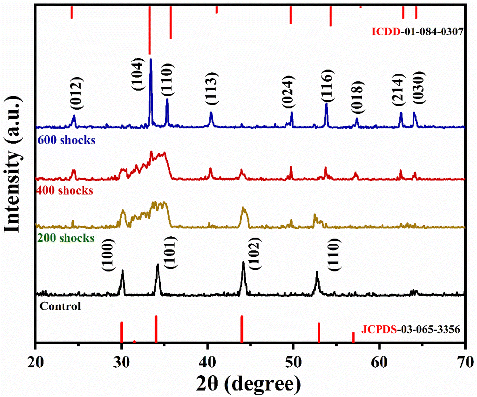
3.1 PXRD analysis
The PXRD has been measured for the control and various shocked samples, which exhibit a hexagonal crystal structure with space group P![[6 with combining macron]](https://www.rsc.org/images/entities/char_0036_0304.gif) 2c (190), in accordance with the existing literature.48 The lattice parameters for this material are a = 5.89 Å, b = 5.90 Å, and c = 11.42 Å.49 Fig. 2 illustrates the PXRD pattern of FeS as well as the phase transition that occurs at the 600-shock In accordance with the standard JCPDS card no. 89-6926, the peaks in the controlled FeS diffraction pattern that have been identified are (100), (101), (102), and (110).50 It has been noticed that there are significant variations in the context of diffraction peak intensity and peak position under shocked conditions. Under 200 shocks, the intensity of the existing peaks was reduced, and the diffraction peak (101) broadened. Further, moving on to 400 shock pulses, a few peaks vanished, and a new diffraction peak appeared. Additionally, increasing the shock pulses number to 600 revealed more peaks, such as (012), (104), (110), (113), (024), (116), (018), (214), and (030), strongly indicating the onset of a new α-Fe2O3 phase with rhombohedral structure. Using the JCPDS number 01-071-0053 as a reference, we found that all of the identified peaks were in good agreement with the typical hematite α-Fe2O3 (rhombohedral, R
2c (190), in accordance with the existing literature.48 The lattice parameters for this material are a = 5.89 Å, b = 5.90 Å, and c = 11.42 Å.49 Fig. 2 illustrates the PXRD pattern of FeS as well as the phase transition that occurs at the 600-shock In accordance with the standard JCPDS card no. 89-6926, the peaks in the controlled FeS diffraction pattern that have been identified are (100), (101), (102), and (110).50 It has been noticed that there are significant variations in the context of diffraction peak intensity and peak position under shocked conditions. Under 200 shocks, the intensity of the existing peaks was reduced, and the diffraction peak (101) broadened. Further, moving on to 400 shock pulses, a few peaks vanished, and a new diffraction peak appeared. Additionally, increasing the shock pulses number to 600 revealed more peaks, such as (012), (104), (110), (113), (024), (116), (018), (214), and (030), strongly indicating the onset of a new α-Fe2O3 phase with rhombohedral structure. Using the JCPDS number 01-071-0053 as a reference, we found that all of the identified peaks were in good agreement with the typical hematite α-Fe2O3 (rhombohedral, R![[3 with combining macron]](https://www.rsc.org/images/entities/char_0033_0304.gif) c) (167).51 It is common for FeS to have a hexagonal crystal shape in its initial form. Troilite is a mineral composed of iron (Fe) and sulphur (S) atoms organised in a precise pattern within a lattice.52
c) (167).51 It is common for FeS to have a hexagonal crystal shape in its initial form. Troilite is a mineral composed of iron (Fe) and sulphur (S) atoms organised in a precise pattern within a lattice.52
 |
| | Fig. 2 XRD pattern of control, 200, 400 and 600-shocked FeS sample. | |
The acoustic shock pulse deforms the FeS lattice by creating a high-pressure and temperature environment upon impact. This pressure causes oxygen atoms from the surface to enter the FeS lattice. Once inside the lattice, the oxygen atoms react with sulphur atoms because the oxygen has a higher electronegativity (3.44) than those of sulphur (2.58) and iron (1.83). Because of oxygen's stronger electronegativity, it is more likely to form sulphur–oxygen bonds than iron–sulphur bonds. Therefore, sulphur dioxide (SO2) gas is produced and released. At the same time, iron oxides are formed as a result of the reaction between oxygen and iron atoms (see Fig. 3).
 |
| | Fig. 3 Schematic representation of FeS nanoparticles undergoing structural transformation under shock wave treatment. The inset shows atomic-level rearrangement illustrating the replacement of S by O and the formation of Fe–O bonding. | |
The formation reaction is given below
| | |
4FeS + 7O2 → 2Fe2O3 + 4SO2
| (1) |
Each time an α-Fe2O3 molecule forms, two SO2 molecules are generated and escape from the lattice, creating vacancies. These empty spaces allow more oxygen atoms to penetrate the lattice, facilitated by the material being in a molten state. Additionally, the shock pulse generates high pressure, drastically reducing the activation energy required for these processes.
As a result, the peak broadened and decreased intensity occurs, as seen in Fig. 2. Iron sulphide is represented by the chemical formula FeS; it combines S2− anions with Fe2+ cations. Octahedral coordination is a common feature of FeS crystal structures. The transition from FeS to α-Fe2O3 occurs along a pathway affected by the severe physical and chemical conditions when the material is subjected to a high dynamic pressure and temperature environment. Because of the compressive force of high dynamic pressure, the crystal lattice might undergo the above-mentioned adaptations. Iron undergoes an oxidation reaction, whereas the oxidation of iron results in the transition of oxidation state from Fe2+ in FeS to Fe3+. The rates of most chemical reactions, including oxidation, are known to increase as pressure and temperature increase. Whenever the temperature rises, the molecules of the reactants gain energy, which speeds up the process and causes more frequent collisions. Overcoming an activation energy barrier is probably involved in the oxidation of hexagonal FeS. This barrier may be more easily overcome under higher temperatures, which speed up the rate of oxidation. The formation of α-Fe2O3 is the result of a reaction between FeS and oxygen, which functions as an electron acceptor. Over the course of these processes, electron transfer takes place. The presence of electron acceptors makes it easier for electrons to travel around, which in turn increases the number of oxidation states of iron. Similarly, Li et al. investigated the phase transitions as well as reactions of non-oxidized alongside mackinawite (FeS) in hydrogen sulphide and helium gas. An intermediate phase, known as greigite (Fe3S4), can be formed through the reaction of FeS. In addition, greigite can undergo an exothermic reaction, which results in the formation of pyrite (FeS2), a process that emits heat. The complete process wherein pyrite is produced when electron acceptors are present.53 However, in the current investigation, there is no formation of an intermediate phase up to 600-shock pulses. The availability of electron acceptors, high pressure and temperature conditions are some of the overarching parameters that greatly influence the reaction pathways, which in turn cause the phase transformation of FeS into α-Fe2O3.
3.2 Morphological analysis
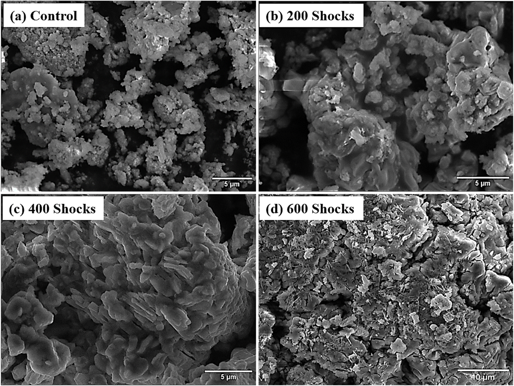
SEM analysis was undertaken to offer significantly persuasive evidence for the shock wave triggered phase transformation taking place in the FeS NPs, alongside the resulting microscopy images presented in Fig. 4. The figure shows that FeS is composed of tiny, irregularly shaped nanoparticles.54 As a result of the reduction in shape at the 200 shock condition, most of the spherical-shaped particles are transformed into coral reefs with petals. The picture that corresponds to this transformation can be found in Fig. 5. Following 300 shocks, the spherical shape is virtually eliminated; as a result, flowers with petal shapes are formed with nanoneedles (Fig. 5). A deep magnification view of the 300-shocked sample is shown in Fig. 5, which shows the nanoneedle formation. This is due to the dynamic recrystallisation induced by the shock waves.55 The oxidation rate and dynamic recrystallisation process, which are significantly related to the thermal parameters of FeS, are responsible for all of the morphological changes of FeS. In this particular scenario, recrystallisation holds the potential to result in the creation of hexagonal and rhombohedral crystal structures of FeS to α-Fe2O3, respectively. A significant amount of work has been put into influencing the shapes of these materials, which include microboxes,56 nanorods,57 nanoneedles,58 and hollow spheres59 during synthesis. Yet, the chemical techniques that are now available for altering the morphology of compounds are often either difficult to implement or not economically viable. For instance, J. Wang et al. investigated the synthesis of FeS/Fe2O3 by solvothermal oxidation technique. In this experiment, the FeS nanoparticles were introduced into the tube furnace and subjected to temperatures of 450 °C and 550 °C, at a heating rate of 1 °C per minute, for 10 hours. Finally, pristine Fe2O3 was produced when the temperature was lowered to the ambient temperature.60 Nevertheless, in our present case, within milliseconds, the FeS surface area was subjected to overheating effects as a consequence of transient temperature (520 K) and pressure (0.59 MPa). As a result, the oxidation phase α-Fe2O3 was seen in the material being examined. In addition, the majority of NPs incurred morphological distortions and alterations of their initial forms when subjected to shock pulse; only a relatively small percentage of the components maintained their initial physical characteristics. However, there have been a great number of shock wave studies that have considered tailoring the morphology in positive ways for synthesis or application purposes.55,61 In agreement with the findings of the XRD analysis, the phase transition from FeS to α-Fe2O3 exhibits a significant degree of resonance from a morphological perspective.
 |
| | Fig. 4 SEM images of (a) control, (b) 200-shocks, (c) 400-shocks, and (d) 600-shocks treated FeS sample. | |
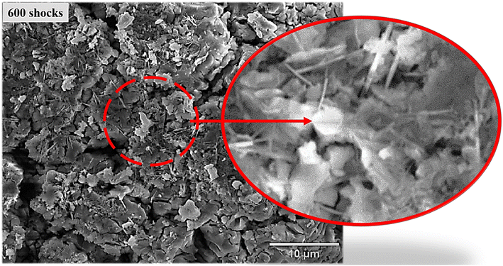 |
| | Fig. 5 Magnified view of the needle-like structure formed in the 600-shock flow exposure. | |
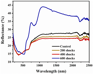
3.3 UV-DRS analysis
The UV-DRS spectra of the control and shock-wave loaded test material are shown in Fig. 6. There is a slight decrease in the absorbance percentage after 200 and 400 shock wave exposures. This is possibly because of the dislocations, surface defects, and distortions generated by the shock pulse, which in turn contribute to a reduction of optical absorbance.62 Furthermore, when the number of shock pulses is increased, a significant increase in the percentage of optical absorbance results, as can be seen in Fig. 6. One potential justification for the increase in absorbance at 600 shocks is the structural phase transition from hexagonal (FeS) to rhombohedral (α-Fe2O3) crystal structure, triggered by shock waves. Similarly, Sivakumar et al. utilised K2SO4 crystals and reported a red shift for the first shock; for the second shocks, the transmittance percentage returned to its initial position, indicating the reversible phase transition.63 Now, in the present case, it is evident that the 200 and 400 shock wave-treated XRD patterns were well distorted and deformed. With the further increase to 600 shock pulses, the FeS phase transformed into α-Fe2O3 with good crystalline peaks. UV-DRS results validate this by showing a slight drop in 200 and 400 reflectance % and a substantial increase in 600 optical reflectance %. Moreover, as the number of shock pulses increases, the XRD data show that increased lattice strain and the creation of defects decrease the crystalline nature. Similar to this, the UV reflectance spectra undergo a red shift following exposure to 200 and 400 shock waves. In agreement with the XRD results, this decreased optical absorbance signifies a reduced degree of crystalline nature and an increase of structural disorder.64
 |
| | Fig. 6 UV-DRS spectra of control and shocked FeS samples. | |
Taking into consideration that the optical reflectance values rely on the optical energy gap values, the band structure change might be validated based on the acquired data. Due to this particular rationale, the Tauc plot was plotted, as shown in Fig. 7(a–d), to identify the indirect optical band gap for control and shocked FeS samples.65 The calculated energy gap values are 3.7 eV, 3.8 eV, 3.8 eV, and 2.5 eV for the control, 200, 400 and 600 shocked samples, respectively. The drastic shift from 3.7 eV to 2.5 eV is due to the shock pulse-induced phase transformation from FeS to α-Fe2O3. In addition, through a discussion of pressure-induced electronic reconstruction, research into hexagonal FeS by Craco et al. provides insight into the basic principles of electronic transitions within materials under extreme conditions.66 The research also shows that electronic transitions in FeS at moderate pressures are caused by spin state shifts, which in turn cause orbitally selective Kondo quasiparticle electronic reconstruction at low energies. The complex interactions among electronic correlations and external stimuli like pressure are illustrated by the pressure-induced metal-insulator transition in FeS. Similarly, a wide bandgap is obtained as a consequence of these changes in electronic band structure and crystal-field splitting. Shock wave-induced phase transitions from FeS to α-Fe2O3 also include intricate electronic rearrangements driven by changes in the spin state and dynamic spectral weight transfer. Therefore, the band gap increased due to these changes in the material's electronic band structure.
 |
| | Fig. 7 Tauc plot for (a) control, (b) 200 shocks, (c) 400 shocks, and (d) 600 shock treated FeS specimens. | |
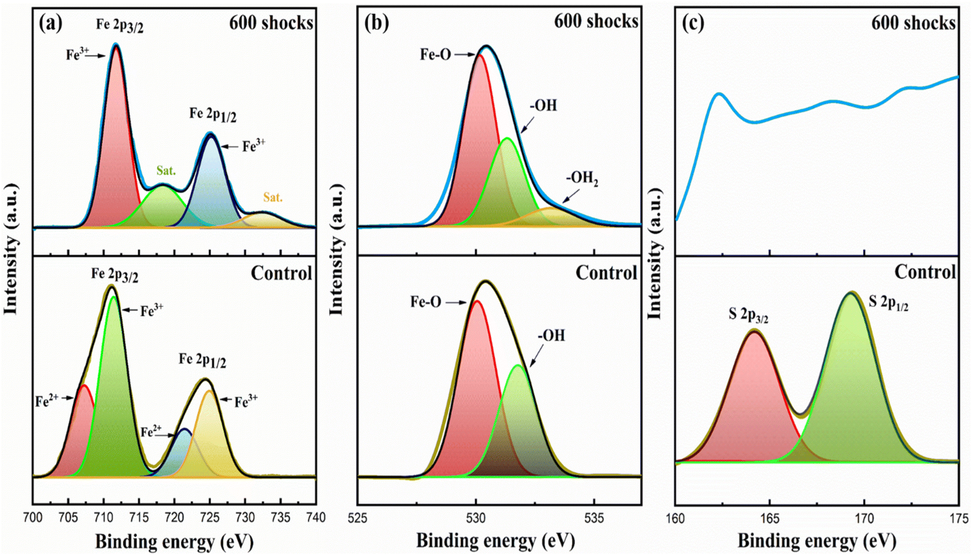
3.4 XPS analysis
X-ray photoelectron spectroscopy was carried out on the FeS sample to determine its surface chemical nature and the respective valence states of the Fe and S ions. The survey spectra of control and shock-loaded samples are depicted in Fig. 8. From the survey-scanning spectrum of control FeS, it can be observed that the primary component elements are Fe 2p, S 2p, and O 1s, representing FeS in its pure phase. It would be plausible to relate the peaks that were found at around 708.99 and 721.59 eV to Fe 2p3/2 and Fe 2p1/2, respectively, which indicates the presence of Fe2+ in FeS NPs.48 On the other hand, the peaks deconvoluted at 711.3 and 724.8 eV affirm the presence of Fe3+ in the control FeS, as shown in Fig. 9(a). In the case of the S 2p core level, the XPS spectra are displayed in Fig. 9(c). There are two signals at 164.5 and 169.2 eV that are associated with distinctive peaks S 2p3/2 and S 2p1/2, respectively. A significant peak associated with O 1s can be seen in Fig. 9(b); it is positioned at 530.2 eV. This peak can be ascribed to the formation of oxygen in FeS. After execution of the 600-shock pulse, the survey spectra reveal the presence of Fe and O, indicating the formation α-Fe2O3, as can be seen in Fig. 9(a–c). The peaks that were discovered at 711.4 and 724.7 eV, respectively, correspond to Fe 2p3/2 and Fe 2p1/2, which show the existence of Fe3+ in α-Fe2O3. This indicates the transition in oxidation states from Fe2+ to Fe3+, clearly validating the previous analysis that showed the formation of α-Fe2O3, as can be seen in Fig. 9(a).67 For additional confirmation, there are two satellite peaks found in Fe 2p around 718.5 eV and 732.5 eV, showing the phase transformation of α-Fe2O3.68 Fig. 9(c) displays the O 1s spectra of the 600 shock wave loaded FeS. The deconvolution peaks of the O 1s spectra are at 530.4 eV, and are attributed to crystal lattice oxygen; the peak at 531.8 eV corresponds to hydroxyl oxygen; that at 532.6 eV denotes adsorbed water.69 Consequently, the findings provide evidence that hydroxyl is present on the surface of the α-Fe2O3 particles. An additional faint peak developed at 533.4 eV when FeS was loaded with 600 shock pulses. This peak is attributed to the OIII component of surface oxygen atoms and may be seen at that energy level. In the control FeS nanoparticles, the atomic percentages remained at 14.7% for Fe 2p, 4.6% for S 2p, and 50.6% for O 1s. However, after incorporating shock waves, distinct atomic percentages were observed, with 8.78% for Fe 2p and 58.3% for O 1s. This clearly indicates the phase transformation of α-Fe2O3 and also indicates that, after the shock wave experiment, oxygen vacancies formed, which were the cause of the modifications that have been seen.
 |
| | Fig. 8 XPS spectra of control and 600 shock treated FeS samples. | |
 |
| | Fig. 9 XPS deconvolution for (a) Fe 2p, (b) O 1s, and (c) S 2p for control and 600 shock treated FeS samples. | |
3.5 DFT analysis
3.5.1 Phase stability and reaction energetics. To evaluate the oxidation pathways of FeS under varying conditions, Density Functional Theory (DFT) calculations were performed to determine the phase stability and reaction energetics of the oxidation products (refer to Fig. 10). The reaction energetics were analysed by computing the total energies of FeS, O2, α-Fe2O3, and FeSO4 to establish their relative thermodynamic stability. Upon exposure to oxygen, FeS undergoes oxidation, leading to the possible formation of α-Fe2O3 or FeSO4. The stability of these oxidation products is assessed through their respective reaction energies:
 |
| | Fig. 10 Reaction energy per reactant atom as a function of molar fraction of FeS in FeS–O2 system. | |
Reaction 1 (α-Fe2O3 formation):
| | |
0.692 O2 + 0.308 FeS → 0.103 Fe(SO4) + 0.051 Fe2O3
| (2) |
Calculated reaction energy (ΔE) = −320.1 kJ mol−1.
Reaction 2 (FeSO4 formation):
| | |
0.667 O2 + 0.333 FeS → 0.333 FeSO4
| (3) |
Calculated reaction energy (ΔE) = −326.0 kJ mol−1.
Both reactions exhibit strongly negative reaction energies, indicating that oxidation is thermodynamically favourable. However, the difference in ΔE between these two oxidation pathways is only 6 kJ mol−1, suggesting that both α-Fe2O3 and FeSO4 can coexist under specific conditions. The small energy gap implies that minor variations in external factors such as temperature, pressure, or reaction environment could shift the preferred oxidation pathway (Table 1).
Table 1 Analysis of FeS oxidation under different molar fractions of O2
| Molar fraction |
Reaction equation (normalized to reflect molar fraction) |
Erxn of eqn (kJ mol−1) |
| 0.000 |
O2 → O2 |
0 |
| 0.308 |
0.692 O2 + 0.308 FeS → 0.103 Fe2(SO4)3 + 0.051 Fe2O3 |
−320.1 |
| 0.333 |
0.667 O2 + 0.333 FeS → 0.333 FeSO4 |
−326.0 |
3.5.2 Energy–volume relationship and structural stability. The energy–volume (E–V) curves of FeS and its oxidation products provide further insights into phase stability. The computed E–V curves, plotted for multiple phases, show local minima corresponding to stable crystal structures. α-Fe2O3 and FeSO4 exhibit closely spaced local minima, indicating that their relative stability is highly dependent on external thermodynamic conditions, as shown in Fig. 11. The phase transition from FeS to α-Fe2O3 is associated with a noticeable volume reduction, which suggests densification of the material upon oxidation. The formation of FeSO4 exhibits a more gradual energy change with respect to volume, indicating that its structural stability is less sensitive to compression effects. From these observations, it is evident that shock wave compression, external pressure, and high-temperature conditions could influence the relative stability of α-Fe2O3, making phase selection tunable. This is particularly relevant for applications in which controlled phase formation is required, such as in photocatalysis.70
 |
| | Fig. 11 Energy vs. volume curves for different structural phases of FeS, with corresponding atomic structures overlaid. | |
3.5.3 Electronic structure and bonding analysis. To gain deeper insight into the oxidation mechanisms and electronic behaviour of FeS and its oxidation products, we performed Density of States (DOS) calculations and charge density analysis. The oxidation process significantly alters the electronic structure, which in turn affects material properties such as conductivity, bandgap, and photocatalytic performance.
3.5.3.1 DOS analysis. The electronic structures of the parent FeS and the Fe2O3 (corresponding to 600 shocks) were investigated through spin-polarized projected density of states (PDOS) calculations, shown in Fig. 12(a and b).
 |
| | Fig. 12 Projected density of states for (a) FeS and (b) α-Fe2O3. The contributions from FeS and α-Fe2O3 are shown, indicating hybridisation and electronic states near the Fermi level. | |
The Fermi level intersects the Fe 3d states, indicating metallic behaviour for pristine FeS. The finite density of states at the Fermi level confirms its conductivity, consistent with the known semimetallic nature of FeS.
3.5.3.1.2 α-Fe2O3.
For the shock-treated sample, which leads to the formation of α-Fe2O3, the PDOS shows clear signs of electronic structure modification. A noticeable band gap opens up at the Fermi level, and the DOS near the Fermi level significantly decreases compared to FeS, indicating a transition to semiconducting behaviour. The Fe 3d states are more localised and separated from the O 2p states, though moderate hybridisation still exists between −6 eV and −2 eV. The oxygen 2p states dominate the deeper valence band region, while Fe 3d contributes closer to the conduction band edge. This suggests that under high-energy shock treatment (600 shocks), FeS undergoes significant oxidation, leading to the formation of α-Fe2O3 with reduced conductivity and modified magnetic and bonding characteristics.
3.5.3.2 Charge density and bonding characteristics. Charge density distribution maps were computed to visualise the bonding nature in FeS, Fe2O3, and FeSO4. The charge density plots show strong covalent bonding between Fe and S atoms, with significant charge accumulation along the Fe–S bonds. The charge transfer between Fe and S is indicative of the partial ionic character, but FeS remains largely metallic in nature. The oxidation process leads to stronger Fe–O ionic interactions as oxygen atoms withdraw electron density from Fe. The charge density maps exhibit localized charge accumulation around O atoms, confirming the increased ionicity in Fe2O3. The Fe atoms exhibit a high-spin state due to unpaired 3d electrons, which influences magnetic properties. The Fe–O bonding in FeSO4 is also highly ionic, with a homogeneous charge distribution, making FeSO4 structurally stable under different conditions. Compared to α-Fe2O3, FeSO4 exhibits weaker Fe–O bonding, which may impact its catalytic efficiency.
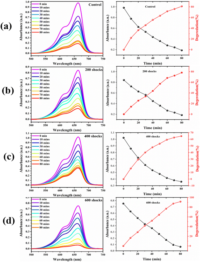
3.6 Photocatalytic study
It is important to note that crystallographically induced structural phase transitions, as well as variation in morphology and band gap of the shocked FeS samples, significantly influence the photocatalytic property, which includes the degradation efficiency.71,72 These parameters play significant roles in enhancing or diminishing the photocatalytic activity of materials, notably in processes such as the degradation of pollutants and the creation of hydrogen.73,74 There is a strong possibility that the catalytic property of the FeS nanoparticles might undergo a significant degree of transformation due to the remarkable morphological variations and the formation of a new phase under a 600-shock pulse. Fig. 13(a–d) shows the reflectance spectra of the control and shock-loaded FeS sample.| |
 | (4) |
 |
| | Fig. 13 Photocatalytic dye degradation of (a) control, (b) 200 shocks, (c) 400 shocks, and (d) 600 shock treated FeS samples. | |
Through the course of the experiment, the beginning absorbance, which was marked as A0, and the end readings, which were labelled as At, were recorded. The degrading efficiency estimates of the control, 200, 400, and 600 shock pulses were 78.4%, 77.1%, 64.7%, and 98.41%, according to eqn (2). The efficiency of the shock wave-treated FeS decreases for the 200 and 400 shock pulse samples, and dramatically, the efficiency increases for the 600 shock-treated FeS. The low efficiency obtained for the 200 and 400 shocked FeS samples is due to defects;75 these defects serve as recombination centres for electrons and hydrogen ions. When FeS undergoes deformations such as stress and strain due to shock impulsion, this in turn affects the photocatalytic property. Jarvin et al. investigated the photocatalytic activity of SnO2 NPs under the effects of shock waves and reported that the photocatalytic efficiency of the parent SnO2 NPs in the degradation of VB dye is greater than that of the shock-treated samples. Further, the degradation efficiency decreased due to the variations in the bond length, as well as other factors such as stress and strain.75 Interestingly, for 600 shock wave-treated samples, the efficiency increased to 91.2%. This increased efficiency is due to the phase transformation from FeS to α-Fe2O3 induced by the shock waves. Moreover, the enhancement is due to the following factors: when FeS undergoes a phase transition to α-Fe2O3, the change modifies the optical properties via changes in the material's energy gap. A narrow bandgap means that more visible light photons are absorbed by α-Fe2O3 than by FeS. This extended reflectance spectrum enables a more effective use of solar energy by improving the photocatalytic activity under exposure to visible light; conversely, the reduction in reflectance % in the 200 and 400 shocked samples is responsible for the lower efficiency rate. In contrast to the control and the 200- and 400-shock wave-treated FeS nanoparticles, the 600-shock-treated FeS sample exhibits superior photodegradation activity. To quantify this performance, a pseudo-first-order kinetic model was applied to evaluate the degradation rate of MB dye. The corresponding rate constants, derived from linear fits of ln(C0/C) versus time (as shown in Fig. 14(a and b)), are as follows: control: 0.063 × 10⁻² min−1, 200 shocks: 0.053 × 10⁻² min−1, 400 shocks: 0.041 × 10⁻² min−1, 600 shocks: 0.078 × 10⁻² min−1, these results Fig. 14(a and b) clearly indicate that the 600-shock wave-treated FeS sample demonstrates the highest photocatalytic activity, as reflected by the highest rate constant.76 Table 2 provides a clear visual representation of the current research findings and of the photodegradation efficiency found in this study in comparison to values in previous research works. It is possible to tailor the structural, optical, morphological, and photocatalytic characteristics of FeS by altering the number of shocks. This leads us to a potential versatile material for accelerating wastewater degradation in the textile sector.
 |
| | Fig. 14 Catalytic performance (a and b) pseudo-first-order kinetics, (c) efficiency histogram, (d) band gap and efficiency comparison for control and shocked FeS samples. | |
Table 2 FeS photocatalytic performance comparison
| Material |
Dye |
Catalyst dosage |
Dye conc. |
Solution pH |
Source |
Performance (%) |
Ref. |
| Ag–Fe2O3 |
MB |
0.4 g L−1 |
10 mg |
7 |
Sunlight |
96.33 |
77 |
| α-Fe2O3 |
MB |
1 g L−1 |
3.2 mg |
∼3 |
UV |
65 |
78 |
| α-Fe2O3 NPs |
MB |
0.4 g L−1 |
10 mg |
6.5 |
Sunlight |
78.68 |
79 |
| α-Fe2O3 NPs |
RY |
0.4 g L−1 |
10 mg |
∼6.5 |
UV |
75 |
80 |
| Fe2O3/TiO2 |
MB |
0.3 g L−1 |
10 mg |
6.5 |
UV |
97 |
81 |
| 600 Shock treated α-Fe2O3 |
MB |
0.1 g L−1 |
10 mg |
∼7 |
Sunlight |
91.2 |
Present study |
3.6.1 Possible photocatalytic mechanism. The possible mechanism for the enhanced photocatalytic activity is shown in Fig. 15.
 |
| | Fig. 15 Schematic representation of the dye depredation mechanism of control FeS and 600 shock-treated α-Fe2O3. | |
3.6.2 Initial shock exposure (200 and 400 shocks). Shock initialisation (200 and 400 shocks) causes nanoparticles to develop structural defects and dislocations at 200 and 400 shock wave-loaded conditions. Vacancies, interstitials, and dislocations are examples of defects that can serve as sites for non-radiative recombination of photogenerated electrons and holes. As a result of the existence of these defects and wider band gap, the chance of electron–hole recombination is increased, which in turn reduces the number of charge carriers that are accessible for photocatalytic processes. Due to the fact that fewer electrons and holes are involved in producing reactive species that eliminate pollutants, the effectiveness of photocatalytic degradation drops.
3.6.3 600 Shock pulse exposure. At 600 shocks, there is an apparent shift in the phase of the α-Fe2O3 nanoparticles, which potentially indicates that they have become crystalline and have a better crystal structure. Crystalline enhancements lessen the number of recombination centres caused by defects and dislocations.82 In situations in which there are fewer recombination centres, the rate at which photogenerated electron–hole pairs recombine is likely to decrease, increasing the visible light reflectance. More electron–hole pairs are produced by this increase in light reflectance. As a result, the photocatalytic degradation is improved in the 600-shocked FeS sample.
4. Conclusion
Our study effectively deduced the phase transformation of FeS to α-Fe2O3 induced by acoustical shock waves. The oxidation of FeS with oxygen from the atmosphere, which takes place during 600 shock pulses, is responsible for the transition of troilite into the hematite crystal structure. XRD patterns prove that the α-Fe2O3 phase was formed under the 600-shock condition. Furthermore, the results obtained from SEM and UV-DRS fully concur with the XRD data. Interestingly, with a 600-shock pulse, a nanoneedle-like structure formed. Moreover, the XPS analysis validates the current research by confirming that sulphur ceased to exist in 600 shock-loading conditions. DFT-based electronic structure analysis confirms that oxidation transforms FeS from a metallic state to a semiconducting oxide (α-Fe2O3 or FeSO4) with altered band gaps and charge distributions. The ionic Fe–O bonding in both oxidation products stabilises their crystal structures, but α-Fe2O3 remains the more promising phase for photocatalytic applications due to its optimal electronic properties. Photocatalytic study provides a clear representation of the increase in degradation efficiency compared to the control, and the 200 and 400 shock treated samples. The reaction rate constants were 0.063 × 10⁻² min−1, 0.053 × 10⁻² min−1, 0.041 × 10⁻² min−1, and 0.078 × 10⁻² min−1. The efficiency significantly diminished when the number of shock pulses increased to 200 and 400 because of distortions and defects that occurred throughout the process. These defects served as recombination centres for e− and h+. Further, at 600 shock pulses, the efficiency increased to 91.2% due to the phase transformation. Therefore, shock wave-treated FeS can be utilised in photocatalytic applications in future.
Data availability
All the data used in the manuscript are within the manuscript.
Conflicts of interest
The authors declare that they have no conflicts of interest.
Acknowledgements
This work was supported by the National Research Foundation of Korea (NRF) grant funded by the Korea government (MSIT) (RS-2025-00557769).
References
- L. Zhang, Y. Wang, J. Lv and Y. Ma, Materials discovery at high pressures, Nat. Rev. Mater., 2017, 2, 17005, DOI:10.1038/natrevmats.2017.5.
- D. Errandonea, Pressure-Induced Phase Transformations, Crystals, 2020, 10, 595, DOI:10.3390/cryst10070595.
- F. Coppari, R. F. Smith, J. H. Eggert, J. Wang, J. R. Rygg, A. Lazicki, J. A. Hawreliak, G. W. Collins and T. S. Duffy, Experimental evidence for a phase transition in magnesium oxide at exoplanet pressures, Nat. Geosci., 2013, 6, 926–929, DOI:10.1038/ngeo1948.
- Z. Martins, M. C. Price, N. Goldman, M. A. Sephton and M. J. Burchell, Shock synthesis of amino acids from impacting cometary and icy planet surface analogues, Nat. Geosci., 2013, 6, 1045–1049, DOI:10.1038/ngeo1930.
- C. Chyba and C. Sagan, Endogenous production, exogenous delivery and impact-shock synthesis of organic molecules: an inventory for the origins of life, Nature, 1992, 355, 125–132, DOI:10.1038/355125a0.
- S. Nagar and P. K. Singh, A short review on the Industrial applications of phase change materials, IOP Conf. Ser.:Mater. Sci. Eng., 2021, 1116, 012006, DOI:10.1088/1757-899X/1116/1/012006.
- W. B. Holzapfel, Physics of solids under strong compression, Rep. Prog. Phys., 1996, 59, 29–90, DOI:10.1088/0034-4885/59/1/002.
- R. J. Hemley, Effects of High Pressure on Molecules, Annu. Rev. Phys. Chem., 2000, 51, 763–800, DOI:10.1146/annurev.physchem.51.1.763.
- J. V. Badding, High-Pressure Synthesis, Characterization, and Tuning of Solid State Materials, Annu. Rev. Mater. Sci., 1998, 28, 631–658, DOI:10.1146/annurev.matsci.28.1.631.
- H. Yu, F. Peng, H. Liang, S. Guan, L. Tan, Z. Xiong, X. Xiang, Q. Li, L. Lei and D. He, Pressure-Induced Structural Phase Transformation and Yield Strength of AlN, J. Phys. Chem. C, 2019, 123, 28437–28442, DOI:10.1021/acs.jpcc.9b07459.
- Z. P. Tang and Y. M. Gupta, Shock-induced phase transformation in cadmium sulfide dispersed in an elastomer, J. Appl. Phys., 1988, 64, 1827–1837, DOI:10.1063/1.341782.
- A. Jayaraman, Diamond anvil cell and high-pressure physical investigations, Rev. Mod. Phys., 1983, 55, 65–108, DOI:10.1103/RevModPhys.55.65.
- D. D. Dlott, Ultrafast Spectroscopy of Shock Waves in Molecular Materials, Annu. Rev. Phys. Chem., 1999, 50, 251–278, DOI:10.1146/annurev.physchem.50.1.251.
- V. I. Levitas, High pressure phase transformations revisited, J. Phys.:Condens. Matter, 2018, 30, 163001, DOI:10.1088/1361-648X/aab4b0.
- L. Dai, K. Liu, H. Li, L. Wu, H. Hu, Y. Zhuang, L. Yang, C. Pu and P. Liu, Pressure-induced irreversible metallization accompanying the phase transitions in Sb2S3, Phys. Rev. B, 2018, 97, 024103, DOI:10.1103/PhysRevB.97.024103.
- S. Surendhar, P. Sivaprakash, J. Jerries Infanta, R. Jagadeesh, S. A. Martin Britto Dhas, I. Kim and S. Arumugam, Enhancing the efficiency of gas sensing on perovskite BaTiO3 nanoparticles using dynamic shock wave flow environment, Ceram. Int., 2024, 50(13), 23710–23720, DOI:10.1016/j.ceramint.2024.04.094.
- S. Aswathappa, S. Suresh, S. Balachandar, D. Thirupathy, K. S. Jeyaperumal and M. Dhas, Effect of shock waves on thermophysical properties of ADP and KDP crystals, Opt. Laser Technol., 2019, 111, 284–289, DOI:10.1016/j.optlastec.2018.10.001.
- Z. Su, W. L. Shaw, Y.-R. Miao, S. You, D. D. Dlott and K. S. Suslick, Shock Wave Chemistry in a Metal-Organic Framework, J. Am. Chem. Soc., 2017, 139, 4619–4622, DOI:10.1021/jacs.6b12956.
- A. Sivakumar, S. S. J. Dhas, P. Sivaprakash, S. Prabhu, K. Moovendaran, A. Murugeswari, S. Arumugam and S. A. M. B. Dhas, Shock wave induced conformational phase transition of L-leucine, J. Mol. Struct., 2023, 1271, 134033, DOI:10.1016/j.molstruc.2022.134033.
- A. Sivakumar, P. Eniya, S. Sahaya Jude Dhas, L. Dai, P. Sivaprakash, R. S. Kumar, A. I. Almansour, J. Kalyana Sundar, I. Kim and S. A. Martin Britto Dhas, Comparative analysis of crystallographic phase stability of single and poly-crystalline lead nitrate at dynamic shocked conditions, Mater. Sci. Eng., B, 2023, 298, 116839, DOI:10.1016/j.mseb.2023.116839.
- A. Sivakumar, P. Shailaja, S. S. J. Dhas, P. Sivaprakash, A. I. Almansour, R. S. Kumar, N. Arumugam, S. Arumugam, S. Chakraborty and S. A. M. B. Dhas, Dynamic Shock Wave-Induced Switchable Phase Transition of Magnesium Sulfate Heptahydrate, Cryst. Growth Des., 2021, 21, 5050–5057, DOI:10.1021/acs.cgd.1c00476.
- A. Sivakumar, S. S. Jude Dhas, S. Chakraborty, R. S. Kumar, A. I. Almansour, N. Arumugam and S. A. M. B. Dhas, Dynamic Shock Wave-Induced Amorphous-to-Crystalline Switchable Phase Transition of Lithium Sulfate, J. Phys. Chem. C, 2022, 126, 3194–3201, DOI:10.1021/acs.jpcc.1c09411.
- A. Sivakumar, S. S. J. Dhas, P. Sivaprakash, A. I. Almansour, R. S. Kumar, N. Arumugam, S. Arumugam and S. A. M. B. Dhas, The switchable phase transition of sodium sulfate crystals activated by shock waves, New J. Chem., 2021, 45, 16529–16536, 10.1039/D1NJ02974F.
- Kiwon Kim, S. Surendhar, P. Sivaprakash, S. A. Martin Britto Dhas and Ikhyun Kim, Experimental investigations of stability and microstructural characteristics of Pt/C nanoparticles using a shock tube, J. Korean Soc. Vis., 2024, 22, 13–25, DOI:10.5407/jksv.2024.22.3.013.
- F. I. M. Bincy, S. Oviya, R. S. Kumar, P. Kannappan, I. Kim and S. A. M. B. Dhas, Acoustic shock wave treatment as a pathway to enhance the specific capacitance of selenium-based layered chalcogenides for supercapacitor applications, New J. Chem., 2025, 49, 8297–8314, 10.1039/D5NJ00461F.
- F. Birch, Elasticity and constitution of the Earth's interior, J. Geophys. Res., 1952, 57, 227–286, DOI:10.1029/JZ057i002p00227.
- J. R. Gosselin, M. G. Townsend and R. J. Tremblay, Electric anomalies at the phase transition in FeS, Solid State Commun., 1976, 19, 799–803, DOI:10.1016/0038-1098(76)90922-4.
- L. A. Taylor and H. K. Mao, A High-Pressure Polymorph of Troilite, FeS, Science, 1970, 170, 850–851, DOI:10.1126/science.170.3960.850.
- Y. Fei, C. T. Prewitt, H. Mao and C. M. Bertka, Structure and Density of FeS at High Pressure and High Temperature and the Internal Structure of Mars, Science, 1995, 268, 1892–1894, DOI:10.1126/science.268.5219.1892.
- S. Takele and G. R. Hearne, Electrical transport, magnetism, and spin-state configurations of high-pressure phases of FeS, Phys. Rev. B:Condens. Matter Mater. Phys., 1999, 60, 4401–4403, DOI:10.1103/PhysRevB.60.4401.
- L. Ming, G. Chun-Xiao, Z. Dong-Mei, H. Chun-Yuan, H. Ai-Min, H. Xiao-Wei, Y. Cui-Ling, L. Yan-Chun, L. Xiao-Dong, L. Jing and Z. Guang-Tian, Phase Transition of FeS in Terms of In-Situ Resistance Measurement, Chin. Phys. Lett., 2007, 24, 54, DOI:10.1088/0256-307X/24/1/015.
- X. Wang, Y. Xie, B. Bateer, K. Pan, Y. Zhou, Y. Zhang, G. Wang, W. Zhou and H. Fu, Hexagonal FeS nanosheets with high-energy (001) facets: Counter electrode materials superior to platinum for dye-sensitized solar cells, Nano Res., 2016, 9, 2862–2874, DOI:10.1007/s12274-016-1172-0.
- S. K. Maji, A. K. Dutta, P. Biswas, D. N. Srivastava, P. Paul, A. Mondal and B. Adhikary, Synthesis and characterization of FeS nanoparticles obtained from a dithiocarboxylate precursor complex and their photocatalytic, electrocatalytic and biomimic peroxidase behavior, Appl. Catal., A, 2012, 419–420, 170–177, DOI:10.1016/j.apcata.2012.01.025.
- J. Tan, K. Hong, G. Shen and Y. Yan, The enhanced photocatalystic activity in FeS/WS2 nanosheets with a charge separation effect, Catal. Commun., 2022, 172, 106553, DOI:10.1016/j.catcom.2022.106553.
- A. K. Dutta, S. K. Maji, D. N. Srivastava, A. Mondal, P. Biswas, P. Paul and B. Adhikary, Synthesis of FeS and FeSe Nanoparticles from a Single Source Precursor: A Study of Their Photocatalytic Activity, Peroxidase-Like Behavior, and Electrochemical Sensing of H2O2, ACS Appl. Mater. Interfaces, 2012, 4, 1919–1927, DOI:10.1021/am300408r.
- T. P. Xavier, A. J. Antony and M. Piraviperumal, Synthesis of FeS and FeS2 compounds by mechanochemical process for photovoltaic applications, AIP Conf. Proc., 2024, 3170, 040010, DOI:10.1063/5.0215775.
- G. Kresse and J. Furthmüller, Efficient iterative schemes for ab initio total-energy calculations using a plane-wave basis set, Phys. Rev. B:Condens. Matter Mater. Phys., 1996, 54, 11169–11186, DOI:10.1103/PhysRevB.54.11169.
- G. Kresse and J. Furthmüller, Efficiency of ab initio total energy calculations for metals and semiconductors using a plane-wave basis set, Comput. Mater. Sci., 1996, 6, 15–50, DOI:10.1016/0927-0256(96)00008-0.
- J. P. Perdew, K. Burke and M. Ernzerhof, Generalized Gradient Approximation Made Simple, Phys. Rev. Lett., 1996, 77, 3865–3868, DOI:10.1103/PhysRevLett.77.3865.
- S. A. Moosaviyan, M. R. Baezzat, M. Ghaedi and H. Abbasi-Asl, Photocatalytic decomposition of methylene blue and rhodamine B using Ag–Ag2SeO3/Ppy nano-photocatalyst from aqueous solutions: experimental design optimization, J. Nanostruct. Chem., 2024, 14, 419–436, DOI:10.1007/s40097-023-00531-7.
- R. Rajendran, M. Alsawalha, T. Alomayri, P. Arumugam, P. Matheswaran, T. H. Oh, S. Suganthi and T. Rojviroon, Optimized MoS2/SnS2@AC nanocomposites for superior visible light-driven pollutant degradation and antibacterial activity, Inorg. Chem. Commun., 2025, 173, 113839, DOI:10.1016/j.inoche.2024.113839.
- Z. Hu, S. Tang, Y. Jia, Z. Dong, Y. Tang, Y. Wu and Y. Zhang, Insight into the mechanism of Bi modified MXene-derived TiO2 for efficient visible-light driven photocatalytic reduction of bromate, J. Environ. Chem. Eng., 2025, 13, 115423, DOI:10.1016/j.jece.2025.115423.
- Z. Z. Vasiljevic, M. P. Dojcinovic, J. D. Vujancevic, I. Jankovic-Castvan, M. Ognjanovic, N. B. Tadic, S. Stojadinovic, G. O. Brankovic and M. V. Nikolic, Photocatalytic degradation of methylene blue under natural sunlight using iron titanate nanoparticles prepared by a modified sol–gel method, R. Soc. Open Sci., 2020, 7, 200708, DOI:10.1098/rsos.200708.
- G. K. Nambiar, M. Sriram, M. Dharanidhar, P. G. Nair and S. R. Nagaraja, Design and Fabrication of hand operated mini Shock Tube, IOP Conf. Ser.:Mater. Sci. Eng., 2017, 225, 012025, DOI:10.1088/1757-899X/225/1/012025.
- K. P. J. Reddy and N. Sharath, Manually operated piston-driven shock tube, Curr. Sci., 2013, 104, 172–176 Search PubMed.
- S. Sakthivel, S. Paramasivam, P. Velusamy, S. A. M. Britto Dhas, A. Sonachalam and I. Kim, Tuning photocatalytic activity of Ce-doped BaTiO3 nanoparticles by encountering acoustic shock wave flow exposure, Ceram. Int., 2025, 51(10), 13003–13017, DOI:10.1016/j.ceramint.2025.01.147.
- J. Jerries Infanta, P. Sivaprakash, C. J. Anjeline, N. Lakshminarasimhan, S. A. M. Britto Dhas, S. Surendhar, S. Arumugam and I. Kim, Acoustic shock-driven porosity tuning in Strychnos potatorum carbon for advanced supercapacitor applications, J. Phys. Chem. Solids, 2025, 204, 112748, DOI:10.1016/j.jpcs.2025.112748.
- X. Wang, Q. Xiang, B. Liu, L. Wang, T. Luo, D. Chen and G. Shen, TiO2 modified FeS Nanostructures with Enhanced Electrochemical Performance for Lithium-Ion Batteries, Sci. Rep., 2013, 3, 2007, DOI:10.1038/srep02007.
- X. Wang, Q. Xiang, B. Liu, L. Wang, T. Luo, D. Chen and G. Shen, TiO2 modified FeS Nanostructures with Enhanced Electrochemical Performance for Lithium-Ion Batteries, Sci. Rep., 2013, 3, 2007, DOI:10.1038/srep02007.
- Y. Wu, Y. Wang, S. Shao, Y. Ma, J. Zhang, W. Kang and J. Xu, Transformation of Two-Dimensional Iron Sulfide Nanosheets from FeS2 to FeS as High-Rate Anodes for Pseudocapacitive Sodium Storage, ACS Appl. Energy Mater., 2020, 3, 12672–12681, DOI:10.1021/acsaem.0c02590.
- L. Machala, J. Tuček and R. Zbořil, Polymorphous Transformations of Nanometric Iron(III) Oxide: A Review, Chem. Mater., 2011, 23, 3255–3272, DOI:10.1021/cm200397g.
- S. H. Li, Y.-H. Chen, J.-J. Lee and H.-S. Sheu, Phase transition of iron sulphide minerals under hydrothermal conditions and magnetic investigations, Phys. Chem. Miner., 2018, 45, 27–38, DOI:10.1007/s00269-017-0898-x.
- Y. Li, R. A. van Santen and Th. Weber, High-temperature FeS–FeS2 solid-state transitions: Reactions of solid mackinawite with gaseous H2S, J. Solid State Chem., 2008, 181, 3151–3162, DOI:10.1016/j.jssc.2008.08.024.
- L. Almanqur, I. Vitorica Yrezabal, G. Whitehead, D. Lewis and P. O'Brien, Synthesis of nanostructured powders and thin films of iron sulfide from molecular precursors, RSC Adv., 2018, 8, 29096–29103, 10.1039/C8RA04917C.
- S. Aswathappa, L. Dai, S. S. Jude Dhas, S. A. M. B. Dhas, S. Laha, R. S. Kumar and A. I. Almansour, Acoustic Shock Wave-Induced Solid-State Fusion of Nanoparticles: A Case Study of the Conversion of One-Dimensional Rod Shape into Three-Dimensional Honeycomb Nanostructures of CdO for High-Performance Energy Storage Materials, Inorg. Chem., 2024, 63, 576–592, DOI:10.1021/acs.inorgchem.3c03461.
- P. Du, L. X. Song, J. Xia, Y. Teng and Z. K. Yang, Construction and application of α-Fe2O3 nanocubes dominated by the composite interaction between polyvinyl chloride and potassium ferrocyanide, J. Mater. Chem. A, 2014, 2, 11439–11447, 10.1039/C4TA01498G.
- Y.-M. Lin, P. R. Abel, A. Heller and C. B. Mullins, α-Fe2O3 Nanorods as Anode Material for Lithium Ion Batteries, J. Phys. Chem. Lett., 2011, 2, 2885–2891, DOI:10.1021/jz201363j.
- X. Qiao and J. Huang, Nanoneedle-assembled hollow α-Fe2O3 microflowers as Li-ion battery anode with high capacity and good temperature tolerance, J. Electroanal. Chem., 2021, 898, 115625, DOI:10.1016/j.jelechem.2021.115625.
- D. Wang, H. He, L. Han, R. Lin, J. Wang, Z. Wu, H. Liu and H. L. Xin, Three-dimensional hollow-structured binary oxide particles as an advanced anode material for high-rate and long cycle life lithium-ion batteries, Nano Energy, 2016, 20, 212–220, DOI:10.1016/j.nanoen.2015.12.019.
- J. Wang, H. He, Z. Wu, J. Liang, L. Han, H. L. Xin, X. Guo, Y. Zhu and D. Wang, Controllable construction of flower-like FeS/Fe2O3 composite for lithium storage, J. Power Sources, 2018, 392, 193–199, DOI:10.1016/j.jpowsour.2018.04.107.
- S. Aswathappa, L. Dai, S. S. Jude Dhas, S. A. M. B. Dhas, E. Palaniyasan, R. S. Kumar and A. I. Almansour, Experimental Evidence of Acoustic Shock Wave-Induced Dynamic Recrystallization: A Case Study on
Ammonium Sulfate, Cryst. Growth Des., 2024, 24, 491–498, DOI:10.1021/acs.cgd.3c01180.
- S. Aswathappa, S. Arumugam, S. S. J. Dhas, J. Michael and S. A. M. B. Dhas, Shock wave-induced defect engineering for investigation on optical properties of triglycine sulfate crystal, Opt. Eng., 2019, 58, 077104, DOI:10.1117/1.OE.58.7.077104.
- A. Sivakumar, S. R. Devi, S. S. J. Dhas, R. M. Kumar, K. K. Bharathi and S. A. M. B. Dhas, Switchable Phase Transformation (Orthorhombic–Hexagonal) of Potassium Sulfate Single Crystal at Ambient Temperature by Shock Waves, Cryst. Growth Des., 2020, 20, 7111–7119, DOI:10.1021/acs.cgd.0c00214.
- V. Mowlika, C. S. Naveen, A. R. Phani, A. Sivakumar, S. A. M. B. Dhas and R. Robert, Crystallographic and magnetic phase stabilities of NiFe2O4 nanoparticles at shocked conditions, J. Mater. Sci.:Mater. Electron., 2020, 31, 14851–14858, DOI:10.1007/s10854-020-04047-6.
- S. Sakthivel, S. Paramasivam, P. Velusamy, J. A. D. Jerries Infanta, V. Ragavendran, J. Mayandi, S. Arumugam and I. Kim, Experimental investigation of structural, morphological, and optical characteristics of SrTiO 3 nanoparticles using a shock tube for photocatalytic applications, Z. Phys. Chem., 2024, 238(10), 1863–1885, DOI:10.1515/zpch-2023-0486.
- L Craco, J. L. B Faria and S Leoni, Electronic reconstruction of hexagonal FeS: a view from density functional dynamical mean-field theory, Mater. Res. Express, 2017, 4, 036303, DOI:10.1088/2053-1591/aa6296.
- J.-C. Wang, J. Ren, L. Zhang, J.-S. Wang, S.-Q. Zang, L.-F. Han and Z.-J. Li, Synergistic photocatalysis of Cr(VI) reduction and 4-Chlorophenol degradation over hydroxylated α-Fe2O3 under visible light irradiation, J. Hazard. Mater., 2016, 311, 11–19, DOI:10.1016/j.jhazmat.2016.02.055.
- T. Fujii, F. M. F. de Groot, G. A. Sawatzky, F. C. Voogt, T. Hibma and K. Okada, In situ XPS analysis of various iron oxide films grown by NO2 assisted molecular-beam epitaxy, Phys. Rev. B:Condens. Matter Mater. Phys., 1999, 59, 3195–3202, DOI:10.1103/PhysRevB.59.3195.
- Y. Yan, H. Tang, F. Wu, R. Wang and M. Pan, One-Step Self-Assembly Synthesis α-Fe2O3 with Carbon-Coated Nanoparticles for Stabilized and Enhanced Supercapacitors Electrode, Energies, 2017, 10, 1296, DOI:10.3390/en10091296.
- M. Sharifi, A. Marjani, L. Mahdavian and H. R. Shamlouei, Density functional theory study of dyes removal from colored wastewater by a nano-composite of polysulfone/polyethylene glycol, J. Nanostruct. Chem., 2023, 13, 519–532, DOI:10.1007/s40097-022-00502-4.
- B. Farahani, M. Giahi, M. H. Ghorbani, R. Fazaeli and O. Moradi, Synthesis of CuS/NiS heterostructural photocatalyst and its performance in the degradation of metronidazole and diclofenac drugs: optimization of operating conditions, J. Nanostruct. Chem., 2023, 13, 303–320, DOI:10.1007/s40097-022-00520-2.
- N. H. Hieu, D. T. M. Duyen, T. Q. Thang, P. H. A. Duy, H. D. N. Lam, L. N. Phat, T. D. T. Tram and M. T. Phong, Fabrication of reduced graphene oxide-doped carbon aerogels from water hyacinth for removal of methylene blue in water and energy storage, J. Nanostruct. Chem., 2024, 14, 383–401, DOI:10.1007/s40097-023-00526-4.
- C. Yu, H. He, X. Liu, J. Zeng and Z. Liu, Novel SiO2 nanoparticle-decorated BiOCl nanosheets exhibiting high photocatalytic performances for the removal of organic pollutants, Chin. J. Catal., 2019, 40, 1212, DOI:10.1016/S1872-2067(19)63359-0.
- H. He, Z. Luo and C. Yu, Embellish zinc tungstate nanorods with silver chloride nanoparticles for enhanced photocatalytic, antibacterial and antifouling performance, Colloids Surf., A, 2021, 613, 126099, DOI:10.1016/j.colsurfa.2020.126099.
- M. Jarvin, S. S. R. Inbanathan, D. Rani Rosaline, A. Josephine Prabha and S. A. Martin Britto Dhas, A study of the structural, morphological, and
optical properties of shock treated SnO2 nanoparticles: removal of Victoria blue dye, Heliyon, 2022, 8, e09653, DOI:10.1016/j.heliyon.2022.e09653.
- R. Peters, P. Santos, T. Machado, D. R. Lopez, Ê. Machado and A. Rodríguez, Photocatalytic degradation of methylene blue using TiO2 supported in ceramic material, Ecletica Quim. J., 2018, 43, 26, DOI:10.26850/1678-4618eqj.v43.1.2018.p26-32.
- J. Thakur and M. Zirpe, Enhanced Photocatalytic Degradation of Methylene Blue Dye using Ag-Fe2O3 Core-shell Nanoparticles, Res. J. Chem. Environ., 2023, 25, 121–127 Search PubMed.
- B. Karima, T. Sehili and K. Djebbar, Fast and efficient Methylene Blue photodegradation process using Natural Iron Oxide as catalyst in the dark and under irradiation, J. Mater. Environ. Sci., 2018, 9, 1043–1050, DOI:10.26872/jmes.2018.9.3.116.
- M. B. Goudjil, H. Dali, S. Zighmi, Z. Mahcene and S. E. Bencheikh, Photocatalytic degradation of methylene blue dye with biosynthesized Hematite α-Fe2O3 nanoparticles under UV-Irradiation, Desalin. Water Treat., 2024, 317, 100079, DOI:10.1016/j.dwt.2024.100079.
- M. S. H. Bhuiyan, M. Y. Miah, S. C. Paul, T. D. Aka, O. Saha, M. M. Rahaman, M. J. I. Sharif, O. Habiba and M. Ashaduzzaman, Green synthesis of iron oxide nanoparticle using Carica papaya leaf extract: application for photocatalytic degradation of remazol yellow RR dye and antibacterial activity, Heliyon, 2020, 6, e04603, DOI:10.1016/j.heliyon.2020.e04603.
- M. A. Ahmed, E. E. El-Katori and Z. H. Gharni, Photocatalytic degradation of methylene blue dye using Fe2O3/TiO2 nanoparticles prepared by sol–gel method, J. Alloys Compd., 2013, 553, 19–29, DOI:10.1016/j.jallcom.2012.10.038.
- Y. Li, Z. Ren, Z. He, P. Ouyang, Y. Duan, W. Zhang, K. Lv and F. Dong, Crystallinity-defect matching relationship of g-C3N4: Experimental and theoretical perspectives, Green Energy Environ., 2024, 9, 623–658, DOI:10.1016/j.gee.2023.02.012.
|
| This journal is © The Royal Society of Chemistry 2025 |
Click here to see how this site uses Cookies. View our privacy policy here. 
 Open Access Article
 This Open Access Article is licensed under a Creative Commons Attribution-Non Commercial 3.0 Unported Licence
 ae,
S. Arumugambf and
Ikhyun Kim
ae,
S. Arumugambf and
Ikhyun Kim