
 Open Access Article
 This Open Access Article is licensed under a Creative Commons Attribution-Non Commercial 3.0 Unported Licence
High β-phase PVDF composite thin films filled with metal (M = Ni, Ag, Co) phosphate-based particles: advanced materials for energy harvesting applications†
Chaymae Bahloula,
Adil Eddiaib,
Omar Cherkaouic,
M.'hammed Mazraouib,
Fatima-Zahra Semlali *a and
Mounir El Achaby*a
*a and
Mounir El Achaby*a
aMaterials Science, Energy and Nanoenineering Department (MSN), Mohammed VI Polytechnic University (UM6P), Lot 660 – Hay Moulay Rachid, 43150 Ben Guerir, Morocco. E-mail: mounir.elachaby@um6p.ma; fatimazahra.semlali@um6p.ma; Tel: +212662010620 Tel: +212661100919
bCondensed Matter Physics Laboratory, Ben M'sick Faculty of Sciences, Hassan II University of Casablanca, Morocco
cREMTEX Laboratory, Higher School of Textile and Clothing Industries (ESITH), Casablanca, Morocco
First published on 9th May 2025
Abstract
This study demonstrates a systematic approach to developing high-performance poly(vinylidene fluoride) (PVDF) nanocomposites through the strategic incorporation of metal phosphate nanostructures synthesized via distinct methodologies. Ni–P particles were synthesized using hydrothermal processing and Ag–P via a precipitation technique, while Co–P and Co–Pn were prepared through co-precipitation and solvothermal routes, respectively. These diverse synthetic approaches yielded particles with controlled crystallinity, morphology, and surface properties, as verified through comprehensive XRD, FTIR spectroscopy, Raman and SEM. The integration of these nanostructures into the PVDF matrix significantly promoted electroactive β-phase formation, with improvements ranging from 68% to 96%, with optimal transformation typically achieved at 3 wt% loading. Mechanical characterization revealed remarkable property enhancements, with PVDF/3Co–Pn exhibiting an unprecedented 181.83% increase in tensile strength and a 184.76% improvement in Young's modulus. Thermogravimetric analysis demonstrated substantial thermal stability enhancement, with PVDF/7Ni–P showing a 24.92 °C increase in onset degradation temperature. Ferroelectric measurements indicated that PVDF/7Co–P composites achieved superior remnant polarization with a 200% increase, while PVDF/3Co–P demonstrated optimal maximum polarization with a 75% improvement. Importantly, this research establishes clear correlations between synthesis methodology, resultant nanoparticle characteristics, and composite performance, providing critical insights into structure–property relationships in metal phosphate-PVDF systems. These findings advance the fundamental understanding of interface engineering in polymer nanocomposites and establish design principles for developing advanced materials for flexible electronics, energy storage devices, and sensing technologies.
1. Introduction
Two of the most pressing challenges facing humanity are energy scarcity and environmental pollution, both undermining sustainable development.1 These challenges necessitate the development of environmentally friendly, affordable, and sustainable energy technologies.2,3 Energy harvesting (EH) has emerged as a promising approach, converting ambient energy into electricity from sources such as light, radio frequency radiation, heat, and mechanical vibrations.4,5Among these diverse energy sources, biomechanical energy presents significant untapped potential due to its ubiquitous availability. The human body dissipates over 100 watts of energy daily, while wearable devices typically require less than 1 watt, a gap that continues to widen with technological advancement.6 Harnessing even a fraction of this biomechanical energy could power personal electronic devices, offering an eco-friendly alternative to traditional batteries.6,7 To effectively capture this biomechanical energy, materials with specific conversion capabilities are essential.8
Piezoelectric materials are well-suited for biomechanical energy harvesting due to their intrinsic capability to convert mechanical energy into electrical energy. These materials mainly include single crystals, ceramics, polymers, and polymer composites.9 Among them, polymers and their composites have demonstrated significant potential for energy harvesting applications, particularly where flexibility is essential. Although their electrical performance is typically lower than that of ceramics, their mechanical flexibility makes them highly attractive for wearable and flexible energy harvesting devices.10,11
Within the category of piezoelectric polymers, poly(vinylidene fluoride) (PVDF) stands out as the most extensively researched thermoplastic due to its affordability, processability, and exceptional functional characteristics.12 PVDF exists in five crystalline phases (α, β, γ, δ, and ε), with the β-phase being most critical for piezoelectric applications due to its polar structure.13 Various approaches have been developed to enhance the crucial β-phase content in PVDF, including solvent casting, copolymerization, and notably, the incorporation of fillers into the polymer matrix.12,14,15 The selection of appropriate fillers is therefore a key consideration for optimizing PVDF's piezoelectric performance.
A wide range of fillers have been explored to enhance the electroactive performance of PVDF, including ceramic nanoparticles such as BaTiO3, PZT, ZnO, and carbon-based materials like graphene and carbon nanotubes.16–19 These fillers are known to promote β-phase nucleation and improve dielectric properties by inducing interfacial polarization and acting as nucleating agents. However, many of these materials face key limitations, including brittleness, environmental toxicity is particularly for lead-containing ceramics, and challenges in achieving uniform dispersion within the polymer matrix. Ferrite-based fillers have also shown promise,20–22 but they often suffer from poor compatibility with PVDF, requiring additional surface modification steps to improve their dispersion and interfacial bonding. These drawbacks have driven the search for alternative fillers that are not only functional and effective but also environmentally benign, structurally tunable, and easy to process. In this context, metal phosphate-based particles (MP-Ps) offer a compelling solution, combining chemical stability, morphological versatility, and potential for strong interaction with the PVDF chains to form next-generation, sustainable piezoelectric composites.
Recent advances in materials science have highlighted MP-Ps as particularly promising fillers due to their natural abundance, environmental friendliness, low cost, chemical stability, and structural versatility.23,24 These compounds can be synthesized in various morphologies ranging from one-dimensional structures to complex three-dimensional architectures, conferring unique properties including high chemical stability, mechanical flexibility, and large surface areas.25 Their synthesis methods, including ball milling, chemical precipitation, and hydrothermal treatments, significantly influence their morphology, surface properties, and reactivity,26,27 thereby offering considerable potential for tailoring their interaction with polymer matrices like PVDF.
This potential synergy between MP-Ps and PVDF matrices represents an emerging research direction with significant implications for energy applications. To date, only a few studies have explored the potential of MP-Ps based fillers to enhance the functional properties of PVDF. For instance, Biswas et al.28 developed Ca3(PO4)2 nanorod-incorporated PVDF films with enhanced piezoelectricity, while other researchers have investigated PVDF composites with α-zirconium phosphate29 and NASICON-type LiSnZr(PO4)3 ceramic30 for specific applications. However, despite these promising initial results, a comprehensive study addressing the interactions between MP-Ps and PVDF polymer, including their effects on structural, thermal, mechanical, and ferroelectric properties, remains absent from literature.
To address the growing demand for flexible, sustainable, and biocompatible materials for energy harvesting and storage, this study explores the integration of MP-Ps, specifically Ni, Ag, and Co-based phosphates, into a PVDF matrix. By tailoring particle morphology, size, and surface characteristics through various synthesis methods, we systematically investigate how these parameters influence the nucleation of the electroactive β-phase in PVDF. The resulting nanocomposites exhibit a remarkably high β-phase content exceeding 96%, a value significantly higher than those typically reported in the literature. This enhancement is attributed to strong interfacial interactions between the MP-Ps and PVDF chains, facilitated by the specific electronegativity and morphology of the metal phosphate fillers. In addition to promoting β phase formation, the incorporation of MP-Ps leads to simultaneous improvements in mechanical strength, thermal stability, and ferroelectric performance, demonstrating a synergistic enhancement across multiple functional properties. Importantly, the use of lead-free, phosphate-based fillers offers an environmentally friendly and potentially biocompatible alternative to traditional piezoceramics, thereby contributing to the development of safe and efficient energy harvesting systems for wearable and portable electronics. This work not only introduces a novel class of functional composites but also advances the fundamental understanding of phosphate–polymer interfaces and their role in optimizing multifunctional performance.
2. Materials and experimental details
2.1. Materials
All chemicals were obtained from commercial sources and used without further purification. Nickel(II) acetate tetrahydrate (Ni(CH3COO)2·4H2O, ≥98%), silver nitrate (AgNO3, ≥99.8%), cobalt(II) nitrate hexahydrate (Co(NO3)2·6H2O, ≥99.0%), and cobalt (II) acetate tetrahydrate (Co(CH3COO)2·4H2O, ≥98%) were purchased from Sigma-Aldrich for the synthesis procedures. Supporting reagents including ammonium dihydrogen phosphate (NH4H2PO4), potassium hydroxide (KOH), sodium hydroxide (NaOH), ethylene glycol, and ethanol (all with purity >98.99%) were also obtained from Sigma-Aldrich. For composite preparation, polyvinylidene fluoride (PVDF) with a melting point of 170–180 °C and density of approximately 1.78 g cm−3 was sourced from Sigma-Aldrich, while dimethylformamide (DMF, 99% purity) was acquired from Merck KGaA.2.2. Synthesis of nickel phosphate Ni3(PO4)2
Hydrated nickel phosphate was synthesized by via a hydrothermal reaction with the supporting steps Fig. 1(a). Typically, a 1.4 g of Ni(Ac)2·4H2O was dissolved in distilled water. The mixture then dropped with a solution of 0.52 g KH2PO4 dissolved in 20 ml of solvent while the mixture was continuously stirred. The pH of the resulting solution was carefully adjusted to 7.6 using 2 M KOH solution. After mixing thoroughly, the suspension was placed in a Teflon-lined autoclave and held at 160 °C for 8 hours to accelerate the hydrothermal process. Once the reaction is complete, the product is removed from the mixture by centrifugation (Fig. 1). The obtained products were centrifuged, washed with absolute alcohol, and deionized water, and then dried at 60 °C for 12 h. These particles are denoted as Ni–P. | ||
| Fig. 1 Schematic illustration of the as-synthesized particles using different methods (a) Ni–P, (b) Ag–P, (c) Co–P and (d) Co–Pn. | ||
2.3. Synthesis of silver phosphate Ag3PO4
The Ag3PO4 particles were obtained via a precipitation method Fig. 1(b). A typical procedure involves dissolving 0.005 mol phosphate salt NaH2PO4 in 100 ml distilled water. This phosphate solution is then added dropwise to a 0.1 M AgNO3 solution, prepared by dissolving 0.01 mol AgNO3 in 100 ml distilled water. The addition is carried out with continuous stirring, resulting in the formation of a yellow suspension. The suspension is heated to 80 °C for 1 hour to promote reaction and ensure homogeneity. After heating, the mixture is filtered to separate the solid material, which is then rinsed three times with distilled water to remove any impurities. The washed particles are then dried overnight and heated at 100 °C for 1 h to ensure complete removal of moisture. These particles are denoted as Ag–P.2.4. Synthesis of cobalt phosphate Co3(PO4)2
Cobalt phosphate was synthesized using a co-precipitation method Fig. 1(c). To begin, stoichiometric volumes of Co(NO3)2·6H2O (4.37 g), H9N2O4P (1.7 g), and NaOH (1.0 g) were separately dissolved in 25 mL of deionized water. After that, these solutions were mixed to create a homogenous mixture with a volume of 75 ml. To ensure full reaction, the mixture was then stirred for hours at room temperature. After that a precipitate was formed, then collected and washed with deionized water until it reached a pH of 7. After washing, the particles were dried for 12 hours at 70 °C in an electric oven, and then the final step was annealing the dried product for 5 h at 700 °C. These particles are denoted as Co–P.2.5. Synthesis of cobalt phosphate Co3(PO4)2
Cobalt phosphate flakes were produced through a solvothermal approach Fig. 1(d). For a typical procedure, 0.75 g of Co (CH3COO)2·4H2O was first dissolved in 10 ml of ethylene glycol solution and stirring was maintained for 30 minutes. A 30 mL solution of 0.2 M NH4H2PO4 was added to the mixture and stirred for an additional 2 hours to achieve a uniform mixture. The resulting solution was transferred to a Teflon-lined stainless-steel autoclave and heated at 120 °C for 15 hours. The resulting particles were collected, thoroughly washed with deionized water and ethanol, and dried at 65 °C for 10 hours. Then heat-treated at 350 °C for 5 hours in a nitrogen environment (N2) at a heating rate of 3 °C min−1. These particles are denoted as Co–Pn. To explore the effect of particle morphology on composite properties, cobalt phosphate (Co3(PO4)2) was synthesized using two different methods: co-precipitation and solvothermal synthesis. These methods yield distinct particle morphologies, which are expected to influence the dispersion within the PVDF matrix and enhance β-phase formation. In contrast, nickel phosphate and silver phosphate were each synthesized using a single method (hydrothermal and precipitation, respectively), as these approaches produced the desired phase and morphology suitable for composite fabrication.2.6. Composite preparation
For composite preparation (Fig. 2), a solution was prepared by dissolving PVDF powder in DMF. The desired amounts of MP-Ps (Ni–P, Ag–P, Co–P, and Co–Pn) were dispersed separately in DMF using ultrasound for 2 hours to ensure uniform dispersion and minimize agglomeration. Simultaneously, PVDF was dissolved in DMF under continuous stirring at 70 °C for 2 hours until a homogeneous and clear solution was obtained, using a weight-to-weight (w/w) ratio of PVDF to DMF of 1![[thin space (1/6-em)]](https://www.rsc.org/images/entities/char_2009.gif) :4. The pre-dispersed particle solution was then added to the PVDF/DMF solution and continuously stirring for 1 hour to ensure thorough mixing. The mixture was further homogenized by ultrasonic treatment for an additional 1 hour to achieve complete dispersion of the particles in the polymer matrix. The resulting solution was spread onto a clean glass substrate using the Doctor blade technique to control the films thickness. The films were dried at 70 °C for 2 hours to evaporate the solvent and then carefully peeled off the substrate. The prepared films were labeled based on their composition: pure PVDF was designated as “PVDF,” while composites containing Ni–P, Ag–P, Co–P, and Co–Pn were labeled as “PVDF/xNi–P,” “PVDF/xAg–P,” “PVDF/xCo–P,” and “PVDF/xCo–Pn,” respectively. Here, x represents the particle loading in the nanocomposites, which was either 3 or 7 wt%. The particles content is limited to 7 wt% to prevent negative effects on both the composite's mechanical properties and the β-phase formation. Higher concentrations can lead to particle agglomeration, which disrupts the uniformity of the composite and reduces the β-phase content, essential for piezoelectric performance.
:4. The pre-dispersed particle solution was then added to the PVDF/DMF solution and continuously stirring for 1 hour to ensure thorough mixing. The mixture was further homogenized by ultrasonic treatment for an additional 1 hour to achieve complete dispersion of the particles in the polymer matrix. The resulting solution was spread onto a clean glass substrate using the Doctor blade technique to control the films thickness. The films were dried at 70 °C for 2 hours to evaporate the solvent and then carefully peeled off the substrate. The prepared films were labeled based on their composition: pure PVDF was designated as “PVDF,” while composites containing Ni–P, Ag–P, Co–P, and Co–Pn were labeled as “PVDF/xNi–P,” “PVDF/xAg–P,” “PVDF/xCo–P,” and “PVDF/xCo–Pn,” respectively. Here, x represents the particle loading in the nanocomposites, which was either 3 or 7 wt%. The particles content is limited to 7 wt% to prevent negative effects on both the composite's mechanical properties and the β-phase formation. Higher concentrations can lead to particle agglomeration, which disrupts the uniformity of the composite and reduces the β-phase content, essential for piezoelectric performance.
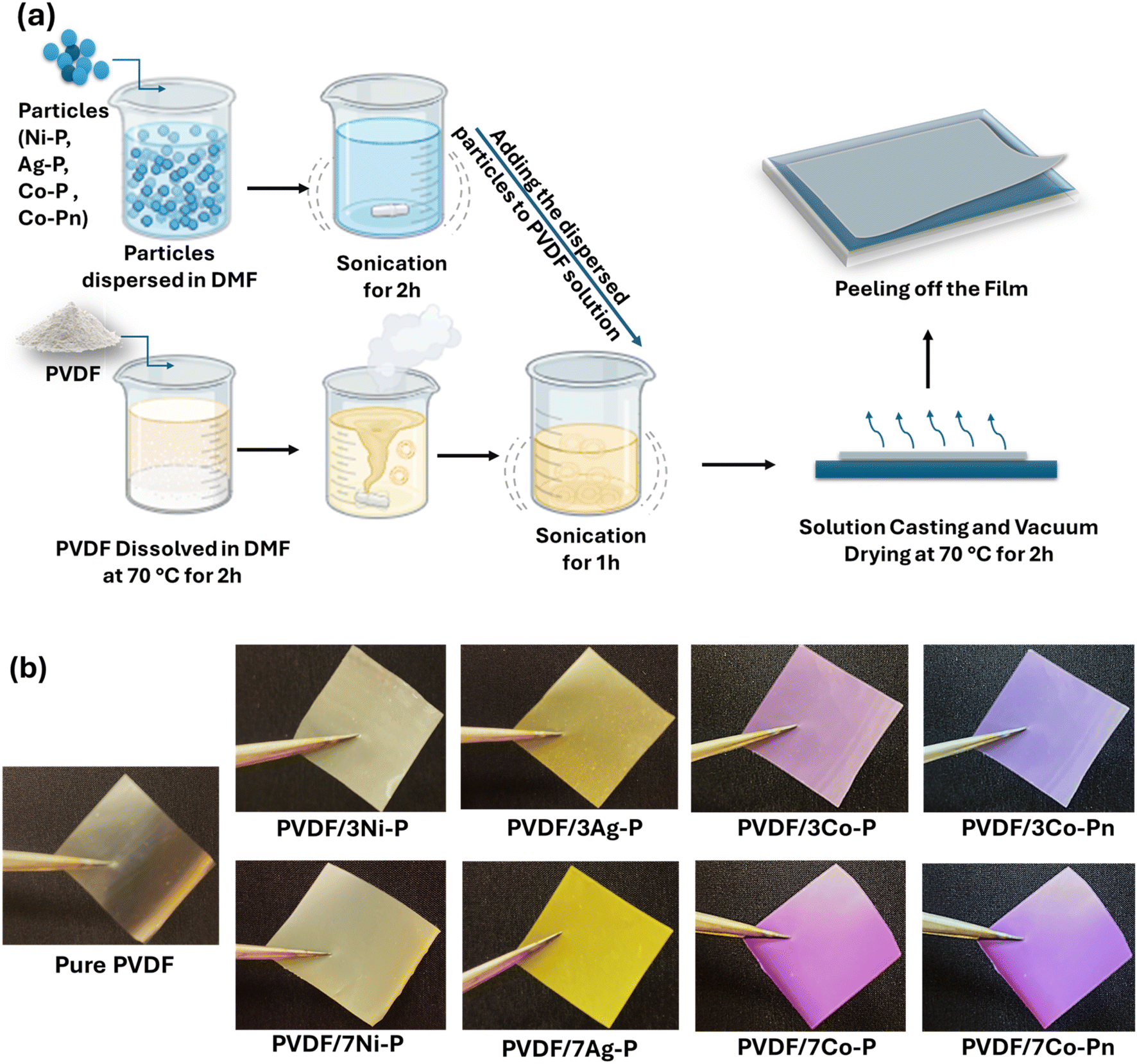 | ||
| Fig. 2 Schematic representation of (a) the composite film synthesis protocol, (b) image of the fabricated composite films. | ||
3. Characterization techniques
3.1. Structural characterization X-ray diffraction (XRD)
A Bruker D8 Discover was used to perform X-ray diffraction (XRD) characterization utilizing Cu Ka radiation (λ = 1.54184 nm) in the 2θ range of 10–70° for particle analysis and in the range of 15–25° for elaborated composite films. Whereas the current and voltage were maintained at 100 mA and 40 kV, respectively.3.2. Fourier transforms infrared spectroscopy
FTIR spectra of MP-Ps as well as neat PVDF, and PVDF composite films were conducted on FTIR, PerkinElmer Spectrum 2000 equipped with ATR accessory for the films, however KBR accessory for the powder. Each spectrum was obtained in 400–4000 cm−1 range in the case of nanocomposites meanwhile in the range of 600–4000 cm−1 for the powder of MP-Ps. The samples were analyzed with an accumulation of 16 scans and a resolution of 4 cm−1.3.3. Raman spectroscopy
The vibrations of the synthesized MP-Ps were investigated using Raman scattering spectroscopy using a HORIBA LABRAM-HR Evolution device under green laser illumination in the wavenumber range of 150–1000 cm−1.3.4. Scanning electron microscope
In order to characterize the shape of MP-Ps and assess their distribution inside the polymeric film matrix, a Zeiss EVO 10 scanning electron microscope (Carl Zeiss Microscopy, GmbH, Jena, Germany) was employed. To obtain a precise and clean fracture surface, the films were cryo-fractured using liquid nitrogen. Prior to scanning, the samples were made conductive by applying a gold coating using a sputtering process.3.5. Thermogravimetric analysis
The thermal stability and degradation behaviors of synthesized MP-Ps, neat PVDF as well as the composites films were conducted by thermographic analysis using TA instruments (Discovery TGA). Under a nitrogen atmosphere with a gas flow of 20 ml to prevent oxidation effects and heated between 25 and 700 °C at a heating rate of 10 °C min−1.3.6. Differential scanning calorimetry
The melting and crystallization behavior of elaborated films were investigated using Differential scanning calorimetry (DSC) (Discovery DSC, TA instruments). During the analysis process, the samples were gradually heated from 20 to 200 °C at a rate of 10 °C min−1. Then, they were held at 200 °C for three minutes to destroy any preceding thermal or mechanical effects. Next, the samples were cooled from 200 °C to −80 °C, also at a rate of 10 °C min−1, to further assist in observing their crystallization behavior. After a stabilization period of three minutes at −80 °C, the samples were heated back from −80 to 200 °C at the similar rate as before to examine their melting properties.The degree of crystallinity (Xc) was calculated according to the following equation:
3.7. Tensile test
The tensile characteristics of developed films were assessed using a universal testing machine (SHIMADZ, Kyoto, Japan) fitted with a 1 KN load cell in accordance with the ASTM D882-00 standard. With a measured gauge length of 50 mm and a moving clamp speed of 5 mm min−1, the film samples were cut into 10 × 50 mm2 rectangles. No fewer than five samples were used for each test, and the findings are average.3.8. Ferroelectric analysis
P–E hysteresis loops were obtained by Radiant Precision Workstation ferroelectric testing system at room temperature equipped with a high-voltage source of 10 kV. The Vision5 data management software was used to obtain results at a frequency of 5 hertz with the normal dipolar mode, which produced a triangular signal of high voltage and enabled us to measure the subsequent polarization of PVDF composite films.4. Results and discussions
4.1. Characterization of synthesized metal phosphate-based particles (MP-Ps)
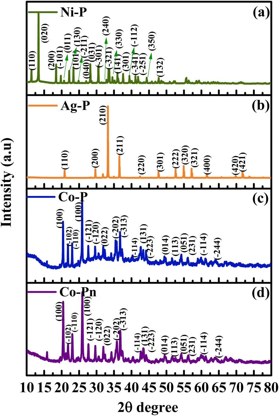 | ||
| Fig. 3 XRD diffractograms of synthesized (a) Ni–P, (b) Ag–P, (c) Co–P, (d) Co–Pn. | ||
Fourier Transform Infrared (FTIR) spectroscopy is an essential technique for characterizing the as-prepared particles, offering detailed insights into their molecular structure. By identifying unique vibrational modes, FTIR reveals the functional groups, bonding arrangements, and chemical composition of the particles. This information is crucial for confirming the successful synthesis and understanding the interactions within the material.39 The FTIR spectra of MP-Ps presented in Fig. 4 was used to further confirm their bonding arrangement. All spectra indicate the presence of characteristic bands at 882 cm−1, 741 cm−1, 597 cm−1, 580 cm−1, 557 cm−1, 556 cm−1 and 450 cm−1 referring to literature the vibrational bands occur within this range is (ν3) (F2) PO43− ascribed to the metal oxygen bond.40–42 Furthermore, the vibrational bands at 1005 cm−1,1049 cm−1, 1031 cm−1 and 1050 cm−1 are due to the triply degenerated (ν3) asymmetric stretching vibrations of P–O bonds.43 For the samples Ag–P, Ni–P there is the presence of a vibration bonds at 1665 cm−1 and 1622 cm−1 respectively, are ascribed to the H–O–H bending vibration from the structural water44–46 and also a broad peaks ranging 3500 cm−1 to 3000 cm−1 stretching vibration and O–H stretching in crystallization water.47 Furthermore, it is observed from the FTIR spectra of the Ag–P particles the presence of a bond at 3555 cm−1 related to hydroxyl group –OH adsorbed on the surface of the Ag–P particle via surface hydrolysis and protonation.48,49
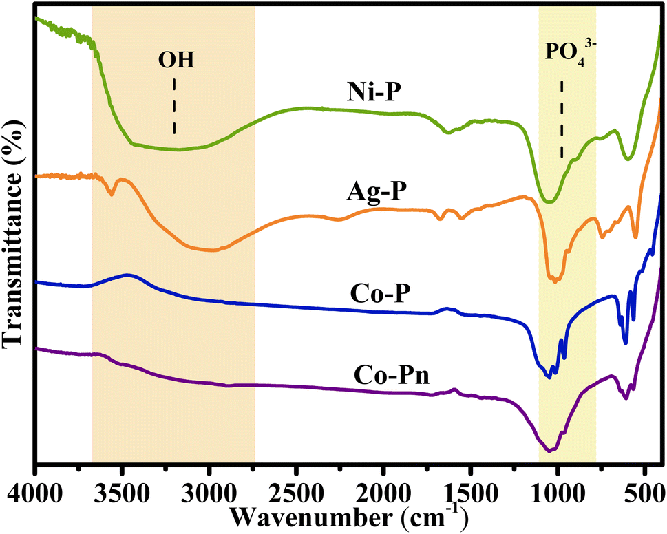 | ||
| Fig. 4 FTIR spectra of the synthesized MP-Ps. | ||
Raman spectroscopy is a highly reliable and widely used tool for characterizing materials, as it provides valuable information about the structural quality and can also reveal the presence of dopants or other modifications.50 Fig. 5 represents the Raman spectrum of MP-Ps. The internal modes in Raman spectroscopy typically involve the displacement of atoms within molecular units, such as the oxygen atoms in tetrahedral anions like (PO4)3−. These modes exhibit frequencies that are closely related to those of the free anion. For example, the free (PO4)3− ion displays a characteristic symmetric stretching mode (A1g) around 938 cm−1. In nickel phosphate, similar vibrational frequencies can be observed, reflecting the internal dynamics of the phosphate groups, the intense peak of 908 cm−1 is attributed to the terminal oxygen vibrational stretching of the PO4 group for the silver phosphate.51 The Raman peaks around 1000 cm−1 for the cobalt phosphate are from the triply degenerate n3 antisymmetric stretching vibrations (A1g + Eg) of the phosphate ligands.52
 | ||
| Fig. 5 Raman spectra of the synthesized (a) Ni–P, (b) Ag–P, (c) Co–P, (d) Co–Pn. | ||
 | ||
| Fig. 6 SEM images and EDX spectrum of the as-synthesized particles: (a) Ni–P, (b) Ag–P, (c) Co–P and (d) Co–Pn. | ||
For all the particles, the EDX spectrum confirmed the predictable chemical composition, while the elemental mapping images showed a uniform distribution of elements, indicating consistent synthesis (Fig. S1, ESI†). In summary, the diverse morphologies and scales of the synthesized materials, directly influenced by the different synthesis methods, are expected to play a crucial role in determining the overall structural, thermal, and electrical properties of the resulting composites. Furthermore, the particle size distribution and morphology are expected to impact on the dielectric and ferroelectric properties of the composites. This study is therefore vital in assessing how these MP-Ps can improve the ferroelectric behavior and β-phase content of PVDF, leading to high-performance materials.
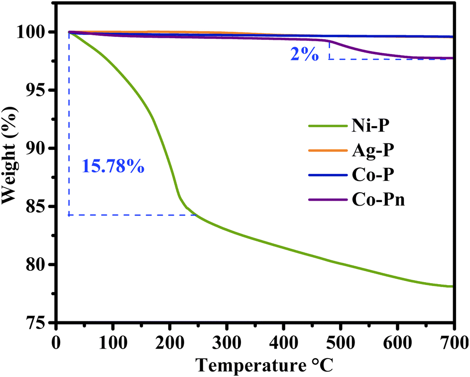 | ||
| Fig. 7 TGA curves of synthesized MP-Ps. | ||
 | ||
| Fig. 8 XRD patterns of composite films (a) PVDF/Ni–P, (b) PVDF/Ag–P, (c) PVDF/Co–P and (d) PVDF/Co–Pn. | ||
4.2. Characterization of composite films
 | ||
| Fig. 9 FTIR spectrum (a)–(d) along with β-phase percentage (e) of the elaborate composite films. | ||
The fraction of β-phase in different samples is displayed through quantitative measurement, which confirms this conversion even further. The following formula is used to determine β-phase percentage in PVDF:
 | (1) |
 | ||
| Fig. 10 SEM images of (a) neat PVDF, (b) cross-sectional view of composite films, and (c) surface morphology of composite films. | ||
For the composite PVDF/xAg–P, following a similar trend with the addition of 3 wt% of Ag–P as low percentage the surface shows to be smooth compared to pure PVDF with some minimal aggregation of particles in the surface, also from the cross section the surface is dense with relatively no agglomerations. Furthermore, the addition of 7 wt% of Ag–P with a high aspect ratio showing no obvious aggregation either on the surface nor in the cross-sectional part but with a globular structure and larger pores on the surface. Demonstrating a change in the crystalline structure. The shift from a globular structure to a smoother one can be explained by the fact that small blocks of lamella are pulled away from the original lamellae to form a fibrillar structure of crystallites, this microstructural alteration is linked to the α- to β-phase changeover.61 This aligns perfectly with the previously discussed findings from XRD and FTIR.
For the composite PVDF/xCo–P, a globular structure is observed at both low (3 wt%) and high (7 wt%) filler concentrations. At the lower concentration, the surface appears denser with minimal voids, while larger pores become evident at higher filler concentrations. This structural change is attributed to matrix modification. At higher filler levels, some particles are partially embedded in the surface, appearing both exposed and immersed, which increases surface roughness compared to pure PVDF. Cross-section reveals a dense surface with no visible particle agglomeration. The absence of gaps between the particles and the matrix suggests strong interactions between the polymer and the particles.62
In contrast, for the composite PVDF/xCo–Pn, smooth surfaces are observed at both filler concentrations, with the particles fully embedded within the film surface. Cross-sectional examination indicates that the particles are well incorporated into the polymer matrix without observable gaps. However, minor voids are noted, potentially caused by particle pull-out during fracture.62 This phenomenon is more prominent at higher filler concentrations and could be linked to the initiation of agglomeration, which may hinder interactions between the polymer and the fillers. These observations align with previous findings, where the β-phase content decreases at higher filler concentrations, indicating reduced interactions between the polymer matrix and the fillers.
This leads us to the conclusion that the structure and interactions within the host polymer matrix are significantly impacted by the morphology of the filler particles, which leads to modifications in the overall properties of the composite.63 Dispersion of the fillers is another important issue that can have a big impact on the performance of the composite. Particle agglomeration can produce stress concentration points, which is well recognized in composite materials and may weaken the mechanical properties of the composite.64 Achieving good dispersion, as seen in most of the composites, plays a critical role in improving their mechanical performance.
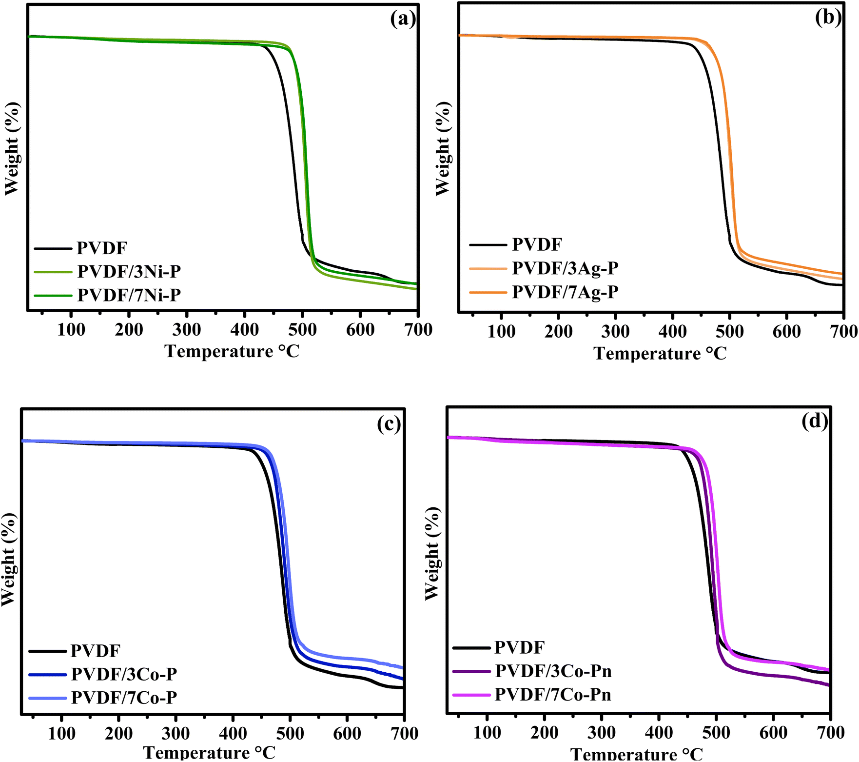 | ||
| Fig. 11 TGA curves of PVDF and composite films (a) PVDF/Ni–P, (b) PVDF/Ag–P, (c) PVDF/Co–P and (d) PVDF/Co–Pn. | ||
| Samples | Tonset (°C) | Tmax (°C) | Char content% |
|---|---|---|---|
| PVDF neat | 470.44 | 484.30 | 23.21 |
| PVDF/3Ni–P | 490.79 | 499.46 | 21.34 |
| PVDF/7Ni–P | 495.36 | 503.93 | 23.15 |
| PVDF/3Ag–P | 489.66 | 503.31 | 25.33 |
| PVDF/7Ag–P | 490.42 | 505.77 | 26.88 |
| PVDF/3Co–P | 473.99 | 490.69 | 25.92 |
| PVDF/7Co–P | 483.19 | 498.70 | 29.36 |
| PVDF/3Co–Pn | 476.06 | 499.46 | 24.45 |
| PVDF/7Co–Pn | 489.64 | 503.77 | 19.08 |
From the current data it is observed that the pure PVDF film is stable up to 340 °C, after which follows a one-step degradation. The process of breakdown seen in pure PVDF involves the carbon–hydrogen bond breaking, which produces hydrogen fluoride, and then more hydrogen fluoride loss throughout the polymer chains.66 The incorporation of MP-Ps into the PVDF matrix resulted in a notable increase in the onset degradation temperature of the composites, indicating a significant enhancement in the thermal stability of PVDF when combined with MP-Ps.67 Moreover, the thermal stability further improved with increasing filler content in the composites. The first derivative peak temperature of pure PVDF was observed at 484 °C. For composites containing Ni–P filler, the peak temperatures were 500 °C and 505 °C for 3 wt% and 7 wt%, respectively. Similarly, PVDF/xAg composites exhibited peak temperatures of 503.31 °C and 505.77 °C for 3 wt% and 7 wt%, respectively. Composites with Co–P particles showed peak temperatures of 490.69 °C and 498.70 °C for 3 wt% and 7 wt%, respectively, while composites with Co–Pn particles displayed peak temperatures of 499.46 °C and 503.77 °C for 3 wt% and 7 wt%, respectively.
The thermal behavior of the PVDF composites can be directly linked to the thermal characteristics of the incorporated MP-Ps depicted in Fig. 7. The improved thermal stability observed in the composites is influenced by the high thermal resilience of MP-Ps particles like Ag–P and Co–P, which exhibit no significant degradation in TGA analysis. These stable particles enhance the overall thermal performance of the PVDF matrix. Conversely, the degradation stages of Ni–P and Co–Pn, associated with water loss and organic residue decomposition, suggest that their influence on the composite's stability is partly due to these factors. Nonetheless, the uniform dispersion of MP-Ps within the PVDF matrix likely mitigates these effects, contributing to the observed increase in the degradation temperatures, especially at higher filler concentrations.68
Understanding the effect of these fillers on the enhanced thermal stability of the composite requires first examining the degradation mechanism of PVDF. This will help determine whether the improvements are linked to phase transitions and changes in the crystalline structure, as previously noted in other analyses. Hence, to create C–C double bonds, the PVDF begins with the generation of free radicals by first scissoring the –C–H bond and then the –C–F bond.69 The elimination of hydrogen fluoride is subsequently spread across the chains of polymers. Thus, mass loss happens in two stages: HF elimination and the polymer chain's disintegration. Meanwhile, there are other factors involved in this enhancement. MP-Ps can function as radical scavengers, effectively inhibiting chain transfer reactions and preventing the decomposition of polymer chains. As a result, the nucleation rate is reduced, requiring more time for volatiles to accumulate to a critical concentration.70 This leads to an improvement in the thermal stability of the composite compared to neat PVDF.
Notably, the char content shows an increase for composites containing Ag–P and Co–P, while a decrease is observed for composites containing Ni–P and Co–Pn. The improvement in char content for composites containing Ag–P and Co–P can be attributed to the inherent thermal stability and high thermal resilience of these particles. Both Ag–P and Co–P exhibit minimal or no significant degradation during TGA analysis, as they lack water content and organic residues that contribute to weight loss. This stability ensures that these particles form a robust, thermally resistant residue at higher temperatures, thereby increasing the char content in the composites. In contrast, composites containing Ni–P and Co–Pn show relatively lower char content due to the thermal behavior of these particles. Ni–P undergoes significant weight loss in two degradation stages, primarily due to the loss of physically adsorbed water and decomposition of chemically bound crystalline water. Similarly, Co–Pn exhibits degradation related to the loss of water and the breakdown of surface-bound organic residues. These processes reduce the amount of stable residue remaining at higher temperatures, resulting in a lower char content in the composites.
Likewise, the melting and crystallization behaviors of PVDF and PVDF composites are measured using a DSC analyzer. Additional insights into the influence of fillers on polymer crystallinity are obtained through these DSC determinations. The melting temperature (Tm), enthalpy of melting (ΔHm), crystallization temperature (Tc), and crystalline (Xc) were extracted from the DSC curves, as shown in Fig. 12 and Table 2. These parameters provide valuable insights into the thermal behavior and stability of the materials. The melting temperature of pure PVDF was found to be 162.94 °C. With the addition of the fillers, it was observed that melting endotherms are broader, and their peak temperatures shifted slightly to lower temperatures. Changes in the melting temperature can be attributed to alterations in the crystal structures of PVDF within the composites. This suggests that the formation of double bonds during the reaction may slightly modify the main chains of PVDF, thereby affecting the melting temperature. This phenomenon can confirm the presence of the β-phase, which is known to have a melting point lower than that of the α phase crystal of PVDF, as documented in the literature.67,71,72 The changes observed in each composite depend on its composition. Variations in melting points suggest differences in particle-PVDF interactions, which align with SEM images showing distinct morphological modifications in each material. Furthermore, in the same tendency the melting enthalpy and crystallinity shows a significant increment, which means that more energy is required to break the crystalline structure which indicates stronger intermolecular interactions confirming the FTIR finding. The presence of strong intermolecular interactions, such as hydrogen bonding or dipole–dipole interactions, within the composite film can contribute to higher melting enthalpy. In the case of PVDF composites, if the β-phase is prevalent, the strong polar interactions between the parallel dipoles in the TTT conformation would be a factor and that could be explained by the previous result from the XRD and FTIR.13 The inclusion of fillers or additives in the composite film can enhance the crystallization process or reinforce the polymer matrix, contributing to the increased melting enthalpy. These fillers could act as nucleating agents, promoting the formation of crystalline regions. High crystallinity often leads to improved mechanical properties, such as increased stiffness, tensile strength, and toughness. The composite films would be more robust, and durable compared to neat PVDF.
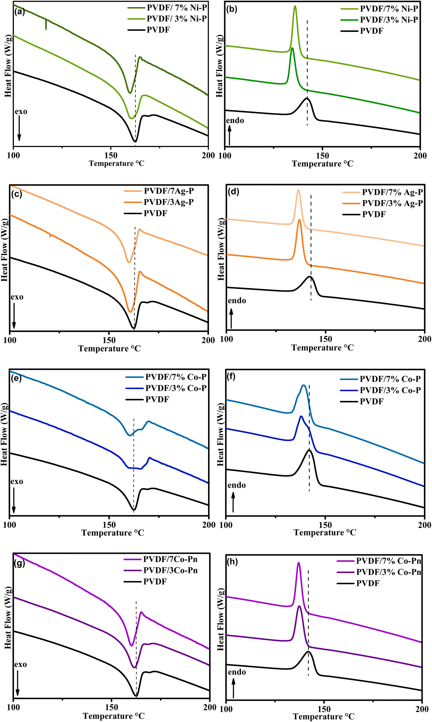 | ||
| Fig. 12 DSC curves of PVDF and composite films (a and b) PVDF/Ni–P, (c and d) PVDF/Ag–P, (e and f) PVDF/Co–P and (g and h) PVDF/Co–Pn. | ||
| Samples | Tm (°C) | ΔHm (J g−1) | Xc (%) |
|---|---|---|---|
| PVDF neat | 162.49 | 18.67 | 17% |
| PVDF/3Ni–P | 160.33 | 21.76 | 21% |
| PVDF/7Ni–P | 159.76 | 24.76 | 25% |
| PVDF/3Ag–P | 160.74 | 27.89 | 27% |
| PVDF/7Ag–P | 160.20 | 26.13 | 27% |
| PVDF/3Co–P | 159.91 | 19.60 | 20% |
| PVDF/7Co–P | 159.91 | 20.32 | 21% |
| PVDF/3Co–Pn | 161.44 | 22.47 | 22% |
| PVDF/7Co–Pn | 159.88 | 27.07 | 28% |
Therefore, comprehensive tensile test has been carried out to examine the effects of the shape and size of the synthesized particles (Ni–P, Ag–P, Co–P and Co–Pn) and their interactions, particularly their interfacial adhesion within the PVDF host matrix on the overall properties of the prepared composites. The tensile stress–strain graph provides key parameters: Young's modulus, tensile strength, and strain at break. Young's modulus reflects the material's ability to store mechanical energy during elastic deformation.74 Tensile strength which is known as the maximum stress that a material can resist when subjected to uniaxial tensile. Strain at break indicates ductility, with higher values signifying greater flexibility.22 The findings are shown in detail in Fig. 13.
 | ||
| Fig. 13 Tensile test of neat PVDF and the composites: (a) Young's modulus, (b) tensile strength, and (c) strain at break. | ||
The results indicate that all the produced composites exhibit a significant improvement in Young's modulus compared to neat PVDF. Composites containing Ni–P and Ag–P demonstrated similar enhancements at both loading percentages (3 wt% and 7 wt%), with their Young's modulus exceeding twice the value of neat PVDF. Meanwhile, composites with Co–P also showed improved Young's modulus, although the enhancement was moderate compared to PVDF/xNi–P and PVDF/xAg–P. In contrast, composites filled with Co–Pn displayed a distinct behavior: a significant improvement in Young's modulus was observed at 3 wt% loading, but the modulus decreased at higher particle loading (7 wt%). It is reported that the Young's modulus is generally insensitive to the particles size and generally increased with increasing particles loading since rigid inorganic MP-Ps generally have a much higher stiffness than polymer matrix.74 This increase with an increase in fillers fraction, as expected due to the higher intrinsic strength and stiffness of these particles compared with the PVDF matrix. Suggesting their excellent reinforcing effect as they make the composites stiffer by restricting the mobility of PVDF macromolecules under tensile stress. Such significant improvements in mechanical properties are largely attributed to the good dispersion of the fillers and their very high specific surface areas that help distribute load from the polymer matrix to the fillers.15,76 In contrast to the other composites, we find that composite PVDF/7Co–Pn has a noticeably lower Young's modulus. The reason behind this decrement could be directly supported by the prior assumption from SEM observation that there are tiny voids in this composition, most likely brought on by the initial phase of agglomeration. Factors like entangled molecular chains, voids, and other defects usually weaken and decrease stiffness, which has a negative impact on the mechanical properties.76
The effect of different particle loading on the tensile strength of the composite polymer also is discussed. As was discussed previously, tensile test results showed an increase in elastic modulus with increasing powder loading using different MP-Ps (Ni–P, Ag–P, Co–P and Co–Pn) with different size and morphology. In contrast, the tensile strength of the composite generally decreased with increasing particles loading beyond. This refers to a variety of parameters. It is demonstrated that the strength of composites is determined not only by particle size and particle/matrix interfacial adhesion but also by particle loading.77 From the available data, it is observed that there is an enhancement in the strength of particularly all the composite materials with Ni–P, Ag–P, Co–P and Co–Pn with both 3 wt% and 7 wt% of loading, this could be interpreted in first class by the excellent adhesion between this particles and the PVDF matrix, related to the interaction acquiring between this latter and the host matrix as it is evident from the previous founding supports by the XRD and FTIR. The tensile strength of polymer-based composites is significantly influenced by the quality of filler dispersion within the host matrix and the interfacial interactions between the fillers and the polymer. For flake-like Co–Pn particles, a 3 wt% loading demonstrates higher tensile strength due to better dispersion and enhanced stress transfer at the interface, resulting in superior reinforcement. In contrast, at 7 wt% loading, the tensile strength decreases, likely due to filler agglomeration, which creates stress concentrations and weakens the polymer–filler interface.74 The planar morphology of flakes allows for reinforcement in two dimensions, offering higher mechanical performance when the fillers are well-aligned and evenly distributed.78 Poor dispersion, however, can lead to low interfacial adherence, compromising the composite's tensile strength.79
By evaluating the elongation at the break parameter, the produced films containing Ni–P, Ag–P, Co–P, and Co–Pn particles were further examined for ductility and flexibility. The composites capacity to withstand significant deformation prior to failure is shown by their greatest elongation value.80 The findings indicate that composites containing 3 wt% of fillers exhibit the highest elongation at break. For composites with PVDF/xNi–P, similar elongation at break is observed for both filler loadings (x = 3 wt% and 7 wt%), which can be attributed to the homogeneous dispersion and strong adhesion between the nanoparticles and the PVDF matrix, as previously confirmed by SEM analysis. As discussed, XRD and FTIR result also confirm these strong interactions. Further supported by the enhancement of the β-phase at higher filler percentages. The improved interaction can be linked to the small size and large surface area of the nanoparticles, which increases interfacial adhesion and promotes better compatibility with the polymer matrix. For PVDF/xAg–P and PVDF/xCo–P composites, a similar trend is observed, with elongation at break being enhanced at 3 wt% filler loading but decreasing at 7 wt% loading. This decrease can be attributed to the initiation of particle aggregation at higher loadings, which directly impacts interfacial adhesion. Consequently, this weakens the matrix–filler interaction, leading to the observed reduction in elongation at break with increased filler content. For composite PVDF/xCo–Pn different behavior is remarqued with enhancement of the it could relate to the planar morphology of these flakes like particles providing large contact area, which resulted in the increase in strain at break providing more flexibility and ductility.81
To conclude, the study highlights the significant influence of particle type, size, morphology, and loading on the mechanical properties of PVDF composites. The incorporation of MP-Ps (Ni–P, Ag–P, Co–P, and Co–Pn) enhances Young's modulus and tensile strength due to improved filler dispersion, interfacial adhesion, and stress transfer within the matrix. However, excessive filler loading, particularly with flake-like Co–Pn particles, leads to agglomeration, void formation, and reduced mechanical performance. The ductility and flexibility of the composites are optimized at lower filler loadings (3 wt%), making these materials promising for applications in energy harvesting and piezoelectric devices where mechanical robustness and flexibility are critical.
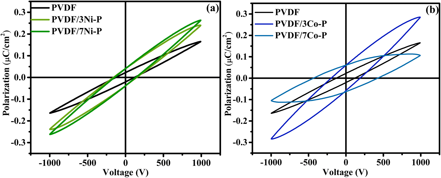 | ||
| Fig. 14 PE-hysteresis loops of PVDF and composite films: (a) PVDF/Ni–P, (b) PVDF/Co–P. | ||
| Composite | β-Phase content (%) | Surface morphology (SEM) | Mechanical performance | Filler dispersion | Remarks |
|---|---|---|---|---|---|
| Pure PVDF | ∼42 | Globular, porous surface | Low mechanical strength | No filler | Low β-phase, porous, weak mechanical profile |
| PVDF/3Ni–P | 89 | Smoother surface, uniform structure | Improved strength & flexibility | Homogeneous | Good β-phase, good matrix integration |
| PVDF/7Ni–P | 91 | Dense, smooth, non-porous morphology | High strength and elasticity | Excellent | Best overall performance; high crystallinity |
| PVDF/3Ag–P | 96 | Smooth, minor surface aggregates | Moderate mechanical strength | Fairly uniform | High β-phase, moderate interaction |
| PVDF/7Ag–P | 92 | Rougher, large pores | Weakened at higher filler | Acceptable | Surface roughness reduces performance |
| PVDF/3Co–P | 81 | Dense with minimal voids | Decent performance | Good | Stable morphology with minor modification |
| PVDF/7Co–P | 73 | Larger pores, exposed filler particles | Reduced strength | Partial agglomeration | Surface irregularities affect properties |
| PVDF/3Co–Pn | 91 | Smooth, embedded particles | Good at lower loading | Well distributed | Slight voids from pull-out noted |
| PVDF/7Co–Pn | 68 | Smooth, minor voids | Lower strength due to voids | Moderate | Onset of agglomeration; reduced β-phase |
For PVDF/Ni–P composites, the remnant polarization (Pr) doubles from 0.02 μC cm−2 in pure PVDF to 0.04 μC cm−2 at 3 wt% loading, while the maximum polarization (Pmax) significantly increases from 0.16 μC cm−2 to 0.26 μC cm−2. This enhancement can be attributed to the nucleation effect of Ni–P particles on β phase formation, which enables more effective dipole alignment under applied electric fields as previously discussed in the XRD and FTIR section.83 At 7 wt% Ni–P loading, Pr maintains its value (0.04 μC cm−2), but Pmax shows a slight decrease to 0.23 μC cm−2, suggesting that while dipole retention remains stable, the overall polarization capability becomes partially hindered at higher filler concentrations.83,84
The PVDF/Co–P system exhibits distinct behaviour compared to its Ni–P. Remnant polarization increases progressively from 0.02 μC cm−2 in pure PVDF to 0.05 μC cm−2 at 3 wt% and further to 0.06 μC cm−2 at 7 wt%, demonstrating superior dipole stabilization with increasing Co–P content. However, while the maximum polarization initially increases from 0.16 μC cm−2 in pure PVDF to 0.28 μC cm−2 at 3 wt%, it dramatically decreases to 0.10 μC cm−2 at 7 wt%, representing a reduction of approximately 64% compared to the 3 wt% loading and falling below even the pure PVDF value. This substantial drop indicates that while Co–P particles effectively enhance remnant polarization through stabilization of polarized domains, they significantly impede the total achievable polarization at higher concentrations. The higher Pr values observed for Co–P composites suggest stronger interfacial interactions that stabilize the polar β phase, consistent with the higher electronegativity of cobalt compared to nickel.85 However, the sharp decrease in Pmax for PVDF/7Co–P indicates that beyond a critical concentration level, these particles begin to act as defect sites that impede complete domain alignment under applied fields.86
The enhanced ferroelectric response in these composites originates from two primary mechanisms. First, increased β phase content with its inherently higher dipole moment per unit cell and also enhanced interfacial polarization at the filler-polymer boundaries. At moderate filler concentrations (3 wt%), these mechanisms operate synergistically, while at higher loadings (7 wt%), particularly for Co–P, competing effects of polarization enhancement and matrix disruption become evident.87 The SEM observations also support this interpretation, where signs of agglomeration and non-uniform dispersion were observed at higher filler loadings, particularly for the Co–P composite. These microstructural discontinuities likely contribute to the observed decrease in maximum polarization by creating local disturbances in the electric field distribution.87 These results indicate that optimal ferroelectric properties for potential applications in energy harvesting and sensing devices are achieved at moderate filler concentrations (approximately 3 wt% for both systems), where enhancement of β phase content and interfacial polarization operate without significantly disrupting the polymer matrix continuity.
When comparing our results with literature reports, the PVDF/Co–P and PVDF/Ni–P composites demonstrate remarkable ferroelectric performance with relatively low filler loadings. As shown in Table 4, our PVDF/3Co–P composite achieves a remnant polarization of 0.05 μC cm−2 with only 3 wt% loading and 81% β phase content, while PVDF/7Ni–P reaches a Pr of 0.04 μC cm−2 with 7 wt% loading and 91% β-phase content. These values are comparable to or exceed those reported for others research groups despite our significantly lower filler concentrations. These results highlight the exceptional efficiency of MP-Ps as fillers for enhancing PVDF's ferroelectric properties at minimal loading levels, demonstrating remarkable potential for next-generation piezoelectric energy harvesting systems where high performance to weight ratio and cost-effectiveness are crucial design parameters.
| Composite system | Preparation method | Filler content (wt%) | β-Phase (%) | Pr (μC cm−2) | Reference |
|---|---|---|---|---|---|
| PVDF/3Co–P (this work) | Solution casting | 3 | 81 | 0.05 | Present study |
| PVDF/7Ni–P (this work) | Solution casting | 7 | 91 | 0.04 | Present study |
| PVDF/CoFe2O4 | Spin coating | 15 | ∼80 | 0.0006 | 83 |
| (0.8)PVDF/(0.2)BaTiO3 | Solution mixing method | 20 | — | 0.045 | 88 |
| ϕBNT + (1 − ϕ)PVDF | Solution casting | 5 | ∼50 | 0.025 | 89 |
| 15PZNT | Drop casting technique | 15 | 88.9 | 0.035 | 90 |
5. Conclusion
In this work, we successfully developed novel PVDF/metal phosphate (MP-Ps) composite materials with significantly enhanced ferroelectric properties, representing a substantial advancement in the field of energy harvesting and flexible electronics. The structural, thermal, mechanical, and ferroelectric properties of the composites were systematically investigated, yielding quantitative and novel findings. Flexible composite films with β-phase content improvements ranging from 68% to 96% and superior ferroelectric responses were fabricated using the solution casting method, demonstrating their potential for high-performance applications.The SEM analysis revealed exceptional dispersion of MP-Ps within the PVDF matrix, a key factor contributing to the mechanical property enhancements. Strong interfacial interactions enabled by this uniform dispersion resulted in tensile strength improvements of up to 181.83% and Young's modulus increases reaching 184.76% (both in PVDF/3Co–Pn). In addition, the incorporation of MP-Ps led to notable improvements in thermal stability, with onset degradation temperature increases of 24.92 °C (PVDF/7Ni–P) and maximum degradation temperature enhancements of 21.47 °C (PVDF/7Ag–P), underscoring the multifunctional potential of these composites.
The impact of MP-Ps on ferroelectric performance was particularly remarkable. PVDF/7Co–P composites showed a 200% increase in remnant polarization (from 0.02 to 0.06 μC cm−2), and PVDF/3Co–P exhibited a 75% increase in maximum polarization (from 0.16 to 0.28 μC cm−2). These improvements were driven by the synergistic effects of enhanced β-phase content and homogeneous filler dispersion, emphasizing the pivotal role of particle morphology and matrix interaction in tuning the material's functional performance.
Based on the comprehensive analysis across all formulations (Table 2), PVDF/7Ni–P was identified as the most promising system, offering the best balance of structural integrity, thermal robustness, mechanical reinforcement, and ferroelectric response. Unlike the Co–P composites, which exhibited agglomeration at higher loadings despite strong ferroelectricity, PVDF/7Ni–P maintained consistent property enhancement with excellent dispersion and structural homogeneity, marking it as the most practically viable candidate.
In summary, the incorporation of MP-Ps into the PVDF matrix proves to be an effective strategy for the development of high-performance composite films with quantifiable, synergistic enhancements across structural, thermal, mechanical, and ferroelectric domains. The significant improvements observed in this study up to 96% β-phase content, 184.76% increase in mechanical strength, 24.92 °C rise in thermal stability, and 200% increase in remnant polarization, underline the transformative potential of metal phosphate nanoparticles in designing next-generation functional materials for flexible energy harvesting systems and advanced electronic applications.
Data availability
The data that support the findings of this study are available from the corresponding author, Fatima-Zahra SEMLALI, upon reasonable request.Conflicts of interest
There are no conflicts to declare.Acknowledgements
We would like to thank the Moroccan Ministry of Higher Education, Scientific Research and Innovation and the OCP Foundation who funded this work through the APRD research program.References
- Q. Zhu, K. Zhang, D. Li, N. Li, J. Xu and D. W. Bahnemann, et al., Polarization-enhanced photocatalytic activity in non-centrosymmetric materials based photocatalysis: A review, Chem. Eng. J., 2021, 426, 131681, DOI:10.1016/j.cej.2021.131681.
- A. Ahmed, A. Singh and S. Arya, High performance Mn doped ZnO loaded rGO electrode and its practical application as an electrode for self-charging supercapacitor device, J. Energy Storage, 2025, 105, 114783, DOI:10.1016/j.est.2024.114783.
- S. K. Karan, D. Mandal and B. B. Khatua, Self-powered flexible Fe-doped RGO/PVDF nanocomposite: An excellent material for a piezoelectric energy harvester, Nanoscale., 2015, 7(24), 10655–10666 RSC.
- S. Douhi, A. Eddiai, S. Das, B. T. P. Madhav, M. Meddad and O. Cherkaoui, et al., Design of a compact super wideband all-textile antenna for radio frequency energy harvesting and wearable devices, Opt. Quant. Electron., 2023, 55(13), 1–23, DOI:10.1007/s11082-023-05498-x.
- B. Maamer, A. Boughamoura, A. M. R. Fath El-Bab, L. A. Francis and F. Tounsi, A review on design improvements and techniques for mechanical energy harvesting using piezoelectric and electromagnetic schemes, Energy Convers. Manag., 2019, 199, 111973, DOI:10.1016/j.enconman.2019.111973.
- M. Liu, F. Qian, J. Mi and L. Zuo, Biomechanical energy harvesting for wearable and mobile devices: State-of-the-art and future directions, Appl. Energy, 2022, 321, 119379, DOI:10.1016/j.apenergy.2022.119379.
- S. Douhi, S. Labihi, A. Eddiai, S. Lakrit, M. El Achaby and A. J. A. Al-Gburi, Design, characterization, and electromagnetic performance of a flexible wideband RF antenna using composite materials, J. Sci. Adv. Mater. Devices, 2025, 10(1), 100847, DOI:10.1016/j.jsamd.2024.100847.
- A. Ahmed, S. Arora, S. Rasgotra, A. Dubey, A. Singh and R. Singh, et al., Synthesis and characterization of low-density polyethylene (LDPE) bubble wrap-derived reduced graphene oxide for triboelectric nanogenerator electrodes, Mater. Sci. Eng. B, 2025, 311, 117828, DOI:10.1016/j.mseb.2024.117828.
- S. Labihi, A. Eddiai, M. El Achaby, M. Rguiti and M. Mazroui, Enhancing β-phase and dielectric properties of BCZT lead-free reinforced in PVDF-HFP composite thick films for eco-friendly energy harvesting, Ceram. Int., 2024, 50(21PA), 40814–40822, DOI:10.1016/j.ceramint.2024.07.363.
- S. Arya, A. Sharma, A. Singh, A. Ahmed, A. Dubey and B. Padha, et al., Review—Energy and Power Requirements for Wearable Sensors, ECS Sens. Plus, 2024, 3(2) DOI:10.1149/2754-2726/ad54d2.
- E. S. Kadir, R. N. Gayen, R. Paul and S. Biswas, Interfacial effects on ferroelectric and dielectric properties of GO reinforced free-standing and flexible PVDF/ZnO composite membranes: Bias dependent impedance spectroscopy, J. Alloys Compd., 2020, 843, 155974, DOI:10.1016/j.jallcom.2020.155974.
- S. Barrau, A. Ferri, A. Da Costa, J. Defebvin, S. Leroy and R. Desfeux, et al., Nanoscale Investigations of α- And γ-Crystal Phases in PVDF-Based Nanocomposites, ACS Appl. Mater. Interfaces, 2018, 10(15), 13092–13099 CrossRef CAS.
- A. Gradys and P. Sajkiewicz, Determination of the melting enthalpy of β phase of poly(vinylidene fluoride), e-Polymers, 2013,(019), 1–14 Search PubMed.
- A. Bhiogade, K. Nagamalleswari, P. Mandal and R. V. K. Mangalam, Improved pyroelectric effect in PVDF/BaTiO3 composite flexible films mediated by enhanced β – PVDF phase formation, J. Polym. Res., 2023, 30(8), 1–8, DOI:10.1007/s10965-023-03669-8.
- A. A. Tarhini and A. R. Tehrani-Bagha, Graphene-based Polymer Composite Films with Enhanced Mechanical Properties and Ultra-high In-plane Thermal Conductivity, Compos. Sci. Technol., 2019, 184, 107797, DOI:10.1016/j.compscitech.2019.107797.
- S. Labihi, N. Chakhchaoui, A. Eddiai, M. El Achaby, M. Meddad and O. Cherkaoui, et al., Enhancement of piezoelectric β-polymorph formation and properties of graphene oxide and PZT-incorporated in PVDF-HFP matrix for energy harvesting applications, Polym. Compos., 2023, 44(4), 2296–2304 CrossRef CAS.
- S. Luo, S. Yu, R. Sun and C. p. Wong, Nano Ag-Deposited BaTiO3 Hybrid Particles as Fillers for Polymeric Dielectric Composites: Toward High Dielectric Constant and Suppressed Loss, ACS Appl. Mater. Interfaces, 2014 DOI:10.1021/am404556c.
- J. Diani and K. Gall, Finite Strain 3D Thermoviscoelastic Constitutive Model, Society, 2006, 1–10 Search PubMed.
- S. Dogra, A. Ahmed, A. Dubey, R. Singh, A. Singh and A. K. Sundramoorthy, et al., Synthesis, characterization, and application of PVDF-PZT composite thin film separator for self-charging supercapacitors, Surf. Interfaces, 2024, 51, 104593, DOI:10.1016/j.surfin.2024.104593.
- S. Baayyad, Y. Esshouba, S. Barhoumi, E. K. Hlil, S. Ez-Zahraoui and F. Z. Semlali, et al., High-density polyethylene composites filled with micro- and nano-particles of nickel ferrite: magnetic, mechanical, and thermal properties, RSC Adv., 2024, 14(26), 18750–18763 RSC.
- S. Baayyad, F. Z. Semlali, E. K. Hlil, T. Mahfoud, H. El Moussaoui and M. El Achaby, Developing Ni0.5Zn0.5Fe2O4 ferrite with controlled particle size and morphology through optimized processing conditions of low energy solid state reaction, RSC Adv., 2024, 14(49), 36264–36272 RSC.
- C. Bahloul, S. Ez-zahraoui, A. Eddiai and O. Cherkaoui, RSC Advances Ferrite-doped rare-earth nanoparticles for nanocomposites, RSC Adv., 2024, 14, 38872–38887 RSC.
- J. X. Chen, J. W. Li, C. C. Cheng and C. W. Chiu, Piezoelectric Property Enhancement of PZT/Poly(vinylidenefluoride-co-trifluoroethylene) Hybrid Films for Flexible Piezoelectric Energy Harvesters, ACS Omega, 2022, 7(1), 793–803 CrossRef CAS.
- G. Magdy, A. H. Hassanin, I. Kandas and N. Shehata, PVDF nanostructures characterizations and techniques for enhanced piezoelectric response: A review, Mater. Chem. Phys., 2024, 325, 129760, DOI:10.1016/j.matchemphys.2024.129760.
- H. Zhao and Z. Y. Yuan, Insights into Transition Metal Phosphate Materials for Efficient Electrocatalysis, ChemCatChem., 2020, 12(15), 3797–3810 CrossRef CAS.
- Q. Cheng, X. Zhao, G. Yang, L. Mao, F. Liao and L. Chen, et al., Recent advances of metal phosphates-based electrodes for high-performance metal ion batteries, Energy Storage Mater., 2021, 41, 842–882, DOI:10.1016/j.ensm.2021.07.017.
- P. Govindrao, N. W. Ghule, A. Haque and M. G. Kalaskar, Journal of Drug Delivery Science and Technology Metal nanoparticles synthesis : An overview on methods of preparation , advantages and disadvantages , and applications, J. Drug Deliv. Sci. Technol., 2019, 53, 101174, DOI:10.1016/j.jddst.2019.101174.
- P. Biswas, N. A. Hoque, P. Thakur, M. M. Saikh, S. Roy and F. Khatun, et al., Portable Self-Powered Piezoelectric Nanogenerator and Self-Charging Photo-Power Pack Using in Situ Formed Multifunctional Calcium Phosphate Nanorod-Doped PVDF Films, Langmuir, 2019, 35(52), 17016–17026 CrossRef CAS.
- E. Abdulkarem, Y. Ibrahim, M. Kumar, H. A. Arafat, V. Naddeo and F. Banat, et al., Polyvinylidene fluoride (PVDF)-α-zirconium phosphate (α-ZrP) nanoparticles based mixed matrix membranes for removal of heavy metal ions, Chemosphere, 2021, 267, 128896, DOI:10.1016/j.chemosphere.2020.128896.
- T. Pareek, S. Dwivedi, S. A. Ahmad, M. Badole and S. Kumar, Effect of NASICON-type LiSnZr(PO4)3 ceramic filler on the ionic conductivity and electrochemical behavior of PVDF based composite electrolyte, J. Alloys Compd., 2020, 824, 153991, DOI:10.1016/j.jallcom.2020.153991.
- H. Rekik, Z. Ghallabi, I. Royaud, M. Arous, G. Seytre and G. Boiteux, et al., Dielectric relaxation behaviour in semi-crystalline polyvinylidene fluoride (PVDF)/TiO2 nanocomposites, Composites, Part B, 2013, 45(1), 1199–1206, DOI:10.1016/j.compositesb.2012.08.002.
- C. F. Holder and R. E. Schaak, Tutorial on Powder X-ray Diffraction for Characterizing Nanoscale Materials, ACS Nano, 2019, 13(7), 7359–7365 CrossRef CAS.
- S. Kullyakool, C. Danvirutai, K. Siriwong and P. Noisong, Determination of kinetic triplet of the synthesized Ni3(PO 4)2·8H2O by non-isothermal and isothermal kinetic methods, J. Therm. Anal. Calorim., 2014, 115(2), 1497–1507 CrossRef CAS.
- S. S. Patil, J. C. Shin and P. S. Patil, Binder free hydrothermally synthesized nickel phosphate hydrate microplates on nickel foam for supercapacitors, Ceram. Int., 2022, 48(19), 29484–29492, DOI:10.1016/j.ceramint.2022.07.050.
- P. Amornpitoksuk, K. Intarasuwan, S. Suwanboon and J. Baltrusaitis, Effect of phosphate salts (Na3PO4, Na2HPO4, and NaH2PO4) on Ag3PO4 morphology for photocatalytic dye degradation under visible light and toxicity of the degraded dye products, Ind. Eng. Chem. Res., 2013, 52(49), 17369–17375 CrossRef CAS.
- Q. Liang, W. Ma, Y. Shi, Z. Li and X. Yang, Hierarchical Ag3PO4 porous microcubes with enhanced photocatalytic properties synthesized with the assistance of trisodium citrate, CrystEngComm., 2012, 14(8), 2966–2973 RSC.
- H. Liu, X. Peng, X. Liu, G. Qi and J. Luo, Porous Mn-Doped FeP/Co3 (PO4)2 Nanosheets as Efficient Electrocatalysts for Overall Water Splitting in a Wide pH Range, ChemSusChem, 2019, 12(7), 1334–1341 CrossRef CAS.
- J. Theerthagiri, K. Thiagarajan, B. Senthilkumar, Z. Khan, R. A. Senthil and P. Arunachalam, et al., Synthesis of Hierarchical Cobalt Phosphate Nanoflakes and Their Enhanced Electrochemical Performances for Supercapacitor Applications, ChemistrySelect, 2017, 2(1), 201–210 CrossRef CAS.
- C. Baudot, C. M. Tan and J. C. Kong, FTIR spectroscopy as a tool for nano-material characterization, Infrared Phys. Technol., 2010, 53(6), 434–438, DOI:10.1016/j.infrared.2010.09.002.
- P. Bhanja, Y. Kim, B. Paul, J. Lin, S. M. Alshehri and T. Ahamad, et al., Facile Synthesis of Nanoporous Transition Metal-Based Phosphates for Oxygen Evolution Reaction, ChemCatChem., 2020, 12(7), 2091–2096 CrossRef CAS.
- F. S. Omar, A. Numan, N. Duraisamy, S. Bashir, K. Ramesh and S. Ramesh, Ultrahigh capacitance of amorphous nickel phosphate for asymmetric supercapacitor applications, RSC Adv., 2016, 6(80), 76298–76306, 10.1039/C6RA15111F.
- I. Ahmed, R. Biswas, R. Sharma, V. Burman and K. K. Haldar, Access to carbon nanofiber composite hydrated cobalt phosphate nanostructure as an efficient catalyst for the hydrogen evolution reaction, Front. Chem., 2023, 11, 1–10 Search PubMed.
- V. P. Padmanabhan, P. Sivashanmugam, R. Kulandaivelu, S. Sagadevan, B. Sridevi and R. Govindasamy, et al., Biosynthesised Silver Nanoparticles Loading onto Biphasic Calcium Phosphate for Antibacterial and Bone Tissue Engineering Applications, Antibiotics, 2022, 11(12) DOI:10.3390/antibiotics11121780.
- A. Attia, Q. Wang, X. Huang and Y. Yang, Titanium phosphates as positive electrode in lithium-ion batteries: Composition, phase purity and electrochemical performance, J. Solid State Electrochem., 2012, 16(4), 1461–1471 CrossRef CAS.
- K. Kadiya, S. B. Vuggili, U. K. Gaur and M. Sharma, Comparative photocatalytic dye and drug degradation study using efficient visible light–induced silver phosphate nanoparticles, Environ. Sci. Pollut. Res., 2021, 28(34), 46390–46403 CrossRef CAS PubMed.
- J. Li, L. Zhang, P. Yang and X. Cheng, Morphological evolution of Co phosphate and its electrochemical and photocatalytic performance, CrystEngComm, 2018, 20(43), 6982–6988 RSC.
- L. Kumar and D. Ahuja, Preparation and characterization of aliphatic polyurethane and modified hydroxyapatite composites for bone tissue engineering, Polym. Bull., 2020, 77(11), 6049–6062, DOI:10.1007/s00289-019-03067-5.
- L. C. Chow, M. Markovic, S. A. Frukhtbeyn and S. Takagi, Hydrolysis of tetracalcium phosphate under a near-constant-composition condition - Effects of pH and particle size, Biomaterials, 2005, 26(4), 393–401 CrossRef CAS.
- Y. Li, Y. Wang, Y. Huang, J. Cao, W. Ho and S. Lee, et al., Controllable synthesis of phosphate-modified BiPO4 nanorods with high photocatalytic activity: Surface hydroxyl groups concentrations effects, RSC Adv., 2015, 5(121), 99712–99721 RSC.
- A. Samal, D. P. Das and G. Madras, Repercussion of Solid state vs. Liquid state synthesized p–n heterojunction RGO-copper phosphate on proton reduction potential in water, Sci. Rep., 2018, 1–19, DOI:10.1038/s41598-018-21239-7.
- H. H. Agbe, 2O2 rejuvenation-mediated synthesis of stable mixed-morphology Ag3PO4, Heliyon, 2018, e00599, DOI:10.1016/j.heliyon.2018.e00599.
- J. Qi, Y. p. Lin, D. Chen, T. Zhou, W. Zhang and R. Cao, Autologous Cobalt Phosphates with Modulated Coordination Sites for Electrocatalytic Water Oxidation Oxygen Evolution Reaction Autologous Cobalt Phosphates with Modulated Coordination Sites for Electrocatalytic Water Oxidation, Angew. Chem., Int. Ed., 2020 DOI:10.1002/anie.202001737.
- A. Brostrøm, K. I. Kling, K. S. Hougaard and K. Mølhave, Complex Aerosol Characterization by Scanning Electron Microscopy Coupled with Energy Dispersive X-ray Spectroscopy, Sci. Rep., 2020, 10(1), 1–15 CrossRef.
- C. H. Lin, S. K. Parthasarathi, S. Bolloju, M. Abdollahifar, Y. T. Weng and N. L. Wu, Synthesis of Micron-Sized LiNi0.8Co0.1Mn0.1O2 and Its Application in Bimodal Distributed High Energy Density Li-Ion Battery Cathodes, Energies, 2022, 15(21), 1–15 CrossRef.
- J. M. Rami, C. D. Patel, C. M. Patel and M. V. Patel, Thermogravimetric analysis (TGA) of some synthesized metal oxide nanoparticles, Mater. Today: Proc., 2020, 43, 655–659, DOI:10.1016/j.matpr.2020.12.554.
- X. Li, Y. Xiong, M. Duan, H. Wan, J. Li and C. Zhang, et al., Investigation on the adsorption-interaction mechanism of pb(ii) at surface of silk fibroin protein-derived hybrid nanoflower adsorbent, Materials, 2020, 13(5) DOI:10.3390/ma13051241.
- M. A. Ashraf, Z. Liu and W. X. Peng, Trisaminomethane–cobalt complex supported on Fe3O4 magnetic nanoparticles as an efficient recoverable nanocatalyst for oxidation of sulfides and C–S coupling reactions, Appl. Organomet. Chem., 2020, 34(1), 1–15 CrossRef.
- X. Cai, T. Lei, D. Sun and L. Lin, A critical analysis of the α, β and γ phases in poly(vinylidene fluoride) using FTIR, RSC Adv., 2017, 7(25), 15382–15389 RSC.
- C. Dayanand, G. Bhikshamaiah, V. Java Tyagaraju, M. Salagram and A. S. R. Krishna Murthy, Structural investigations of phosphate glasses: A detailed infrared study of the x(PbO)-(1 – X) P2O5 vitreous system, J. Mater. Sci., 1996, 31(8), 1945–1967 CrossRef CAS.
- A. A. Ribeiro, R. F. C. Marques, A. C. Guastaldi and J. S. De Carvalho Campos, Hydroxyapatite deposition study through polymeric process on commercially pure Ti surfaces modified by laser beam irradiation, J. Mater. Sci., 2009, 44(15), 4056–4061 CrossRef CAS.
- V. Sencadas, S. Lanceros-Méndez, I. Sabater, R. Serra, A. Andrio Balado and J. L. Gómez Ribelles, Relaxation dynamics of poly(vinylidene fluoride) studied by dynamical mechanical measurements and dielectric spectroscopy, Eur. Phys. J. E, 2012, 35(5) DOI:10.1140/epje/i2012-12041-x.
- S. Ez-Zahraoui, F. Z. Semlali, M. Raji, F. Z. Nazih, R. Bouhfid and A. E. K. Qaiss, et al., Synergistic reinforcing effect of fly ash and powdered wood chips on the properties of polypropylene hybrid composites, J. Mater. Sci., 2024, 59(4), 1417–1432, DOI:10.1007/s10853-023-09299-1.
- W. Ji, H. Deng, C. Guo, C. Sun, X. Guo and F. Chen, et al., The effect of filler morphology on the dielectric performance of polyvinylidene fluoride (PVDF) based composites, Compos. Part A Appl. Sci. Manuf., 2019, 118, 336–343 CrossRef CAS.
- M. Üniversitesi, S. Ersoy and M. Taşdemir, Zinc oxide (ZnO), magnesium hydroxide [Mg(OH)2] and calcium carbonate (CaCO3) filled HDPE polymer composites: Mechanical, thermal and morphological properties, Marmara J. Pure Appl. Sci., 2013, 24(4), 93–104 Search PubMed , available from: https://dergipark.org.tr/en/pub/marufbd/issue/17878/187433.
- N. Saadatkhah, A. Carillo Garcia, S. Ackermann, P. Leclerc, M. Latifi and S. Samih, et al., Experimental methods in chemical engineering: Thermogravimetric analysis—TGA, Can. J. Chem. Eng., 2020, 98(1), 34–43 CrossRef CAS.
- S. Shetty, A. Mahendran and S. Anandhan, Development of a new flexible nanogenerator from electrospun nanofabric based on PVDF/talc nanosheet composites, Soft Matter, 2020, 16(24), 5679–5688 RSC.
- T. Prabhakaran and J. Hemalatha, Flexible films of β-phase poly(vinylidene fluoride)/ZnFe2O4 polymer nanocomposite for magnetoelectric device applications, Sci. Adv. Mater., 2014, 6(7), 1313–1321 CrossRef CAS.
- A. M. AlAhzm, M. O. Alejli, D. Ponnamma, Y. Elgawady and M. A. A. Al-Maadeed, Piezoelectric properties of zinc oxide/iron oxide filled polyvinylidene fluoride nanocomposite fibers, J. Mater. Sci.:Mater. Electron., 2021, 32(11), 14610–14622, DOI:10.1007/s10854-021-06020-3.
- A. Issa, M. Al-Maadeed, A. Luyt, D. Ponnamma and M. Hassan, Physico-Mechanical, Dielectric, and Piezoelectric Properties of PVDF Electrospun Mats Containing Silver Nanoparticles, C, 2017, 3(4), 30 Search PubMed.
- J. Yu, X. Huang, C. Wu and P. Jiang, Permittivity, thermal conductivity and thermal stability of poly(vinylidene fluoride)/graphene nanocomposites, IEEE Trans. Dielectr. Electr. Insul., 2011, 18(2), 478–484 CAS.
- I. H. Kim, D. H. Baik and Y. G. Jeong, Structures, electrical, and dielectric properties of PVDF-based nanocomposite films reinforced with neat multi-walled carbon nanotube, Macromol. Res., 2012, 20(9), 920–927 CrossRef CAS.
- F. Liu, M. R. M. Abed and K. Li, Preparation and characterization of poly(vinylidene fluoride) (PVDF) based ultrafiltration membranes using nano γ-Al2O3, J. Membr. Sci., 2011, 366(1–2), 97–103 CrossRef CAS.
- Q. Wu, L. Li, Y. D. Zhang and W. J. Shui, Absorption and mechanical properties of SiCp/PVDF composites, Composites, Part B, 2017, 131, 1–7, DOI:10.1016/j.compositesb.2017.07.074.
- S. y. Fu, X. q. Feng, B. Lauke and Y. w. Mai, Effects of particle size , particle/matrix interface adhesion and particle loading on mechanical properties of particulate – polymer composites, Composites, Part B, 2008, 39, 933–961, DOI:10.1016/j.compositesb.2008.01.002.
- P. Cheang and K. A. Khor, Effect of particulate morphology on the tensile behaviour of polymer Á hydroxyapatite composites, Mater. Sci. Eng. A, 2003, 345, 47–54, DOI:10.1016/S0921-5093(02)00284-8.
- Y. Pang, J. Yang, T. E. Curtis, S. Luo, D. Huang and Z. Feng, et al., Exfoliated Graphene Leads to Exceptional Mechanical Properties of Polymer Composite Films, ACS Nano, 2019, 13(2), 1097–1106 CAS.
- J. Cho, M. S. Joshi and C. T. Sun, Science And Effect of inclusion size on mechanical properties of polymeric composites with micro and nano particles, Compos. Sci. Technol., 2006, 66, 1941–1952, DOI:10.1016/j.compscitech.2005.12.028.
- J. Rexer and E. Anderson, Composites with Planar Reinforcements (Flakes, Ribbonsk)-A Review, Polym. Eng. Sci., 1979, 19(1), 1–11, DOI:10.1002/pen.760190102.
- P. W. Balasuriya, L. Ye and Y. Mai, Mechanical Properties of Wood Ake ± Polyethylene Composites. Part I: Effects of Processing Methods and Matrix Melt Ow Behaviour, Composites, Part A, 2006, 32, 2001, DOI:10.1016/S1359-835X(00)00160-3.
- A. Janićijević, S. Filipović, A. Sknepnek, A. Salević-Jelić, R. Jančić-Heinemann and M. Petrović, et al., Structural, Mechanical, and Barrier Properties of the Polyvinylidene Fluoride-Bacterial Nanocellulose-Based Hybrid Composite, Polymers, 2024, 16(8) DOI:10.3390/polym16081033.
- H. He, G. Fan, F. Saba, Z. Tan, Z. Su and D. Xiong, et al., Enhanced distribution and mechanical properties of high content nanoparticles reinforced metal matrix composite prepared by flake dispersion, Composites, Part B, 2023, 252, 110514, DOI:10.1016/j.compositesb.2023.110514.
- J. F. Scott, Applications of modern ferroelectrics, Science, 2007, 315(5814), 954–959 CrossRef CAS.
- A. Bhiogade, K. Nagamalleswari, P. Mandal and V. K. M. Ramakrishnan, Flexible multiferroic PVDF/CoFe2O4 composite films for pyroelectric energy conversion, J. Mater. Sci., 2023, 58(47), 17805–17815, DOI:10.1007/s10853-023-09149-0.
- S. Dash, R. N. P. Choudhary, A. Kumar and M. N. Goswami, Enhanced dielectric properties and theoretical modeling of PVDF–ceramic composites, J. Mater. Sci. Mater. Electron., 2019, 30(21), 19309–19318, DOI:10.1007/s10854-019-02291-z.
- T. M. Vandana and R. Gupta, Thermal and mechanical energy harvester based on flexible PVDF/PLZT polymer-ceramic composites, J. Polym. Res., 2023, 30(8), 1–11, DOI:10.1007/s10965-023-03694-7.
- Q. Yang, Z. Shi, D. Ma, Y. He and J. Wang, Flexible PbTiO3-nanowires/P(VDF-TrFE) composite films and their dielectric, ferroelectric and pyroelectric properties, Ceram. Int., 2018, 44(12), 14850–14856, DOI:10.1016/j.ceramint.2018.05.118.
- S. Dash, H. Sankar, M. Ravikant and A. Kumar, Ferroelectric ceramic dispersion to enhance the β phase of polymer for improving dielectric and ferroelectric properties of the composites, Polym. Bull., 2021, 78(9), 5317–5336, DOI:10.1007/s00289-020-03372-4.
- M. Sharma, A. Gaur and J. K. Quamara, Effect of 80 MeV O6+ ion irradiation on structural, morphological, dielectric, and ferroelectric properties of (1–x)PVDF/(x)BaTiO3 nanocomposites, Ionics, 2020, 26(1), 471–481 CrossRef CAS.
- L. K. Pradhan, R. Pandey, S. Kumar and M. Kar, Lead free Bi0.5Na0.5TiO3 (BNT) and polyvinylidene fluoride (PVDF) based nanocomposite for energy storage applications, AIP Conf. Proc., 2018, 1953, 1–5 Search PubMed.
- S. Pratihar, A. Patra, A. Sasmal, S. K. Medda and S. Sen, Enhanced dielectric, ferroelectric, energy storage and mechanical energy harvesting performance of ZnO-PVDF composites induced by MWCNTs as an additive third phase, Soft Matter, 2021, 17(37), 8483–8495 RSC.
Footnote |
| † Electronic supplementary information (ESI) available. See DOI: https://doi.org/10.1039/d5ra01605c |
| This journal is © The Royal Society of Chemistry 2025 |