
 Open Access Article
 This Open Access Article is licensed under a
 Creative Commons Attribution 3.0 Unported Licence
Photocatalytic reduction of aqueous chromium(VI) by RuO2/g-C3N4 composite under visible light irradiation†
Yongjun Liu *,
Xiaohe Du and
Zhiming Huang
*,
Xiaohe Du and
Zhiming Huang
College of Environmental Science & Engineering, Dalian Maritime University, Dalian, 116026, P. R. China. E-mail: lyjglow@dlmu.edu.cn; Fax: +86-411-84727670; Tel: +86-411-84725275
First published on 20th May 2025
Abstract
Graphitic carbon nitride (g-C3N4) has been extensively investigated as a novel nonmetallic visible-light response photocatalyst. However, its uses in photocatalytic reductions were limited because of the sluggish oxygen evolution reaction (OER) and the resulting self-decomposition. In this paper, a ruthenium dioxide loaded g-C3N4 composite (RuO2/g-C3N4) was prepared by forced oxidative hydrolysis of ruthenium(III) chloride on the surface of g-C3N4 that was obtained by direct condensation polymerization of melamine. Photocatalytic reduction of aqueous Cr(VI) by it under illumination from a 400–410 nm light-emitting diode was examined. It was shown that the Cr(VI) reduction rate was much higher in RuO2/g-C3N4 than in pure g-C3N4. Without any sacrificial electron donor and at initial solution pH 2.3, Cr(VI) removal (200 mL and 0.5 mM) was 34% and 76.4% with 0.1 g pure g-C3N4 and 0.1 RuO2 (1.0 wt%)/g-C3N4, respectively. The optimum initial solution pH was 2.4. Methanol accelerates while acetone suppresses the Cr(VI) reduction significantly. Ferric ions catalyze the reduction, especially in the later stage. UV-Vis diffusion reflectance spectroscopy and theoretical analysis showed that RuO2 not only boosts the charge separation but also protects the g-C3N4 from decomposition by its extraordinary catalytic action for OER. The used RuO2/g-C3N4 was separated from the solution by microfiltration, with little leaching and residue remaining in the filtrate. The reclaimed RuO2/g-C3N4 was recycled for 5 cycles and no obvious decrease in catalytic activity was observed, indicating its superior potential in industrial applications.
1. Introduction
Chromium is a common pollutant in water, where it usually exists in the extremely toxic and carcinogenic hexavalent [Cr(VI)] form.1 Converting Cr(VI) to much less toxic and precipitable trivalent form [Cr(III)] via chemical reduction is a key step to treat the Cr(VI) contaminated wastewater. However, the chemical reduction needs excess reducing agents and acids to drive the reaction, adding tremendous amounts of neutralizing reagents in the subsequent precipitation.2,3 Therefore, developing atom-economic processes for Cr(VI) reduction is in great need.Recently, graphite carbon nitride (g-C3N4) has emerged as a novel nonmetallic photocatalyst due to its narrow band gap (2.7 eV), visible light response capability, rich sources of precursors and simple preparation method.4 In theory, g-C3N4 can be applied for reduction of heavy metal ions because of its highly active conduction band electrons (Ecb = −1.1 eV vs. NHE, slightly dependent on fabrication method and reaction procedure). However, pure g-C3N4 exhibits low photocatalytic activity due to its high recombination speed of photo-generated charge carriers and its low conductivity. Constructing g-C3N4-based composites is considered as a promising strategy in promoting photocatalytic reductions. Wang et al.5 found that the 1D black phosphorus-tubular g-C3N4 can remove 94.1% of Cr(VI) with a rate constant of 0.0404 min−1. Ren et al.6 constructed a g-C3N4/NH2-UiO-66(Zr) heterojuncter by solvothermal and in situ deposition to effect both Cr(VI) reduction and tetracycline hydrochloride oxidation in aqueous solution, where the photocatalytic removal of Cr(VI) by CU-20 wt% forming heterojunction was 1.86 times that of pure NH2-UiO-66(Zr) under visible light irradiation. Eslamlu et al.7 reported that Sb2MoO6 coupled with g-C3N4 nano-tubes showed Cr(VI) reduction efficiency of 22 times higher than the bare g-C3N4. When MoS2/g-C3N4 was grafted with cyclodextrins, Cr(VI) reduction in the simulated agricultural wastewater was remarkably enhanced.8 Mohamed et al.9 synthetized mesoporous BiVO4/2D-g-C3N4 heterostructures for superior visible light-driven photocatalytic reduction of Hg(II) in the presence of HCOOH.
Metal oxides or metal sulfides were usually employed to couple with g-C3N4 to improve the photocatalytic efficiency. However, most of the metal oxides or metal sulfides are, due to their chemical nature, not durable enough in corrosive media, such as acidic, alkaline, reducing, oxidizing or chelating conditions which are frequently encountered in real wastewater samples. Stability of the applied catalysts is pivotal in real wastewater treatment, as the decomposition or leaching not only results in cost rising but also polluting the water for treatment. At present, little work concerning the catalyst leaching was reported. When the photogenerated electrons (e−) are captured by the heavy metal ions, the holes (h+) will inevitably accumulate in the valence band. Although the band potential of g-C3N4 (EVB ∼ 1.5 V) is higher than that of oxygen (O2), (2H2O − 4e− → O2 + 4H+, ϕO2/H2O = 1.23 V), it is not positive enough to oxidize water to O2 due to the large kinetic barrier in the four-electron oxygen evolution reaction (OER), which makes OER in conventional g-C3N4–metal oxide heterojuncters particularly sluggish. If the accumulated h+ were not effectively removed by water molecule, they would oxidize the catalyst itself, leading to the g-C3N4 break down.10 Although g-C3N4 can be protected by using sacrificial electron donor (usually organic additives such as alcohols10), such a strategy works well only when the real wastewater contains both Cr(VI) and organic pollutants. As some Cr(VI) wastewater contains organic pollutants and some not, searching efficient and stable heterostructure-forming units that can not only enhance the separation of photogenerated charge carriers but also promote OER during g-C3N4 photocatalytic reduction is of paramount importance. In this regard, ruthenium oxide (RuO2) is with no doubt an appealing material for forming heterostructures due to its superior chemical stability,11,12 metallic conductivity [2.0–2.5 × 10⁴ S cm−1], and high catalytic activity for the OER13 for its optimal oxygen binding energy. In addition, the precursor of RuO2 is relatively lower cost as compared to other precious metals. RuO2 nanoparticles-accommodated g-C3N4 for photocatalytic oxidation of trichloroethylene has been reported.14 However, its action in promoting photocatalytic reductions is rarely reported. In this report, effect and mechanism of RuO2 on promoting the g-C3N4 photocatalytic Cr(VI) reduction was examined and explored. It was found that small amount of RuO2 deposition on g-C3N4 can improve its photocatalytic reduction activity greatly, even without the addition of extra organic additives. The composite is stable in the reaction but also protects the g-C3N4 from decomposition, which means that the RuO2 has multiple effect on the photocatalytic ability and greatly broaden the application of RuO2/g-C3N4 composite in wastewater treatment.
2. Experimental
2.1. Materials
Ruthenium chloride (RuCl3·3H2O) and melamine (C3H6N6, 99%) were purchased from Tianjin Meiske Chemical Co., Ltd and Tianjin Zhiyuan Chemical Reagent Co., Ltd respectively. Potassium dichromate (K2Cr2O7), methanol (CH3OH), 1,5-diphenylcarbazide, acetone (CH3COCH3) and tert-butanol ((CH3)3COH) were all of analytical reagent grade and used as received. Ultra-pure water for preparation of any solution was obtained from the Milli-Q® system.2.2. Syntheses of g-C3N4 and RuO2/g-C3N4 composite
g-C3N4 was prepared by calcining melamine in a muffle furnace.15 Typically, 10 g of melamine was placed into an alumina crucible with a cover and heated from room temperature with a ramp rate of 10 °C min−1 to 520 °C and then sustained for 4 h in a muffle furnace. After natural cooling, product in the crucible was transferred into a mortar to be grinded into yellow g-C3N4 powder (20 min) for later use.For the synthesis of RuO2/g-C3N4 composite, in situ deposition by forced hydrolysis and oxidation of ruthenium chloride was adopted.11 Briefly, 0.02 g of RuCl3·3H2O was dissolved in 30 mL of 60 °C aqueous g-C3N4 suspension with stirring for 60 min. The obtained mixture was evaporated to get the gel. The resulting gel was dried in an electrothermal drier at 105 °C for 24 h and then was added into an alumina crucible with a cover and heated from room temperature with a ramp rate of 10 °C min−1 and then sustained at 520 °C for 30 min. Finally, RuO2/g-C3N4 composite was obtained and labeled as RuO2 (x%)/g-C3N4, where “x%” denoted the mass fraction of RuO2 in the composite.
2.3. Characterization
X-ray diffraction (XRD) patterns of the pure g-C3N4 and RuO2/g-C3N4 composite were examined by a Rigaku D/Max-Ultima+ diffractometer equipped with Kα radiation of Cu (λ = 0.15418 nm). Transmission electron microscopy (TEM) of g-C3N4 and RuO2/g-C3N4 were investigated operating at 200 kV through a JEOL JEM-2100 electron microscope. X-ray photoemission spectroscopy (XPS) analysis was evaluated in a Kratos-AXIS ULTRA DLD equipped with a monochromatic Al Kα X-ray source. UV-Vis diffuse reflectance spectra of g-C3N4 and RuO2/g-C3N4 were analyzed on a TU-1901 UV/Vis spectrophotometer with an IS19-1 integrating sphere to collect the diffusing light with BaSO4 as the reference. FTIR spectra of the RuO2/g-C3N4 KBr mixed disks, were recorded utilizing a Thermo Nicolet is5 (400 to 4000 cm−1). PL spectra were recorded by RF-5301 PC spectrophotometer using a 150 W xenon lamp at λ ∼ 365 nm.2.4. Photocatalytic reduction of aqueous Cr(VI)
The photocatalytic reduction activity of g-C3N4 and RuO2/g-C3N4 composite was tested for Cr(VI) reduction in an aqueous solution. In each typical run, 0.1 g of the prepared photocatalyst was added to 200 mL of 0.5 mM Cr(VI) solution. The mixture was magnetically stirred without illumination for 30 min to attain the adsorption–desorption equilibrium. The suspension was then illuminated by an LED lamp (40 W) surrounded outside the reactor with wavelength centered at 407.4 nm with full-width at half-maximum (FWHM) of 24.7 nm for 2 h with intensity of 25 mW cm−2, where the emission spectra of the LED lamp was presented in Fig. 1. | ||
| Fig. 1 Emission spectra of the LED lamp used for the photocatalytic reduction of Cr(VI). | ||
During the illumination, 4.0 mL of the suspension was taken out from the reactor every 15 min, followed by filtration with 0.22 μm membrane and then the filtrate was subjected to chemical analyses. Cr(VI) concentration in the filtrate was determined spectrophotometrically at 520 nm where 1,5-diphenylcarbazide was used as the coloration developer. The photocatalytic reduction efficiency (η) of the prepared catalysts was determined as:
 | (1) |
3. Results and discussions
3.1. Catalyst characterizations
Fig. 2 shows the XRD patterns of the prepared bare g-C3N4 and RuO2/g-C3N4 composite, respectively. | ||
| Fig. 2 XRD patterns of bare g-C3N4 and RuO2 (1.0%)/g-C3N4 composite. | ||
As shown in Fig. 2, two distinct diffraction peaks were observed for pure g-C3N4. The weak low-angle reflection peak at 12.74° (d100 = 0.694 nm) was originated from in-planar repeating of tri-s-triazine (melem) unit and the peak centered at 27.42° was attributed to the periodic interlayer-stacking (d002 = 0.325 nm) of the polymeric melon, implying successful condensation of melamine and the distinctive graphitic structure of C3N4 formed.4 XRD pattern of RuO2 (1.0%)/g-C3N4 composite was quite similar to that of bare g-C3N4, indicating that the composition and structure of g-C3N4 was not altered appreciably with deposition of the RuO2. In addition, no peaks for RuO2 were observed, possibly because of its low contents.14
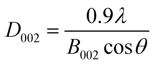
According to the Scherrer's formula, the thickness (D002, nm) of bare g-C3N4 and RuO2 (1.0%)/g-C3N4 composite can be estimated by:
 | (2) |
FTIR spectra of bare g-C3N4 and RuO2 (1.0%)/g-C3N4 composite were determined as shown in Fig. 3.
 | ||
| Fig. 3 FTIR spectra of bare g-C3N4 and RuO2 (1.0%)/g-C3N4 composite. | ||
The peak at 806 cm−1 is originated to the breathing of the heptazine ring system. The absorption bands between 1200 and 1700 cm−1 indicate the presence of C–N heterocycles. The broad peak at 3164 cm−1 was due to the stretching of the terminal N–H from the uncondensed amine.14 FTIR spectra of RuO2/g-C3N4 composite are comparable to those of bare g-C3N4 in the lower wavenumber range. However, the peak intensities of RuO2/g-C3N4 composite were a little weaker than those of bare g-C3N4,15 indicating loss of N–H bond during the preparation of RuO2/g-C3N4 composite.
Representative TEM images of bare g-C3N4 and RuO2 (1.0%)/g-C3N4 composite were presented in Fig. 4a and b respectively.
 | ||
| Fig. 4 TEM images of pure g-C3N4 (left) and RuO2 (1.0%)/g-C3N4 composite (right). | ||
The TEM image of pure g-C3N4 indicated a wrinkled-layer structure along with some stacking layers that have a thin sheet and a typical lamellar morphology. The TEM image of RuO2 (1.0%)/g-C3N4 composite revealed that small RuO2 particles are evenly dispersed on the g-C3N4 surface. The size of RuO2 particles is in the range 10–20 nm. HRTEM images and STEM-EDS mapping of RuO2 (1.0%)/g-C3N4 composite were presented in Fig. S1 and S2,† respectively. It can be clearly observed from Fig. S1† that the lattice fringe of RuO2 was present in the sample. Fig. S2† indicated the distribution of Ru agrees well with those of both dark filed and bright field mapping but differs slightly from that of oxygen, meaning that the oxygen not only comes from RuO2 but also from g-C3N4 (Fig. 5). These results verified that RuO2 is tightly contacted with g-C3N4, forming the RuO2/g-C3N4 heterojuncters.
 | ||
| Fig. 5 XPS survey spectra of g-C3N4 and RuO2 (1.0%)/g-C3N4 (upper), high resolution XPS of RuO2 (1.0%)/g-C3N4 (278–294 eV, middle) and Ru 3d scan of RuO2 (1.0%)/g-C3N4 (lower). | ||
To further identify the chemical structure of g-C3N4 and RuO2/g-C3N4, XPS analyses were performed and given in Fig. 5. The XPS survey spectra of g-C3N4 confirm that g-C3N4 is mainly composed of carbon and nitrogen, with a small amount of oxygen. The existence of oxygen in g-C3N4 is likely due to oxidation during the condensation polymerization. It is noteworthy that the relative intensity of nitrogen peak in g-C3N4 is higher than that in RuO2/g-C3N4. The higher nitrogen content in g-C3N4 can be attributed to the preservation of –NH2 and NH groups. The peaks located at 280.62 eV and 282.53 eV belong to 3d5/2 of RuO2.14 The theoretical peaks of Ru 3d3/2 should be observed at 284.88 eV and 286.78 eV, however as they are partially overlapped with those from C 1s, making it difficult to differentiate them, which is consistent with the results of Hwang et al.17 RuO2 exists in Ru4+ state in RuO2 (1.0%)/g-C3N4, indicating the successful deposition of RuO2 on the g-C3N4 surface.
UV-Vis absorption spectra of the pure g-C3N4 and the RuO2/g-C3N4 composite at various concentrations were illustrated in Fig. 6. It can be observed from Fig. 6 that all of them were capable of visible light absorption. In general, absorption of the RuO2/g-C3N4 composite was stronger than the bare g-C3N4, especially in the visible range. However, the absorption of RuO2/g-C3N4 composite was weaker than bare g-C3N4 in the range 397–434 nm, which is different from those reported earlier.14 Outside the wavelength range, the absorption decreases with increasing RuO2 loading.15,16
 | ||
| Fig. 6 UV-Vis absorption spectra of pure g-C3N4 and RuO2/g-C3N4 composite. | ||
3.2. Photocatalytic reduction of Cr(VI) by g-C3N4 and RuO2/g-C3N4
Variations in Cr(VI) concentration with illumination time in the presence of 0.1 g of pure g-C3N4, pure RuO2 and RuO2 (1.0)/g-C3N4 composite were shown in Fig. 7, respectively. | ||
| Fig. 7 Photocatalytic reductions of Cr(VI) by pure g-C3N4, pure RuO2 and RuO2 (1.0%)/g-C3N4 composite (solution volume, 200 mL; catalyst, 0.1 g; initial Cr(VI) concentration, 0.5 mM; initial pH, 2.3; light source, LED (410 nm, 40 W)). | ||
As seen in Fig. 7, Cr(VI) concentration decreased smoothly with the illumination time. However, the Cr(VI) concentration decreased much more rapidly in the case of RuO2/g-C3N4 composite than pure g-C3N4 or RuO2. After 90 min of illumination, the Cr(VI) removal is ca. 76.4% for RuO2 (1.0%)/g-C3N4 and 33.8% for pure g-C3N4, while it is negligible for pure RuO2 (<5%). The Cr(VI) reduction rate (calculated at the initial stage) with RuO2 (1.0%)/g-C3N4 composite is 4.6 times that of the g-C3N4, which obviously confirms the promoting effect of RuO2 in photocatalytic reduction activity of g-C3N4. It is noted that the Cr(VI) removal is much less when the combination of RuO2 and g-C3N4 was used to reduce Cr(VI), illustrating the successful preparation of heterojunction. In addition, Fig. 7 also showed that the Cr(VI) removal due to adsorption and the direct photolysis were both negligible.18,19 Therefore, the present experiments do not consider the direct photolysis of Cr(VI) in the subsequent experiments. When the illumination time is increased to 150 min, the Cr(VI) is below the detection limit (not shown in the figure) in the case of RuO2 (1.0%)/g-C3N4, which means that Cr(VI) can be totally reduced without any sacrificial electron donor.
3.3. Effect of initial pH on Cr(VI) photocatalytic reduction
The natural pH of the Cr(VI) solution prepared by dissolving K2Cr2O7 in ultrapure water is about 5.5, at which little Cr(VI) reduction was observed under photocatalytic conditions. Therefore, we studied Cr(VI) reduction in acidic medium. Fig. 8 shows Cr(VI) photocatalytic reductions in the presence of 0.1 g RuO2 (1.0%)/g-C3N4 composite under different initial pH (pH0) values. | ||
| Fig. 8 Photocatalytic reduction of Cr(VI) with RuO2 (1.0%)/g-C3N4 under different pH0 values (solution volume, 200 mL; catalyst, 0.1 g; initial Cr(VI) concentration, 0.5 mM; light source, LED (410 nm, 40 W)). | ||
It is demonstrated from Fig. 8 that the Cr(VI) reduction proceeds more rapidly in lower pH0. However, the trend is reversed at pH0 2.4. After 90 min of illumination, the Cr(VI) removal is 40% at pH0 3.0 and increases to 95% at pH0 2.4 and drops to 88% at pH0 2.2. The above phenomena can be explained as follows.
In the present experimental conditions, Cr(VI) exists mainly in the form of dichromate (Cr2O72−) and hydrogen chromate (HCrO4−). Their mutual relations can be described by reactions (3) and (4).20,21
| Cr2O72− + H2O ⇄ 2HCrO4− K3 = 0.22 M | (3) |
| HCrO4− ⇄ CrO42− + H+ K4 = 3.2 × 10⁻⁷ M | (4) |
Over 96% of Cr(VI) is present in the form HCrO4− and ca. 4% is in the form Cr2O72− within pH range 2.0–5.0 at 0.5 mM Cr(VI). As the reaction between HCrO4− and e− is promoted by H+ (reaction (5)), the Cr(VI) reduction rate increases as the solution pH decreases.21
| HCrO4− + e− + H+ → H2CrO4− (Cr(V)) | (5) |
At high concentrations of H+, completing reaction between H+ and e− (reaction (6)) prevails, which leads to less e− available for Cr(VI) reduction. As a result, the Cr(VI) reduction rate decreased with further decreasing pH0:8
| 2H+ + 2e− → H2 | (6) |
On the other hand, when using sulfuric acid to lower the solution pH, hydrogen sulfate ion will be inevitably formed, and it will react with HCrO4− to form CrSO72−, which decreased the effective HCrO4− concentration and the Cr(VI) reduction would slow down in highly acidic condition (eqn (7)):21
| HCrO4− + HSO4− ⇄ CrSO72− + H2O K5 = 0.42 M−1 | (7) |
To further elucidate the pH role in Cr(VI) reduction, variations of solution pH during illumination in the presence and absence of Cr(VI) are presented in Fig. 9.
 | ||
| Fig. 9 Variations of pH during illumination with and without Cr(VI) (solution volume, 200 mL; RuO2 (1.0%)/g-C3N4 composite, 0.1 g; initial Cr(VI) concentration, 0.5 mM; pH0, 2.4; light source, LED (410 nm, 40 W)). | ||
It can be seen from Fig. 9 that the pH of solution containing Cr(VI) increases apparently with illumination time. However, without Cr(VI), pH of the solution changes little. This can be explained by the fact that the Cr(VI) reduction consumes H+, as the overall Cr(VI) reduction stoichiometry can be represented by reactions (8) and (9):
| HCrO4− + 3e− + 7H+ → Cr3+ + 4H2O | (8) |
 | (9) |
Reactions (8) and (9) need the involvement of H+ from the dynamic aspect. As shown in Fig. 8, Cr(VI) reduction proceeded fastest at pH0 2.4, and pH0 2.4 is chosen as the optimum pH in the following investigations.
3.4. Effect of electron and hole scavengers on Cr(VI) reduction
In order to further improve the reduction efficiency of Cr(VI), small amount of organic additives was added to the solution to explore whether the organic solvent will inhibit or promote the reduction of Cr(VI). Fig. 10 shows the Cr(VI) concentration variations in the presence of methanol and acetone, respectively.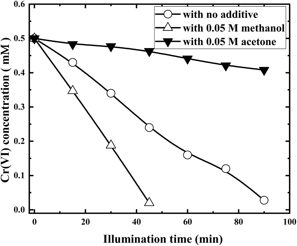 | ||
| Fig. 10 Photocatalytic reductions of Cr(VI) with RuO2 (1.0%)/g-C3N4 in the presence of methanol and acetone (solution volume, 200 mL; RuO2 (1.0%)/g-C3N4 composite, 0.1 g; initial Cr(VI) concentration, 0.5 mM; pH0, 2.4; light source, LED (410 nm, 40 W)). | ||
It is clearly shown from Fig. 10 that acetone suppresses while methanol promotes the Cr(VI) reduction dramatically. Cr(VI) removal rate was more than doubled and three quarters decreased in the presences of 0.05 M methanol and acetone, respectively. The above phenomena can be explained as follows.
Upon illumination, e− and h+ were simultaneously produced. The h+ can re-oxidize the Cr(III) back to Cr(VI) as the oxidation potential of h+ (ca. 1.5 V) is 0.2 V higher than that of Cr(VI) (ca. 1.3 V, reaction (9)). In addition, the h+ can recombine with e− to decrease the number of e− available for Cr(VI) reduction. The most desirable way is to convert the h+ into organic radicals possessing reduction potentials in the range of −1 to −2 V and are thus capable of reducing Cr(VI) to lower oxidation states, which not only inhibits the re-oxidation of Cr(III) and increases the concentration of e−, but also converts the oxidizing h+ to the reducing ones:22
 | (10) |
As reaction (10) goes, more e− are available for Cr(VI) reduction. Consequently, the Cr(VI) reduction rate increased in the presence of methanol. On the other hand, as acetone is very stable and cannot be oxidized by the h+ but can react with e− as the following:23–25
 | (11) |
As reaction (11) involved in the process, less e− is available for Cr(VI) reduction and the Cr(VI) reduction rate decreased in the presence of acetone.
3.5. Effect of Fe(III) on Cr(VI) photocatalytic reduction
Fe(III) is an ubiquitous and nontoxic elements in earth, and investigate its action on photocatalytic reduction of Cr(VI) is of great significance. Fig. 11 compares the Cr(VI) concentration variations in the presence and absence of 0.05 mM Fe(III), respectively. | ||
| Fig. 11 Photocatalytic reductions of Cr(VI) with RuO2 (1.0%)/g-C3N4 in the presence and absence of 0.05 mM Fe(III) (solution volume, 200 mL; RuO2 (1.0%)/g-C3N4 composite, 0.1 g; initial Cr(VI) concentration, 0.5 mM; pH0, 2.4; light source, LED (410 nm, 40 W)). | ||
It can be clearly observed from Fig. 11 that at the initial stage (<20 min), Fe(III) displayed little effect on the reduction of Cr(VI). However, the effect becomes apparent at the later stage. The Cr(VI) removal of Cr(VI) at 75 min can reach 100% with 0.05 mM Fe(III), where it is only 80% without it. When Fe(III) was added, it was reduced to Fe2+ by the e−, and then the resulting Fe2+ reduces Cr(VI) to Cr(III) and next circle begins, which means that Fe(III) can be used as a co-catalyzer.3
| Fe(III) + e− → Fe2+ | (12) |
| 3Fe2+ + Cr(VI) → 3Fe(III) + Cr(III) | (13) |
It is noted that as isopropanol ultimately generated by the reaction (11) cannot reduce Cr(VI), the reduction of Cr(VI) is suppressed. Therefore, although both Fe(III) and acetone belong to electron scavengers, they showed opposing effects on Cr(VI) reductions.
3.6. Mechanism of photocatalytic reduction of Cr(VI) by RuO2/g-C3N4
To elucidate the mechanism in Cr(VI) reduction, evolution of UV-Vis absorption spectra of the solution during photocatalytic reduction are presented in Fig. 12. | ||
| Fig. 12 Evolution of UV-Vis absorption spectra of the solution during photocatalytic reduction of Cr(VI) (solution volume, 200 mL; RuO2 (1.0%)/g-C3N4 composite, 0.1 g; initial Cr(VI) concentration, 0.5 mM; pH0, 2.4; light source, LED (410 nm, 40 W)). | ||
As shown in Fig. 12, the peak height at about 350 nm, which is characteristic of the absorption band of Cr(VI) species,21 together with that at 285 nm, gradually decreases with the illumination time. In general, Cr(VI) would undergo a series of intermediate processes before being finally converted to Cr(III). As shown in Fig. 12, no new bands appeared during the reduction, indicating that the possible Cr(IV) and Cr(IV) were too short-lived to be detected by the present technique.26,27 In the experiment, color of the solution changed from orange to light yellow and finally to colorless, which was verified by the decrease in absorption band from 400 to 450 nm.
According to ref. 14, g-C3N4 and RuO2 are both n-type semiconductors. The values of ECB and EVB for pure g-C3N4 are −1.125 eV and +1.585 eV,28 respectively. ECB and EVB of RuO2 can be calculated according to the formula (14) and (15):29
| ECB = EVB − Eg | (14) |
| EVB = X − Ee + 0.5Eg | (15) |
 | ||
| Fig. 13 Fluorescence emission spectra of g-C3N4 and RuO2 (1.0%)/g-C3N4. | ||
It can be shown in Fig. 13 that the emission intensity of RuO2/g-C3N4 was much lower than g-C3N4, showing the suppressed recombination of photo-carriers.
In addition, the absorption of RuO2/g-C3N4 is slightly weaker than pure g-C3N4 near 410 nm as shown in Fig. 6, indicating that the role of RuO2 belongs to the enhancement of charge separation rather than the enhancement of light absorption, which also indicates that the mechanism speculation is reasonable. The process can be demonstrated in Fig. 14:
 | ||
| Fig. 14 Mechanism of photocatalytic reduction of Cr(VI) by RuO2/g-C3N4. | ||
On the other hand, the loaded RuO2 is able to take up the h+ from g-C3N4, exhibiting functionality as efficient O2 evolution sites. The reaction sequence for O2 evolution can be expressed as follows:30
| RuO2 + 2h+ → RuO22+ | (16) |
| RuO22+ + H2O → RuO3 + 2H+ | (17) |
| 2RuO3 → 2RuO2 + O2(g) | (18) |
In order to confirm the above assumptions, time courses of O2 and N2 evolution during the illumination were examined and the results are presented in Fig. 15.
 | ||
| Fig. 15 Time courses of O2 and N2 evolution during the illumination (solution volume, 200 mL; RuO2 (1.0%)/g-C3N4 composite, 0.1 g; initial Cr(VI) concentration, 0.5 mM; pH0, 2.4; light source, LED (410 nm, 40 W)). | ||
It is demonstrated from Fig. 15 that RuO2 (1.0%)/g-C3N4 composite exhibited high activity for O2 evolution with no N2 evolution. This further indicated that RuO2 loading not only boost the separation of the charge carriers but also protects the decomposition of g-C3N4.
3.7. Recyclability and stability test
To evaluate the reusability and stability of the samples, five successive cycles of experiments were performed for Cr(VI) reduction. After completion of each reduction reaction (90 min), the catalyst in the solution was filtered with 0.22 μm filter membrane, washed with ethanol and water for 3 times respectively, put it into the oven, and bake at 60 °C for 24 hours for the next experiment. Namely, the used sample after each cycle was collected through centrifugation and rinsed three times with ethanol and ultrapure water. Subsequently, the washed powder was dried for 8 h (60 °C) to conduct next photocatalytic cycle. Moreover, the XRD of the samples after six cycles was characterized and compared to that of the fresh samples. A total of 5 cycles were carried out. The reduction ratio of Cr(VI) at each final cycle is shown in Fig. 16. | ||
| Fig. 16 Cycle stability test of RuO2 (1.0%)/g-C3N4 composite (solution volume, 200 mL; RuO2 (1.0%)/g-C3N4 composite, 0.1 g; initial Cr(VI) concentration, 0.5 mM; pH0, 2.4; light source, LED (410 nm, 40 W)). | ||
It can be seen from Fig. 16 that the Cr(VI) reduction ratio with recycled RuO2 (1.0%)/g-C3N4 still maintains more than 80% after five repeated experiments, indicating that the photocatalytic stability of RuO2 (1.0%)/g-C3N4 is still very good and can be reused. ICP-AES test showed no leaching of Ru form RuO2 (1.0%)/g-C3N4. In addition, TOC analysis also showed no apparent carbon and nitrogen increase in the solution, indicating that RuO2 (1.0%)/g-C3N4 is very stable during the photocatalysis.
4. Conclusions
RuO2/g-C3N4 composite can be easily prepared by in situ forced hydrolysis and oxidation and is able to catalytically photo-reduce Cr(VI) effectively even in the absence of sacrificial electron donor. The optimum initial pH for the reduction is 2.4. Acetone inhibits the reduction and methanol promotes the reduction. In addition, a small amount of Fe(III) catalyzes the reduction of Cr(VI), especially in the later stage.The deposited RuO2 particles not only functionalized as an effective charge separator for Cr(VI) reduction, but also protects the g-C3N4 from self-decomposition through catalyzing O2 evolution, which is indispensable for the reduction without presence of electron donors. Little leaching and residue remained in the solution further proves its potential application in real wastewater treatment process.
Data availability
The authors confirm that the data supporting the findings of this study are available within the article.Author contributions
Conceptualization, Y. Liu; methodology, Y. Liu; software, Y. Liu; validation, Y. Liu; formal analysis, Y. Liu; investigation, X. Du and Z. Huang; resources, Y. Liu; data curation, Y. Liu; writing—original draft preparation, Y. Liu; writing—review and editing, Y. Liu; visualization, Y. Liu; supervision, Y. Liu; project administration, Y. Liu; funding acquisition, Y. Liu. All authors have read and agreed to the published version of the manuscript.Conflicts of interest
The authors declare no conflict of interest.Acknowledgements
This research was funded by the National Natural Science Foundation of China grant number [11005014, 11675031] and the APC was funded by [11005014].References
- M. Ding and X. Shi, Molecular mechanisms of Cr(VI)-induced carcinogenesis, Mol. Cell. Biochem., 2002, 234–235, 293–300 CrossRef.
- L. Wang and X. Jiang, Plasma-induced reduction of chromium(VI) in an aqueous solution, Environ. Sci. Technol., 2008, 42(22), 8492–8497 CrossRef CAS.
- L. E. Eary and R. Dhanpat, Chromate removal from aqueous wastes by reduction with ferrous ion, Environ. Sci. Technol., 1988, 22, 972–977 CrossRef CAS PubMed.
- X. Wang, K. Maeda and A. Thomas, et al., A metal-free polymeric photocatalyst for hydrogen production from water under visible light, Nat. Mater., 2009, 8(1), 76–80 CrossRef CAS PubMed.
- W. Wang, Q. Niu and G. Zeng, et al., 1D porous tubular g-C3N4 capture black phosphorus QDs as 1D/0D metal-free photocatalysts for oxytetracycline hydrochloride degradation and hexavalent chromium reduction, Appl. Catal., B, 2020, 273, 119051 CrossRef CAS.
- J. Ren, S. Lv and S. Wang, et al., Construction of efficient g-C3N4/NH2-UiO-66(Zr) heterojunction photocatalysts for wastewater purification, Sep. Purif. Technol., 2021, 274, 118973 CrossRef CAS.
- P. H. Eslamlu, A. H. Yangjeh and S. A. Khaneghah, et al., Integration g-C3N4 nanotubes and Sb2MoO6 nanoparticles: impressive photoactivity for tetracycline degradation, Cr(VI) reduction, and organic dyes removals under visible light, Adv. Powder Technol., 2021, 32, 2322–2335 CrossRef.
- Q. Zhong, H. Lan and M. Zhang, et al., Preparation of heterostructure g-C3N4/ZnO nanorods for high photocatalytic activity on different pollutants (MB, RhB, Cr(VI) and eosin), Ceram. Int., 2020, 46(8), 12192–12199 CrossRef CAS.
- R. M. Mohamed and A. A. Ismail, Mesoporous BiVO4/2D-g-C3N4 heterostructures for superior visible light-driven photocatalytic reduction of Hg(II) ions, Ceram. Int., 2021, 472, 26063–26073 CrossRef.
- K. Maeda, X. Wang and Y. Nishihara, et al., Photocatalytic activities of graphitic carbon nitride powder for water reduction and oxidation under visible light, J. Phys. Chem. C, 2009, 113(12), 4940–4947 CrossRef CAS.
- T. P. Luxton, M. J. Eick and K. G. Scheckel, Characterization and dissolution properties of ruthenium oxides, J. Colloid Interface Sci., 2011, 359(1), 30–39 CrossRef CAS PubMed.
- Y. Lee, J. Suntivich and K. J. May, et al., Synthesis and activities of rutile IrO2 and RuO2 nanoparticles for oxygen evolution in acid and alkaline solutions, J. Phys. Chem. Lett., 2012, 3(3), 399–404 CrossRef CAS PubMed.
- K. Kalyanasundaram and M. Grtzel, Cyclic cleavage of water into H2 and O2 by visible light with coupled redox catalysts, Angew. Chem., Int. Ed., 1979, 18(9), 701–702 CrossRef.
- L. A. Al-Hajji, F. M. Alshareef and A. A. Ismail, et al., RuO2 nanoparticles-accommodated graphitic carbon nitride for significant enhancement in photocatalytic oxidation of trichloroethylene, Opt. Mater., 2022, 125, 112086 CrossRef CAS.
- B. Li, K. Nie, Y. Zhang, L. Yi, Y. Yuan, S. Chong, Z. Liu and W. Huang, Engineering single-layer hollow structure of transition metal dichalcogenides with high 1T-phase purity for hydrogen evolution reaction, Adv. Mater., 2023, 35(46), 2303285 CrossRef CAS PubMed.
- Z. Liu, K. Nie, X. Qu, X. Li, B. Li, Y. Yuan, S. Chong, P. Liu, Y. Li, Z. Yin and W. Huang, General bottom-up colloidal synthesis of nano-monolayer transition-metal dichalcogenides with high 1T′-phase purity, J. Am. Chem. Soc., 2022, 144, 4863–4873 CrossRef CAS.
- J. Y. Hwang, M. F. El-Kady and Y. Wang, Direct preparation and processing of graphene/RuO2 nanocomposite electrodes for high-performance capacitive energy storage, Nano Energy, 2015, 18, 57–70 CrossRef CAS.
- P. Niu, L. Zhang and G. Liu, et al., Graphene-like carbon nitride nanosheets for improved photocatalytic activities, Adv. Funct. Mater., 2012, 22(22), 4763–4770 CrossRef CAS.
- H. Sun and Y. Liu, Efficient Adsorption of Azo Dye Acid Brilliant Red on Graphite Carbon Nitride in Aqueous Solution, ACS Omega, 2024, 9, 28626–28636 CrossRef CAS.
- J. Y. Tong and E. L. King, A spectrophotometric investigation of the equilibria existing in acidic solutions of chromium(VI), J. Am. Chem. Soc., 1953, 75(24), 6180–6186 CrossRef CAS.
- G. P. Haight Jr, D. C. Richardson and N. H. Coburn, A spectrophotometric study of equilibria involving mononuclear chromium(VI) species in solutions of various acids, Inorg. Chem., 1964, 3(12), 1777–1780 CrossRef.
- Y. Shiraishi, S. Kanazawa and Y. Sugano, et al., Highly selective production of hydrogen peroxide on graphitic carbon nitride (g-C3N4) photocatalyst activated by visible light, ACS Catal., 2014, 4(3), 774–780 CrossRef CAS.
- Y. Maham and G. R. Freeman, Effect of solvent structure on electron reactivity: 2-propanol/water mixtures, Can. J. Chem., 1988, 66, 1706–1711 CrossRef CAS.
- C. D. Jonah, J. R. Miller and M. S. Matheson, The reaction of the precursor of the hydrated electron with electron scavengers, J. Phys. Chem., 1977, 81, 1618–1622 CrossRef CAS.
- A. M. El-Nahas, J. W. Bozzelli, J. M. Simmie, M. V. Navarro, G. Black and H. J. Curran, Thermochemistry of acetonyl and related radicals, J. Phys. Chem. A, 2006, 110(50), 13618–13623 CrossRef CAS PubMed.
- G. V. Buxton and F. Djouider, Disproportionation of CrV generated by the radiation-induced reduction of CrVI in aqueous solution containing formate: a pulse radiolysis study, J. Chem. Soc., Faraday Trans., 1996, 92(21), 4173–4176 RSC.
- G. V. Buxton, F. Djouider and D. A. Lynch, et al., Oxidation of CrIII to CrVI initiated by OH and SO4− in acidic aqueous solution A pulse radiolysis study, J. Chem. Soc., Faraday Trans., 1997, 93(24), 4265–4268 RSC.
- P. Praus, On electronegativity of graphitic carbon nitride, Carbon, 2021, 172, 729–732 CrossRef CAS.
- R. G. Pearson, Absolute electronegativity and hardness: application to inorganic chemistry, Inorg. Chem., 1988, 27(4), 734–740 CrossRef CAS.
- S. Barison, D. Barreca and S. Daolio, et al., Influence of electrochemical processing on the composition and microstructure of chemical-vapor deposited Ru and RuO2 nanocrystalline films, J. Mater. Chem., 2002, 12(5), 1511–1518 RSC.
Footnote |
| † Electronic supplementary information (ESI) available. See DOI: https://doi.org/10.1039/d5ra00883b |
| This journal is © The Royal Society of Chemistry 2025 |