DOI:
10.1039/D4RA09025J
(Paper)
RSC Adv., 2025,
15, 6400-6412
Enhanced photocatalytic degradation of malachite green and trypan blue using 3-aminopropyl triethoxysilane (APTES) functionalized iron oxide nanocomposite†
Received
26th December 2024
, Accepted 14th February 2025
First published on 26th February 2025
Abstract
Biochar-capped iron oxide nanoparticle functionalized with 3-aminopropyl triethoxysilane (APTES) was synthesized and used as photocatalysts for the degradation of malachite green (MG) and trypan blue (TPB) dyes. Powder X-ray diffraction patterns confirmed the crystalline cubic spinel structure of Fe3O4. HRTEM image shows nanocomposites with an average particle size of 22.4 nm, interplanar spacings of 0.297 nm and 0.245 nm, which correspond to the (220) and (222) planes of Fe3O4. SAED patterns indicate that Fe3O4@BC/APTES nanocomposite is polycrystalline. The energy bandgap of the biochar-capped iron oxide nanoparticles was reduced from 3.47 to 2.85 eV after functionalization with APTES. Photocatalytic degradation potential of the nanocomposite was evaluated with malachite green (MG) and trypan blue (TPB) dyes using the response surface methodology based on the Box–Behnken design (RSM-BDD). The optimal degradation efficiency from RSM-BBD for MG was 99.94% with a catalyst dosage of 7.5 mg, dye concentration of 50 ppm, and pH of 9 for 105 min. The optimum parameters for TPB were found to be a concentration of 30 ppm, a catalyst dosage of 12 mg, a pH of 5, and 85.77% of degradation after 90 min. Reusability studies show that the nanocomposite can be reused five times without significant reduction in the photocatalytic degradation efficiency.
1. Introduction
Azo is a broad category of artificial organic dyes containing one or more azo groups (–N![[double bond, length as m-dash]](https://www.rsc.org/images/entities/char_e001.gif) N). These are the dyes commonly used in the textile, paper, leather, food, and cosmetics industries.1,2 Some of these dyes are discharged into the environment via sewage. The presence of azo dyes can lead to significant environmental damage due to their extremely stable and complex chemical structures that are resistant to degradation processes.3 Their prolonged presence could cause irreversible detrimental impacts on human health, the environment, and endanger aquatic ecosystems because of their toxic and non-biodegradable nature.4–6 Consequently, it is imperative that these contaminants are eliminated from human water sources and wastewater from industries. Photocatalysis has drawn much interest among several physical and chemical contaminant removal techniques because of its high efficiency, simplicity, and cost-effectiveness.7–9
N). These are the dyes commonly used in the textile, paper, leather, food, and cosmetics industries.1,2 Some of these dyes are discharged into the environment via sewage. The presence of azo dyes can lead to significant environmental damage due to their extremely stable and complex chemical structures that are resistant to degradation processes.3 Their prolonged presence could cause irreversible detrimental impacts on human health, the environment, and endanger aquatic ecosystems because of their toxic and non-biodegradable nature.4–6 Consequently, it is imperative that these contaminants are eliminated from human water sources and wastewater from industries. Photocatalysis has drawn much interest among several physical and chemical contaminant removal techniques because of its high efficiency, simplicity, and cost-effectiveness.7–9
Recently, there has been increased interest in magnetic nanoparticles, especially iron oxide, because of their unique magnetic properties, low toxicity, biocompatibility, and simple, cost-effective fabrication process.10–13 Furthermore, iron oxide-based nanomaterials have been identified as potentially useful materials for remediation of polluted wastewater because of their high activity, and ease of recovery by an external magnetic field. However, magnetic iron oxide nanoparticles have inherent disadvantages, such as poor stability under high temperatures and aggregation of particles due to dipole–dipole moments, which reduces their surface area and reactive activities.14–16 Bio-nanocomposite synthesis is thus a practical approach to improve the stability of magnetic nanoparticles and prevent them from oxidation.
In order to enhance the biocompatibility and stability of metal oxide nanoparticles such as iron oxides nanoparticles, they are being functionalization with silica,17,18 natural compounds,19,20 polymers,21,22 and organic layers.23,24 This significantly broadens the range of potential applications. One of the compounds for surface modification that is frequently utilized among these coating agents is silica. Silica coating also improves their stability, and create a novel medium for additional functionalization.25,26 It creates a thick coating on magnetic nanoparticles, and provides protection against oxidation. To obtain desired properties, silanol functional groups can also be employed to further functionalize magnetic nanoparticles with other biomolecules and polymers. As a result, the silanol groups on the surface of nanoparticles facilitate the ease of immobilization of the hydroxyl groups that are present in natural biomolecules like flavonoids.27
Biochar has been demonstrated to be an effective capping agent due to its porous nature, stability and large surface area.28,29 Biochar-capped nanocomposites may facilitate the separation of photogenerated carriers and are not prone to corrosion.30 In this study, we present the use of Portulacaria afra biochar-capped iron oxide nanocomposite coated with tetraethyl orthosilicate (TEOS) and functionalized with (3-aminopropyl)triethoxysilane (APTES), [Fe3O4@BC/APTES] and its use as photocatalyst for the degradation of cationic dyes, malachite green and trypan blue. The kinetics, effect of pH, and scavengers on the degradation of the dyes are also evaluated.
2. Materials and methodology
2.1 Materials
Materials used for the preparation of the magnetic iron oxide nanocomposites are Fe2(SO4)3·H2O, FeCl2·4H2O, 25% ammonia solution, P. afra biochar, tetraethyl orthosilicate (TEOS), toluene, ethanol and (3-aminopropyl)triethoxysilane (APTES). The dyes used for the photocatalytic study are malachite green and trypan blue. Scavengers, formic acid, benzoquinone, tert-butyl alcohol and potassium nitrate. The pH was adjusted using HCl and NaOH. All materials were used as received. HRTEM images were captured on JEOL JEM2100 Transmission electron microscope. ImageJ software was used to measure particle sizes. The phase identification of the iron oxide nanocomposite was conducted using powder X-ray diffraction (XRD) on a Bruker D8 instrument (Billerica, MA, USA) equipped with monochromatic CuKα radiation, over a 2θ range of 10° to 90°. FTIR (Cary 100) and PerkinElmer lambda 25 UV-Vis spectrophotometer were used in the qualitative analysis of the magnetic nanoparticles and composite. The dye degradation experiments were carried out under a 70 W high-pressure mercury lamp. The pH was monitored using Metrohm 827 pH meter.
2.2 Methods
2.2.1 Preparation of Portulacaria afra biochar. Dried Portulacaria afra leaves (30 g) were placed in a porcelain crucible and carbonized for 3 h at 300 °C in a vacuum tube furnace. The resulting P. afra biochar was powdered using a pestle and mortar.
2.2.2 Preparation of Fe3O4@BC. Iron oxide nanoparticles were prepared by co-precipitation method.31 Fe2(SO4)3·H2O (0.005 mol, 2.0895 g) and FeCl2·4H2O (0.0025 mol, 0.4970 g) were dissolved in 50 mL of distilled water in 3-neck round bottom flask. The salts solution was heated to 90 °C under nitrogen and 15 mL of 25% ammonia solution was added and the mixture was stirred for 1 h. 2 g of biochar was added and the resultant mixture was stirred for 6 h. The biochar capped nanocomposite was washed with distilled water and ethanol then dried in the oven at 80 °C for 12 h.
2.2.3 Preparation of Fe3O4@BC/SiO2 nanoparticles. Fe3O4@BC/SiO2 nanoparticles were prepared using Stöber method.32 1 g of biochar-capped iron oxide nanoparticles were dispersed in 80 mL ethanol by continuous stirring at 40 °C. 25 mL of 25% ammonia solution was added to the mixture after 30 min. Thereafter, 2 mL TEOS was introduced with the mixture and was left to stir for 24 h at 40 °C under nitrogen. Finally, the product was separated by an external magnet and rinsed with distilled water and ethanol then dried in the oven at 60 °C for 12 h.
2.2.4 Preparation of Fe3O4@BC/APTES nanoparticles. Fe3O4@BC/APTES composite was prepared using the reported method.33 2 mL APTES was added into a mixture of Fe3O4@BC-SiO2 NPs (1 g) and 30 mL toluene under continuous stirring for 12 h at 80 °C under nitrogen atmosphere. The obtained Fe3O4@BC/APTES composite was separated by an external magnet then washed with ethanol and dried for 12 h at 50 °C in the oven.
2.2.5 Point of zero charge (pHzpc)test. The pHzpc test for Fe3O4@BC/APTES nanocomposite was carried out with a 0.01 M NaCl solution at a pH of 2 to 10.34 The pH of the solutions varied using 0.1 M HCl and 0.1 M NaOH. 0.02 g of nanocomposite was added to 50 mL of each solution and then placed in a shaker for 24 h at ambient temperature. The filtrate pH readings were taken. The pHzpc value was obtained by plotting the initial solution pH and the change in pH.
2.2.6 Photocatalytic experiment. Photocatalytic activity of the Fe3O4@BC/APTES nanocomposite was carried out using 10–50 ppm trypan blue (TPB) and malachite green (MG). 2.5–12.50 mg of the nanocomposite was dispersed in 6 mL of the dye solution and sonicated for 30 min followed by stirring for 60 min in the dark to reach adsorption–desorption equilibrium. The catalyst-dye mixture was irradiated with OSRAM VIALOX 70 W incandescent mercury lamp for 180 min under continuous stirring. UV-Vis spectra for the solutions after light irradiation were obtained to study the photodegradation of the dyes. The pH of the dyes was adjusted by the addition of 0.1 M HCl or 0.1 M NaOH solution. The study examined the impact of various variables, including dye concentration, time, solution pH, and catalyst dosage, on dye photodegradation efficiency using the RSM/BBD model.
2.2.7 Recycling experiments. The degradation of crystal violet and malachite green by Fe3O4@BC/APTES was repeated in 5 cycles. After each photocatalytic cycle, the catalyst was isolated by a magnet, rinsed with water and ethanol, and then dried in the oven at 80 °C for 2 h.
2.2.8 Experimental variables for Box–Behnken design (BBD) design. Experimental variables used for the study are presented in Table 1 showing the influence of four independent parameters on the dye photodegradation. These parameters are catalyst dosage (mg), time (min), dye concentration (ppm), and solution pH. Each variable was evaluated at three levels: low (−1), midrange (0), and high (+1). Table 2 shows the 4-factor Box–Behnken design (BBD) for all 29 runs, as well as the experimental and estimated results.
Table 1 Experimental variables and their levels
| Factor |
Variables |
Unit |
Level 1 (−1) |
Level 2 (0) |
Level 3 (+1) |
| A |
Time |
min |
30 |
105 |
180 |
| B |
Catalyst dosage |
mg |
2.5 |
7.5 |
12.50 |
| C |
Dye concentration |
ppm |
10 |
30 |
50 |
| D |
pH |
|
3 |
6 |
9 |
Table 2 Experimental design matrix and response results for malachite green (MG) and trypan blue (TPB)
| Run |
Time (min) |
Catalyst dosage (mg) |
Dye concentration (ppm) |
pH |
Malachite green (MG) |
Trypan blue (TPB) |
| Predicted |
Experimental |
Predicted |
Experimental |
| 1 |
105 |
7.5 |
10 |
3 |
93.11 |
95.77 |
73.22 |
73.46 |
| 2 |
180 |
2.5 |
30 |
6 |
83.97 |
85.07 |
53.77 |
54.23 |
| 3 |
30 |
7.5 |
50 |
6 |
83.51 |
83.01 |
54.71 |
54.26 |
| 4 |
30 |
2.5 |
30 |
6 |
79.40 |
80.87 |
44.95 |
46.51 |
| 5 |
105 |
7.5 |
10 |
9 |
94.07 |
95.81 |
37.64 |
36.71 |
| 6 |
105 |
7.5 |
50 |
3 |
66.55 |
66.70 |
54.79 |
54.61 |
| 7 |
180 |
7.5 |
50 |
6 |
88.55 |
87.53 |
45.07 |
45.25 |
| 8 |
105 |
2.5 |
30 |
3 |
55.06 |
53.12 |
52.62 |
51.98 |
| 9 |
105 |
2.5 |
50 |
6 |
76.75 |
78.58 |
27.32 |
27.04 |
| 10 |
180 |
7.5 |
10 |
6 |
98.91 |
96.10 |
79.74 |
80.99 |
| 11 |
180 |
7.5 |
30 |
9 |
95.63 |
98.06 |
37.03 |
37.34 |
| 12 |
105 |
7.5 |
30 |
6 |
90.05 |
90.05 |
78.16 |
78.16 |
| 13 |
105 |
12.5 |
30 |
9 |
86.39 |
85.02 |
44.95 |
46.40 |
| 14 |
105 |
12.5 |
50 |
6 |
91.19 |
91.49 |
68.33 |
70.41 |
| 15 |
105 |
7.5 |
30 |
6 |
90.05 |
90.05 |
78.16 |
78.16 |
| 16 |
105 |
7.5 |
50 |
9 |
100.08 |
100.00 |
23.44 |
22.09 |
| 17 |
105 |
7.5 |
30 |
6 |
90.05 |
90.05 |
78.16 |
78.16 |
| 18 |
105 |
7.5 |
30 |
6 |
90.05 |
90.05 |
78.16 |
78.16 |
| 19 |
30 |
12.5 |
30 |
6 |
92.24 |
93.03 |
70.85 |
69.28 |
| 20 |
105 |
2.5 |
10 |
6 |
87.37 |
88.48 |
58.85 |
57.08 |
| 21 |
105 |
12.5 |
30 |
3 |
99.73 |
100.00 |
83.82 |
83.94 |
| 22 |
30 |
7.5 |
30 |
3 |
72.57 |
71.56 |
61.78 |
61.78 |
| 23 |
30 |
7.5 |
30 |
9 |
98.46 |
100.00 |
36.59 |
36.43 |
| 24 |
105 |
2.5 |
30 |
9 |
100.06 |
100.00 |
24.55 |
25.23 |
| 25 |
180 |
12.5 |
30 |
6 |
98.62 |
99.05 |
79.47 |
76.80 |
| 26 |
105 |
7.5 |
30 |
6 |
90.05 |
90.05 |
78.16 |
78.16 |
| 27 |
180 |
7.5 |
30 |
3 |
86.35 |
86.22 |
78.78 |
79.25 |
| 28 |
30 |
7.5 |
10 |
6 |
93.01 |
90.72 |
52.67 |
53.30 |
| 29 |
105 |
12.5 |
10 |
6 |
100.14 |
100.00 |
69.43 |
70.02 |
3. Results and discussion
3.1 Structural and morphological properties of the nanocomposite
The powder XRD patterns of the nanocomposite is shown in Fig. 1(a). The diffractogram displays a broad peak within the 2θ range of 20.18° to 33.31°, which is attributed to the presence of amorphous carbon and silica.35 The sharp peaks indicated by asterisks represent crystalline silica phases embedded in the amorphous biochar.36 The diffraction peaks observed at 17.57°, 35.17°, 41.54°, 44.65°, 50.78°, 63.29°, 67.60°, and 74.52° correspond to the (111), (220), (311), (222), (400), (422), (511), and (400) planes of the crystalline cubic spinel structure of Fe3O4 (PDF ref. 03-065-3107).37 The sharp peaks indicate the high crystallinity of the nanocomposite.
 |
| | Fig. 1 P-XRD patterns of Fe3O4@BC/APTES nanocomposite (*amorphous carbon and silica). | |
The HRTEM images, lattice fringes, and SAED patterns of the nanocomposite are presented in Fig. S1.† The HRTEM image shows mixtures of square-like, quasi-spherical and irregularly shaped particles with an average size of 22.4 nm (Fig. S1(a)†). The lattice fringes shows two interplanar spacings of 0.297 nm and 0.245 nm, which correspond to the (220) and (222) plane of Fe3O4. The ring-shaped SAED patterns (Fig. S1(c)†) indicate that Fe3O4@BC/APTES nanocomposite is polycrystalline.
The average particle size increased after coating with TEOS and functionalization with APTES due to the silica shell and amino groups on the surface of the iron oxide nanoparticles (Fig. S2†). A similar occurrence has been reported where the Fe3O4@SiO2 nanocomposite exhibited a notable increase in particle size and surface area after functionalization with APTES.38 This is mainly due to the formation of the cross-linked silane networks on the nanoparticle surface.
The FT-IR spectra of BC, Fe3O4@BC and Fe3O4@BC/APTES nanocomposite are shown in Fig. S3.† The Fe–O bond is observed at 553 cm−1 in the BC-coated nanoparticles,39 whereas for the Fe3O4@BC/APTES, it is observed at 556 cm−1. The peak at 783 cm−1 is assigned to the Si–O–Fe bond.40 Fe3O4@BC/APTES spectrum shows a peak at 1071 cm−1 attributed to Si–O–Si bands stretching vibration indicating the presence of silica on the surface of the iron oxide nanoparticles.41 The two broad peaks around 3364 cm−1 and 1610 cm−1 correspond to the –OH group on the surface of the as-prepared iron oxide nanocomposite. Fe3O4@BC/APTES spectrum also exhibits two weak absorption bands at 2942 and 2990 cm−1, which are due to the symmetric and asymmetric stretching of the C–H bonds of the propyl groups.
The X-ray fluorescence (XRF) analysis of the Fe3O4@BC/APTES composite reveals its elemental composition in terms of oxides as shown in Table 3. The composite is primarily composed of silica (SiO2), hematite (Fe2O3) obtained from the oxidation of magnetite (Fe3O4) during XRF analysis,42 and a substantial organic/volatile component (L.O.I.), with minor contributions from calcium oxide, magnesium oxide, and other trace elements. These oxides may be trace components derived from the biochar used in the composite. The CHN analysis (Table S1†) provides insight into the organic composition of the Fe3O4@BC/APTES composite. The presence of nitrogen confirms successful functionalization with amino (–NH2) groups. The high carbon content reflects the biochar (BC) component, which is an organic, carbon-rich material. The CHN and XRF analysis show that the material is a hybrid composite, with significant organic materials (generated from biochar and functional groups) and inorganic components like silica and iron oxide.
Table 3 XRF analysis of Fe3O4@BC/APTES composite
| Component |
Weight (%) |
| Al2O3 |
bdl |
| CaO |
1.62 |
| Cr2O3 |
bdl |
| Fe2O3 |
18.89 |
| K2O |
0.04 |
| MgO |
1.42 |
| MnO |
0.05 |
| Na2O |
0.03 |
| P2O5 |
0.25 |
| SiO2 |
29.66 |
| TiO2 |
0.06 |
| L.O.I. |
47.55 |
3.2 Optical properties
The band gap energy indicates the catalyst's potential to harvest light energy which is required for moving an electron from the valence to the conduction band. The Fe3O4@BC/APTES composite absorbs at 286 nm (Fig. 2(a)). The energy band gap of the nanocomposite was determined using the Tauc plot as shown in Fig. 2(b).43 The estimated bandgap value of Fe3O4@BC/APTES was 2.85 eV which is a significant decrease compared to 3.47 eV obtained for Fe3O4@BC/APTES (Fig. S4†). This demonstrates that functionalization of the nanoparticles with APTES can enhance their light response.
 |
| | Fig. 2 Absorption spectrum and Tauc plot of Fe3O4@BC/APTES. | |
3.3 Surface properties
The point of zero charge (pHzpc) is a significant parameter for understanding catalyst activity in solution. The pHzpc value of the Fe3O4@BC/APTES nanocomposite was determined using the plot in Fig. 3 and was found to be 4.51. This suggests that the surface charge of the catalyst will be positive at pH values below pHzpc allowing adsorption of anions. Contrarily, at pH above the pHzpc value, the surface charge will be negative, allowing the adsorption of cations.
 |
| | Fig. 3 Determination of pHzpc value of Fe3O4@BC/APTES. | |
4. Box–Behnken model
4.1 Model fitting and statistical analysis
To assess the effect of specified critical variables on the degradation of MG and TPB dyes on Fe3O4@BC/APTES, two second-order polynomial quadratic equations were statistically generated with RSM-BBD based on the observed data collected from the experiments. The RSM-BBD model coded equations that have been fitted for the decomposition of MG dye and TPB dye are provided in eqn (1) and (2), respectively.
For Malachite green
| | |
D (%) = +90.05 + 2.74 × A + 6.87 × B − 4.96 × C + 8.79 × D + 0.4550 × AB − 0.2150 × AC − 4.15 × AD + 0.3475 × BC − 15.47 × BD +8.31 × CD + 0.2863 × A2 − 1.78 × B2 + 0.6575 × C2 − 2.08 × D2
| (1) |
For Trypan blue
| | |
D (%) = 78.16 + 4.36 A + 12.90 B − 8.16 C − 16.74 D − 0.0500 AB − 9.17 AC − 4.14 AD + 7.61 BC − 2.70 BD + 1.06 CD − 6.92 A2 − 8.98 B2 − 13.19 C2 − 17.69 D2
| (2) |
where
D is the response (degradation efficiency), 90.05 and 78.16 are MG and TPB intercept, respectively.
A,
B, and
C denote regression coefficients for linear effects while AB, AC, AD, BC, BD and CD are regression coefficients for two-factor interaction effects, and
A2,
B2,
C2 and
D2 are for quadratic effects. This equation can be used to estimate the reaction for specific values of each component.
The ANOVA results in Tables 4 and 5 demonstrate the statistical applicability of the established model equations for MG and TPB degradation, with a low p-value (<0.0001) and good precision values (>4) suggesting that the model terms are significant. This means adjusting any model term influences the degradation efficiency of the dye. Moreover, the estimation of correlation (R2) values (>0.95) for both MG and TPB dyes revealed that less than 1% of the total changes in MG and TPB degradation efficiencies did not match the proposed model. The strong adjusted R2 values show that RSM-BBD models have greater potential to predict the photodegradation reaction of MG and TPB. The difference between the adjusted correlation coefficient and expected correlation is less than 0.2, which indicates that experimental and statistically estimated responses are consistent (Tables 4 and 5).44
Table 4 ANOVA results of quadratic model for MG degradation
| Source |
Sum of squares |
df |
Mean square |
F-value |
p-value |
| Model |
3239.75 |
14 |
231.41 |
52.28 |
<0.0001 |
| A-time |
89.87 |
1 |
89.87 |
20.30 |
0.0005 |
| B-catalyst dosage |
566.78 |
1 |
566.78 |
128.05 |
<0.0001 |
| C-dye concentration |
295.72 |
1 |
295.72 |
66.81 |
<0.0001 |
| D-pH |
927.87 |
1 |
927.87 |
209.64 |
<0.0001 |
| AB |
0.8281 |
1 |
0.8281 |
0.1871 |
0.6719 |
| AC |
0.1849 |
1 |
0.1849 |
0.0418 |
0.8410 |
| AD |
68.89 |
1 |
68.89 |
15.56 |
0.0015 |
| BC |
0.4830 |
1 |
0.4830 |
0.1091 |
0.7460 |
| BD |
956.66 |
1 |
956.66 |
216.14 |
<0.0001 |
| CD |
276.56 |
1 |
276.56 |
62.48 |
<0.0001 |
| A2 |
0.5315 |
1 |
0.5315 |
0.1201 |
0.7341 |
| B2 |
20.49 |
1 |
20.49 |
4.63 |
0.0494 |
| C2 |
2.80 |
1 |
2.80 |
0.6335 |
0.4393 |
| D2 |
28.16 |
1 |
28.16 |
6.36 |
0.0244 |
| Residual |
61.97 |
14 |
4.43 |
|
|
| Lack of fit |
61.97 |
10 |
6.20 |
|
|
| Pure error |
0.0000 |
4 |
0.0000 |
|
|
| Cor total |
3301.72 |
28 |
|
|
|
Table 5 ANOVA results of quadratic model for TPB degradation
| Source |
Sum of squares |
df |
Mean square |
F-value |
p-value |
| Model |
9865.96 |
14 |
704.71 |
347.63 |
<0.0001 |
| A-time |
227.94 |
1 |
227.94 |
112.44 |
<0.0001 |
| B-catalyst dosage |
1996.40 |
1 |
1996.40 |
984.83 |
<0.0001 |
| C-dye concentration |
798.70 |
1 |
798.70 |
394.00 |
<0.0001 |
| D-pH |
3360.72 |
1 |
3360.72 |
1657.85 |
<0.0001 |
| AB |
0.0100 |
1 |
0.0100 |
0.0049 |
0.9450 |
| AC |
336.72 |
1 |
336.72 |
166.11 |
<0.0001 |
| AD |
68.56 |
1 |
68.56 |
33.82 |
<0.0001 |
| BC |
231.50 |
1 |
231.50 |
114.20 |
<0.0001 |
| BD |
29.11 |
1 |
29.11 |
14.36 |
0.0020 |
| CD |
4.47 |
1 |
4.47 |
2.21 |
0.1596 |
| A2 |
310.50 |
1 |
310.50 |
153.17 |
<0.0001 |
| B2 |
523.22 |
1 |
523.22 |
258.10 |
<0.0001 |
| C2 |
1129.14 |
1 |
1129.14 |
557.00 |
<0.0001 |
| D2 |
2030.72 |
1 |
2030.72 |
1001.75 |
<0.0001 |
| Residual |
28.38 |
14 |
2.03 |
|
|
| Lack of fit |
28.38 |
10 |
2.84 |
|
|
| Pure error |
0.0000 |
4 |
0.0000 |
|
|
| Cor total |
9894.34 |
28 |
|
|
|
In addition, the p-values for lack-of-fit showed that the lack-of-fit is significant, indicating that the designed models fit the real data for both MG and TPB dyes.45 Fig. 4 shows the distribution of experimental results versus expected values for the degradation efficiencies of MG and TPB dyes. Evidently, every point was distributed with a small variance along the center line, which indicates that the developed quadratic models fit the data adequately. Thus, the developed models to estimate MG and TPB dye degradation were determined to be appropriate. Model terms were evaluated for significance at a 95% confidence level (p-value < 0.05).
 |
| | Fig. 4 The predicted versus actual plots of (a) MG and (b) TPB photocatalytic degradation. | |
4.2 Response surface analysis
Three-dimensional response surface graphs demonstrate how adjusting two separate variables within the experimental range can influence dye degradation while holding other variables constant. Fig. 5(a) shows that as the dosage of the nanocomposite is increased from 2.5 to 12.5 mg, the degradation efficiency of MG increased to the maximum of 99.05%. The increase in photodegradation efficiency is attributed to more active sites available for the binding of dye molecules, which improves the degradation of the dye.46 TPB degradation efficiency also increases from 54.23% to 83.47% at 2.5 mg to 11 mg (Fig. 6(a)). However, a further increase of catalyst dosage to 12.5 mg decreased the efficiency to 76.80%. This may be due to agglomeration of the composite in solution which hinders the absorption of photons by the catalyst and decreases the number of active surface sites that can interact with the dye molecules.47 In Fig. 6(b), the photocatalytic degradation efficiency of TPB significantly decreased as dye concentration increased due to competition among dye molecules for the photocatalyst active sites.48 A decrease of only 8.57% was observed for MG suggesting that the initial dye concentration does not have a major influence (Fig. 5(c)). Furthermore, it was found that pH 3 is appropriate for the degradation of TPB dye (Fig. 6(e)), whereas MG high degradation efficiencies of 86.22% and 98.06% were obtained at pH 3 and pH 9 (Fig. 5(e)). The high degradation efficiency observed over the broad pH range is attributed to the structural changes of malachite green transforming into carbinol base under alkaline conditions and leucomalachite green under acidic conditions.49,50 This suggests that the composite can degrade MG in a wide range of pH whereas electrostatic interactions are involved in the degradation of TPB. This is because TPB contains stable sulfonic groups which are strong acids, maintaining a negative charge of the dye molecule over a wide pH range.48 This can be further clarified by the composite's point of zero charge of 4.51. At pH < 4.51, the catalyst surface had a positive charge, attracting the anionic TPB, and at pH > 4.51, the catalyst surface had a negative charge, repelling the anionic TPB.
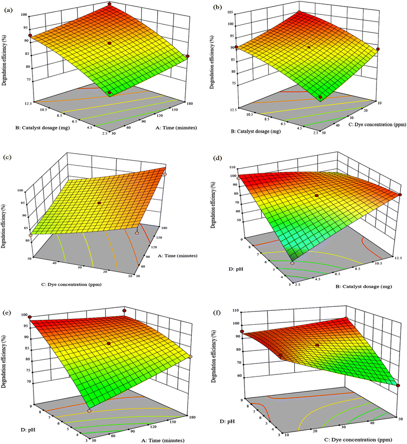 |
| | Fig. 5 Response surface plots for photodegradation efficiency of MG as a function of (a) time vs. catalyst dosage (pH 6, dye concentration = 30 ppm), (b) catalyst dosage vs. dye concentration (time = 105 min, pH 6) (c) time and dye concentration (pH 6, catalyst dosage = 7.5 mg), (d) catalyst dosage vs. pH (time = 105 min, dye concentration = 30 ppm), (e) time vs. pH (catalyst dosage = 7.5 mg, dye concentration = 30 ppm) and (f) dye concentration vs. pH (time = 105 min, catalyst dosage = 7.5 mg). | |
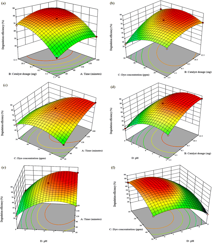 |
| | Fig. 6 Response surface plots for photodegradation efficiency of TPB as a function of (a) time vs. catalyst dosage (pH 6, dye concentration = 30 ppm), (b) time and dye concentration (pH 6, catalyst dosage = 7.5 mg), (c) catalyst dosage vs. dye concentration (time = 105 min, pH 6), (d) catalyst dosage vs. pH (time = 105 min, dye concentration = 30 ppm), (e) time vs. pH (catalyst dosage = 7.5 mg, dye concentration = 30 ppm) and (f) dye concentration vs. pH (time = 105 min, catalyst dosage = 7.5 mg). | |
The degradation efficiency decreased with increasing dye concentration but increased dramatically with increasing catalyst dosage reaching 100% and 70.02% for MG and TPB after 105 min at 10 ppm using 12.5 mg. The negative effect of dye concentration can be attributed to the fact that as the initial concentration of organic dye increases, a greater number of molecules accumulate on the surface of the catalyst causing light shielding effects, thereby inhibiting the photogeneration of reactive species due to active site overloading.51 Fig. 5(f) depicts the relationship between the effect of dye concentration and pH in the experimental ranges on MG degradation efficiency at a catalyst dosage of 7.5 mg and a reaction duration of 180 minutes. It is evident that the optimum degradation efficiency for MG occurs at pH 9 in 50 ppm. In contrast, TPB degradation is enhanced at pH 3 with a maximum efficiency of 73.46% at 10 ppm (Fig. 6(f)). This suggests that TPB degradation is more dependent on initial dye concentration than MG. The decrease in degradation efficiency at higher TPB concentrations highlights a critical limitation for photocatalytic processes in treating highly concentrated dye wastewater on an industrial scale. Addressing this issue would require optimizing catalyst loading and reactor with higher light intensities.
To explore the binary relationship of catalyst dosage and pH value at a constant dye concentration of 30 ppm, 3D response surface plots are presented in Fig. 5(d) and 6(d). The MG degradation efficiency is improved from 53.12% to 100% by increasing the catalyst load from 2.5 mg to 12.5 mg at pH 3. Complete MG degradation was also observed at pH 9 using 2.5 mg of the catalyst and a decrease in efficiency to 85.02% when the catalyst dosage was increased to 12.5 mg. This indicates that degradation is significantly more dependent on catalyst dosage than on pH. In contrast, low degradation efficiency was observed at pH 9 for TPB using 12.5 mg, and high efficiency of 83.94% was observed at pH 3. It is evident that pH value has a strikingly substantial effect on TPB dye photodecomposition compared to catalyst dosage.
4.3 Response surface model optimization and prediction
The optimization was carried out with design expert software where the goal of time, catalyst dose, dye concentration, and pH were set within the experimental range and degradation efficiency to the maximum (Fig. S5 and S6†). Predicted optimum parameters and degradation efficiencies as well as the experimental results are presented in Table 6. The experimental photodegradation efficiencies of malachite green and trypan blue dyes are consistent with the predicted values, suggesting that the response surface model is highly reliable. Table 7 compares the photocatalytic degradation efficiencies of MG and TPB using Fe3O4@BC/APTES with previously published photocatalysts. The results obtained demonstrate that Fe3O4@BC/APTES photocatalytic activity is superior as it degrades MG and TPB effectively at high concentrations and short reaction time.
Table 6 Optimum conditions for photodegradation of MG and TPB dyes by Fe3O4@BC/APTES composite
| Dye |
Time (min) |
Catalyst dosage (mg) |
Dye concentration (ppm) |
pH |
Predicted degradation efficiency (%) |
Experimental degradation efficiency (%) |
| MG |
105 |
7.5 |
50 |
9 |
100.03 |
99.94 |
| TPB |
90 |
12 |
30 |
5 |
86.51 |
85.77 |
Table 7 Degradation efficiency of Fe3O4@BC/APTES nanocomposite compared to other photocatalysts
| Photocatalyst |
Light source |
Reaction parameters |
Degradation efficiency (%) |
Ref. |
| Ir doped ZnO (5 wt%) |
9 W visible light |
0.2 g L−1 catalyst |
90 |
52 |
| 120 min |
| K2S2O8 = 0.33 mmol |
| 10 ppm MG |
| N/Na/Fe–TiO2 |
300 W tungsten halogen lamp |
0.11 g catalyst |
97.89 |
53 |
| 25.38 min pH 9.89 |
| 50 ppm MG |
| CuO |
40 W white fluorescent lamp |
30% w/w H2O2 |
78 |
54 |
| 20 mg catalyst |
| 35 min |
| 100 ppm MG |
| 0.2%La–ZnO/SiO2 |
300 W xenon lamp |
15 mg catalyst pH 8 |
96.1 |
55 |
| 120 min |
| 15 mg per L MG |
| Mn/O–CN-2 |
350 W Xenon lamp |
20 mg catalyst |
91.7 |
56 |
| 90 min |
| 20 mg per L MG |
| Fe3O4@BC/APTES |
70 W mercury lamp |
7.5 mg catalyst |
99.94 |
Current study |
| 105 min |
| 50 ppm MG pH 9 |
| Ce loaded CuO |
8 W V-A light |
1 g L−1 catalyst |
100 |
57 |
| 300 min pH 7 |
| 2 × 10⁻⁴ M TPB |
| LaFeO3 |
100 W incandescent lamp |
10 mg catalyst |
79 |
48 |
| 10 ppm TPB |
| Ag2C2O4/Ag/g-C3N4 |
Solar irradiation |
0.025 g catalyst pH 8.0 |
85.91 |
58 |
| 30 min |
| 25 mg L−1 of TPB |
| CuNPs |
— |
0.02 g L−1 catalyst [K2S2O8] = 2.5 mM |
57 |
59 |
| 30 °C |
| 523 mg per L TPB at pH 6 |
| Fe3O4@BC/APTES |
70 W mercury lamp |
90 min |
85.77 |
Current study |
| 11 mg |
| 35 ppm TPB at pH 5 |
4.4 Kinetic study
To evaluate the kinetic degradation (Fig. 7) of MG and TPB by Fe3O4@BC/APTES composite, experimental data was fitted using a pseudo-first-order kinetic equation (eqn (3)).| |
 | (3) |
where C0 and Ct represent the initial dye concentration and at time t, respectively, k indicates the first-order rate constant, and t denotes reaction time. The graphs of ln(Ct/C0) versus t (Fig. 9(d)) show that photocatalytic degradation of MG and TPB follows a pseudo-first-order kinetic model with correlation coefficients of 0.9708 and 0.9599, respectively. The estimated reaction rate constants for MG and TPB are 0.0255 and 0.0140 min−1, respectively. Furthermore, the k value of MG is noted to be approximately twice that of TPB. The MG reaction rate is steady, whereas TPB has a rapid reaction rate within 60 min followed by a slow continuous rate. These results demonstrate that the Fe3O4@BC/APTES surface exhibits higher binding affinity to MG than to TPB.60
 |
| | Fig. 7 Kinetic plots of (a) MG and (b) TPB. | |
5. Effect of scavengers on the photocatalytic degradation of MG and TPB by Fe3O4@BC/APTES
The catalyst's potential to degrade contaminants by photocatalysis depends on the electron–hole pair (e−/h+) separation efficiency, which initiates redox reactions that produce active species.61 The scavenger studies were conducted using benzoquinone (BQ), formic acid (FA), potassium nitrate (PN) and tert-butyl alcohol (TBA) to quench ˙O2−, h+, e− and ˙OH, respectively. Fig. 8 shows that the degradation efficiency over Fe3O4@BC/APTES decreased drastically in the presence of TBA from 85.77 to 17.60% for TPB and 99.94 to 21.15% for MG. Similarly, the addition of BQ reduced the degradation efficiency to 34.68 and 27.49% for MG and TPB, respectively. Thus, ˙OH and ˙O2− are the dominant active species in MG and TPB degradation, whereas e− and h+ are the secondary active species.
 |
| | Fig. 8 Effect of scavengers on the photocatalytic degradation of malachite green (MG) and trypan blue (TPB) by Fe3O4@BC/APTES composite. | |
6. Proposed photocatalytic mechanism
Proposed photocatalytic mechanism for the degradation of MG and TPB by the nanocomposite presented in Scheme S1† shows that upon exposure to visible light, iron oxide nanoparticles absorb photons, causing electrons to become excited from the valence band to the conduction band. These excited electrons (e−) in the conduction band interact with dissolved oxygen (O2) in water, generating superoxide radicals (˙O2−). Simultaneously, the holes (h+) left in the valence band react with water molecules (H2O) to form hydroxyl radicals (˙OH). Biochar functions as an effective electron reservoir and acceptor, preventing electron–hole recombination and extending the lifetime of reactive species.62,63 Consequently, biochar capping on the nanoparticles ensures the photocatalytic reaction remains sustained. Additionally, the NH2 functional group serves as an electron donor,64 further reducing the rate of electron–hole recombination and extending the lifetime of charge carriers. This extended lifetime of photoinduced charge carriers enhances the production of ˙O2− and ˙OH, the primary reactive species, and enhances photocatalytic efficiency.65 The resulting ˙OH and ˙O2− radicals are highly reactive, facilitating the degradation of dyes into smaller, non-toxic molecules.
7. Recycling
The as-prepared Fe3O4@BC/APTES composite was analysed for five successive photocatalytic cycles, as shown in Fig. 9. The TPB dye degradation decreased from 85.77% to 80.35% after five cycles, which shows the recyclability and photostability of the as-prepared nanocomposite for TPB dye. Similarly, the degradation efficiency decreased from 99.94% to 98.68% for the MG dye after the fifth cycle. The decrease in the photodegradation efficiency is due to the accumulation of dye molecules and intermediates at the active sites.66
 |
| | Fig. 9 Reusability cycles of Fe3O4@BC/APTES composite over TPB and MG. | |
8. Conclusion
APTES functionalized magnetic nanocomposite capped with biochar from P. afra was synthesized by the coprecipitation method. Powder X-ray diffraction patterns confirmed crystalline cubic spinel structure of Fe3O4. HRTEM micrographs revealed spherically shaped Fe3O4@BC/APTES nanocomposite with average particle size of 22.4 nm with interplanar spacings of 0.297 nm and 0.245 nm, which correspond to the (220) and (222) planes of Fe3O4, respectively. This showed that the functionalization of Fe3O4@BC with APTES increases the average particle size of the as-prepared nanocomposite. FTIR spectra confirmed the presence of SiO2 and –NH2 functional groups on the surface of the as-prepared nanocomposite. The photocatalytic degradation of malachite green (MG) and trypan blue (TPB) by the as-prepared nanocomposite was evaluated. The Fe3O4@BC/APTES composite showed high photocatalytic degradation efficiency of 99.94% and 85.77% over MG and TPB at optimum conditions determined by the RSM/BBD. The high photocatalytic efficiency could be attributed to the efficient recombination inhibition of the photogenerated charge carriers. Scavengers were shown to play a significant role in the degradation efficiency, with e− and ˙OH being the major active species in the photocatalytic reaction. The as-prepared Fe3O4@BC/APTES composite is photostable and recyclable for the photocatalytic degradation of the MG and TPB dyes with an efficiency loss of 1.26% and 5.42%, respectively.
Data availability
The authors confirm that the data supporting the findings of this study are available within the article and its ESI materials.†
Conflicts of interest
The authors declare no conflict of interest.
Acknowledgements
The authors gratefully acknowledge the financial support of the National Research Foundation, South Africa and the University of KwaZulu-Natal.
References
- P. Barciela, A. Perez-Vazquez and M. A. Prieto, Food Chem. Toxicol., 2023, 178, 113935 CrossRef CAS PubMed.
- H. B. Slama, A. Chenari Bouket, Z. Pourhassan, F. N. Alenezi, A. Silini, H. Cherif-Silini, T. Oszako, L. Luptakova, P. Golińska and L. Belbahri, Appl. Sci., 2021, 11, 6255 CrossRef CAS.
- R. Fried, I. Oprea, K. Fleck and F. Rudroff, Green Chem., 2022, 24, 13–35 RSC.
- D. Dhruv Patel and S. Bhatt, Biotechnol. Genet. Eng. Rev., 2022, 38, 33–86 CrossRef CAS PubMed.
- R. Al-Tohamy, S. S. Ali, F. Li, K. M. Okasha, Y. A. G. Mahmoud, T. Elsamahy, H. Jiao, Y. Fu and J. Sun, Ecotoxicol. Environ. Saf., 2022, 231, 113160 CrossRef CAS PubMed.
- S. Ghodsi, M. Kamranifar, A. Fatehizadeh, E. Taheri, B. Bina, L. V. Hublikar, S. V. Ganachari, M. Nadagouda and T. M. Aminabhavi, Environ. Res., 2024, 249, 118398 CrossRef CAS PubMed.
- A. Intisar, A. Ramzan, S. Hafeez, N. Hussain, M. Irfan, N. Shakeel, K. A. Gill, A. Iqbal, M. Janczarek and T. Jesionowski, Chemosphere, 2023, 336, 139203 CrossRef CAS PubMed.
- P. I. Uma, U. S. Shenoy and D. K. Bhat, Appl. Surf. Sci., 2023, 15, 100408 CrossRef.
- H. A. Elbadawy, A. F. Elhusseiny, S. M. Hussein and W. A. Sadik, Sci. Rep., 2023, 13, 2302 CrossRef CAS PubMed.
- S. Meneceur, H. Hemmami, A. Bouafia, S. E. Laouini, M. L. Tedjani, D. Berra and M. S. Mahboub, Biomass Convers. Biorefin., 2024, 14, 5357–5372 CrossRef CAS.
- G. H. Matar and M. Andac, Inorg. Chem. Commun., 2023, 153, 110889 CrossRef CAS.
- P. A. Ajibade and E. C. Nnadozie, ACS Omega, 2020, 5, 32386–32394 CrossRef CAS PubMed.
- S. Awais, H. Munir, J. Najeeb, F. Anjum, K. Naseem, N. Kausar, M. Shahid, M. Irfan and N. Najeeb, J. Cleaner Prod., 2023, 406, 136916 Search PubMed.
- M. Vassallo, D. Martella, G. Barrera, F. Celegato, M. Coïsson, R. Ferrero, E. S. Olivetti, A. Troia, H. Sözeri, C. Parmeggiani, D. S. Wiersma, P. Tiberto and A. Manzin, ACS Omega, 2023, 8, 2143–2154 CrossRef CAS PubMed.
- B. Gogoi and U. Das, Powder Metall. Met. Ceram., 2023, 62, 41–57 CrossRef CAS.
- V. C. Tai, H. X. Che, X. Y. Kong, K. C. Ho and W. M. Ng, J. Ind. Eng. Chem., 2023, 127, 82–100 CrossRef CAS.
- Z. Ali, J.-P. Andreassen and S. Bandyopadhyay, Ind. Eng. Chem. Res., 2023, 62, 4831–4839 CrossRef CAS.
- A. Adam and D. Mertz, Nanomaterials, 2023, 13, 1342 CrossRef CAS PubMed.
- G. T. Gindaba, H. D. Demsash and M. Jayakumar, Environ. Monit. Assess., 2022, 195, 9 CrossRef PubMed.
- N. Ghosh, S. Sen, G. Biswas, A. Saxena and P. K. Haldar, Water, Air, Soil Pollut., 2023, 234, 202 CrossRef CAS PubMed.
- T. Lomphithak, S. Helvacioglu, I. Armenia, S. Keshavan, J. G. Ovejero, G. Baldi, C. Ravagli, V. Grazú and B. Fadeel, Nanomaterials, 2023, 13, 1719 CrossRef CAS PubMed.
- V. R. Khabibullin, M. R. Chetyrkina, S. I. Obydennyy, S. V. Maksimov, G. V. Stepanov and S. N. Shtykov, Int. J. Mol. Sci., 2023, 24, 4480 CrossRef CAS PubMed.
- N. Asadzadeh, M. Ghorbanpour and A. Sayyah, Int. J. Biol. Macromol., 2023, 253, 127551 CrossRef CAS PubMed.
- H. S. Obaid and A. F. Halbus, Chem. Phys. Impact., 2023, 6, 100244 CrossRef.
- B. E. Keshta, A. H. Gemeay, D. Kumar Sinha, S. Elsharkawy, F. Hassan, N. Rai and C. Arora, Results Chem., 2024, 7, 101388 CrossRef CAS.
- S. El Mousli, Y. Dorant, E. Bertuit, E. Secret and J.-M. Siaugue, J. Magn. Magn. Mater., 2024, 589, 171571 CrossRef CAS.
- T. Hou, Y. Guo, W. Han, Y. Zhou, V. R. Netala, H. Li, H. Li and Z. Zhang, Molecules, 2023, 28, 6431 CrossRef CAS PubMed.
- M. Jiang, L. He, N. K. Niazi, H. Wang, W. Gustave, M. Vithanage, K. Geng, H. Shang, X. Zhang and Z. Wang, Biochar, 2023, 5, 2 Search PubMed.
- A. Taha and S. Daffalla, Catalysts, 2023, 13, 451 CrossRef CAS.
- A. S. Eltaweil, A. M. Abdelfatah, M. Hosny and M. Fawzy, ACS Omega, 2022, 7, 8046–8059 CrossRef CAS PubMed.
- P. A. Ajibade and E. C. Nnadozie, Case Stud. Chem. Environ. Eng., 2023, 8, 100473 Search PubMed.
- S. Dabagh, S. A. Haris, B. K. Isfahani and Y. N. Ertas, ACS Appl. Bio Mater., 2023, 6, 2266–2276 CrossRef CAS PubMed.
- A. Sheikhmohammadi, M. Safari, A. Alinejad, A. Esrafili, H. Nourmoradi and E. Asgari, J. Environ. Chem. Eng., 2019, 7, 103315 CrossRef CAS.
- S. Yesmin, M. Mahiuddin, A. B. M. Nazmul Islam, K. M. R. Karim, P. Saha, M. A. R. Khan and H. M. Ahsan, ACS Omega, 2024, 9, 10727–10737 CrossRef CAS PubMed.
- S. Kamari and A. Shahbazi, Chemosphere, 2020, 243, 125282 Search PubMed.
- F. Gao, Z. Xu and Y. Dai, Environ. Technol. Innovation, 2021, 24, 101916 CrossRef CAS.
- M. Besenhard, D. Jiang, Q. Pankhurst, P. Southern, S. Damilos, L. Storozhuk, A. Demosthenous, N. Thanh, P. Dobson and A. Gavriilidis, Lab Chip, 2021, 21, 3775–3783 RSC.
- A. Sheikhmohammadi, M. Safari, A. Alinejad, A. Esrafili, H. Nourmoradi and E. Asgari, J. Environ. Chem. Eng., 2019, 7, 103315 CrossRef CAS.
- D. Prabu, P. S. Kumar, S. Indraganti, S. Sathish, J. A. Kumar and K. V. Anand, Sustainability, 2022, 14, 2290 Search PubMed.
- R. Mirzajani, N. Pourreza and J. Burromandpiroze, Ultrason. Sonochem., 2018, 40, 101–112 CrossRef CAS PubMed.
- N. Li, Z.-j. He, J.-h. Zhao, Z.-d. Zhao, X.-r. Qi, H.-d. Wang, B. Liu, H.-j. Lai and T. Jin, Colloids Surf., A, 2023, 678, 132431 Search PubMed.
- E. R. Monazam, R. W. Breault and R. Siriwardane, Ind. Eng. Chem. Res., 2014, 53, 13320–13328 CrossRef CAS.
- P. Makuła, M. Pacia and W. Macyk, J. Phys. Chem. Lett., 2018, 9, 6814–6817 CrossRef PubMed.
- G. K. Weldegebrieal, H. H. Dube and A. K. Sibhatu, Int. J. Environ. Anal. Chem., 2023, 103, 6146–6168 CrossRef CAS.
- A. Yadav, N. Bagotia, S. Yadav, A. K. Sharma and S. Kumar, Sep. Purif. Technol., 2022, 284, 120262 CrossRef CAS.
- S. Ben Moussa, J. Photochem. Photobiol., 2024, 447, 115284 CrossRef CAS.
- E. Bazrafshan, L. Mohammadi, A. A. Zarei, J. Mosafer, M. N. Zafar and A. Dargahi, RSC Adv., 2023, 13, 25408–25424 RSC.
- E. Ghiasi, A. Malekzadeh and J. Inorg, Organomet. Polym., 2020, 30, 2789–2804 CrossRef CAS.
- L. Yong, G. Zhanqi, J. Yuefei, H. Xiaobin, S. Cheng, Y. Shaogui, W. Lianhong, W. Qingeng and F. Die, J. Hazard. Mater., 2015, 285, 127–136 CrossRef CAS PubMed.
- D. N. Nguyen, H. T. Nguyen, T.-L. Pham, X.-T. Bui, T. T. Duong, J.-J. Jiang, Y.-S. Perng, F. Boujelbane and H. M. Bui, J. Water Process Eng., 2021, 40, 101781 CrossRef.
- H. Zhang, S. Liu, K. Wang, H. Huang, F. Zhang and L. Kang, J. Mater. Res. Technol., 2023, 25, 6061–6073 CrossRef CAS.
- N. Babajani and S. Jamshidi, J. Alloys Compd., 2019, 782, 533–544 CrossRef CAS.
- A. T. Amigun, F. A. Adekola, J. O. Tijani and S. Mustapha, Results Chem., 2022, 4, 100480 CrossRef CAS.
- L. Kafi Ahmadi and S. Khademinia, Prog. Physi. Appl. Mater., 2022, 2, 83–92 Search PubMed.
- S. Wang, Z. Chen, Y. Zhao, C. Sun and J. Li, J. Rare Earths, 2021, 39, 772–780 CrossRef CAS.
- X. Xu, S. Wang, T. Hu, X. Yu, J. Wang and C. Jia, Dyes Pigm., 2020, 175, 108107 CrossRef CAS.
- R. Sasikala, K. Karthikeyan, D. Easwaramoorthy, I. M. Bilal and S. K. Rani, Environ. Nanotechnol., Monit. Manage., 2016, 6, 45–53 Search PubMed.
- H. Abbasi_Asl, Z. Moradi, M. Ghaedi and M. M. Sabzehmeidani, J. Photochem. Photobiol., 2020, 401, 112755 CrossRef.
- A. H. A. Aljadaani, Z. Khan and S. A. Al-Thabaiti, J. Saudi Chem. Soc., 2022, 26, 101443 CrossRef CAS.
- H. Abou Oualid, Y. Abdellaoui, M. Laabd, M. El Ouardi, Y. Brahmi, M. Iazza and J. Abou Oualid, ACS Omega, 2020, 5, 22192–22207 CrossRef CAS PubMed.
- M. Huang, J. Lian, R. Si, L. Wang, X. Pan and P. Liu, ACS Omega, 2022, 7, 26844–26852 CrossRef CAS PubMed.
- E. Amdeha, Biomass Convers. Biorefin., 2024, 14, 23293–23318 CrossRef CAS.
- M. A. Albo Hay Allah, H. K. Ibrahim, H. A. Alshamsi and H. Radhi Saud, J. Photochem. Photobiol., 2024, 449, 115413 Search PubMed.
- S. Li, S. Sun, H. Wu, C. Wei and Y. Hu, Catal. Sci. Technol., 2018, 8, 1696–1703 Search PubMed.
- J. Wang, X. Liu, C. Li, M. Yuan, B. Zhang, J. Zhu and Y. Ma, J. Photochem. Photobiol., 2020, 401, 112795 Search PubMed.
- A. M. El-Sawy, A. H. Gemeay, A. S. Helal and M. A. Salem, J. Mol. Liq., 2021, 341, 117422 Search PubMed.
|
| This journal is © The Royal Society of Chemistry 2025 |
Click here to see how this site uses Cookies. View our privacy policy here. 
 Open Access Article
 This Open Access Article is licensed under a Creative Commons Attribution-Non Commercial 3.0 Unported Licence
 *
*


