
 Open Access Article
 This Open Access Article is licensed under a Creative Commons Attribution-Non Commercial 3.0 Unported Licence
An ecofriendly iron MOF-based immunosensor for sensitive detection of vascular endothelial growth factor in the serum of cancer patients†
Ilaria Grazia
Zizzari
 a,
Valeria
Gigli
a,
Tommaso
Gentili
b,
Cristina
Tortolini
a,
Alessandro
Latini
b,
Aurelia
Rughetti
a,
Maria Chiara
di Gregorio
b,
Andrea
Isidori
a,
Marianna
Nuti
a and
Riccarda
Antiochia
*c
a,
Valeria
Gigli
a,
Tommaso
Gentili
b,
Cristina
Tortolini
a,
Alessandro
Latini
b,
Aurelia
Rughetti
a,
Maria Chiara
di Gregorio
b,
Andrea
Isidori
a,
Marianna
Nuti
a and
Riccarda
Antiochia
*c
aDepartment of Experimental Medicine, Sapienza University of Rome, Italy. E-mail: riccarda.antiochia@uniroma1.it
bDepartment of Chemistry, Sapienza University of Rome, Italy
cDepartment of Chemistry and Drug Technologies, Sapienza University of Rome, Italy
First published on 28th February 2025
Abstract
This work demonstrates the potential of an iron-based metal–organic framework, MIL-100(Fe), to effectively modify a multi-wall carbon nanotube (MWCNT) screen-printed electrode (SPE) for enhanced electrochemical immunosensing of vascular endothelial growth factor (VEGF), which has been recently considered a promising tumor biomarker. MIL-100(Fe) has been synthesized using an ecofriendly, sustainable, heatless water-based technique at various synthesis reaction times. The morphological, structural and electrochemical properties of the different samples of MIL-100(Fe) were evaluated using several physical and electrochemical techniques. MIL-100(Fe) after 48 h has a crystalline microporous–mesoporous structure, with superior properties, that is a larger BET surface area of 1082 ± 18 m2 g−1, a larger pore volume of 0.696 cm3 g−1 and better electroconductivity. After optimizing the experimental conditions, the MIL-100(Fe) 48 h/MWCNTs/SPE-based immunosensor showed a linear range between 100 and 480 pg mL−1, a LOD of 50 pg mL−1 (3σ/S), a sensitivity of 0.017 mA mL pg−1, good reproducibility and high selectivity. In addition, the developed immunosensor was used to satisfactorily detect VEGF in human serum samples of cancer patients, compared to the traditional ELISA method. Considering the sustainable and easy fabrication of the proposed platform, it may provide a promising application as a point-of-care (PoC) device for VEGF detection for diagnosis of cancer.
Introduction
Metal–organic frameworks (MOFs) are an emerging class of crystalline porous nanomaterials that consist of metal ions or clusters linked by organic ligands to form a 3D molecular framework.1–3In recent years, more than 20![[thin space (1/6-em)]](https://www.rsc.org/images/entities/char_2009.gif) 000 MOFs have been described;4 moreover, they can be combined with other compounds to create composite MOFs with unique characteristics5–9 for potential applications in gas adsorption,10–14 catalysis,15–18 energy storage,19–21 biomedicine22,23 and (bio)sensing.24–28 In particular, their promising properties for application in the fields of sensors and biosensors are their high surface area and high and tunable porosity and the possibility of an easy functionalization pre-, post- and during the synthesis, leading to virtually an infinite number of biomolecules and/or electroactive molecules.29–33
000 MOFs have been described;4 moreover, they can be combined with other compounds to create composite MOFs with unique characteristics5–9 for potential applications in gas adsorption,10–14 catalysis,15–18 energy storage,19–21 biomedicine22,23 and (bio)sensing.24–28 In particular, their promising properties for application in the fields of sensors and biosensors are their high surface area and high and tunable porosity and the possibility of an easy functionalization pre-, post- and during the synthesis, leading to virtually an infinite number of biomolecules and/or electroactive molecules.29–33
However, some important drawbacks should be mentioned, in particular, their poor conductivity because of the insulating nature of organic ligands and the participation of the d-orbitals of metal ions in coordination bonds, which do not allow an efficient delocalization of electrons across the framework. In order to overcome these issues, MOFs have been combined with different nanomaterials in the construction of electrochemical platforms, such as graphene, carbon nanotubes (CNTs) and metallic nanoparticles (NPs).
CNTs have been largely utilized in the development of electrochemical biosensors thanks to their excellent electrical conductivity, high surface area and high mechanical strength, which can enhance the electron transfer and stability of modified electrodes.34
Among the different types of MOFs, Fe-based MOFs have recently attracted special interest in biosensing applications in the biomedical field, for their low toxicity and high thermal/chemical stability. On the other hand, iron is environmentally friendly, compared to other metals, and inexpensive and exhibits an interesting redox behavior of the Fe(II)–Fe(III) redox sites.35
Moreover, Fe-MOFs, especially the MIL series, are not only structurally flexible, but also have good water solubility, which make them promising materials for sensing applications.36
The most popular Fe-based MOF is MIL-100(Fe), prepared by a combination of trimesic acid, as an organic linker, and an Fe(II) salt.37,38 This is among the most used MOFs in biomedicine and drug delivery, due to its high stability under various physiological conditions, low toxicity and environmental compatibility. It is actually one of the most porous MOFs available that can be produced by a large-scale hydrothermal synthesis.38 The hierarchically mesoporous crystalline 3D Fe(III) trimesate has two sets of mesoporous cages with different diameters (24 Å and 29 Å) that are accessible through microporous windows (ca. 8.6 Å and ca. 4.7–5.5 Å).39–42
At present, the biggest challenge in the synthesis of MIL-100(Fe) is to yield a highly crystalline MOF under mild conditions, avoiding the use of toxic reagents, HF (hydrofluoric acid), high temperature and pressure. The most conventional synthesis of MIL-100(Fe) is carried out at 150 °C for 6 days in the presence of environmentally harmful and corrosive acids HF and HNO3, and the recovered solid should be washed at 80 °C in water for 3 h.34 Successively, some works reported milder synthesis approaches, avoiding the use of corrosive acids and/or using lower temperatures.41,43 Guesh et al. reported the synthesis of MIL-100(Fe) at room temperature in water in a few hours without any corrosive inorganic acid.44,45
In this work, a sustainable water-based heatless synthesis method of MIL-100(Fe) was developed, and the resulting MOF was utilized for the modification of a MWCNTs/SPE for the construction of a novel electrochemical platform for VEGF detection. To understand the electrocatalytic properties of the newly synthesized MOF, it is necessary to know and control the synthetic parameters in order to develop structure–property relationships. In our study, we extracted MOFs from the synthesis mixture materials at different synthesis times and investigated their structure and electrochemical properties using several techniques. The platform which showed the best electrochemical performances was utilized for the construction of a voltametric immunosensor for the detection of VEGF in human serum samples. VEGF is an important cancer biomarker46,47 present at increased levels in various hypoxic tumors, including ovarian, breast and kidney cancers.48,49 It represents the most potent inducer of neo-angiogenesis in cancer and is able to promote tumor growth and metastasis. Moreover, high levels of VEGF have been correlated with poor clinical outcomes in several tumors,50–52 also in early-stage diagnosis of cancer. Schlüter A. et al. suggested in fact that high levels of VEGF might help to identify patients with poor prognoses in the early stage of laryngeal squamous cell carcinoma, improving the clinical management of these patients.53 In addition to angiogenic effects, VEGF modulates the immune system, blocking the anti-tumor immune response.54,55 Indeed, VEGF reduces the number of T lymphocyte precursors in the thymus and the number of differentiated T cells in the lymphoid organs and attenuates their effector function. In addition, VEGF promotes immunosuppression in the tumor microenvironment by accumulating regulatory T cells and favoring T cell exhaustion. Therefore, VEGF contributes in the early stage of tumor development, during progression and metastasis. Thus, VEGF has become the major target in most anti-angiogenic cancer therapies, in monotherapy or in combination with immunotherapy. VEGF inhibition normalizes tumor vasculature, reducing vascular permeability and improving the delivery of oxygen, immune cells and drugs to the tumor site. Consequently, the detection of VEGF levels in clinical samples of cancer patients with an ecofriendly, fast, cheap and portable device is of extreme importance for diagnosis, prognosis, and therapeutic monitoring of various types of cancer, also in the early stage.
Results and discussion
Structural and morphological characterization of MIL(100)-Fe
The MIL-100 used in this work was synthesized using a “green” method reported by Guesh et al.,44 which involves room temperature and water reaction conditions38,56,57 with a synthesis time of 24 h. In the synthesis, a water solution of FeCl2 is dropped into a basified solution of the organic linker trimesic acid and allowed to stir at room temperature up to the formation of a reddish powder. These conditions enable the change of the Fe oxidation state from 2+ to 3+ and concurrently the formation of a coordinative metal–organic network.In order to investigate the effect of different synthesis times on both crystallinity and electrochemical performances of MIL-100, three different stirring times were tested, namely 2 h, 24 h and 48 hours. The formation of MIL-100(Fe) and the purity of its crystal phase were primarily checked using powder X-ray diffraction (PXRD).
PXRD unambiguously proved that the MIL-100 synthesis was accomplished for the samples reacted for 24 and 48 h. A comparison of the experimental PXRD patterns and the analogue spectrum generated from the literature reported single crystal data38 shows consistency both in terms of the number and position of peaks (Fig. 1). The PXRD peaks are particularly sharp, intense and defined for the sample synthesized at 48 h, indicating a good degree of crystallinity.
 | ||
| Fig. 1 PXRD patterns of MIL-100(Fe) at 2 h (blue curve), 24 h (green curve), and 48 h (black curve) of synthesis. The red curve is the simulated spectrum of MIL-100(Fe) that is generated from the single-crystal X-ray diffraction cif file (ref. 38). | ||
Raman spectroscopy was also used as a tool to confirm the synthesis of 48 h MIL-100 (Fig. 2).
 | ||
| Fig. 2 Raman spectrum of 48 h MIL-100(Fe). | ||
Indeed, the profile of the Raman spectrum perfectly matches the one reported in the literature for MIL-100;57,58 peaks at 800 cm−1 and 1000 cm−1 are characteristic of the trimesate linker and the peak at around 1200 cm−1 is related to the C–O–Fe stretching of the coordination nodes, whereas bands in the 1400 cm−1–1600 cm−1 range correspond to the H–O–H bonding vibrations, demonstrating the presence of coordinated water molecules in the framework. Moreover, XPS measurements were performed on the pristine 48 h MIL-100(Fe) sample in order to ascertain its chemical composition. The results, reported in Fig. 3, show that the Fe 2p ionization signal (Fig. 3a) splits due to spin–orbit coupling (j = 3/2 and ½), with the j = 3/2 component falling around 712 eV binding energy (BE), which is compatible with the presence of Fe3+. The C 1s region (Fig. 3b) is associated with the carbon containing molecular species and shows the presence of both an aromatic C component (peaked at 285 eV BE) and carboxylic groups (peaked at 289 eV BE).
 | ||
| Fig. 3 XPS spectra of 48 h MIL-(100)Fe in the ionization regions of (a) C 1s and (b) Fe 2p. | ||
These findings are fully compatible with the expected composition of MIL-(100)Fe. Thermostability analysis was also conducted by TGA/DTA measurements and the results totally agree with the analogue data reported in the literature (Fig. 4).59
 | ||
| Fig. 4 TG/DTA curves of 48 h MIL-100(Fe). | ||
As reported in the TEM and SEM images, the MOFs after 24 h and 48 h appear as faceted and dipyramid structures (Fig. 5B, C, 6B and A). The average size of the crystals, measured as the distance between the apexes of the dipyramids, is 168 ± 65 nm. The EDS spectrum shows all the emission lines expected for the MIL-100(Fe) composition, namely C, O, and Fe. The presence of Na is also highlighted; this is due to the use of NaOH in the basification of linker solution (Fig. 6). Performing the reaction with a shorter time reaction (2 h) leads to a crystalline precipitate whose PXRD profile does not match that of MIL-100(Fe): some of the peaks of MIL-100(Fe) are just barely hinted (e.g. peaks at 3.4°, 4.0°, 6.3° and 11.0°) and a dominant and sharp peak is present at 9.3°2θ. The latter peak can indicate a different phase, likely a kinetically stable phase that in prolonged reaction dissolves in favor of the thermodynamically stable MIL-100(Fe) crystal structure (Fig. 1, blue curve). Although such a PXRD peak has been observed in other reported studies,44 in our case, it appears much more intense. TEM and SEM images of the sample after 2 h of reaction exhibit both unshaped materials and faceted crystals (Fig. 5A and 6C) with an average diameter of 80 ± 10 nm, resulting in much smaller structures than the structures observed in the well-formed MIL-100(Fe). EDS spectra are again coherent with the expected composition.
 | ||
| Fig. 5 TEM images of MIL(100)-Fe after 2 h (A), 24 h (B) and 48 h (C) of synthesis. | ||
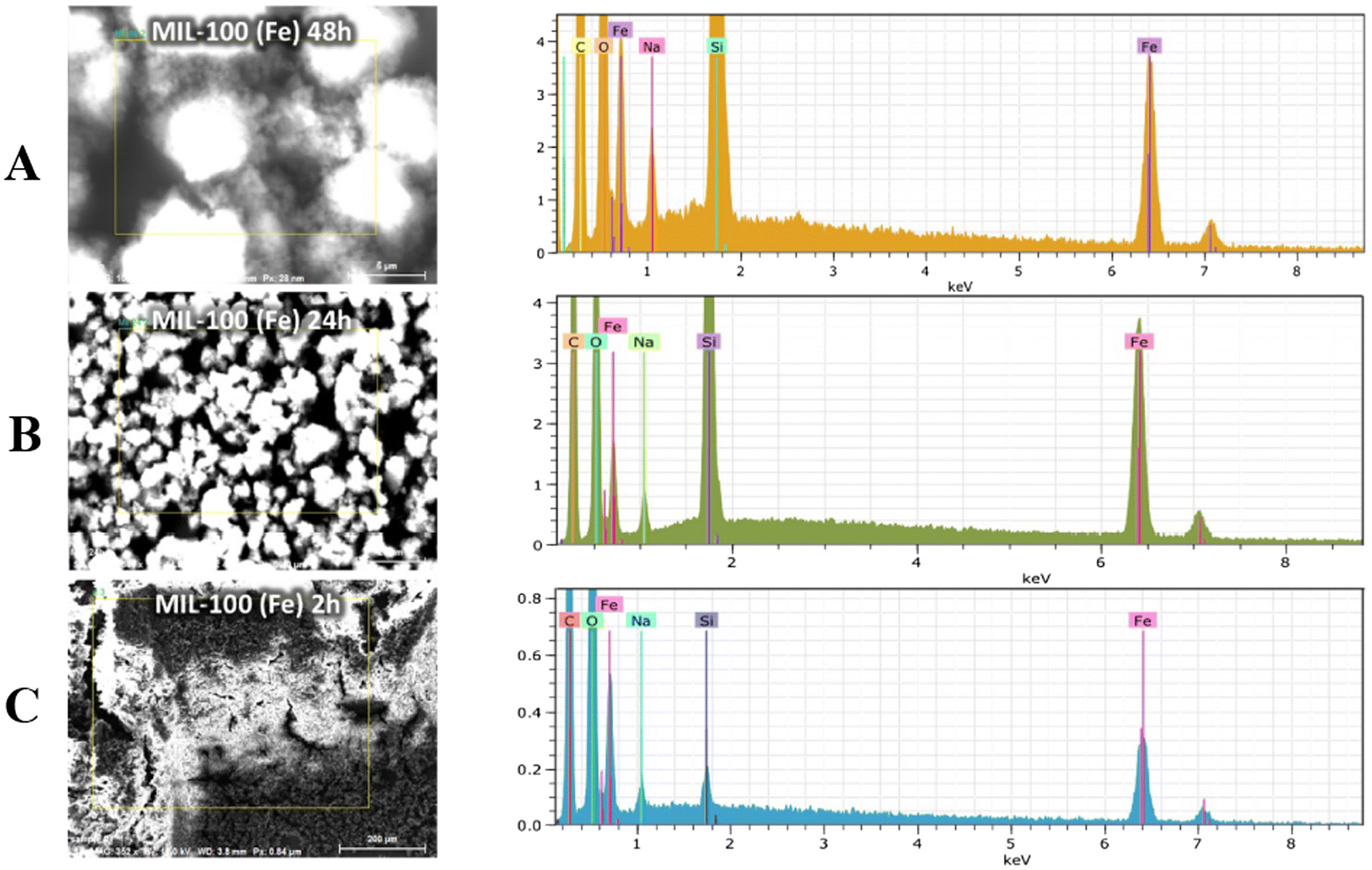 | ||
| Fig. 6 SEM-EDS spectra of MIL(100)-Fe after 48 h (A), 24 h (B) and 2 h (C) of synthesis. | ||
To better investigate the effect of different synthesis times, nitrogen adsorption isotherms of MIL(100)-Fe synthesized at 48 h, 24 h and 2 h of reaction were recorded and are shown in Fig. 7(A–C). All N2-sorption curves indicate a combination of type I and IV isotherms according to the IUPAC, typical of MIL-100(Fe), with a narrow hysteresis loop in the relative pressure (P/P0) range of 0.8–1.0. The surface area was calculated using the Brunauer–Emmett–Teller model (BET) and the obtained values are reported in Table 1, together with the pore volume values. The pore size distribution (Fig. 7C) is consistent with the existence of the two types of mesopores and the corresponding microporous windows (Fig. 7D and E).38,39 Interestingly, it is seen that the MIL-100(Fe) synthesized at 48 h, which showed the higher crystallinity, also has the highest surface area (1082 ± 18 m2 g−1) and the highest pore volume (0.696 cm3 g−1), confirming a correlation between the crystallinity and the BET results. These values are slightly lower than those found in the literature and similar to those reported by Ahmed et al.60 for MIL-100(Fe), obtained by dry gel conversion from metallic iron without any acid and salt (Table S1†).
 | ||
| Fig. 7 (A) BET nitrogen adsorption-desorption isotherms, (B) BHJ adsorption cumulative pore volumes, and (C) BJH adsorption dV/dD pore volumes of MIL-100(Fe) at 48 h (red curve), 24 h (black curve) and 2 h (pink curve) of synthesis. MIL(100)-Fe mesoporous cages: (D) medium cage (24 Å) and (E) large cage (29 Å) (ref. 38). | ||
| Synthesized MIL-100(Fe) samples | Synthesis time (h) | BET surface area (m2 g−1) | Pore volume (cm3 g−1) |
|---|---|---|---|
| Sample 1 | 2 h | 302 ± 10 | 0.349 |
| Sample 2 | 24 h | 956 ± 15 | 0.602 |
| Sample 3 | 48 h | 1082 ± 18 | 0.696 |
Electrochemical characterization of the MIL-100(Fe)/MWCNTs/SPE
The electrochemical behavior of the MWCNTs/SPE before and after the modification with MIL-100(Fe) was studied by CV experiments. Fig. 8 shows the cyclic voltammograms of the MWCNTs/SPE obtained before (black curve) and after modification with MIL-100(Fe) at different synthesis times. In all CVs, a pair of quasi-reversible redox peaks is evident, with slight increases in the peak-to-peak separations (ΔEp) observed in the modified electrodes. The electroactive area (Ae) and roughness factor (ρ) were subsequently calculated from the CV curves and are presented in Table 1. The Ae was determined by plotting the peak current against the square root of the scan rate (v1/2) and incorporating the obtained slope value into the following Randles–Sevcik equation:61| Ip = 2.686 × 10⁵n3/2AeD01/2C0v1/2 | (1) |
 | ||
| Fig. 8 CV curves of the MWCNTs/SPE (black curve), the MIL100(Fe) 2 h/MWCNTs/SPE (red curve), the MIL100(Fe) 24 h/MWCNTs/SPE (green curve) and the MIL100(Fe) 48 h/MWCNTs/SPE (blue curve) measured in 2.5 mM Zobell's solution. Scan rate: 25 mV s−1. | ||
It is clear that by prolonging the synthesis time to 48 h there is a large increase in the peak current (blue curve) compared to the 24 h (green curve) and 2 h (red curve) synthesis times. This large enhancement may be ascribed to the better redox conductivity of the 48 h MIL(100)-Fe film drop-cast on the electrode surface, thanks to the higher surface area and higher porosity of its microporous–mesoporous structure with a consequent increase in the electrode surface area.62Table 2 displays the heterogeneous electron transfer rate constants (k0, cm s−1) for the MWCNTs/SPE before and after modification with MIL-100(Fe), calculated using the method reported by Lavagnini et al., which is an integration of the Klingler–Kochi and Nicholson and Shain methods for irreversible and reversible systems, respectively.63 The 48 h MIL-100(Fe)/MWCNTs/SPE exhibited the highest k0 value, confirming that the higher crystallinity and higher porosity of the 48 h MOF facilitate a faster electron transfer kinetics. As shown, the optimum synthesis time was 48 h in terms of crystallinity, porosity and electrochemical performances and therefore the 48 h MIL-100(Fe) was chosen for further experiments. The term MIL-100(Fe) will refer to the 48 h MIL-100(Fe) in the following sections.
| Platform | A e/cm2 | ΔE/mV | ρ | k 0 10−3/cm s−1 |
|---|---|---|---|---|
| MWCNTs/SPE | 0.09 ± 0.001 | 109 | 0.824 | 0.7341 ± 0.001 |
| MIL-100(Fe) 2 h/MWCNTs/SPE | 0.12 ± 0.001 | 144 | 1.090 | 0.7431 ± 0.001 |
| MIL-100(Fe) 24 h/MWCNTs/SPE | 0.13 ± 0.001 | 119 | 1.181 | 0.7499 ± 0.001 |
| MIL-100(Fe) 48 h/MWCNTs/SPE | 0.21 ± 0.002 | 134 | 1.909 | 0.7821 ± 0.001 |
Electrochemical characterization of the VEGF immunosensor platform
The electrochemical behavior of the MWCNTs/SPE following each surface modification step conducted for the development of a VEGF immunosensor was investigated using differential pulse voltammetry (DPV) and electrochemical impedance spectroscopy (EIS).DPV characterization
Fig. 9A shows the DPV curves corresponding to each surface modification step of the VEGF immunosensor. Compared to the unmodified MWCNTs/SPE (black curve), a significant increase in the peak current is observed after modification with MIL-100(Fe) (blue curve), thanks to the superior conductive properties of the MOF. Then, a progressive decrease in the peak current is observed corresponding to the following steps: (i) anchoring of VEGF antibody (red curve); (ii) saturating with HSA (green curve); and (iii) formation of a VEGF Ab–Ag complex (orange curve). These results indicate that the electron transfer of the electrode is progressively hampered by the insulating nature of the antibody, HSA and antigen biomolecules, thus confirming the successful immobilization of these biomolecules on the electrode surface. | ||
| Fig. 9 (A) DPV curves of the MWCNTs/SPE (black curve), the MOF/MWCNTs/SPE (blue curve), the Ab/MOF/MWCNTs/SPE (red curve), the HSA/Ab/MOF/MWCNTs/SPE (green curve) and the Ag/HSA/Ab/MOF/MWCNTs/SPE (orange curve) measured in 2.5 mM Zobell's solution; VEGF antibody = 10 μg mL−1; [VEGF Ag] = 500 pg mL−1; (B) Nyquist plots of the MWCNTs/SPE (black curve), the MOF/MWCNTs/SPE (blue curve), the Ab/MOF/MWCNTs/SPE (red curve), the HSA/Ab/MOF/MWCNTs/SPE (green curve) and the Ag/HSA/Ab/MOF/MWCNTs/SPE (pink curve) measured in 2.5 mM Zobell's solution. Inset: simple Randles circuit. [VEGF Ag] = 500 pg mL−1. | ||
EIS characterization
Nyquist plots corresponding to each modification step of the immunosensor platform were recorded and fitted by a simple Randles circuit (Fig. 9B). Compared to the bare electrode (black curve), after the immobilization of MIL-100(Fe), it is possible to observe a slight decrease in the RCT value (259 Ω), indicating a higher electron transfer rate between the redox probe and the electrochemical double layer, probably due to the formation of electrostatic interactions between MIL-100(Fe) and the –COOH functional groups of MWCNTs. This results in a smaller semicircle (blue curve), demonstrating that the MOF effectively enhances the conductivity of the electrode/electrolyte interface, thanks to its superior electroconductive properties. A significant increase in the semicircle diameter (RCT) was observed following the immobilization of VEGF Ab (red curve), indicating a well-oriented affinity binding of the antibodies, leading to electron transfer hindrance. A further increase in the RCT value was observed after the immobilization of HSA protein (green curve), used as a blocking agent to prevent non-specific interactions, and VEGF antigen (orange curve). In all cases, the increase in the RCT value is due to the mass transfer limitation of [Fe(CN)63−/4−] to the electrode surface by the immobilized biomolecules. The acquired data were fitted using the Randles equivalent circuit [R(Q[RW])], incorporating components such as the resistance of the electrolyte solution (Rs), the charge transfer resistance (RCT), the constant phase element (Q), and the Warburg element (W) (Fig. 10, inset), and are presented in Table 3. In particular, the RCT value exhibited a 257%, 476%, and 644% enhancement after the immobilization of VEGF antibody, HSA protein, and VEGF antigen, respectively. This enhancement was calculated using the following equation: | (2) |
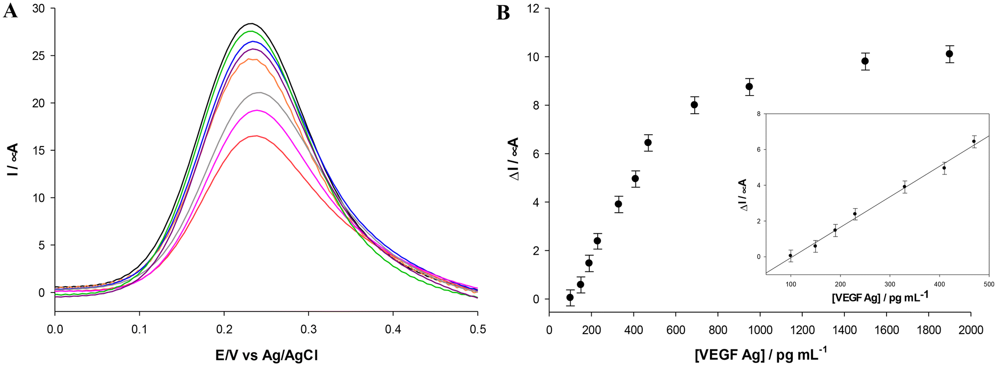 | ||
| Fig. 10 Panel A: DPV curves of the HSA/Ab/MOF/MWCNTs/SPE (black curve) modified with varying concentrations of VEGF Ag (from 150–1900 pg mL−1; from green to red curves) measured in 2.5 mM Zobell's solution. Panel B: calibration plots for different VEGF concentrations (from 150–1900 pg mL−1 in PBS pH 7.2). Inset: magnification of the linear range. Experimental conditions: 2.5 mM Zobell's solution; VEGF antibody = 10 mg mL−1. | ||
| MWCNTs/SPE | R s (Ω) | R CT (Ω) | W (μMho s1/2) | Q | |
|---|---|---|---|---|---|
| Y 0 (μMho) | N | ||||
| Bare | 141 | 589 | 1.16 | 64 | 0.655 |
| MIL-100(Fe) | 132 | 259 | 240 | 457 | 0.612 |
| Ab/MIL-100(Fe) | 136 | 926 | 407 | 249 | 0.492 |
| HSA/Ab/MIL-100(Fe) | 139 | 1494 | 521 | 203 | 0.524 |
| Ag/HSA/Ab/MIL-100(Fe) | 143 | 1927 | 393 | 114 | 0.699 |
Optimization of the VEGF electrochemical platform
Various parameters such the antibody concentration, its binding time and the antigen incubation time were optimized by DPV experiments in order to achieve the best electrochemical performances of the sensing platform. As shown in Fig. S1,† the current density reached a minimum value, confirming saturation of the electrode surface at an antibody concentration of 10 μg mL−1 and with a binding time of 4 h. As for VEGF antigen incubation, different time periods between 10 and 90 minutes have been tested and an incubation time of 60 minutes resulted in an optimum value showing a minimum current response.VEGF immunosensor
DPV experiments were performed for the development of the VEGF immunosensor. With increasing antigen concentration, a progressive reduction of the oxidation current signal (Fig. 10A) is observed, due to the non-conductive nature of the antigen. The calibration curve shown in Fig. 10B demonstrates a dynamic linear relationship between the current density and the VEGF concentration in the range of 100–480 pg mL−1, a detection limit (LOD) of 50 pg mL−1 calculated using the formula 3σ/S with σ being the standard deviation of the intercept and S the slope of the calibration plot, and a sensitivity of 0.017 mA mL pg−1. The corresponding linear regression equation was y = 0.017x − 1.758 with an R2 value of 0.994 (n = 3, RSD < 5%). Table 4 shows a brief overview of other VEGF voltammetric immunosensors reported in the literature. Based on the reported data, there is only another cobalt-MOF-based immunosensor for VEGF detection,64 but it shows 4 times higher LOD value compared to the Fe-MOF developed in our work. As for the dynamic linear range, the proposed immunosensor showed a more restricted linear range but it is within the physiological concentration of VEGF in human serum, considering a threshold limit among healthy individuals and cancer patients of about 210 pg mL−1.65,71 Moreover, MIL-100(Fe) has been synthesized using a heatless procedure, whereas the Co-based MOF has been synthesized using the classical hydrothermal method, which requires the use of a thermal autoclave. Most other works reported in Table 4 have been tested in buffer and not in human/animal serum and therefore the results are not directly comparable. Lastly, the very recent nanoporous Au-based immunosensor71 tested in human serum spiked with VEGF concentrations showed a remarkable LOD and linear response range, but it must be considered that its preparation requires a silver and gold deposition step on a fluorine-doped tin oxide substrate, followed by a thermal annealing process in a furnace at 550 °C and a dealloying process with HNO3 solution. The findings illustrate the superior characteristics of the proposed MIL-100(Fe) electrochemical platform in terms of sustainability, environmental friendliness, and costs, as it does not require high temperature, high pressure or toxic chemicals.| Platform | Transducer | Sample | LOD (pg mL−1) | Linear range (ng mL−1) | Ref. |
|---|---|---|---|---|---|
| Co-BTC/GO/MOFs | DPV | Animal serum | 199 | 10−5 to 100 | 64 |
| rGO/AuNPs | CV and SWV | Buffer | 0.006 | 2–2000 | 66 |
| rGO/AuNPs | SWV and EIS | Buffer | 0.007 | 0.020–0.120 | 67 |
| ERGO | SWV | Buffer | 0.1 | 10−4–100 | 68 |
| PEDOT/AuNPs | EIS | Buffer | 0.5 | 10−3–0.02 | 69 |
| Insulated disk-shaped carbon fiber microelectrode | LSV | Buffer | 38 | 10−3–0.1 | 70 |
| Au nano-porous/MAA/EDC-NHS/VHH/gelatin | CV and EIS | Spiked serum | 0.05 | 10−4–100 | 71 |
| MIL-100(Fe)/MWCNTs | DPV | Human serum | 50 | 0.1–0.48 | This work |
Selectivity, reproducibility and stability of the VEGF immunosensor
The selectivity of the proposed platform was assessed by comparing the DPV signals obtained in the presence of VEGF with those obtained in the presence of other proteins, such as bovine serum albumin (BSA), prostate-specific antigen (PSA), glucose (Glu), and cholesterol (Cho). The DPV signals were recorded after a 30 minute incubation period of each protein on the HSA/Ab/MIL-100(Fe)/MWCNTs/SPE platform. In particular, a concentration of 500 pg mL−1 was used for the VEGF protein, while a concentration of 5000 pg mL−1 was utilized for the four interferents tested. No significant signals were detected for all interferents, despite their use at ten times higher concentration (Fig. 11), confirming the high selectivity of the proposed immunosensor, thanks to the specificity of the properly oriented VEGF antibody recognition sites towards the VEGF target antigen. The reproducibility was evaluated by measuring 500 pg mL−1 of VEGF with ten immunosensors fabricated under identical conditions. The relative standard deviation (RSD) was calculated to be 7.4%, indicating a satisfactory reproducibility. The stability of the VEGF platform was also evaluated by DPV analysis. The electrode was kept at 4 °C for a period of 30 days, with regular monitoring every 5 days. During the first 10 days, the current remained quite stable and after day 10 the current started to gradually decline over time. However, the immunosensor maintained more than 85% of the current response after 1 month, indicating very good storage stability, as illustrated in Fig. S2.†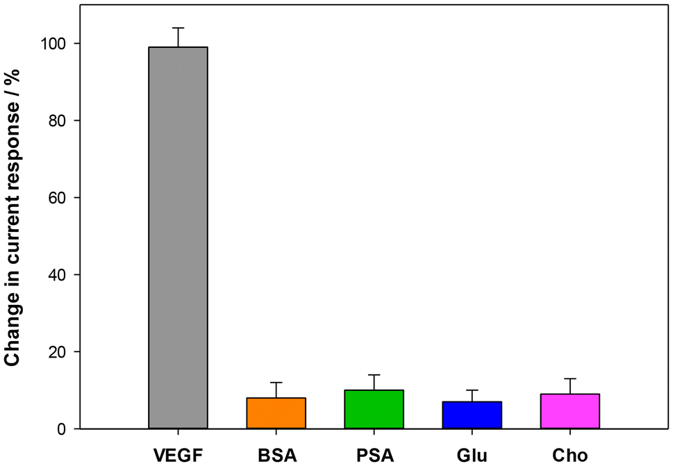 | ||
| Fig. 11 Histograms of selectivity assay for VEGF (500 pg mL−1) vs. different potential interferents (5000 pg mL−1) in 2.5 mM Zobell's solution. | ||
Application in real serum samples
The proposed immunosensor was tested in 5 human serum samples of cancer patients. Table 5 shows the correlation between the outcomes of the developed immunosensor and the conventional ELISA method. Notably, the results exhibit a good agreement between the two techniques, with RSD% values ranging between 14 and 24. These results suggest the efficacy of the proposed immunosensor in accurately quantifying VEGF levels in human serum samples.| Sample | ELISA/pg mL−1 | Immunosensor/pg mL−1 | RSD % |
|---|---|---|---|
| Patient 1 | 218 ± 2.15 | 278 ± 1.95 | 24 |
| Patient 2 | 477 ± 3.96 | 587 ± 4.58 | 18 |
| Patient 3 | 263 ± 5.34 | 301 ± 3.26 | 14 |
| Patient 4 | 387 ± 3.91 | 453 ± 2.88 | 17 |
| Patient 5 | 472 ± 2.52 | 598 ± 3.75 | 21 |
Materials and methods
Reagents
The anti-VEGF antibody (VEGF Ab) was purchased from Bio-Techne R&D Systems (Minneapolis, USA). The VEGF antigen (VEGF Ag) was purchased from Biorbyt (Cambridge, UK). Human serum albumin (HSA), potassium chloride (KCl, 99–100.5%), potassium ferricyanide(III) (K3[Fe(CN)6], 99.0%), potassium ferrocyanide(II) (K4[Fe(CN)6], 98.5–102.0%), sodium phosphate monobasic (NaH2PO4, ≥99%), sodium phosphate dibasic (Na2HPO4, ≥99%), iron(II) chloride tetrahydrate (FeCl2·4H2O) and trimesic acid (H3BTC) were purchased from Sigma-Aldrich (Bucks, Germany). Each solution was made in 0.1 M phosphate buffer and 0.1 M KCl and adjusted to a pH of 7.1 (PBS). During the investigations, high-purity deionized water sourced from Millipore (Molsheim, France) was used (resistance: 18.2 MΩ cm at 25 °C; TOC < 10 μg L−1). All chemicals utilized were of analytical grade and were used as received without undergoing any additional purification processes.Electrochemical measurements and apparatus
Electrochemical measurements were conducted in a 10 mL conventional three-electrode thermostated glass cell (model 6.1415.150, Metrohm, Herisau, Switzerland) employing a multi-walled carbon nanotube screen-printed electrode (MWCNTs-SPE, CNT110 Metrohm, Herisau, Switzerland) as the working electrode, an external Ag/AgCl/KClsat electrode (198 mV vs. NHE) as the reference electrode (cat. 6.0726.100, Metrohm, Herisau, Switzerland), and a glassy carbon rod as the counter electrode (cat. 6.1248.040, Metrohm, Herisau, Switzerland). The electrochemical measurements were performed using an Autolab potentiostat/galvanostat (Eco Chemie, The Netherlands).Electrochemical impedance spectroscopy (EIS) data were obtained in the frequency range of 0.1–103 Hz employing an AC signal with an amplitude of 10 mV and conducted under open-circuit potential (OCP) conditions.
Cyclic voltammetry (CV), differential pulse voltammetry (DPV), and electrochemical impedance spectroscopy (EIS) analyses were conducted utilizing a 15 mL solution comprising a mixture of 2.5 mM Fe(CN)63−/Fe(CN)64− and 0.1 M KCl dissolved in distilled water, serving as an electrochemical redox probe (referred to as Zobell's solution).
The modification of all the functionalization steps was monitored by DPV and EIS experiments. The quantitative analysis for the construction of the immunosensor calibration curve was performed by decreasing the peak current of DPV with increasing VEGF concentration.
In CV experiments, Zobell's solution was employed to ascertain the electroactive area (Ae) utilizing the Randles–Ševcik equation, the roughness factor (ρ = Ae/Ageom) and the heterogeneous electron transfer rate constant (k0).
Scanning electron microscopy (SEM) and energy-dispersive X-ray spectroscopy (EDX)
SEM and EDX analyses were conducted using a Zeiss Auriga high-resolution field emission scanning electron microscope (HR FESEM). Imaging was performed at an EHT voltage of 1.5/3 kV. For sample preparation, 5 μl of the sample was drop-cast on a silicon substrate and air dried.Transmission electron microscopy (TEM)
TEM analysis was conducted using a JEOL 1200 EX2 instrument (JEOL USA, Massachusetts, USA) operating at an acceleration voltage of 150 kV. The size of MOF-MIL 100(Fe) was measured using ImageJ software25 by analyzing a minimum of 10 TEM images. For TEM sample preparation, 10 μL of MOF-MIL 100(Fe) solution was drop-cast onto a carbon film on mesh copper substrate (C200Cu, EMR Resolutions, Sheffield, UK) and allowed to air-dry for 24 hours.Powder X-ray diffraction (PXRD)
PXRD patterns were obtained using a Malvern Panalytical X'Pert Pro diffractometer with Bragg-Brentano geometry utilizing Cu Kα radiation with a wavelength of 0.154184 nm. The instrument was equipped with an ultrafast X'Celerator RTMS detector. The resulting scans were analyzed employing X'Pert High Score Plus software.X-ray photoelectron spectroscopy (XPS)
XPS measurements were carried out using a modified Omicron NanoTechnology MXPS system equipped with a monochromatic Al Kα (hν = 1486.7 eV) X-ray source. The C 1s and Fe 2p photoionization regions were acquired using an analyzer pass energy of 20 eV and a take-off angle of 21° with respect to the sample surface normal.Raman spectroscopy
Raman spectra were recorded at room temperature using an inVia Renishaw micro-Raman spectrometer with a backscattering geometry. The spectrometer was outfitted with an air-cooled CCD detector and super-notch filters. An Ar+ ion laser with a wavelength of 514 nm coupled to a Leica DLML microscope equipped with a 20× objective was employed. Spectral resolution was set at 2 cm−1 and spectra were calibrated using the 520.5 cm−1 line of a silicon wafer. Multiple spots on the sample surface were probed to record Raman spectra.Thermogravimetry/differential thermal analysis (TG/DTA)
TG/DTA profiles were obtained using a Netzsch STA 409 PC Luxx simultaneous thermal analyzer.BET analysis
Surface area and pore analysis were obtained by N2 adsorption/desorption measurements, at liquid nitrogen temperature (−196 °C), using Micromeritics 3Flex 3500 analyzer, by using the Brunauer-Emmett-Teller (BET) multipoint method.72 The samples were pre-treated under vacuum at 140 °C for 4 hours. Pore size distribution was determined using the Barret–Joyner–Halenda (BJH) method.73 The analysis of micropores was performed by the t-test;74 the total pore volume was determined by the rule of Gurvitsch.75Synthesis of MIL-100(Fe)
MOF MIL-100(Fe) was synthesized following a procedure reported in the literature.44 Two distinct solutions were prepared as follows: solution 1 was prepared by dissolving 167.1 mg of H3BTC in 3 mL of an aqueous solution containing 1 M NaOH, while solution 2 was prepared by dissolving 226.6 mg of FeCl2·4H2O in 10.72 mL of distilled water. Subsequently, solution 1 was cautiously added drop by drop into solution 2 with continuous stirring. The stirring process was performed at room temperature for 24 hours or 48 hours. Following this, the resultant solution underwent three wash cycles with distilled water (10 mL each) and an additional wash with absolute ethanol (10 mL) via centrifugation at 6000 rpm. The resulting solid was then collected, resuspended in absolute ethanol, and designated as MOF-MIL 100(Fe). An analogue reaction was also performed with a stirring time of 2 hours. A reddish crystalline precipitate forms but the crystalline phase does not match the one of MIL-100(Fe).Immunosensor fabrication steps
The immunosensor was prepared using the following steps: (1) 10 μL of MOF-MIL 100(Fe) was deposited onto the working area of the MWCNTs-SPE via drop-casting and left to dry under vacuum for 2 hours; (2) the modified electrode was incubated in VEGF Ab solution (10 μg mL−1, prepared in 0.1 M PBS at pH 7.1) for 4 hours; (3) 10 μL of HSA solution (0.25% w/v) was dropped on the electrode surface (15 minutes) as a blocking agent to prevent non-specific interactions; and (4) 10 μL of varying concentrations of VEGF Ag (ranging from 100 to 1900 pg mL−1) were deposited onto the surface of the immunosensor and allowed to dry at room temperature for 30 minutes. The electrode surface was rinsed with buffer solution at the end of each fabrication step. The comprehensive modification stages of the working electrode for the construction of the VEGF immunosensor are presented in Fig. 12. | ||
| Fig. 12 Preparation of the modified MWCNTs/SPE by (1) MOF-MIL 100(Fe) deposition, (2) VEGF Ab immobilization, (3) HSA surface blocking and (4) VEGF Ag binding. Inset: procedures for the synthesis of MIL 100(Fe) 2 h, MIL 100(Fe) 24 h and MIL 100(Fe) 48 h. | ||
Preparation of the human serum sample
Sera were collected from metastatic renal cell carcinoma patients (from Policlinico Umberto I Hospital-Sapienza University of Rome) using BD Vacutainer Plus plastic serum tubes (Becton Dickinson) after centrifugation at 1800 rpm for 10 minutes. Sera were then cryopreserved until use.Before all measurements, human serum samples were appropriately diluted with 0.1 M PBS, pH 7.1 (0.1 M KCl) at a dilution ratio of 1:100.
ELISA test
VEGF was evaluated in the serum of metastatic renal cell carcinoma patients before the beginning of therapy using the Human VEGF Quantikine ELISA Kit, (R&D System, cat. no. DVE00) according to the manufacturer’ instructions. The concentration of VEGF was evaluated using a Multiskan FC (Thermo Fisher Scientific) at 450 nm of absorbance.Conclusions
In summary, a novel ecofriendly immunosensor based on the immobilization of VEGF antibody on a MWCNTs/SPE modified with MIL-100(Fe) has been constructed for the detection of the VEGF tumor biomarker.MIL-100(Fe) was successfully synthesized using a “green” and sustainable method, which does not require any acid, harsh chemicals or heating. The morphology and structure and, hence, the electrochemical properties of the so-synthesized MOF are directly correlated with its synthesis parameters. The synthesis reaction time has been varied in order to investigate its effect on the structure–electrochemical property relationships. To this end, the synthesis time has been varied in the range of 2–48 h. Several physical measurements were conducted and the results obtained showed that the MIL-100(Fe) synthesized at 48 h showed the highest degree of crystallinity and the highest surface area and pore volume. The electrochemical experiments clearly showed a direct correlation between crystallinity, porosity and better electroconductive properties. The MIL-100(Fe) 48 h/MWCNTs/SPE-based immunosensor showed a low detection limit of 50 pg mL−1 and a linear range in the clinically relevant range of VEGF in human serum, useful to help diagnosis, prognosis, and monitoring of several cancers associated with the expression of VEGF.
Since VEGF is recognized as an important cancer biomarker that plays a crucial role in tumor growth, monitoring VEGF levels could allow the assessment of tumor status in many cases.
Hence, the proposed device is a beneficial immunosensor, which combines, unlike other VEGF immunosensors recently reported in the literature, a sustainable, eco-friendly, easy and low-cost fabrication with high sensitivity, good reproducibility, high selectivity, and an ideal dynamic range to detect VEGF in the serum of cancer patients. Moreover, these characteristics highlight the appropriateness of the proposed biosensor for extensive applications, positioning it as an optimal candidate in other research contexts and disease settings, such as infectious diseases.
Author contributions
I. G. Z. and R. A.: conceptualization, data curation, investigation, funding acquisition, and writing – original draft. V. G.: investigation and data curation. T. G.: investigation. C. T.: investigation. A. L.: investigation. A. R., A. I., and M. N.: validation; R. A.: project administration and supervision. All authors: writing – review & editing.Ethics declarations
The study was conducted in accordance with the Declaration of Helsinki and with good clinical practice guidelines. All patients signed informed consent. The Institutional Ethics Committee of the involved institution (Policlinico Umberto I Hospital-Sapienza University Ethics Committee) agreed to the final version of the protocol (RIF.CE: 4181). All experiments were performed in accordance with relevant guidelines and regulations.Data availability
The data supporting this article have been included as part of the ESI.†Conflicts of interest
There are no conflicts to declare.Acknowledgements
This work has been supported by Project "Proof of Concept (PoC) PNRR 2023 - NextGenerationEU" Ministero delle Imprese e del Made in Italy and Sapienza University (CUP C88H23000760001). The authors thank Prof. Andrea Marrani from Sapienza University for the support on the XPS and Raman analyses. Prof. Ida Pettiti is acknowledged for the gas absorption measurements and BET analysis. Also, the assistance of Dr Fabio Scirocchi from Sapienza University on the ELISA measurements is gratefully acknowledged. Moreover, M. C. di G. acknowledges the support from the program “Rita Levi Montalcini for young researchers” of the Italian Ministry of University and Research.References
- M. Ding, R. W. Flaig, H.-L. Jiang and O. M. Yaghi, Chem. Soc. Rev., 2019, 48, 2783–2828 RSC.
- S. Yuan, L. Feng, K. Wang, J. Pang, M. Bosch, C. Lollar, Y. Sun, J. Qin, X. Yang, P. Zhang, Q. Wang, L. Zou, Y. Zhang, L. Zhang, Y. Fang, J. Li and H. Zhou, Adv. Mater., 2018, 30, 1704303 Search PubMed.
- L. Chen, R. Luque and Y. Li, Chem. Soc. Rev., 2017, 46, 4614–4630 RSC.
- M. Safaei, M. M. Foroughi, N. Ebrahimpoor, S. Jahani, A. Omidi and M. Khatami, TrAC, Trends Anal. Chem., 2019, 118, 401–425 Search PubMed.
- B. Le Ouay, C. Watanabe, S. Mochizuki, M. Takayanagi, M. Nagaoka, T. Kitao and T. Uemura, Nat. Commun., 2018, 9, 3635 CrossRef PubMed.
- G. Gao, Y. Wang, H. Zhu, Y. Chen, R. Yang, C. Jiang, H. Ma and Y. Lan, Adv. Sci., 2020, 7, 2002190 CrossRef CAS PubMed.
- J. Lyu, X. Zhang, K. Otake, X. Wang, P. Li, Z. Li, Z. Chen, Y. Zhang, M. C. Wasson, Y. Yang, P. Bai, X. Guo, T. Islamoglu and O. K. Farha, Chem. Sci., 2019, 10, 1186–1192 RSC.
- X. Xie, X. Huang, W. Lin, Y. Chen, X. Lang, Y. Wang, L. Gao, H. Zhu and J. Chen, ACS Omega, 2020, 5, 13595–13600 CrossRef CAS PubMed.
- Q. He, P. Tu and J. L. Sessler, Chem, 2018, 4, 46–93 CAS.
- C. Doonan, R. Riccò, K. Liang, D. Bradshaw and P. Falcaro, Acc. Chem. Res., 2017, 50, 1423–1432 CrossRef CAS PubMed.
- J. D. Evans, C. J. Sumby and C. J. Doonan, Chem. Soc. Rev., 2014, 43, 5933–5951 RSC.
- E. Binaeian, E.-S. M. El-Sayed, M. Khanpour Matikolaei and D. Yuan, Coord. Chem. Rev., 2021, 430, 213738 CrossRef CAS.
- S. Ma, C. Wei, Y. Bao, Y. Liu, H. Jiang, W. Tong, D. Chen and X. Huang, Microchim. Acta, 2024, 191, 107 CrossRef CAS PubMed.
- R. E. Morris and P. S. Wheatley, Angew. Chem., Int. Ed., 2008, 47, 4966–4981 Search PubMed.
- J. Lee, O. K. Farha, J. Roberts, K. A. Scheidt, S. T. Nguyen and J. T. Hupp, Chem. Soc. Rev., 2009, 38, 1450 Search PubMed.
- S. Subudhi, S. P. Tripathy and K. Parida, Catal. Sci. Technol., 2021, 11, 392–415 RSC.
- H. Wang, B. Chen and D. Liu, Adv. Mater., 2021, 33, 2008023 CrossRef CAS PubMed.
- Q. Zhuang, R. Gao, M. Shi, X. Lin, A. Xie and W. Dong, ACS Appl. Nano Mater., 2021, 4, 3869–3876 CrossRef CAS.
- M. Zhong, L. Kong, K. Zhao, Y. Zhang, N. Li and X. Bu, Adv. Sci., 2021, 8, 2001980 CrossRef CAS PubMed.
- C. Hou and Q. Xu, Adv. Energy Mater., 2019, 9, 1801307 CrossRef.
- Z. Liang, C. Qu, W. Guo, R. Zou and Q. Xu, Adv. Mater., 2018, 30, 1702891 CrossRef PubMed.
- J. Yang and Y. Yang, Small, 2020, 16, 1906846 CrossRef CAS PubMed.
- X. Peng, L. Xu, M. Zeng and H. Dang, Int. J. Nanomed., 2023, 18, 4907–4931 CrossRef CAS PubMed.
- J.-H. Li, Y.-S. Wang, Y.-C. Chen and C.-W. Kung, Appl. Sci., 2019, 9, 2427 CrossRef CAS.
- A. Morozan and F. Jaouen, Energy Environ. Sci., 2012, 5, 9269 RSC.
- L. E. Kreno, K. Leong, O. K. Farha, M. Allendorf, R. P. Van Duyne and J. T. Hupp, Chem. Rev., 2012, 112, 1105–1125 CrossRef CAS PubMed.
- S.-N. Zhao, G. Wang, D. Poelman and P. Voort, Materials, 2018, 11, 572 CrossRef PubMed.
- I. Stassen, N. Burtch, A. Talin, P. Falcaro, M. Allendorf and R. Ameloot, Chem. Soc. Rev., 2017, 46, 3185–3241 RSC.
- L. Liu, Y. Zhou, S. Liu and M. Xu, ChemElectroChem, 2018, 5, 6–19 CrossRef CAS.
- G. Ashraf, T. Ahmad, M. Z. Ahmed, A. Murtaza and Y. Rasmi, Curr. Top. Med. Chem., 2022, 22, 2222–2240 CrossRef CAS PubMed.
- S. Carrasco, Biosensors, 2018, 8, 92 CrossRef CAS PubMed.
- B. Mohan, S. Kumar, H. Xi, S. Ma, Z. Tao, T. Xing, H. You, Y. Zhang and P. Ren, Biosens. Bioelectron., 2022, 197, 113738 CrossRef CAS PubMed.
- M. Daniel, G. Mathew, M. Anpo and B. Neppolian, Coord. Chem. Rev., 2022, 468, 214627 Search PubMed.
- Y. Song, Y. Shen, C. Gong, J. Chen, M. Xu, L. Wang and L. Wang, ChemElectroChem, 2017, 4, 1457–1462 CrossRef CAS.
- J. J. Delgado-Marín, J. Narciso and E. V. Ramos-Fernández, Materials, 2022, 15, 6499 Search PubMed.
- Q. Xia, H. Wang, B. Huang, X. Yuan, J. Zhang, J. Zhang, L. Jiang, T. Xiong and G. Zeng, Small, 2019, 15, 1803088 Search PubMed.
- Y. Fang, Z. Yang, H. Li and X. Liu, Environ. Sci. Pollut. Res., 2020, 27, 4703–4724 CrossRef CAS PubMed.
- P. Horcajada, S. Surblé, C. Serre, D.-Y. Hong, Y.-K. Seo, J.-S. Chang, J.-M. Grenèche, I. Margiolaki and G. Férey, Chem. Commun., 2007, 2820–2822 RSC.
- A. García Márquez, A. Demessence, A. E. Platero-Prats, D. Heurtaux, P. Horcajada, C. Serre, J. Chang, G. Férey, V. A. de la Peña-O'Shea, C. Boissière, D. Grosso and C. Sanchez, Eur. J. Inorg. Chem., 2012, 2012, 5165–5174 CrossRef.
- F. Jeremias, A. Khutia, S. K. Henninger and C. Janiak, J. Mater. Chem., 2012, 22, 10148–10151 RSC.
- F. Zhang, J. Shi, Y. Jin, Y. Fu, Y. Zhong and W. Zhu, Chem. Eng. J., 2015, 259, 183–190 CrossRef CAS.
- I. Bezverkhyy, G. Weber and J.-P. Bellat, Microporous Mesoporous Mater., 2016, 219, 117–124 CrossRef CAS.
- F. Zhang, Y. Jin, J. Shi, Y. Zhong, W. Zhu and M. S. El-Shall, Chem. Eng. J., 2015, 269, 236–244 CrossRef CAS.
- K. Guesh, C. A. D. Caiuby, Á. Mayoral, M. Díaz-García, I. Díaz and M. Sanchez-Sanchez, Cryst. Growth Des., 2017, 17, 1806–1813 CrossRef CAS.
- R. Zhu, M. Cai, T. Fu, D. Yin, H. Peng, S. Liao, Y. Du, J. Kong, J. Ni and X. Yin, Pharmaceutics, 2023, 15, 1599 CrossRef CAS PubMed.
- H. L. Goel and A. M. Mercurio, Nat. Rev. Cancer, 2013, 13, 871–882 CrossRef CAS PubMed.
- X. Guo, H. Yi, T. C. Li, Y. Wang, H. Wang and X. Chen, Biomolecules, 2021, 11, 253 CrossRef CAS PubMed.
- D. Pan, X. Gong, X. Wang and M. Li, Front. Pharmacol., 2021, 11, 594050 CrossRef PubMed.
- D. Klein, Front. Oncol., 2018, 8, 367 CrossRef PubMed.
- T. C. Elebiyo, D. Rotimi, I. O. Evbuomwan, R. F. Maimako, M. Iyobhebhe, O. A. Ojo, O. M. Oluba and O. S. Adeyemi, Cancer Treat. Res. Commun., 2022, 32, 100620 CrossRef PubMed.
- C. Zhang, L. Wang, C. Xiong, R. Zhao, H. Liang and X. Luo, J. Orthop. Surg. Res., 2021, 16, 738 CrossRef PubMed.
- O. G. Trifanescu, L. N. Gales, B. C. Tanase, S. A. Marinescu, R. A. Trifanescu, I. M. Gruia, M. A. Paun, L. Rebegea, R. Mitrica, L. Serbanescu and R. M. Anghel, Diagnostics, 2023, 13, 166 CrossRef CAS PubMed.
- P. Schlüter, O. Weller, I. Kanaan, L. Nel, B. Heusgen, P. Höing, S. Haßkamp, M. Zander, N. Mandapathil, J. Dominas, B. Arnolds, A. Stuck, S. Lang, A. Bankfalvi and S. Brandau, BMC Cancer, 2018, 18, 272 CrossRef PubMed.
- J. M. Kim and D. S. Chen, Ann. Oncol., 2016, 27, 1492–1504 CrossRef CAS PubMed.
- M. Nuti, Cancer Treat. Rev., 2018, 70, 41–46 CrossRef CAS PubMed.
- C. R. Quijia, C. Lima, C. Silva, R. C. Alves, R. Frem and M. Chorilli, J. Drug Delivery Sci. Technol., 2021, 61, 102217 CrossRef CAS.
- P. Horcajada, R. Gref, T. Baati, P. K. Allan, G. Maurin, P. Couvreur, G. Férey, R. E. Morris and C. Serre, Chem. Rev., 2012, 112, 1232–1268 CrossRef CAS PubMed.
- X. Li, L. Lachmanski, S. Safi, S. Sene, C. Serre, J. M. Grenèche, J. Zhang and R. Gref, Sci. Rep., 2017, 7, 13142 CrossRef CAS PubMed.
- M.-L. Chen, S.-Y. Zhou, Z. Xu, L. Ding and Y.-H. Cheng, Molecules, 2019, 24, 3718 CrossRef CAS PubMed.
- I. Ahmed, J. Jeon, N. A. Khan and S. H. Jhung, Cryst. Growth Des., 2012, 12, 5878–5881 CrossRef CAS.
- K. Oldham, J. Electroanal. Chem., 1979, 105, 373–375 CrossRef CAS.
- P. Wang, H. Zhao, H. Sun, H. Yu, S. Chen and X. Quan, RSC Adv., 2014, 4, 48912–48919 RSC.
- I. Lavagnini, R. Antiochia and F. Magno, Electroanalysis, 2004, 16, 505–506 CrossRef CAS.
- S. Singh, A. Numan, Y. Zhan, V. Singh, A. Alam, T. Van Hung and N. D. Nam, RSC Adv., 2020, 10, 27288–27296 RSC.
- S. Zhao, W. Yang and R. Y. Lai, Biosens. Bioelectron., 2011, 26, 2442–2447 CrossRef CAS PubMed.
- M. Pourmadadi, J. S. Shayeh, S. Arjmand, M. Omidi and F. Fatemi, Microchem. J., 2020, 159, 105476 CrossRef CAS.
- F. Taati Yengejeh, J. Shabani Shayeh, M. Rahmandoust, F. Fatemi and S. Arjmand, J. Biomed. Mater. Res., Part B, 2021, 109, 1505–1511 CrossRef CAS PubMed.
- R. Elshafey, P. Brisebois, H. Abdulkarim, R. Izquierdo, A. C. Tavares and M. Siaj, Electroanalysis, 2020, 32, 2205–2212 CrossRef.
- M. Kim, R. Iezzi, B. S. Shim and D. C. Martin, Front. Chem., 2019, 7, 234 CrossRef CAS PubMed.
- S. Prabhulkar, S. Alwarappan, G. Liu and C.-Z. Li, Biosens. Bioelectron., 2009, 24, 3524–3530 CrossRef CAS PubMed.
- S. Yarjoo, H. Siampour, M. Khalilipour, R. H. Sajedi, H. Bagheri and A. Moshaii, Sci. Rep., 2024, 14, 10450 CrossRef CAS PubMed.
- S. Brunauer, P. H. Emmett and E. Teller, J. Am. Chem. Soc., 1938, 60, 309–319 Search PubMed.
- E. P. Barrett, L. G. Joyner and P. P. Halenda, J. Am. Chem. Soc., 1951, 73, 373–380 CrossRef CAS.
- B. Lippens, J. Catal., 1965, 4, 319–323 Search PubMed.
- L. Gurvitsch, J. Soc. Phys.-Chim. Russe, 1915, 47, 805–827 Search PubMed.
Footnote |
| † Electronic supplementary information (ESI) available. See DOI: https://doi.org/10.1039/d5nr00471c |
| This journal is © The Royal Society of Chemistry 2025 |