
 Open Access Article
 This Open Access Article is licensed under a
 Creative Commons Attribution 3.0 Unported Licence
Plasmon-enhanced oxygen reduction reaction using silver nanoparticle-decorated N-doped carbon nanotubes†
Tereza
Jílková
 a,
Elena
Miliutina
a,
Andrii
Trelin
a,
Zdeňka
Kolská
b,
Václav
Švorčík
a,
Oleksiy
Lyutakov
a and
Roman
Elashnikov
*a
a,
Elena
Miliutina
a,
Andrii
Trelin
a,
Zdeňka
Kolská
b,
Václav
Švorčík
a,
Oleksiy
Lyutakov
a and
Roman
Elashnikov
*a
aDepartment of Solid State Engineering, University of Chemistry and Technology Prague, Technická 5, 166 28, Prague 6, Czech Republic. E-mail: roman.elashnikov@vscht.cz
bFaculty of Science, J. E. Purkyně University in Ústí nad Labem, Pasteurova 15, 400 01 Ústí nad Labem, Czech Republic
First published on 13th June 2025
Abstract
The oxygen reduction reaction (ORR) generally limits the efficacy of hydrogen fuel cells, due to its sluggish kinetics. Here, we present an effective plasmon-enhanced catalyst for the ORR, based on silver nanoparticle-decorated carbonized polypyrrole nanotubes (Ag-cPNTs). Silver nanoparticles (AgNPs) were incorporated onto the surface of carbonized polypyrrole nanotubes (cPNTs) using a straightforward and reproducible method without the need for wet synthesis. The cPNTs serve as redox-active supports with a high surface area, while AgNPs efficiently absorb and convert light energy into plasmonic excitation, facilitating oxygen activation. The successful introduction of AgNPs and their uniform morphology and size distribution were observed by scanning electron microscopy (SEM) and transmission electron microscopy (TEM). The analysis of the chemical composition, performed by X-ray diffraction (XRD) and X-ray photoelectron spectroscopy (XPS), confirmed the formation of AgNPs. Having been thoroughly characterized, the performance of the Ag-cPNTs was tested in the ORR under both illumination and dark conditions. LED illumination (455 nm central wavelength) of the prepared plasmon-active catalyst results in an increase of current density and LSV curve shift of potential to more positive values. Overall, a high surface area, porous interconnected structure, and photo-enhanced catalytic activity demonstrated high potential of the prepared composite as a novel catalyst for fuel cell applications.
1. Introduction
Low-temperature polymer electrolyte membrane fuel cells (PEMFCs), which use hydrogen and oxygen as fuels, are considered attractive options to internal combustion engines.1–4 The use of such PEMFCs reduces atmospheric emission of exhaust gases or particles that contribute to the formation of smog and are harmful to human health.5 The main obstacle to the widespread use of this technology is its high cost.6 One of the limiting reactions in such fuel cells is the electrochemical reduction of oxygen.7Due to the low oxygen reduction reaction (ORR) rate, the use of catalysts with high Pt content is required to achieve high power density.8 However, the high price of Pt, susceptibility to poisoning and poor operational stability hinder widespread commercialisation and use of PEMFCs. Thus, the development of sustainable, reproducible, and scalable alternative catalysts for the ORR is highly desired.9–13
A variety of metal- and carbon-based materials are actively being investigated as potential ORR catalysts to replace Pt.9,14–16 The efforts of researchers are aimed at either reducing the amount of Pt or its complete replacement.17 Among various alternatives, silver has shown promising performance in catalyzing the ORR, with the current research focusing on silver nanoparticle-based catalysts.18 Its low cost, currently about 30 times cheaper than Pt, and its superior stability in alkaline environments make it an attractive option as an ORR catalyst. Nevertheless, a significant limitation to the use of silver is its approximately 10 times lower catalytic activity compared to platinum, along with high overpotential values.18
To improve the ORR catalytic properties of silver nanoparticles (AgNPs), the influence of the nanoparticle shape and size on their effectiveness was investigated.19–22 Furthermore, effects of pH and electrolytes on AgNP ORR catalytic activity were studied.23,24 To achieve improved properties, silver-based alloys or halides have also been investigated.18,25 On the other hand, silver nanostructures can support the excitation of surface plasmon resonance with the related appearance of energy enriched, highly redox active charge carriers. However, fewer studies have focused on enhancing the ORR through the use of surface plasmon resonance. The intrinsic metal charge carriers or charge carriers in the closed catalytically active material are excited by plasmon decay, effectively activate absorbed oxygen molecules and improve the ORR efficiency.26,27 A similar concept has also been demonstrated for alternative energy-related applications, such as water splitting and nitrogen reduction, by utilizing plasmon-induced enhancement of material redox processes.28–34
Plasmon resonance can be adjusted by controlling the size, shape and distribution of the particles. However, most of these approaches required separate synthesis of AgNPs, using stabilizers, which remain on the AgNP surface and can worse catalytic activity. In particular, the presence of the stabilizer layer can prevent hot electron transfer as well as decrease the impact of the plasmonic field on the spatially separated redox active material. In addition, there is a need to solve the problem of nanoparticle immobilization on the support surface to avoid their aggregation and loss of catalytic activity.35 To the best of our knowledge, the direct preparation of plasmon-enhanced ORR catalysts, nitrogen-doped carbon nanotubes with a uniform distribution of AgNPs, without the need for wet synthesis has not been reported.
Here, we present plasmon-enhanced AgNP-decorated N-doped carbon nanotubes (Ag-cPNTs) as catalysts for the ORR. Ag-cPNTs were prepared using two-step synthesis: oxidation polymerization of polypyrrole nanotubes with addition of AgNO3 and subsequent carbonization under nitrogen flow. The synthesized N-doped carbon nanotubes served as catalysts and support which prevent agglomeration and aggregation of AgNPs. The prepared catalyst demonstrated the plasmon-enhanced ORR upon light illumination with low power LED sources. In this regard, the catalytic activity was provided by both the used materials (AgNPs and cPNTs), while plasmon triggering allows increasing the energy of charge carriers in both the materials (directly in AgNPs through plasmon decay and indirectly in nearby cPNTs due to the high local plasmon-induced electric field).
2. Results and discussion
The synthesis of Ag-cPNTs involved three steps that are presented in Scheme 1. First, polypyrrole nanotubes (PPyNTs) were synthesized by oxidative polymerization in the presence of methyl orange (MO). After PPyNT formation, as indicated by the characteristic blackening of the solution, a certain amount of silver nitrate was added, which resulted in precipitation of silver chloride nanoparticles. The formation of AgCl nanoparticles incorporated into the PPyNTs at this step was confirmed using SEM and SEM-EDX (Fig. S1, ESI†). The figure illustrates the distribution of Ag and Cl elements, as well as the distribution of N and C related to the polypyrrole. Next, dry PPyNTs containing AgCl were carbonized under nitrogen flow at 900 °C to obtain nitrogen-doped carbon nanotubes with silver nanoparticles on their surface (AgNPs) (see the Experimental section). The advantage of this method is the direct production of uniformly distributed silver nanoparticles on the surface of nanotubes without the need for additional wet syntheses or the use of stabilizers. Stabilizers (presented in the common cases) may have a negative effect on plasmon triggering of the redox activity of closed AgNP material. The use of stabilizers and reducing agents can lead, for instance, to surface blocking of silver, shifting the onset and half-wave potentials. According to the literature, uncoated particles enable a remarkably higher oxygen reduction current density and a more efficient pathway of the ORR.36,37 In addition, hot electrons excited due to Landau damping in AgNPs can scatter in the stabilizer layer without injection in the cPNTs. Finally, stabilizers spatially separate the AgNP and cPNT layer, decreasing the local value of plasmonic EF that affected the redox active material. | ||
| Scheme 1 Illustration of plasmon-active Ag-cPNT composite preparation: (i) synthesis of polypyrrole nanotubes (PPyNTs) and (ii) addition of AgNO3 with subsequent carbonization under nitrogen flow. | ||
The successful formation of Ag-cPNTs was confirmed by transmission and scanning electron microscopies (Fig. 1a and b), indicating the formation of cPNTs and uniformly distributed AgNPs over the cPNT surface. The average diameter of nanotubes was 102 ± 14 nm. Image analysis of TEM scans showed that on the surface of cPNTs, spherical AgNPs were formed with an average diameter of 57 ± 12 nm. The cPNTs serve as conductive support, which prevents AgNP aggregation. Even the formation of such plasmonic dimers (or multimers) is responsible for the creation/excitation of the so-called local plasmonic hot spots, where the maximal plasmonic enhancement of the plasmonic electric field (i.e. very efficient pumping light energy into the energy of charge hot carriers) is reached. Optimal AgNP coverage was achieved at an AgNO3 to pyrrole monomer molar ratio of 2![[thin space (1/6-em)]](https://www.rsc.org/images/entities/char_2009.gif) :1. The lower molar ratio of 1:1 led to high inhomogeneity of the AgNP distribution and coverage of the cPNT surface (Fig. S2, ESI†). In turn, carbonization of the PPyNTs obtained by adding an excessive amount of AgNO3 (molar ratio of 4:1) led to drastic changes in the morphology of the nanotubes, formation of porous spherical carbon nanofeatures and uneven distribution of AgNPs. To confirm that these carbon nanofeatures are formed only in the presence of AgNO3, carbonization of pristine PPyNTs was performed (Fig. S3, ESI†). No such nanofeatures were observed. In addition, SAED and HRTEM analyses indicated that in the amorphous state of cPNT nanotubes, no particles or iron oxides were observed (Fig. S3, ESI†).
:1. The lower molar ratio of 1:1 led to high inhomogeneity of the AgNP distribution and coverage of the cPNT surface (Fig. S2, ESI†). In turn, carbonization of the PPyNTs obtained by adding an excessive amount of AgNO3 (molar ratio of 4:1) led to drastic changes in the morphology of the nanotubes, formation of porous spherical carbon nanofeatures and uneven distribution of AgNPs. To confirm that these carbon nanofeatures are formed only in the presence of AgNO3, carbonization of pristine PPyNTs was performed (Fig. S3, ESI†). No such nanofeatures were observed. In addition, SAED and HRTEM analyses indicated that in the amorphous state of cPNT nanotubes, no particles or iron oxides were observed (Fig. S3, ESI†).
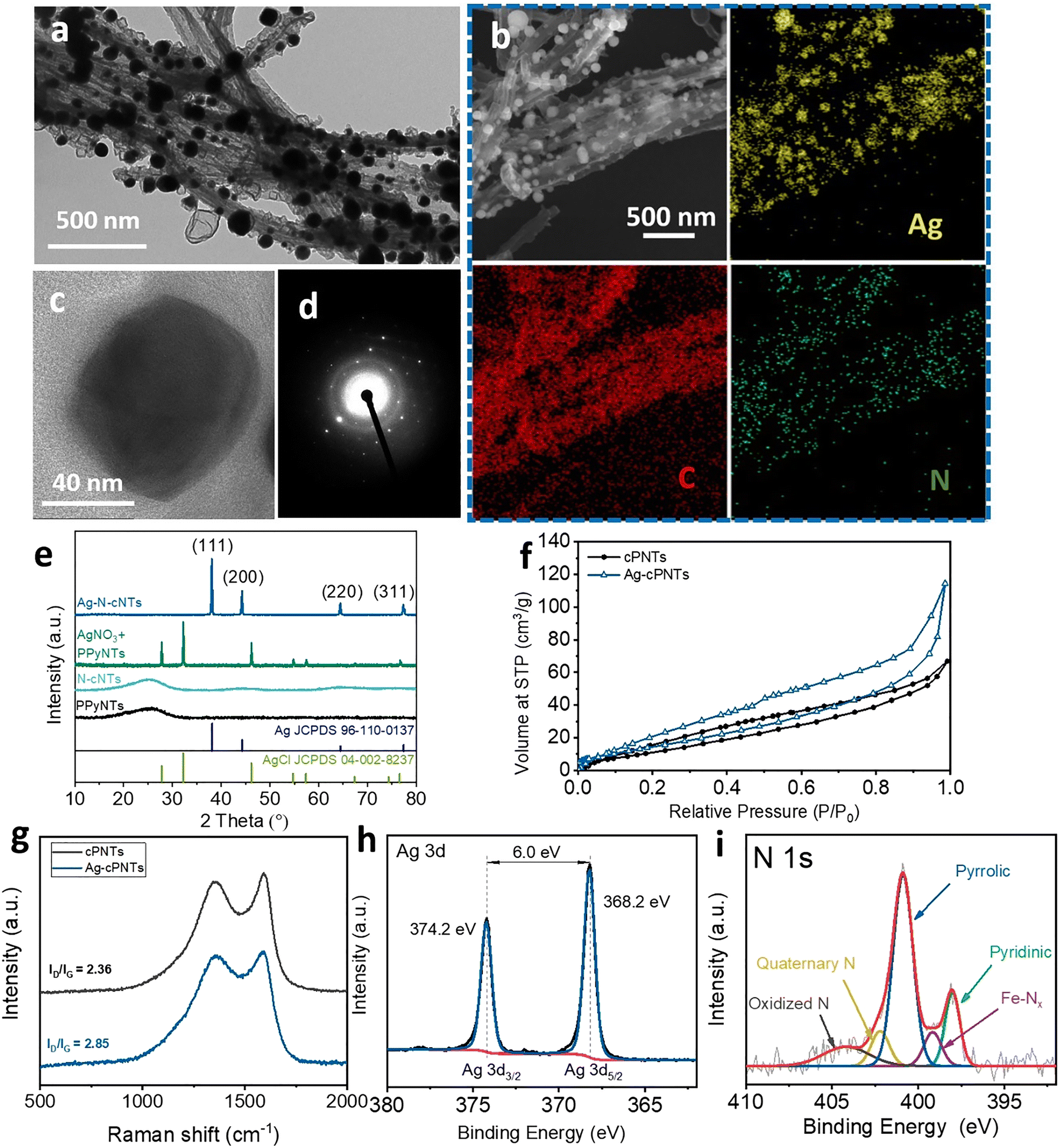 | ||
| Fig. 1 (a) TEM image of the Ag-cPNT catalyst; (b) SEM and SEM-EDX elemental mapping of Ag, C, and N; (c) HRTEM, (d) SAED pattern, and (e) XRD spectra of AgNP-decorated carbonized polypyrrole nanotubes (Ag-cPNTs) and PPyNTs mixed with AgNO3 and spectra of washed polypyrrole nanotubes (PPyNTs) and carbonized polypyrrole nanotubes (NTs); (f) nitrogen adsorption–desorption isotherms of PPyNTs and Ag-cPNTs; (g) Raman spectra of cPNTs and Ag-cPNTs measured at 532 nm; (h) Ag 3d and (i) N 1s and C 1s high-resolution XPS spectra of the Ag-cPNTs. | ||
The scanning electron microscopy with energy dispersive X-ray spectroscopy (SEM-EDX) indicated the presence and a homogeneous distribution of carbon and nitrogen, along with the discrete distribution of AgNPs across the surface of the material (Fig. 1b). SEM-EDX mapping also indicated the presence of iron, indicating its homogeneous distribution in the structure of Ag-cPNTs (Fig. S4, ESI†).
HRTEM analysis also confirmed the successful formation of AgNPs over the surface of cPNTs (Fig. 1c). An oriented layer of N-doped carbon was observed near the AgNP surface, confirming the composite nature of the material. Fig. 1d shows the selected area electron diffraction (SAED) image of Ag-cPNTs, in which the face-cubic structure of silver can be observed.
The successful formation of AgNPs was also confirmed by X-ray diffraction (XRD) (Fig. 1e). A typical pattern for AgNPs was observed as follows: 38.1°, 44.3°, 64.4° and 77.3° corresponding to the (111), (200), (220) and (311) planes of cubic Ag (JCPDS No. 96-110-0137). Characteristic peaks for AgCl were not observed, which confirms the complete reduction of Ag. For comparison, the XRD pattern of the precursor of a mixture of PPyNTs and AgCl, which forms as a result of adding AgNO3 to a solution containing Cl− ions, is shown below. Peaks at 27.8°, 32.2°, 46.2°, 54.8°, 57.5° and 76.7° were observed, which can be attributed to (111), (200), (220), (311), (222) and (420) planes of AgCl (JCPDS no. 04-002-8237).38 For control samples, PPyNTs and cPNTs, only wide amorphous peaks were observed, near 25.4°, which is typical for polypyrrole and carbonized nitrogen-doped carbon materials.39
Surface area and pore volume determinations from N2 adsorption/desorption isotherms confirmed significant changes. Brunauer–Emmett–Teller (BET) analysis revealed significant structural changes in the material after carbonization (Fig. 1f). As it is evident from the nitrogen adsorption–desorption isotherms, the type IV hysteresis loop indicated the presence of meso- and macropores in the Ag-cPNTs. The specific surface area and pore volumes, calculated by BET analysis and DFT models, were 61.9 ± 1.9 m2 g−1 and 0.120 ± 0.023 cm3 g−1 for Ag-cPNTs and 52.9 ± 2.2 and 0.084 ± 0.002 for cPNTs, respectively. The increase in the specific surface area can be attributed to the formation of a more disordered carbon structure due to the addition of silver nitrate, which, in turn, results in the development of nanofeatures on the Ag-cPNT surface.
Raman spectroscopy of carbonized cPNTs and Ag-cPNTs, performed using a 532 nm laser, showed two characteristic peaks of carbon related to 1591 cm−1 and 1355 cm−1, which are related to graphitic (G) and disordered (D) bands. The measurement of the ratio of integrated peaks also confirmed the increase of the disordered structure in Ag-cPNTs compared to cPNTs. The crystallinity degree, calculated using integrated intensities of D and G bands (ID/IG), was 2.36 for cPNTs and 2.85 for Ag-cPNTs (Fig. 1g).
To further investigate the structure and composition of the Ag-cPNTs, XPS analysis was performed. Fig. 1h shows the Ag 3d XPS spectrum of the Ag-cPNTs and the fitted two peaks at 368.2 and 374.2 eV, which are related to characteristic 3d 5/2 and 3d 3/2 peaks of metallic Ag, respectively. The difference in the binding energy between these two peaks is 6.0 eV, which is typical for Ag(0), confirming the metallic state of AgNPs in Ag-cPNTs. The fitted high-resolution C 1s spectrum revealed the presence of four peaks at about 284.7, 285.5, 286.7 and 290 eV, corresponding to C–C, C–N, C–O and C![[double bond, length as m-dash]](https://www.rsc.org/images/entities/char_e001.gif) O, respectively (Fig. S5b, ESI†). Deconvolution of the high-resolution N 1s peak indicated the presence of five nitrogen peaks, namely, pyridinic (398.0 eV), Fe–Nx (399.2 eV), pyrrolic –N–H (400.9 eV), graphitic (N+–H) (402.2 eV) and N-oxides (404.2 eV) (Fig. 1i). The survey XPS spectrum of the Ag-cPNT composite did now show the presence of Cl−, confirming the successful reduction of Ag NPs (Fig. S5a, ESI†).
O, respectively (Fig. S5b, ESI†). Deconvolution of the high-resolution N 1s peak indicated the presence of five nitrogen peaks, namely, pyridinic (398.0 eV), Fe–Nx (399.2 eV), pyrrolic –N–H (400.9 eV), graphitic (N+–H) (402.2 eV) and N-oxides (404.2 eV) (Fig. 1i). The survey XPS spectrum of the Ag-cPNT composite did now show the presence of Cl−, confirming the successful reduction of Ag NPs (Fig. S5a, ESI†).
In the next step, we determined the optical properties of the created materials. UV-Vis spectrophotometry showed the enhanced absorption properties of Ag-cPNTs compared to cPNTs (Fig. 2a). The appearance of wide, plasmon-related, absorption bands in the spectral range of 380–600 nm is evident for Ag-cPNTs. No such pronounced peak was observed for cPNTs. The position, width and plasmon-related nature of this peak were verified using TDFD calculations, performed taking into account the experimental results (size distribution of silver nanoparticles). As can be seen from the calculations (Fig. 2b), with an increase in the size of the nanoparticles, a red shift up to 550 nm of the plasmon absorption band occurs. Thus, the total absorption of the material can be explained by the excitation of plasmons on nanoparticles of different sizes, presented in the structure of Ag-cPNTs. The prepared material can efficiently absorb and convert into surface plasmons the light with short wavelengths from the visible spectrum (i.e. the most energetic photons). In turn, plasmon triggering can effectively activate both oxygen molecules and charge carriers in silver nanoparticles or closely aligned nanotubes.40–42 In the case of cPNTs, no pronounced peaks were observed, and the light transmittance gradually decreases with the increase of wavelength due to light scattering and the absorption increase.
 | ||
| Fig. 2 (a) Measured UV-Vis spectra of the carbonized polypyrrole nanotubes with (blue curve) and without AgNPs (red one); (b) calculated UV-Vis spectra of pristine AgNPs depending on their size; the inset shows the simulated photoexcited local plasmon-related electric field. | ||
In the next step, the material redox activity was studied by electrochemical measurements. First, the ORR catalytic activity was investigated by cyclic voltammetry (CV) measurements in N2- and O2-saturated 0.1 M KOH solutions at a scan rate of 50 mV s−1 without illumination (Fig. 3a). In the N2 saturated solution, CV curves demonstrated a rectangular-like shape without obvious redox peaks. In turn, when the electrolyte was saturated with O2, well-defined cathodic peaks, which indicate a significant reduction process, were observed at 0.65 V and 0.70 V vs RHE, for cPNTs and Ag-cPNTs, respectively. A more positive peak potential (Ep) indicates that Ag-cPNTs demonstrated superior ORR activity over cPNTs. In addition, from Fig. 3a it was obvious that Ag-cPNTs have both higher cathodic current density and more positive ORR peak potential. The area of the closed CV curve, which represents the electrochemical activity, is 2 times larger for Ag-cPNTs, compared to cPNTs. Based on the measurements, it can be concluded that both materials (Ag-cPNTs and cPNTs) are catalytically active toward the ORR, while the material containing AgNPs demonstrates superior catalytic properties.
 | ||
| Fig. 3 (a) Oxygen reduction voltammograms and CV curves of Ag-cPNTs and cPNTs in N2 (dotted line) and O2 (solid line)-saturated 0.1 M KOH solution (50 mV s−1); (b) LSV curves of irradiated (455 nm) and non-irradiated Ag-cPNTs (1600 rpm, 10 mV s−1); (c) calculated from LSV curves and Tafel plots; (d) LSV measurements of irradiated and non-irradiated Ag-cPNTs, performed at different rotation speeds; (e) increase in the current density at 0.40 V vs. RHE for different rotation speeds; (f) LSV curves of Ag-cPNTs in the dark and irradiated states at 455, 530, 660, and 780 nm. | ||
Next, plasmon-enhanced properties towards the ORR were demonstrated using a custom-made setup with a rotating disc electrode (RDE) (Fig. 4a). It was observed that under irradiation with a low power LED source (0.51 W cm−2) of wavelength 455 nm, an increase in current density from 3.6 mA cm−2 to 4 mA cm−2 and shift toward more positive potential occurred (Fig. 3b). The onset potential (Eonset) for the non-irradiated sample was 0.88 V vs. RHE, while under 455 nm illumination it increased to 0.9 V vs. RHE. Furthermore, under low-power LED illumination, the ORR half-wave potential (E1/2) showed a 12 mV shift to more positive values increasing from 0.650 V in the dark to 0.662 V. The calculated values of Tafel slopes for Ag-cPNTs showed their apparent decrease from 94 mV dec−1 to 87 mV dec−1 under plasmon triggering (Fig. 3c). The LSV curves recorded at various rotation speeds, both with and without illumination, are presented in Fig. 3d. From these data, Koutecký–Levich plots were obtained and using eqn (1)–(3), and transferred electron number of 3.52 was calculated, which indicates that oxygen reduction proceeds predominantly via the four-electron pathway, with a minor contribution from the two-electron route.
 | ||
| Fig. 4 (a) Schema of the custom-made electrochemical setup for plasmon-enhanced material properties; (b) chronoamperometric I–t measurements of the Ag nanoparticle-decorated N-doped carbonized polypyrrole nanotubes (Ag-cPNTs) with 455 nm LED light on and off; (c) methanol tolerance test; (d) possible mechanisms of AgNP-decorated N-doped carbon nanotubes. | ||
Other pyrrole to AgNO3 ratios, deviating from the optimal one, also resulted in lower performance in terms of catalytic activity, both with and without laser illumination. At lower ratios, the uneven distribution of silver particles led to less uniform coverage and showed the LSV profile similar to pristine cPNTs, while at higher ratios, a lower current density was observed (Fig. S6, ESI†). Under illumination, no statistically significant shift was observed in either the Eonset or the half-wave potential (E1/2). Illumination of the control cPNT samples did not produce a statistically significant increase in current density (Fig. S7, ESI†).
LSV measurements revealed that the change in current density upon irradiation of AgNPs remains approximately constant at 0.4 V vs. RHE across all tested rotation speeds. This indicates that plasmonic effects play a significant role in the electrochemical processes of our system and that their impact is not diffusion-limited (Fig. 3e). Illumination of the sample with other wavelengths also led to an increase in current density (Fig. 3f). The greatest enhancement in current density was observed at shorter wavelengths, specifically under illumination at 455 and 530 nm. Illumination with longer wavelengths (660 and 780 nm) resulted in less significant changes in the LSV curves due to the reduced contribution of these wavelengths to plasmon excitation (Fig. 2a). Fig. S8 (ESI†) presents the Tafel plots obtained from LSV curves, measured under illumination at different wavelengths. The strongest slope reduction at about 87 mV dec−1 is achieved with 455 nm light, which matches the plasmon-resonance maximum of the Ag nanoparticles.
Chronoamperometric measurements showed that upon LED illumination, the current density increased, confirming the plasmonic effect in the material. In particular, Fig. 4b demonstrates the I–t curve of Ag-cPNTs with periodic LEDs (455 nm) on and off. The increase of current density from −3.5 mA cm−2 to 4.1 mA cm−2 was observed immediately after illumination began, and the response time of the samples suggests that plasmon triggering is primarily an electron-related process rather than a plasmon-induced heating effect.
The timescale of the response to illumination indicates that fast electronic processes are occurring – specifically, direct photocatalysis with only a negligible contribution from thermally driven catalysis arising from plasmon-assisted heating.43 Further evidence comes from the response time itself: the system reacts within a few seconds – a timescale incompatible with a mechanism dominated by plasmon-induced heating.44,45
The significant increase in the redox activity of the Ag-cPNTs under illumination can be attributed to several mechanisms, which are schematically illustrated in Fig. 4d. First, plasmon excitation can lead to the direct activation of an oxygen molecule adsorbed onto the AgNP surface. A plasmon-excited hot electron occupies the antibonding orbital of the oxygen molecule, facilitating its dissociation and subsequent participation in the redox reaction.41,42 Alternatively, plasmon triggering can excite an inner electron of the oxygen molecule, leading to the occupation of an antibonding molecular orbital and destabilization of the oxygen molecule. Moreover, plasmon excitation generates a strong local electric field, which, in turn, can enhance the catalytic activity of nearby materials (in our case, cPNTs). The plasmon-induced electric field is expected to facilitate both the excitation of electron–hole pairs and their effective dissociation in cPNTs, generating redox-active charge carriers. In addition, the plasmon field can energetically enrich charge carriers, making them more redox active. In summary, plasmon triggering can directly enhance the catalytic activity of silver nanoparticles while also improving the activity of nearby nanotubes, both contributing to a significant increase in the overall catalytic performance of Ag-cPNTs.
The material stability was demonstrated both by SEM and Raman measurements after 500 ORR LSV cycles, indicating the stability of the prepared material (Fig. S9, ESI†). The preservation of AgNPs in the structure of the Ag-cPNT catalyst was observed, as well as only minor changes in Raman spectra. In addition to their high ORR activity, Ag-cPNTs exhibited immunity to methanol crossover (Fig. 4c). The methanol tolerance test performed was evaluated by chronoamperometry measurements. A sharp decrease in current density was observed in the case of the commercial Pt/C catalyst. We also compared our data with previously published results, and the key metrics: onset potential, current density, and illumination power density, are summarized in Table S1 (ESI†). In earlier studies, a noticeable increase in ORR current density was achieved only under illumination with high-power lasers (typically above 2 W cm−2). Our catalyst exhibited a clear and reproducible current increase with a simple low-power LED (0.51 W cm−2). For Ag-cPNTs, no changes in ORR current density were observed, confirming its great tolerance to methanol, which is important for durability and real-world fuel cell applications.
3. Conclusions
In this work, a plasmon-enhanced ORR catalyst based on AgNPs and N-doped carbon nanotubes was successfully prepared using a straightforward procedure. The created Ag-cPNT materials act as efficient ORR catalysts, which functionality can be enhanced under light illumination. Due to a wide distribution of AgNPs and creation of numerous plasmonic dimers and multimers, the created material was able to efficiently absorb light in the 380–600 nm wavelength range, with efficient excitation of surface plasmons. In particular, the strongest enhancement of both current density and potential shift toward more positive values during the ORR was demonstrated in the ORR regime under the illumination with a LED of 455 nm wavelength, which corresponded to a maximally efficient excitation of plasmon resonance. The response of the material to 530, 660, and 780 nm LED illumination was also observed. Both the materials, cPNTs and Ag-cPNTs, exhibit redox activity for the ORR. However, plasmon triggering significantly improves the ORR activity only for Ag-cPNTs. The time response of the material allows us to predict the “electronic” process in the enhancement of ORR kinetics. Such processes can proceed on the silver substrate through the injection of hot electrons in oxygen molecules or through the plasmon triggering of the redox activity of charge carriers in the nanotubes. Furthermore, Ag-cPNTs demonstrated great tolerance to methanol, which is essential for efficiency and durability in real-world applications. The demonstrated plasmon-induced hot electron enhancement strategy provides a promising pathway for boosting the efficiency of non-platinum ORR catalysts.4. Experimental section
4.1. Materials
Pyrrole monomers (97%) and silver nitrate AgNO3 were purchased from ABCR. Iron(III) chloride, methyl orange, and methanol were obtained from PENTA.4.2. Sample preparation
PPy nanotubes (PPyNTs) were prepared by oxidation polymerization of a pyrrole monomer in the presence of methyl orange (MO), as was previously reported.46 First, FeCl3 (0.243 g, 1.5 mM) was dissolved in 30 mL of 5 mM methyl orange solution. The solution was cooled to 4 °C in an ice bath. Then pyrrole (105 μL, 1.48 mM) was added to the solution under vigorous stirring. In several minutes, the solution became black, indicating the polymerization of pyrrole. Next, a certain amount of AgNO3 was added to achieve AgNO3 to pyrrole monomer molar ratios of 1:1, 2:1, and 4:1. The mixture was stirred in an ice bath and then at 25 °C for 24 h to complete polymerization. The precipitate was filtered and washed several times with distilled water and acetone. Finally, the PPyNTs with AgNO3 were carbonized under nitrogen flow using 5 °C min−1 heating to 900 °C under nitrogen flow and then cooled.
4.3. Material characterization
Transmission electron microscopy (TEM) was performed using a JEOL JEM-1010 transmission electron microscope, with a SIS MegaView III digital camera. Scanning electron microscopy (SEM) and scanning transmission electron microscopy (STEM) were performed using a Tescan Lyra3 GMU microscope at an acceleration voltage of 20 kV for Ag-cPNTs. The diameter of the nanotubes and particles was estimated using ImageJ software v1.52 using STEM and HRTEM images. X-ray diffraction data were collected on an XRD diffractometer PANalytical X’Pert PRO using Co Kα radiation (λ = 1.54 Å). Raman spectra were recorded using a dispersive Raman spectrometer (Thermo Scientific, model DXR Microscope, equipped with an Olympus confocal microscope). UV-Vis spectra were recorded using a Lambda 25 Spectrometer (PerkinElmer) in the 300–1100 nm wavelength range. The surface area and pore volume were determined from N2 adsorption and desorption isotherms (Quantachrome Instruments, NOVA3200) using NovaWin software. Five-point Brunauer–Emmett–Teller (BET) analysis was applied for the total surface area and DFT model for pore volume determinations. Each sample was measured four times with a relative experimental error of 5%. UV-Vis spectra were recorded using a Lambda 25 Spectrometer (PerkinElmer) in the 300–1100 nm wavelength range.4.4. Electrochemical characterization
Cyclic voltammetry (CV) measurements were performed in N2- and O2-saturated 0.1 M KOH solutions at a scan rate of 50 mV s−1 without illumination using a PalmSens4 potentiostat. The Pt wire and Ag/AgCl KCl saturated electrode were used as counter and reference electrodes, respectively. The suspension was prepared by ultrasonically mixing 6 mg of the sample, 10 μL of Nafion (5 wt%), and 300 μL of ethanol, followed by drop-casting 10 μL onto a 5 mm glassy carbon electrode, to achieve a catalyst loading of 1 mg cm−2. Rotating disk electrode measurements were performed using linear sweep voltammetry in a three-electrode system with a scan rate of 10 mV s−1. Measurements were performed in the dark or under illumination with 455, 530, 620, and 780 nm LEDs, and the power on the sample surface was adjusted to 0.51 W cm−2. The measured potentials were converted to the reversible hydrogen electrode (RHE) using the Nernst equation. The value of LED power was controlled using a Thorlabs optical power monitor. All measurements were performed at room temperature. All electrochemical measurements were performed at least five times to ensure reproducibility.The Koutecký–Levich equation was used for the calculation of the number of electrons in the ORR:
| 1/Jlim = 1/JLev + 1/JK | (1) |
| JK−1 = J−1 − (0.62·n·F·C0·(D0)2/3·ν−1/6·ω1/2)−1, | (2) |
485 C M−1), C0 is the oxygen concentration (C0 = 1.2 × 10⁻⁶ M cm−3), ν is the kinematic viscosity of the electrolyte (ν = 0.01 cm2 s−1), and ω is the rotation speed of the RDE.
The electron number occurring in the ORR, i.e.,
| n = 1/(0.62·K·F·C0·D2/3·ν−1/6), | (3) |
Data availability
The data presented in this study are available at https://zenodo.org/records/14889198.Conflicts of interest
There are no conflicts to declare.Acknowledgements
This work was supported by the Czech Science Foundation (GA CR) under project no. 22-25734S and by the Project OP JAK_Amulet, no. CZ.02.01.01/00/22_008/0004558, of the Ministry of Education, Youth and Sports, which is co-funded by the European Union.References
- W. Cheng, X. Zhao, H. Su, F. Tang, W. Che, H. Zhang and Q. Liu, Nat. Energy, 2019, 4, 115–122 CrossRef CAS.
- S. Samad, K. S. Loh, W. Y. Wong, T. K. Lee, J. Sunarso, S. T. Chong and W. R. Wan Daud, Int. J. Hydrogen Energy, 2018, 43, 7823–7854 CrossRef CAS.
- L. Lin, W. Zhou, R. Gao, S. Yao, X. Zhang, W. Xu, S. Zheng, Z. Jiang, Q. Yu, Y. W. Li, C. Shi, X. D. Wen and D. Ma, Nature, 2017, 544, 80–83 CrossRef CAS PubMed.
- X. Tian, X. F. Lu, B. Y. Xia and X. W. (David) Lou, Joule, 2020, 4, 45–68 CrossRef CAS.
- J. Hwang, K. Maharjan and H. J. Cho, Int. J. Hydrogen Energy, 2023, 48, 28629–28648 CrossRef CAS.
- X. F. Lu, B. Y. Xia, S. Q. Zang and X. W. Lou, Angew. Chem., Int. Ed., 2020, 59, 4634–4650 CrossRef CAS PubMed.
- S. Li, L. Shi, Y. Guo, J. Wang, D. Liu and S. Zhao, Chem. Sci., 2024, 15, 11188–11228 RSC.
- K. Jiao, J. Xuan, Q. Du, Z. Bao, B. Xie, B. Wang, Y. Zhao, L. Fan, H. Wang, Z. Hou, S. Huo, N. P. Brandon, Y. Yin and M. D. Guiver, Nature, 2021, 595, 361–369 CrossRef CAS PubMed.
- X. Wang, Z. Li, Y. Qu, T. Yuan, W. Wang, Y. Wu and Y. Li, Chem, 2019, 5, 1486–1511 CAS.
- C. Wan, X. Duan and Y. Huang, Adv. Energy Mater., 2020, 10, 1903815 CrossRef CAS.
- Y. Su, H. Jiang, Y. Zhu, X. Yang, J. Shen, W. Zou, J. Chen and C. Li, J. Mater. Chem. A, 2014, 2, 7281–7287 RSC.
- L. Zhang, X. Wang, T. Zhang, C. Liu, D. Li and S. Xing, J. Alloys Compd., 2019, 785, 491–498 CrossRef CAS.
- X. Wang, J. Zhang, P. Wang, L. Li, H. Wang, D. Sun, Y. Li, Y. Tang, X. F. Lu, Y. Wang and G. Fu, Energy Environ. Sci., 2023, 16, 5500–5512 RSC.
- Z. Y. Wu, X. X. Xu, B. C. Hu, H. W. Liang, Y. Lin, L. F. Chen and S. H. Yu, Angew. Chem., Int. Ed., 2015, 54, 8179–8183A CrossRef CAS PubMed.
- V. Vij, S. Sultan, A. M. Harzandi, A. Meena, J. N. Tiwari, W. G. Lee, T. Yoon and K. S. Kim, ACS Catal., 2017, 7, 7196–7225 CrossRef CAS.
- S. Li, X. Hao, A. Abudula and G. Guan, J. Mater. Chem. A, 2019, 7, 18674–18707 RSC.
- S. C. Lin, C. S. Hsu, S. Y. Chiu, T. Y. Liao and H. M. Chen, J. Am. Chem. Soc., 2017, 139, 2224–2233 CrossRef CAS PubMed.
- A. Holewinski, J. C. Idrobo and S. Linic, Nat. Chem., 2014, 6, 828–834 CrossRef CAS PubMed.
- Q. Wang, X. Cui, W. Guan, L. Zhang, X. Fan, Z. Shi and W. Zheng, J. Power Sources, 2014, 269, 152–157 CrossRef CAS.
- T. Van Cleve, E. Gibara and S. Linic, ChemCatChem, 2016, 8, 256–261 CrossRef CAS.
- S. M. Alia, K. Duong, T. Liu, K. Jensen and Y. Yan, ChemSusChem, 2012, 5, 1619–1624 CrossRef CAS PubMed.
- L. Zeng, T. S. Zhao and L. An, J. Mater. Chem. A, 2015, 3, 1410–1416 RSC.
- B. B. Blizanac, P. N. Ross and N. M. Markovic, Electrochim. Acta, 2007, 52, 2264–2271 CrossRef CAS.
- Y. Guo, M. Yang, R. C. Xie and R. G. Compton, Chem. Sci., 2021, 12, 397–406 RSC.
- S. Jin Kim, S. C. Lee, C. Lee, M. H. Kim and Y. Lee, Nano Energy, 2018, 48, 134–143 CrossRef.
- F. Shi, J. He, B. Zhang, J. Peng, Y. Ma, W. Chen, F. Li, Y. Qin, Y. Liu, W. Shang, P. Tao, C. Song, T. Deng, X. Qian, J. Ye and J. Wu, Nano Lett., 2019, 19, 1371–1378 CrossRef CAS PubMed.
- R. Elashnikov, K. Zahorjanova, E. Miliutina, Z. Kolska, M. Cieslar, V. Svorcik and O. Lyutakov, Nanoscale, 2020, 12, 12068–12075 RSC.
- W. Zhang, J. Li, X. H. Xia and Y. G. Zhou, Angew. Chem., Int. Ed., 2022, 61, e202115819 CrossRef CAS PubMed.
- J. Ding, F. Wang, F. Pan, P. Yu, N. Gao, R. H. Goldsmith, S. Cai, R. Yang and J. He, ACS Catal., 2021, 11, 13721–13732 CrossRef CAS.
- X. Lu, Z. Ma, Y. Chang, S. Wang, X. Li, D. Xu, J. Bao and Y. Liu, Adv. Mater., 2024, 36, 2313057 CrossRef CAS.
- A. Zabelina, E. Miliutina, D. Zabelin, V. Burtsev, V. Buravets, R. Elashnikov, V. Neubertova, M. Šťastný, D. Popelková, J. Lancok, S. Chertopalov, M. Paidar, A. Trelin, A. Michalcová, V. Švorčík and O. Lyutakov, Chem. Eng. J., 2023, 454, 140441 CrossRef CAS.
- D. Zabelin, A. Zabelina, E. Miliutina, A. Trelin, R. Elashnikov, D. Nazarov, M. Maximov, Y. Kalachyova, P. Sajdl, J. Lancok, M. Vondracek, V. Svorcik and O. Lyutakov, Chem. Eng. J., 2022, 443, 136440 CrossRef CAS.
- A. Zabelina, E. Miliutina, J. Dedek, A. Trelin, D. Zabelin, R. Valiev, R. Ramazanov, V. Burtsev, D. Popelkova, M. Stastny, V. Svorcik and O. Lyutakov, ACS Catal., 2023, 13, 10916–10926 CrossRef CAS PubMed.
- W. Liang, M. Xie, D. Li, W. Qin, C. Dai, Y. Wang, H. Zhang, B. Zhao, G. Jin, Y. Sun and L. Jiang, Angew. Chem., Int. Ed., 2024, 63, e202409484 CrossRef CAS PubMed.
- Q. Sun, X. H. Li, K. X. Wang, T. N. Ye and J. S. Chen, Energy Environ. Sci., 2023, 16, 1838–1869 RSC.
- A. Treshchalov, H. Erikson, L. Puust, S. Tsarenko, R. Saar, A. Vanetsev, K. Tammeveski and I. Sildos, J. Colloid Interface Sci., 2017, 491, 358–366 CrossRef CAS PubMed.
- Y. Lu, Y. Wang and W. Chen, J. Power Sources, 2011, 196, 3033–3038 CrossRef CAS.
- R. Dong, B. Tian, C. Zeng, T. Li, T. Wang and J. Zhang, J. Phys. Chem. C, 2013, 117, 213–220 CrossRef CAS.
- F. Su, C. K. Poh, J. S. Chen, G. Xu, D. Wang, Q. Li, J. Lin and X. W. Lou, Energy Environ. Sci., 2011, 4, 717–724 RSC.
- L. V. Besteiro, P. Yu, Z. Wang, A. W. Holleitner, G. V. Hartland, G. P. Wiederrecht and A. O. Govorov, Nano Today, 2019, 27, 120–145 CrossRef CAS.
- Y. F. Huang, M. Zhang, L. Bin Zhao, J. M. Feng, D. Y. Wu, B. Ren and Z. Q. Tian, Angew. Chem., Int. Ed., 2014, 53, 2353–2357 CrossRef CAS PubMed.
- C. H. Choi, K. Chung, T. T. H. Nguyen and D. H. Kim, ACS Energy Lett., 2018, 3, 1415–1433 CrossRef CAS.
- C. Zhan, B. W. Liu, Y. F. Huang, S. Hu, B. Ren, M. Moskovits and Z. Q. Tian, Nat. Commun., 2019, 10, 2671 CrossRef PubMed.
- G. Baffou, I. Bordacchini, A. Baldi and R. Quidant, Light: Sci. Appl., 2020, 9, 108 CrossRef PubMed.
- A. J. Bagnall, S. Ganguli and A. Sekretareva, Angew. Chem., Int. Ed., 2024, 63, e202314352 CrossRef CAS PubMed.
- R. Elashnikov, O. Khrystonko, T. Jilková, S. Rimpelová, J. Prchal, I. Khalakhan, Z. Kolská, V. Švorčík and O. Lyutakov, Adv. Funct. Mater., 2024, 34, 2314420 CrossRef CAS.
Footnote |
| † Electronic supplementary information (ESI) available. See DOI: https://doi.org/10.1039/d5ma00407a |
| This journal is © The Royal Society of Chemistry 2025 |