
 Open Access Article
 This Open Access Article is licensed under a
 Creative Commons Attribution 3.0 Unported Licence
Cellulose nanofibril-based hybrid coatings with enhanced moisture barrier properties†
Jingxuan
Zhang
 and
Jeffrey P.
Youngblood
*
and
Jeffrey P.
Youngblood
*
School of Materials Engineering, Purdue University, West Lafayette, IN 47907, USA. E-mail: zhan4128@purdue.edu; jpyoungb@purdue.edu
First published on 18th March 2025
Abstract
Cellulose nanomaterials have garnered significant attention as the next generation of environmentally friendly packaging materials because of their abundance, biodegradability, low density, superior mechanical properties, and excellent oxygen barrier characteristics. However, due to their hydrophilic nature, CNMs exhibit poor water barrier properties at high humidity conditions, which limits their potential applications. Our previous research has successfully incorporated CNF with CMC and coated the CNF/CMC coating on molded pulp trays for food packaging, but the barrier properties of CNF/CMC were weakened under high humidity conditions due to the hydrophilic nature of the coating and plasticization effect of the water molecules during the permeation process. In this study, we enhanced the water barrier properties of CNF-based coatings on molded pulp trays by chemically modifying the CNF through crosslinking with polyamide-epichlorohydrin (PAE), the incorporation of Cloisite-Na+ nano-clay, and the addition of polyvinyl alcohol (PVA). This formulation further improved the water vapor transmission rate (WVTR) in both wet-cup and dry-cup conditions, showing 40.5% in wet WVTR and 89.2% in dry WVTR values compared to unmodified CNF/CMC coatings. The chemical modification also helped enhance oxygen barrier performance, in which OP decreased from 6.48 × 10⁻¹⁵ cm3[STP] cm cm−2 s−1 Pa−1 to 2.31 × 10⁻¹⁵ cm3[STP] cm cm−2 s−1 Pa−1. A reduction in Cobb value from 137 ± 9 g m−2 to 56.3 ± 4.4 g m−2 was also observed. The formulated CNF-coated MP trays maintained the same #12 oil and grease resistance level as the unformulated ones. Mechanical testing proved that the formulated CNF coated tray samples showed 23.3% increase in ultimate tensile strength, 96.7% increase in strain at failure, but 37.6% decrease in Young's modulus. These results demonstrate that our chemically modified CNF coatings offer a promising sustainable alternative to conventional synthetic packaging materials, particularly for food packaging applications requiring enhanced barrier properties at high humidity conditions.
1. Introduction
The ubiquity of plastic products in modern society has led to a global environmental crisis, as discarded plastic items and microplastics accumulate in terrestrial and aquatic ecosystems, harming wildlife through entanglement, ingestion, and the leaching of harmful chemicals.1–3 While the convenience and low cost of plastics have made them indispensable, their durability and resistance to degradation have resulted in the widespread pollution of even remote environments.4As the environmental impacts of plastic pollution have become increasingly apparent, researchers have begun to explore alternative materials that might replace conventional plastics. One promising class of materials is cellulose nanomaterials (CNMs).5 CNMs exhibit unique physical and chemical properties, including high strength, low density, and biodegradability, which makes them attractive candidates for a wide range of applications.6–8 Unlike petroleum-based plastics, CNMs can be produced from renewable and sustainable feedstocks, offering a potential solution to the growing plastic waste problem.
Among the various types of CNMs, cellulose nanofibrils (CNFs) have garnered significant attention due to their exceptional mechanical properties and versatility.9 CNFs are typically produced through mechanical fibrillation or chemical pre-treatments followed by mechanical processing, resulting in high-aspect-ratio nanofibers with widths ranging from 4 to 20 nm and lengths ranging from 500 to 2000 nm.6,10 The high surface area and strong hydrogen bonding capabilities of CNFs allow for the formation of robust, interconnected networks that can impart strength and barrier properties.11 One of the most promising attributes of CNFs for packaging applications is their excellent oxygen barrier properties. This characteristic is particularly valuable in food packaging, where maintaining low oxygen transmission rates is crucial for preserving food quality and extending shelf life. Studies have demonstrated the effectiveness of CNFs in enhancing oxygen barrier properties.12 However, the oxygen barrier properties of CNFs drop sharply at relatively high humidity conditions due to the hydrophilicity of CNFs. Aulin et al.13 studied the oxygen barrier properties of micro fibrillated cellulose (MFC) free-standing films and coatings at different relative humidity (RH) at room temperature and found that the oxygen permeability (OP) of MFC films significantly increased at a RH higher than 70%. It was also found that the oxygen transmission rate (OTR) increased sharply above a moisture content of 15%. The water vapor transmission rate (WVTR) of CNFs is also high compared with most commercial polymers, and CNFs are considered a poor moisture barrier.12
Various approaches have been utilized to enhance the moisture barrier properties of CNFs. For example, Spence et al.14 studied the relationship of water adsorption, WVTR, and initial contact angle vs. lignin content and found that higher lignin content samples showed higher contact angles but worse water barrier performance at the same time. Although lignin is more hydrophobic than cellulose nanofibrils, high lignin content could also introduce more non-adsorbing large pores, therefore increasing WVTR values.
Besides incorporating more hydrophobic materials, much research has focused on modification of cellulosic nanomaterials to reduce WVTR by crosslinking. Hasan et al.15 reported crosslinked self-standing films of lignin-containing cellulose nanofibrils (LCNFs) derived from a recycled old, corrugated cardboard (OCC) pulp. Crosslinking was achieved by soaking in Al3+ or polyamidoamine epichlorohydrin (PAE) water bath. Results showed that both high humidity oxygen permeability and water vapor permeability was reduced for Al3+ and PAE cured LCNF, while PAE-cured samples were more pronounced, which could be due to reduced porosity, increased hydrophobicity from the PAE to the film, and the ester linkage. Furthermore, the researchers also applied cold and hot pressing during the film preparation, which could attribute to the increase in moisture and oxygen barrier performance. It has been found that PAE-crosslinked CNF showed a transition from hydrophilic to more hydrophobic.16,17
Apart from chemical crosslinking, addition of nano-sized clay could enhance the barrier properties against water vapor as impermeable filler particles create a more tortuous diffusion path for gas or water molecules.18 Tayeb et al.19 crosslinked CNFs using two crosslinking agents, PAE and Acrodur thermoset acrylic resin (ACR), and added colloidal montmorillonite nano-clay (MMT). Results showed that the synergistic effect of crosslinker and MMT substantially reduced the WVTR. Similarly, Khairuddin et al.20 reported a comparison study of applying different types of clay in starch and tested the water barrier performance. It was found that Cloisite-Na+, a sodium montmorillonite that can be well dispersed in water, showed the lowest WVTR among other types of nano-clay. Similarly, Farmahini-Farahani et al.21 utilized the Cloisite-Na+ nano-clay in microcrystalline cellulose and reported decrease in WVTR.
However, despite the notable decrease in WVTR of CNF after chemical crosslinking and the addition of nano-clay, it cannot be concluded that the internal pores have been minimized to their lowest possible extent. These remaining pores may continue to facilitate the transmission of water vapor. In other words, while the modifications have demonstrably improved the barrier properties, there is potential for further optimization of the CNF structure to minimize water vapor transmission. Therefore, additional polymers are needed to fill up the free volume and block the tunnels for water molecules to pass through. Polyvinyl alcohol (PVA) has long been recognized as a suitable candidate for food packaging due to its biodegradability, high oxygen barrier, good film-forming properties, etc. Most researchers focused on incorporating CNMs as fillers inside PVA matrix to improve the barrier performance,22–24 but very few explored the reverse approach. Chowdhury et al.25 incorporated CNC with PVA and discovered that the WVTR of CNC/PVA composite was lower than either pure CNC or pure PVA due to the lower free volume.
In this study, we propose an additive modified CNF coating using PAE as the crosslinker, Cloisite-Na+ as the nano-clay and PVA as the extra polymer for a premier combination. Molded pulp (MP) is chosen as a low-cost substrate as lidded tray are already used in short-term storage, but improvement in barrier properties could extend preservation ability. Water vapor transmission rate and oxygen permeation tests have shown that an improvement was achieved for the formulated CNF compared to the unmodified counterparts, and the contact angle measurements confirmed the hypothesis regarding the effect of each component on improving barrier performance, and SEM morphology test proved the increase of smoothness of the formulated CNF. Oil and grease resistance and food sauce stain resistance revealed that the formulated samples were at least equal to or potentially greater than the uncrosslinked CNF/CMC coated samples. Furthermore, the mechanical test showed that the Young's modulus decreased for the formulated CNF samples, but UTS and strain at break increased, and the formulated CNFs still had some degree of strength even completely soaked in water. While previous work on oil resistant coatings for paper has been established, to our knowledge, this is the first time that a waterproof, stain- and oil-resistant CNF coating with good water vapor barrier has been developed. While in this case it is for molded pulp, the concept of using polymer and clay additive, and crosslinker can be used on many other paper goods.
2. Experimental section
2.1. Materials
Mechanically fibrillated cellulose nanofibrils (CNFs) were purchased from the University of Maine, Orono, ME, USA (∼15%, ∼90% retained fines). Sodium carboxymethyl cellulose (CMC) (Lot #MKCK7917, average Mw ∼250![[thin space (1/6-em)]](https://www.rsc.org/images/entities/char_2009.gif) 000, degree of substitution 0.9), chitosan (Batch #04609LD, medium molecular weight), acetic acid (Lot # MKCL7705, glacial ReagentPlus®, ≥99%), toluene (product no, 244511, Lot #S HBH2498V, anhydrous, 99.8%), castor oil (product no, 259853, Lot # MKCP1892), polyvinyl alcohol (PVA) (Lot # MKCC9501, Mw 89000–98000, 99+% hydrolyzed), pectin from citrus peel (product no., P9135-100G, Lot #000311421), alginic acid sodium salt (180947-250G, Lot #1003666881), starch (product no, S9755-500G, soluble, ACS reagent), 1,2,3,4-butanetetracarboxylic acid (BTCA) (Lot # MKCC8769), citric acid (CA) (Lot # MKCG2579, ACS reagent, ≥99.5%), and sodium hypophosphite monohydrate (SHP) (≥ 99%) were purchased from Sigma-Aldrich. Ultrapure water was produced using a Barnstead Ultrapure water system. n-Heptane (product no., 32441, Lot # P11H726, spectrophotometric grade, 99+%) was purchased from Alfa Aesar. Polyamide epichlorohydrin (PAE, Polycup 9250, solid content = 25%) was kindly provided by Solenis LLC (Wilmington, DE). Cloisite-Na+ was kindly provided by BYK USA, Inc. (St Louis, MO).
000, degree of substitution 0.9), chitosan (Batch #04609LD, medium molecular weight), acetic acid (Lot # MKCL7705, glacial ReagentPlus®, ≥99%), toluene (product no, 244511, Lot #S HBH2498V, anhydrous, 99.8%), castor oil (product no, 259853, Lot # MKCP1892), polyvinyl alcohol (PVA) (Lot # MKCC9501, Mw 89000–98000, 99+% hydrolyzed), pectin from citrus peel (product no., P9135-100G, Lot #000311421), alginic acid sodium salt (180947-250G, Lot #1003666881), starch (product no, S9755-500G, soluble, ACS reagent), 1,2,3,4-butanetetracarboxylic acid (BTCA) (Lot # MKCC8769), citric acid (CA) (Lot # MKCG2579, ACS reagent, ≥99.5%), and sodium hypophosphite monohydrate (SHP) (≥ 99%) were purchased from Sigma-Aldrich. Ultrapure water was produced using a Barnstead Ultrapure water system. n-Heptane (product no., 32441, Lot # P11H726, spectrophotometric grade, 99+%) was purchased from Alfa Aesar. Polyamide epichlorohydrin (PAE, Polycup 9250, solid content = 25%) was kindly provided by Solenis LLC (Wilmington, DE). Cloisite-Na+ was kindly provided by BYK USA, Inc. (St Louis, MO).
Mixing cups and lids of 200 mL volume (Max 200 Cup – translucent, 501 220t) were purchased from FlackTek Inc., Landrum, SC, USA. Small Perm Cups (10 cm2, MO-1652) were purchased from Gardco, Columbia, MD, USA. Stainless steel meshes (“Dutch weave,” 316SS) with a mesh size of 165 × 800, and two temperature resistant silicone rubber sheets with a hardness of 60A were purchased from McMaster Carr Supply Company (Elmhurst, IL).
2.2. Preparation of CNF-based paste
The method of CNF-based paste preparation was the same as stated in previous literature.26 Large CNF chunks were first dried to around 20% solid concentration using a Memmert HCP 50 Humidity Chamber at 28.5 °C and 95% RH to achieve a homogeneous concentration. Then the CNF chunks were broken into small pellets using a blender. Later, 48 g of the 20 wt% CNF pellets were added into a 200 mL Flacktek mixing cup. CMC powders were added with the dry weight ratios of CMC to CNF of 1:10. Other components (crosslinker, nano-clay, extra polymers) were also added at specific weight ratios. The mixture was mixed using the SpeedMixer system (Flacktek Inc.) at 2000 rpm for 8 min and allowed to cool at room temperature for at least 10 min. For the second stage of mixing, the mixture was added into a high shear torque mixer (Plasti-Corder PL 2100 Electronic Torque Rheometer, C. W. Brabender, South Hackensack, NJ) equipped with Banbury-type mixing blades at a mixing speed of 120 rpm and temperature of 55 °C. A plateau in torque vs. time curve indicated a relatively homogeneous mixture had been achieved. The mixing generally requires 40 min to complete. The samples were collected and stored inside a refrigerator at 4 °C for future tests. Shorthand name of each formulation are given by weight ratios of contents. For example, a 10:1 dry weight ratio of CNF:CMC mixture is represented by 10CNF/1CMC.
2.3. Turbidity test
Procedures for turbidity were adopted from El Awad Azrak et al.27 with some modifications. Small specimens were taken from the CNF-based pastes containing different crosslinkers. The weight of each specimen was lower than 1 g for the convenience of characterization. The specimens were dried inside an oven at 90 °C for 2 hours, followed by drying at the corresponding cure temperature for 30 minutes for crosslinking. For each crosslinking strategy, a specimen was first diluted 100 times using DI water and stirred at 1000 rpm for 24 hours. Then, 100 µL of each supernatant was diluted with 17 mL of DI water. Finally, the suspensions were characterized by a nephelometric turbidimeter (Vernier®, Beaverton, OR). Before testing, the turbidimeter was calibrated using one cuvette containing 100 NTU standard and another cuvette containing only DI water (0 NTU). The diluted supernatant samples were added into the turbidity bottles and inserted inside the holder of the turbidimeter for testing. Turbidity values were recorded at 1 per second for 3 minutes.2.4. Preparation of formulated CNF dry sheets and coated MP trays
The process of making formulated CNF dry sheets and coated molded pulp (MP) tray was similar to previous literature with some modifications.26,28 The ∼20 wt% wet-formulated CNF-based pastes were first rolled into sheets 1 mm thick using a roller pin and a stainless steel sheet. Two 3D-printed rings were securely fixed at both ends of the rolling pin, with their inner diameters matching the outer diameter of the rolling pin. Each ring exhibited a thickness of 1 mm throughout its cross-section. The CNF-based wet sheets were then trimmed to desired shapes. For dry sheet making, the wet formulated CNF sheets were sandwiched between a series of different sheets. The structural composition, proceeding from the inner core to the outer shell, was arranged as follows: wet CNF sheets are positioned at the center, followed by stainless steel meshes (“Dutch Weave”), then layers of copy papers are applied, succeeded by rubber sheets, and finally enclosed by stainless steel plates, as shown in Fig. S1 (ESI†). Finally, the stacked layers were hot-pressed at 120 °C. During the hot-pressing process, the pressure gradually increased from 20 kPa to 60 kPa in 30 minutes to maintain the shape of CNF sheets and avoid over pressing. Before coating formulated CNF onto the MP trays, a few droplets of an aqueous primer solution, consisting of 2.5 wt% PAE, 2 wt% chitosan, 0.8 wt% acetic acid, were first smeared on the MP trays to increase the adhesion between the coating and substrate. Then the wet formulated CNF sheets were hand-coated onto the surface of trays as described in previous literature.26 Folds, wrinkles, and air pockets were flattened by hand, and a sharp blade was used to trim off the leftover sheet, leaving the edge of the trays uncoated. Then the wet samples were placed inside the 3D printed molds with air holes for drying. The molds were wrapped with rubber hands and placed in the oven for at 90 °C for 5.5 hours, followed by 120 °C for 30 mins.2.5. Water vapor transmission rate (WVTR) measurement
Water vapor transmission rate (WVTR) measures water barrier properties of samples by quantifying the mass of water vapor that passes through a unit area of the film in a given time. WVTR evaluations were performed using Gardco Inc.'s small permeation cups, following ASTM D1653-13 standards. The tests were conducted in both dry and wet conditions. For dry tests, approximately 4 g of desiccant was placed inside the cup, while wet tests used about 5 g of water instead. The bottom flat portion of the formulated CNF coated MP trays were cut into circular samples that were slightly larger than the cup opening for full coverage. Then the testing samples were secured between two O-rings and tightly screwed onto the cup, ensuring complete coverage. The cups were weighed daily. Both dry and wet tests were carried out at room temperature (23 °C) with 50% relative humidity.2.6. Oxygen permeability measurement
The oxygen permeability tests were conducted according to the procedures stated in the previous research.29–31 Briefly, the dry CNF-based sheets were cut into a circle with a diameter of 25 mm and then inserted into a stainless-steel holder with an exposed area of 3 cm2. The system was first evacuated for around 10 min to remove residual air and moisture, and then the valve connected to the bottom of the holder was shut off to prevent outer environment air from entering the holder. The leak rate, which is defined as the inevitable pressure rise rate in the downstream volume due to the leakage of the system, was measured in the first 12 hours. After that, the valve connecting the upper part of the sample holder was opened to let the oxygen enter the holder. The upstream pressure was set at around 50 psi. The test takes around 3 to 5 days. Eqn (1) shows how the permeability is calculated.32 | (1) |
2.7. Contact angle measurement
The contact angle test was performed using a drop shape analyzer (DSA) (Kruss DSA30) by the sessile drop method. The DSA was equipped with a high-resolution CCD camera, and the angles were measured using the ADVANCE software. CNF-based dry sheets were first cut into small rectangular specimens and then placed on the sample holder. About 2 µL of DI water was dropped onto the surface of the specimens. Images of water droplets on the surface of the specimens were taken. Due to the hydrophilic nature of the CNF-based samples, only the initial contact angles were taken. In this study, the initial contact angles were defined as the contact angles measured within 1 second after the water droplet touching the surface of the specimens.2.8. Surface characterization
A PerkinElmer Spectrum 100 FTIR spectrometer (ATR-FTIR) was used to characterize different formulations of the CNF-based samples.2.9. Cobb test
The Cobb test was performed to evaluate the sample's resistance to water penetration and to measure the amount of water absorbed per unit area. The test followed the TAPPI T441 om-09 standard, with some modifications due to size limitations. Before testing, the circular samples were conditioned at room temperature and 50% relative humidity for 24 hours, then weighed using an analytical balance. The samples were secured inside the perm cups in the same manner as in the wet perm cup WVTR test described earlier. The perm cups were placed upside down to allow the water to contact the CNF-based coating, and a stopwatch was used to track the time. After 120 seconds, the perm cups were returned to their normal position, and the samples were removed and gently wiped with blotting paper to remove excess water. The samples were then reweighed, and the Cobb values were calculated.2.10. Oil and grease resistance
Oil and grease resistance tests were conducted according to the TAPPI T559 standard. Twelve vials containing a mixture of castor oil, toluene, and n-heptane were prepared in predetermined ratios, with kit 1 being the least aggressive and kit 12 the most aggressive. A single drop of the oil mixture was dropped to the surface of the CNF-based coatings, left for 15 seconds, and then quickly wiped off with a tissue. The test area was visually inspected to check for any darkening. Darkening indicated a failure, while no change in appearance indicated a pass. If the sample failed, testing was repeated with a lower kit number oil; if it passed, a higher kit number oil would be used for the next test. This process continued until the highest-numbered kit solution that the coating could pass was identified, which became the coating's kit rating.2.11. Sauce stain resistance testing of coated MP trays
To evaluate the practical application of formulated CNF-coated MP trays, a sauce stain resistance test was conducted. The experiment involved food sauces to the surface of the formulated CNF-coated MP trays. Ketchup and yellow mustard were purchased from a local grocery store and used for testing. First, about 5 g of sauce was applied to the bottom part of the tray. After a 30-second interval, the sauces were wiped off using paper towels. Color comparisons of the tray surfaces before and after sauce application were performed via visual inspection. Additionally, uncoated MP trays and CNF/CMC-coated MP trays were subjected to identical testing procedures, serving as control groups for comparative analysis.2.12. Mechanical test procedure
A uniaxial tensile test was performed to characterize the mechanical properties of the CNF-based coating before and after chemical modifications using a TA.XTplusC Texture Analyzer (Stable Micro Systems, Godalming, United Kingdom). The CNF-based dry coating sheets and coated MP trays were first cut into dog-bone specimens using a steel rule die made by ACE Steel Rule Dies (Medford, NJ) following ASTM D6438 Type IV standard. Unless stated otherwise, the dimensions were measured by a digital caliper (Fisherbrand™ Traceable™) or a micrometer (Mitutoyo Corporation). The dog-bone sample has a total length of 60 mm, neck width of 4.80 mm, and gauge width of 12 mm. The thickness of the dry coating sample was around 200 µm, and thickness of the coated MP trays was around 1.7 mm. The specimens were first preconditioned at room temperature and 10% RH for a day. Sandpapers were used between the grips and specimens to avoid slippage. The crosshead speed was set at 1 mm min−1. The ultimate stress was taken from the highest stress before break, strain is calculated from the crosshead displacement, and the modulus is calculated using the steepest slope method. For formulated CNF-based coatings, wet strength of the coatings were also tested. The dog-bone specimens were first soaked inside the DI water for 4 hours followed by the uniaxial tensile test. The samples were lightly pressed with blotting paper to remove excess water before testing. The testing procedure is the same as the one for dry specimens.3. Results and discussion
3.1. Turbidity and FTIR
Common crosslinking agents for cellulose nanofibrils (CNFs) include polycarbodiimide (CDI), 1,2,3,4-butanetetracarboxylic acid (BTCA), citric acid (CA), and polyamide epichlorohydrin (PAE). We first screened crosslinkers for a CNF/CMC formulation to determine which provided the best properties. Our previous work has shown that CMC exhibits a strong affinity for adsorption onto the surface of CNF and has a preferred weight ratio of CNF to CMC was 10:1.27,33 The CMC acts to allow molding, extrusion and very high solids content by colloidally stabilizing the CNF. Our previous work on MP coatings used CNF/CMC and for all work here, this material was used.
CDI requires acidic conditions to be activated for crosslinking. The crosslinking process for CNF cords can be effectively accomplished by immersion in an acidic solution, thereby meeting the requisite conditions.27 However, when copious quantities of CNF paste balls are to be prepared, a prolonged immersion period in acidic solution post-preparation is necessitated. The diffusion of acid within CNF paste balls may not be homogeneous. Consequently, a concentration gradient is likely to be established between the surface and the interior of the paste balls. Alternatively, the introduction of acidic components during the mixing process may be considered. However, this approach is also potentially problematic as corrosive effects on the stainless-steel mixing vessel itself may be induced. Furthermore, in the context of CNF application as a coating material for molded pulp trays, it is deemed preferable to utilize the material under neutral conditions.
BTCA and CA are polycarboxylic acids that are commonly used to crosslink cellulose via esterification reaction. Sodium hypophosphite (SHP) has proven to be an efficient catalyst for the reaction. In the presence of SHP, BTCA or CA may form cyclic anhydride at temperatures lower than the melting point by weakening the hydrogen bonds.34 Later, SHP may react with the intermediate of the anhydride to esterify the cellulose.35 Guo et al.36 investigated the effects of varying weight ratios between CNF and BTCA and revealed that a weight ratio of 10:1 (CNF:BTCA) was optimal for the intended application, and the amount of SHP was the same of BTCA. Similar research was conducted by Dinesh et al.37 revealed that a 10:1 ratio of CNF to CA showed the highest degree of crosslinking. Therefore, in this study, a 10:1 weight ratio of CNF to BTCA or CA was applied, and the weight of SHP was the same as the polycarboxylic acid in each formulation.
PAE is another common crosslinker in the papermaking industry. The primary mechanism of PAE crosslinking with cellulose is attributed to the ester bond formation between carboxyl groups on cellulose and azetidinium groups of PAE, as shown in Fig. S2 (ESI†).38 There is also a secondary mechanism of homo-crosslinking of PAE itself,39–41 where the carboxyl end group on one polymer chain reacts with the secondary amine group on another chain and forms crosslinking network.42–44 It has been discovered that in the interactions between PAE and cellulose, a dual crosslinking mechanism was evident.19 The self-crosslinking involves azetidinium groups crosslinking with the carboxyl groups and primary amino groups, as well as the secondary amine on the backbone. This self-crosslinking phenomenon results in the formation of a water-insoluble network structure and further increases mechanical performance. However, the degree of biodegradability and the repulping ability of cured cellulose would be decreased if too much PAE had been used. Therefore, the utilization of PAE is typically minimal, with dosages generally constituting approximately 1% of the cellulose dry weight. 1.5% PAE was used based on the previous literatures and reports.15,17,19 Despite this relatively low concentration, the crosslinking was observed to be highly effective.
FTIR analysis was conducted on CNF samples crosslinked with BTCA, CA, and PAE respectively to verify the occurrence of crosslinking, and pure CNF and CNF/CMC mixture were also tested as control groups. 10CNF/1CMC/1BTCA/1SHP, 10CNF/1CMC/1CA/1SHP, and 100CNF/10CMC/1.5PAE were tested. 10CNF/1CMC and pure CNF were also tested as control groups. Fig. 1 shows the FTIR of the formulations. Peaks at 3338 cm−1 (O–H stretching), 2902 cm−1 (C–H stretching), and 1642 cm−1 (O–H bending) were observed among all five CNF-based samples, which are characteristic peaks for CNFs.42,43 Peaks at 1594 cm−1 were due to the asymmetric stretching vibration of the carboxylate (COO–) moiety,27,44 and this peak was observed in all samples with CMC except the CA crosslinked, which could be attributed to the masking by the adjacent peaks at 1642 cm−1. Peaks at 1726 cm−1 for BTCA crosslinked and CA crosslinked samples and peak at 1742 cm−1 for PAE crosslinked samples were attributed to C![[double bond, length as m-dash]](https://www.rsc.org/images/entities/char_e001.gif) O ester bond stretching vibration.15,19,36–38,45 For BTCA crosslinked and CA crosslinked samples, the esterification reaction happened between the hydroxyl groups on cellulose and the carboxylic groups on the polycarboxylic acids (BTCA or CA). For PAE crosslinked sample, the esterification occurs between the carboxyl groups and azetidinium groups of PAE. It is normal for these ester groups to have different wavenumbers. Furthermore, a subtle inflection point was observed at 1558 cm−1 for PAE crosslinked sample. This feature could potentially be attributed to the amide(II) band absorbance.19 However, its visibility was diminished due to the intensity of adjacent absorption peaks. Nevertheless, the emergence of the ester absorption peak provides evidence for the formation of crosslinking.
O ester bond stretching vibration.15,19,36–38,45 For BTCA crosslinked and CA crosslinked samples, the esterification reaction happened between the hydroxyl groups on cellulose and the carboxylic groups on the polycarboxylic acids (BTCA or CA). For PAE crosslinked sample, the esterification occurs between the carboxyl groups and azetidinium groups of PAE. It is normal for these ester groups to have different wavenumbers. Furthermore, a subtle inflection point was observed at 1558 cm−1 for PAE crosslinked sample. This feature could potentially be attributed to the amide(II) band absorbance.19 However, its visibility was diminished due to the intensity of adjacent absorption peaks. Nevertheless, the emergence of the ester absorption peak provides evidence for the formation of crosslinking.
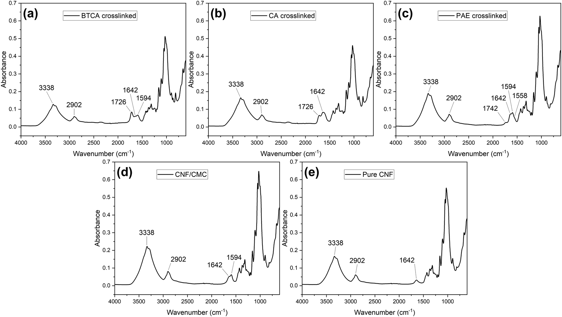 | ||
| Fig. 1 FTIR curved of the (a) BTCA crosslinked, (b) CA crosslinked, (c) PAE crosslinked, (d) CNF/CMC, and (e) pure CNF. | ||
To compare different crosslinkers and further prove that crosslinking has occurred, a turbidity test was conducted. Turbidity measurements can be employed as an effective method to assess the extent of crosslinking in CNF systems. As the crosslinking process progresses, a discernible decrease in turbidity is typically observed. This reduction can be attributed to the formation of a three-dimensional network structure, which also proves the successful crosslinking. Table 1 shows the turbidity values for different crosslinking methods. The PAE-crosslinked samples showed the lowest turbidity values even at a relatively low weight ratio of 100:1.5 (CNF vs. crosslinker) compared to BTCA and CA. Also, when crosslinking with CNF, BTCA or CA generally requires higher temperatures35 (140 °C or higher) for the esterification reaction. PAE can crosslink at lower temperatures, often around 80–120 °C. PAE forms covalent bonds with cellulose through its azetidinium groups, which are more reactive than the carboxylic acid groups of BTCA and thus require less thermal energy to initiate the crosslinking reaction.
| Sample | CNF/CMC | BTCA crosslinked | CA crosslinked | PAE crosslinked |
|---|---|---|---|---|
| Turbidity (NTU) | 27.41 ± 0.34 | 4.86 ± 0.03 | 5.23 ± 0.03 | 1.90 ± 0.08 |
Furthermore, BTCA-, CA-, and PAE-crosslinked CNF coated MP trays were compared visually, as shown in Fig. S3 (ESI†). The varying crosslinking temperatures resulted in discernible differences in the coloration of the coating surfaces. The coatings crosslinked with BTCA and CA were found to exhibit a notably more pronounced brown hue compared to those crosslinked with PAE. From an aesthetic perspective for food packaging applications, the PAE-crosslinked coatings were determined to be superior to the other two alternatives. Therefore, PAE was selected as the crosslinker for CNF/CMC.
3.2. Formulation of CNF systems to improve barrier performance
In the previous section, PAE was selected as the crosslinker for CNFs. However, although crosslinking prevents the dissolution of CNF under high humidity conditions, this does not indicate that relying solely on crosslinking to enhance water barrier performance is sufficient. Hence, a variety of formulations were screened by incorporation of nano-clay to increase tortuosity and water-soluble polymers to reduce free volume. As the main issue with CNF-based packaging is water transport, “wet cup” WVTR at high humidity (100% to 50% gradient) was used as a screening metric.Unfunctionalized montmorillonite (MMT) is one of the most prevalent forms of nano-clay. However, unfunctionalized MMT requires exfoliation to disperse into nanosheets, otherwise its ability of enhancing barrier performance would be greatly reduced due to agglomeration. Common methodologies include freezing/thawing and ultrasonic exfoliation.46 Nevertheless, even in water suspensions of exfoliated MMT, a stable mass percentage typically does not exceed 1 wt%. Tayeb et al.19 prepared a 1 wt% MMT water suspension by sonication. The MMT suspension and PAE were separately added to 1 wt% CNF, and the film was made by solvent casting. Unfortunately, higher contents are difficult as MMT can easily aggregate in high-concentration suspensions, even after being exfoliated leading to poor moisture barrier performance. Initial testing of MMT and Cloisite-Na+ was performed where Cloisite-Na+ showed better overall dispersion and stability at both high and low concentration. Thus, Cloisite-Na+ was chosen to be used. Previous researchers have also studied the proper range of nano-clay concentration in CNF matrix. Shanmugam47 prepared the CNF/Cloisite-Na+ composites with different weight ratios and tested the water vapor permeability of the films. It was found that the WVTR value increased as the nano-clay concentration increased up to 5 wt%, where aggregation occurred. The onset concentration started at 5 wt%, meaning that the aggregation might have happened when the nano-clay concentration exceeded 5 wt%. Similarly, Farmahini-Farahani et al.21 also tested the water vapor permeability (WVP) of regenerated cellulose/Cloisite-Na+ nanocomposite films. It was found that the WVP started to plateau at 3 wt% of Cloisite-Na+ to cellulose, showed a slight decrease at 5 wt%, and increased again at 10 wt%. In these two studies, the weight percentage was defined as the percentage of nano-clay based on cellulose. Therefore, in order to investigate the optimal Cloisite-Na+ concentration for current study, the water barrier performance tests for PAE-crosslinked CNF with different Cloisite-Na+ concentration based on previous work (3 wt% and 5 wt% based on the CNF) were tested. Table 2 showed the WVTR values for the coated MP trays with different formulations. A T-test was conducted, and the results showed that WVTR values of the 3 wt% Cloisite-Na+ sample were statistically lower than the 5 wt% Cloisite-Na+ sample at α = 0.05. This difference may be due to the PAE-crosslinked CNF system. The crosslinked 3D network structure made it harder for the nano-clay to be well dispersed in the CNF matrix compared to the un-crosslinked CNF system. This led to a shift in the threshold concentration for nano-clay aggregation. Consequently, under the current conditions, the 3 wt% formulation exhibits superior water vapor barrier performance to the 5 wt% formulation.
| Samples (weight ratio) | WVTR [g m−2 day−1] |
|---|---|
| 100CNF/10CMC/1.5PAE | 588.7 ± 30.8 |
| 100CNF/10CMC/1.5PAE/3Cloisite-Na+ | 528.8 ± 19.7 |
| 100CNF/10CMC/1.5PAE/5Cloisite-Na+ | 557.4 ± 23.1 |
In addition to chemical crosslinking and the incorporation of nano-clays, the barrier performance of CNF can also be enhanced by introducing other polymers into the system. Researchers have found that the water barrier performance improved when incorporating CNF to hydrophilic polymers polyvinyl alcohol (PVA).22–24,48 Although both components are hydrophilic materials, the composite showed better water barrier performance after mixing than any single component alone. Similarly, we hypothesize that when CNF serves as the matrix when it is at high content, it also contains numerous internal pores. Extra polymers, even as a minor component, will contribute to a lower WVTR. Previously, we have shown that the addition of polymer can enhance oxygen barrier by a similar method in CNC.29 As the maximum benefit was observed at 10% polymer, such was used here during screening. The results of WVTR values of crosslinked, nano-clay incorporated CNF-based coated trays with different polymers are shown in Table 3. It was found that the PVA showed statistically significant lower values compared to the other three samples, while the other three groups showed almost the same results as the one without extra polymers. This phenomenon could be due to multiple reasons. First, compared to other polysaccharides, PVA is much harder to dissolve in water at room temperature. Therefore, at room temperature and high humidity conditions, the degree of swelling of PVA might be lower compared to other polymers, therefore creating much less new free volume due to plasticization. Also, PVA is known to have good film-forming abilities which may simply improve the structure of the film (i.e. less pinholes, fisheyes, etc.).24,49
| Samples (weight ratio) | WVTR [g m−2 day−1] |
|---|---|
| 100CNF/10CMC/1.5PAE/3Cloisite-Na+/10PVA | 466.9 ± 14.7 |
| 100CNF/10CMC/1.5PAE/3Cloisite-Na+/10starch | 527.6 ± 20.1 |
| 100CNF/10CMC/1.5PAE/3Cloisite-Na+/10pectin | 503.1 ± 14.9 |
| 100CNF/10CMC/1.5PAE/3Cloisite-Na+/10alginic acid | 525.2 ± 12.4 |
| 100CNF/10CMC/1.5PAE/3Cloisite-Na+ | 528.8 ± 19.7 |
Consequently, 10 wt% PVA was incorporated into the PAE-crosslinked CNF formulation containing 3 wt% Cloisite-Na+. The wet cup WVTR of MP trays coated with this formulation was subsequently measured. To demonstrate the effects of each component, a series of control groups were also tested. The results of wet-cup and dry-cup WVTR values are shown in Table 4. It was evident that the addition of the PVA external polymer further reduced the WVTR by around 65 g m−2 day−1. The WVTR values for the PAE crosslinked CNF with only nano-clay or PAE showed statistical difference to the value of PAE crosslinked CNF with both nano-clay and PAE, meaning that both nano-clay and PAE contributed to reduced WVTR. Therefore, the formulation of 100CNF/10CMC/1.5PAE/3Cloisite-Na+/10PVA, comprising PAE as crosslinker, Cloisite-Na+ as the nano-clay to create tortuous paths for water vapor diffusion, and PVA as extra polymer to further reduce free volume, was established. Henceforth, unless otherwise specified, this formulation will be referred to as “formulated CNF”. Interestingly, water contact angle analysis showed that while crosslinking led to an increase in contact angle indicating that PAE made the material less hydrophilic, addition of clay, polymer and clay/polymer steadily made the contact angle decrease indicating an increase in hydrophilicity. While normally this may mean higher WVTR, in this case the increased tortuosity and lower free volume counteracts it. The results are shown in Fig. S4 and Table S1 (ESI†).
| Samples (weight ratio) | WVTR (wet) [g m−2 day−1] | WVTR (dry) [g m−2 day−1] |
|---|---|---|
| 100CNF/10CMC | 784.6 ± 21.9 | 36.1 ± 1.6 |
| 100CNF/10CMC/1.5PAE | 588.7 ± 30.8 | 9.7 ± 1.7 |
| 100CNF/10CMC/1.5PAE/3Cloisite-Na+ | 528.8 ± 19.7 | 5.3 ± 0.8 |
| 100CNF/10CMC/1.5PAE/10PVA | 519.3 ± 25.0 | 4.9 ± 0.6 |
| 100CNF/10CMC/1.5PAE/3Cloisite-Na+/10PVA | 466.9 ± 14.7 | 3.9 ± 0.2 |
The significantly lower dry cup WVTR values compared to wet cup values are to be expected due to lack of humidity plasticization. During wet cup testing, the coating faces an environment of 100% RH on one side and 50% RH on the external side, resulting in considerable moisture adsorption by the coating itself. Although the 3D network structure created by PAE crosslinking prevents the coating from dissolving, swelling still occurs, leading to increased free volume. Conversely, in dry cup testing, the coating faces 0% RH, and the absence of water molecules' plasticizing effect results in lower porosity. This difference in moisture exposure and its consequent effects on the coating's structure account for the observed disparity in WVTR values between wet and dry cup tests. Similarly to the wet WVTR testing, the formulated CNF-coated tray samples showed statistical lower WVTR values compared to other samples.
As the formulation has been decided during the WVTR tests, the oxygen permeability (OP) tests were conducted on formulated CNF (100CNF/10CMC/1.5PAE/3Cloisite-Na+/10PVA) and CNF/CMC only. Due to the limitations of sample thickness for OP tests, the test specimens were dry sheets of pure coatings instead of coated MP trays. The test was conducted at room temperature and 0% RH. The results showed that the OP of formulated CNF was 2.31 × 10⁻¹⁵ cm3[STP] cm cm−2 s−1 Pa−1, and OP value for the unformulated CNF/CMC was 6.48 × 10⁻¹⁵ cm3[STP] cm cm−2 s−1 Pa−1., which was almost the same as pure CNF OP value reported by Chowdhury et al.,31 which was 6.49 × 10⁻¹⁵ cm3[STP] cm cm−2 s−1 Pa−1, meaning that the addition of CMC did not change the oxygen barrier properties of CNFs. Some degree of reduction in OP was observed, which could be attributed to a reduction in the free volume. CNFs have long been known as good oxygen barrier materials due to their hydrophilicity, which impedes the adsorption and desorption of oxygen molecules during the permeation process.
3.3. Cobb test and oil and grease resistance
The Cobb test was conducted to evaluate the ability of water penetration resistance by measuring the amount of water absorbed over a specific amount of time. The uncoated MP tray, CNF/CMC coated MP trays, and the formulated CNF coated MP tray were tested. Results showed that the water absorbency of the uncoated MP tray was 154 ± 11 g m−2, the value for CNF/CMC coated MP trays was 137 ± 9 g m−2, and the formulated CNF coated MP tray exhibited a significantly lower value of 56.3 ± 4.4 g m−2. This substantial reduction in water absorbency demonstrates the effectiveness of the formulated CNF coating in enhancing the water resistance of the MP tray. One aspect that also must be stated is that this test is over relatively short exposure times. The CNF/CMC material is known to completely redisperse with time due to its low inter-fiber cohesiveness resulting from its high charge state. Thus, over a longer time, the CNF/CMC will completely come off, while we expect the formulated material will not.The oil and grease resistance test aims to evaluate the material resistance and barrier performance against oils and grease. This test is primarily applicable to packaging materials, food containers, and other products that meet oils and greases. The oil and grease resistance of the formulated CNF coated tray was evaluated using the TAPPI T559 kit test method. The results were shown in Fig. 2. After a kit #12 level oil test, it was observed that the formulated CNF coated MP tray sample did not exhibit any notable changes via visual inspection before and after the testing, indicating that it passed the kit #12 level, which was the same level of performance as the CNF/CMC coated MP tray in the previous research.26 This indicates that the formulated CNF coating also provided effective barrier properties against oil and grease penetration. However, due to the limitation of the testing standard, the highest kit number is 12. The SEM images and water contact angle test have shown that formulated CNF coatings are less porous and more hydrophobic than the unmodified CNF/CMC coating, therefore, it is reasonable to speculate that the formulated CNF coatings might have even better oil and grease resistance than the CNF/CMC ones. Regardless, a kit of 12 typically needs totally impermeable materials such as plastic films or PFAS coatings for paper. Thus, all coatings show PFAS-type performance using a mostly natural formulation of non-toxic, biodegradable food-safe components.
 | ||
| Fig. 2 Oil and grease resistance testing for uncoated MP tray, CNF/CMC coated MP tray, and formulated CNF coated MP tray samples. (a) Uncoated tray for test kit level 1 before testing. (b) Uncoated tray for test kit level 1 after testing. (c) CNF/CMC coated tray for test kit level 12 before testing. (d) CNF/CMC coated tray for test kit level 12 after testing. (e) Formulated CNF coated MP tray for test kit level 12 before testing. (f) Formulated CNF coated MP tray for test kit level 12 after testing. (a)–(d) Are reprinted with permission from Zhang, J.; Youngblood, J. P. Cellulose Nanofibril (CNF)-Coated PFAS-Free, Grease-Resistant All-Bio-Based Molded Pulp Containers for Food Packaging. ACS Appl. Polym. Mater., 2023, 5(7), 5696–5706. Copyright 2024 American Chemical Society. | ||
3.4. Sauce stain test
To evaluate the real-life performance of the formulated CNF coated MP tray as food containers, a sauce stain test was conducted. Fig. 3 and 4 showed the results of the test. It can be easily seen that both sauces left a stain on the uncoated MP trays, but not on CNF/CMC coated MP trays or the formulated CNF coated trays. However, turbidity testing has proven that the CNF/CMC coating could be dissolved in water, and the CNF/CMC coated trays showed higher Cobb value than the formulated CNF coated ones as well. Therefore, it can be postulated that, over an extended period, residual marks are likely to occur on the CNF/CMC coated trays. | ||
| Fig. 3 Ketchup stain test. From top to bottom were uncoated MP trays, CNF/CMC coated MP trays, and formulated CNF coated trays. From left to right there were trays before testing, during testing, and after testing. | ||
 | ||
| Fig. 4 Yellow mustard stain test. From top to bottom were uncoated MP trays, CNF/CMC coated MP trays, and formulated CNF coated trays. From left to right there were trays before testing, during testing, and after testing. | ||
3.5. Mechanical performance
As mechanical performance can be a criterion for rigid trays, uniaxial tension tests were conducted both CNF-based dry sheets and coated samples, and results were compared with the uncrosslinked counterparts. The thickness of the coatings was about 0.2 mm, and the thickness of the uncoated MP trays was about 1.5 mm. Tables 5 and 6 showed the mechanical test results CNF-based dry sheets and coated MP trays. Detailed stress vs. strain curves were shown from Fig. S5–S8 (ESI†). For the It was observed that the Young's decreased around 50% after PAE-crosslinking, but the UTS was similar to uncrosslinked 10CNF/1CMC dry sheet, and strain-at-break increased. To explain this, we propose a hypothesis. After PAE crosslinking, the positions of fibers within the CNF structure are presumed to be more fixed than in the pre-crosslinked state. For uncrosslinked 10CNF/1CMC, all fibers are expected to show some degree of orientation in the direction of applied tension when being stretched. In this case, the Voigt model (axial loading model) fits this condition better. However, after crosslinking, the degree of fiber orientation may be diminished due to constrained movement, potentially resulting in a reduction in the number of fibers bearing the tensile load within the elastic deformation region. Consequently, this may manifest as a lower Young's modulus, which might be explained by a combination of the Voigt model (axial loading model) and Reuss model (transverse loading). Also, the PAE itself is also a polymer. Therefore, unlike the common crosslinking by small molecules, PAE crosslinking may more closely resemble the connection of CNF chains with weak “springs”, so that the PAE-crosslinked CNF went through a small period of plastic deformation before the fracture, resulting in an increase in strain at break.| Sample | Young's modulus [GPa] | UTS [MPa] | Strain at failure [%] |
|---|---|---|---|
| 10CNF/1CMC | 9.36 ± 0.57 | 110.57 ± 7.30 | 1.80 ± 0.08 |
| 100CNF/10CMC/1.5PAE | 5.14 ± 0.13 | 100.48 ± 2.78 | 2.97 ± 0.39 |
| 100CNF/10CMC/1.5PAE/3Cloisite-Na+ | 5.25 ± 0.21 | 107.35 ± 2.27 | 3.13 ± 0.22 |
| 100CNF/10CMC/1.5PAE/3Cloisite-Na+/10PVA | 5.84 ± 0.27 | 136.31 ± 5.82 | 3.54 ± 0.42 |
| Sample | Young's modulus [GPa] | UTS [MPa] | Strain at failure [%] |
|---|---|---|---|
| Uncoated MP trays | 0.23 ± 0.02 | 5.82 ± 0.23 | 1.70 ± 0.14 |
| 10CNF/1CMC coated MP trays | 1.22 ± 0.10 | 16.34 ± 0.42 | 1.77 ± 0.05 |
| Formulated CNF coated MP trays | 0.62 ± 0.05 | 15.31 ± 0.53 | 3.84 ± 0.03 |
After the addition of Cloisite-Na+ nano-clay, the increase in Young's modulus was not significant, while the increase in UTS was significant (α = 0.05), which could be explained the reinforcement effect by the nano-clay addition. However, after the addition of PVA, significant increases in Young's modulus and UTS were observed, which could be due to the intermolecular hydrogen bonds formed between the PVA and the CNF. Forti et al.50 also reported that increase in Young's modulus and UTS was observed after adding 10 wt% PVA to CNF, however, the degree of enhancement was much higher, with a 63% increase in Young's modulus and 35% increase in UTS. One Hypothesis that might be able to explain this discrepancy is the difference in processing methods. In the study by Forti et al.,50 solvent casting was utilized to make CNF/PVA sheets. In this study, hot-press has been used. We assume that solvent casting might have resulted in a higher density of CNF/PVA than the hot-press method, leading to more interaction between the components. For the formulated CNF coated MP trays sample, similar trends were observed as in the dry sheet comparison. However, the UTS was almost the same as the CNF/CMC coated samples. One possible reason could be the batch-to-batch difference in MP trays.
To conclude, the unmodified CNF/CMC samples were stiff but brittle, while the formulated CNF samples were flexible but tougher.
Wet strength is generally expressed as the ratio of the strength between the wet and dry state. Since PAE is a common wet strength enhancer, the wet strength test was also conducted to further characterize the mechanical properties of formulated CNF coatings at extreme conditions. The wet strength of the CNF/CMC could not be tested as the wet CNF/CMC sheets were so weak that it could be broken by their own weight, or easily broken when clamped. Detailed stress vs. strain curves are shown in Fig. S9 (ESI†). The results showed that the totally wet formulated CNF coating had a Young's modulus of 198.02 ± 17.80 MPa, UTS of 7.48 ± 1.08 MPa, and strain at break of 6.37% ± 0.32. Therefore, the formulated CNF coating had a wet strength of around 5.5%. According to the paper making industry, when the wet strength of the paper product exceeds 10–15%, the paper product is considered as “high wet strength”. However, the dry UTS of most paper and paper product falls between 20–60 MPa,51–53 which is much lower than the CNF/CMC dry sheets.26,33 This leads to the anomalous result of having a formulated CNF/CMC of higher absolute wet strength than “high wet strength” paper but being considered “low wet strength” simply because it is so strong when dry. Thus, this standard may not be appropriate here. Additionally, having such a high absolute wet strength may (or may not) cause issues with repulpability or biodegradation/compostability, although such testing is not in scope here.
4. Conclusion
In this work, in an effort to improve performance, a variety of crosslinkers, polymer additives and nano-clays were screened as additives to CNF. The ideal formulation was identified as PAE crosslinker, which made the surface more hydrophilic and reduced the WVTR. The addition of Cloisite-Na+ as the nano-clay made the diffusion paths for water molecules more tortuous and further reduced WVTR. The addition of PVA lowered the WVTR further still by reducing the free volume (blocking the pores and void within the CNF matrix). Wet-cup and dry-cup WVTR values were reduced 21% and 89% respectively. The formulated CNF coatings also showed lower OP compared with the CNF/CMC coatings due to lower porosity. The formulated CNF/CMC was coated onto molded pulp trays. The Cobb value decreased from 137 ± 9 of the CNC/CMC coated MP trays to 56.3 ± 4.4 of the formulated CNF coated MP trays, and both formulated CNF coated MP trays and CNF/CMC coated MP trays passed kit #12 level of oil and grease resistance and showed food sauce stain resistance. The formulated CNF coated trays and dry coatings had lower Young's modulus but higher UTS and strain at break, which could be ascribed to the improved ductility due to the introduction of PVA.Overall, we have shown a way to chemically modify the CNF/CMC coatings for better water barrier properties at high humidity conditions, which could be beneficial for food packaging applications. The combination of chemical crosslinking, nano-clay incorporation, and addition of extra polymer further enhanced the performance of CNF-based coatings on molded pulp trays. These modified coatings offer a promising sustainable alternative to conventional synthetic packaging materials.
Author contributions
JZ and JY both designed the experiments. JZ performed the experiment, collected, and analyzed the data. The first draft of the manuscript was written by JZ, and both authors commented on previous versions of the manuscript. Both authors read and approved the final manuscript.Data availability
The data supporting this article have been included as part of the ESI.†Conflicts of interest
The authors declare that they have no competing interests.Acknowledgements
This research was funded in part by Purdue Research Foundation under Grant Number 60000034.References
- J. Jambeck, R. Geyer, C. Wilcox, T. R. Siegler, M. Perryman, A. Andrady, R. Narayan and K. L. Law, Science, 2015, 347, 768–771 CAS.
- R. C. Thompson, S. H. Swan, C. J. Moore and F. S. Vom Saal, Philos. Trans. R. Soc., B, 2009, 364, 1973–1976 CrossRef PubMed.
- C. M. Rochman, A. Tahir, S. L. Williams, D. V. Baxa, R. Lam, J. T. Miller, F. C. Teh, S. Werorilangi and S. J. Teh, Sci. Rep., 2015, 5, 1–10 Search PubMed.
- L. G. A. Barboza, L. R. Vieira, V. Branco, C. Carvalho and L. Guilhermino, Sci. Rep., 2018, 8, 1–9 CAS.
- H. Kargarzadeh, M. Mariano, J. Huang, N. Lin, I. Ahmad, A. Dufresne and S. Thomas, Polymer, 2017, 132, 368–393 CrossRef CAS.
- R. J. Moon, A. Martini, J. Nairn, J. Simonsen and J. Youngblood, Chem. Soc. Rev., 2011, 40, 3941–3994 RSC.
- Y. Habibi, L. A. Lucia and O. J. Rojas, Chem. Rev., 2010, 110, 3479–3500 CrossRef CAS PubMed.
- N. Lavoine, I. Desloges, A. Dufresne and J. Bras, Carbohydr. Polym., 2012, 90, 735–764 CAS.
- O. Nechyporchuk, M. N. Belgacem and J. Bras, Ind. Crops Prod., 2016, 93, 2–25 CAS.
- E. J. Foster, R. J. Moon, U. P. Agarwal, M. J. Bortner, J. Bras, S. Camarero-Espinosa, K. J. Chan, M. J. D. Clift, E. D. Cranston, S. J. Eichhorn, D. M. Fox, W. Y. Hamad, L. Heux, B. Jean, M. Korey, W. Nieh, K. J. Ong, M. S. Reid, S. Renneckar, R. Roberts, J. A. Shatkin, J. Simonsen, K. Stinson-Bagby, N. Wanasekara and J. Youngblood, Chem. Soc. Rev., 2018, 47, 2609–2679 RSC.
- S. Boufi, I. González, M. Delgado-Aguilar, Q. Tarrès, M. À. Pèlach and P. Mutjé, Carbohydr. Polym., 2016, 154, 151–166 CAS.
- J. Wang, D. J. Gardner, N. M. Stark, D. W. Bousfield, M. Tajvidi and Z. Cai, ACS Sustainable Chem. Eng., 2018, 6, 49–70 CAS.
- C. Aulin, M. Gällstedt and T. Lindström, Cellulose, 2010, 17, 559–574 CAS.
- K. L. Spence, R. A. Venditti, O. J. Rojas, Y. Habibi and J. J. Pawlak, Cellulose, 2010, 17, 835–848 CAS.
- I. Hasan, J. Wang, D. Bousfield and M. Tajvidi, ACS Sustainable Chem. Eng., 2023, 11, 3720–3731 CAS.
- S. Sharma, X. Zhang, S. S. Nair, A. Ragauskas, J. Zhu and Y. Deng, RSC Adv., 2014, 4, 45136–45142 RSC.
- S. Sharma and Y. Deng, Ind. Eng. Chem. Res., 2016, 55, 11467–11474 CrossRef CAS.
- L. E. Nielsen, J. Macromol. Sci., Part A:Pure Appl. Chem., 1967, 1, 929–942 CrossRef CAS.
- A. H. Tayeb and M. Tajvidi, ACS Appl. Mater. Interfaces, 2019, 11, 1604–1615 CrossRef PubMed.
- Khairuddin, C. Purnawan, A. Z. Nawangratri and T. Pham, J. Phys.: Conf. Ser., 2019, 1153, 012091 CrossRef CAS.
- M. Farmahini-Farahani, A. H. Bedane, Y. Pan, H. Xiao, M. Eic and F. Chibante, Cellulose, 2015, 22, 3941–3953 CAS.
- X. Zhang, W. Liu, W. Liu and X. Qiu, Int. J. Biol. Macromol., 2020, 142, 551–558 CAS.
- R. Ratnawati, A. A. Septavani, A. Nurul, Y. Arifin and A. S. H. Handayani, Mater. Today Proc., 2023 DOI:10.1016/j.matpr.2023.04.248.
- Y. Ren, X. Fan, L. Cao and Y. Chen, Int. J. Biol. Macromol., 2024, 277, 134245 CAS.
- R. A. Chowdhury, C. Clarkson, V. A. Apalangya, S. M. N. Islam and J. P. Youngblood, Cellulose, 2018, 25, 6547–6560 CAS.
- J. Zhang and J. P. Youngblood, ACS Appl. Polym. Mater., 2023, 5, 5696–5706 CAS.
- S. M. El Awad Azrak, J. A. Gohl, R. J. Moon, G. T. Schueneman, C. S. Davis and J. P. Youngblood, Cellulose, 2021, 28, 9149–9168 Search PubMed.
- S. M. El Awad Azrak, C. M. Clarkson, R. J. Moon, G. T. Schueneman and J. P. Youngblood, ACS Appl. Polym. Mater., 2019, 1, 2525–2534 CAS.
- M. Nuruddin, R. A. Chowdhury, R. Szeto, J. A. Howarter, K. A. Erk, C. R. Szczepanski and J. P. Youngblood, ACS Appl. Mater. Interfaces, 2021, 13, 12472–12482 CAS.
- M. Nuruddin, D. M. Korani, H. Jo, R. A. Chowdhury, F. J. Montes, J. A. Howarter and J. P. Youngblood, ACS Appl. Polym. Mater., 2020, 2, 4405–4414 CAS.
- R. A. Chowdhury, M. Nuruddin, C. Clarkson, F. Montes, J. Howarter and J. P. Youngblood, ACS Appl. Mater. Interfaces, 2019, 11, 1376–1383 CAS.
- H. Czichos, T. Saito and L. Smith, Springer handbook of materials measurement methods, Springer, Berlin, Heidelberg, 2006 Search PubMed.
- S. M. El Awad Azrak, W. J. Costakis, R. J. Moon, G. T. Schueneman and J. P. Youngblood, ACS Appl. Polym. Mater., 2020, 2, 3365–3377 CAS.
- C. Q. Yang and X. Wang, J. Polym. Sci., Part A: Polym. Chem., 1996, 34, 1573–1580 CAS.
- L. Hou and P. Wu, Cellulose, 2019, 26, 2759–2769 CAS.
- L. Guo, Z. Chen, S. Lyu, F. Fu and S. Wang, Carbohydr. Polym., 2018, 179, 333–340 CAS.
- Dinesh, H. Wang and J. Kim, Glob. Challenges, 2022, 6(11), 2200090 CAS.
- T. Obokata and A. Isogai, Colloids Surf., A, 2007, 302, 525–531 CAS.
- I. Francolini, L. Galantini, F. Rea, C. Di Cosimo and P. Di Cosimo, Int. J. Mol. Sci., 2023, 24, 1–24 Search PubMed.
- D. Yang, A. Sotra and R. H. Pelton, Nord. Pulp Pap. Res. J., 2019, 34, 88–95 CAS.
- L. Wågberg and M. Bjőrklund, Nord. Pulp Pap. Res. J., 1993, 8, 53–58 Search PubMed.
- L. Li, M. Cao, J. Li, C. Wang and S. Li, Polymers, 2021, 13, 4119 CAS.
- R. Huang, X. Zhang, H. Li, D. Zhou and Q. Wu, Polymers, 2020, 12, 1448 CrossRef CAS PubMed.
- A. J. Onyianta, M. Dorris and R. L. Williams, Cellulose, 2018, 25, 1047–1064 CrossRef CAS.
- S. F. Zhang, D. Y. Zhao and C. Hou, Polym. Bull., 2018, 75, 5373–5386 CrossRef CAS.
- T. Chen, Y. Yuan, Y. Zhao, F. Rao and S. Song, Langmuir, 2019, 35, 2368–2374 CAS.
- K. Shanmugam, J. Mater. Sci. Surf. Eng., 2021, 8, 978–986 CAS.
- S. Huang, X. Wang, Y. Zhang, Y. Meng, F. Hua and X. Xia, Sci. Rep., 2022, 12, 1–10 CrossRef PubMed.
- N. Ben Halima, RSC Adv., 2016, 6, 39823–39832 RSC.
- E. S. Forti, S. M. El Awad Azrak, X. Y. Ng, W. Cho, G. T. Schueneman, R. J. Moon, D. M. Fox and J. P. Youngblood, Cellulose, 2021, 28, 6449–6465 CrossRef CAS.
- A. Li, Y. Shi, J. Zhang and Y. Zhang, Maderas: Cienc. Tecnol., 2021, 23, 1–12 CAS.
- P. T. Larsson, T. Lindström, L. A. Carlsson and C. Fellers, J. Mater. Sci., 2018, 53, 3006–3015 CrossRef CAS.
- M. N. Machmud, F. Fadi, Z. Fuadi and C. Kokarkin, Int. J. Sci. Eng., 2013, 6, 1–10 Search PubMed.
Footnote |
| † Electronic supplementary information (ESI) available. See DOI: https://doi.org/10.1039/d4ma01276c |
| This journal is © The Royal Society of Chemistry 2025 |