
 Open Access Article
 This Open Access Article is licensed under a
 Creative Commons Attribution 3.0 Unported Licence
Dry methane reforming over lanthanide-doped Co–Al catalysts prepared via a solution combustion method†
Dinmukhamed
Shoganbek
ad,
Mark
Martinez-Klimov
b,
Olha
Yevdokimova
b,
Anssi
Peuronen
 c,
Mika
Lastusaari
c,
Atte
Aho
b,
Svetlana A.
Tungatarova
ad,
Tolkyn S.
Baizhumanova
ad,
Daulet A.
Zhumadullaev
d,
Manapkhan
Zhumabek
d,
Yermek A.
Aubakirov
a,
Alua
Manabayeva
d,
Päivi
Mäki-Arvela
b and
Dmitry Yu.
Murzin
*bd
c,
Mika
Lastusaari
c,
Atte
Aho
b,
Svetlana A.
Tungatarova
ad,
Tolkyn S.
Baizhumanova
ad,
Daulet A.
Zhumadullaev
d,
Manapkhan
Zhumabek
d,
Yermek A.
Aubakirov
a,
Alua
Manabayeva
d,
Päivi
Mäki-Arvela
b and
Dmitry Yu.
Murzin
*bd
aAl-Farabi Kazakh National University, Almaty, Kazakhstan
bLaboratory of Industrial Chemistry and Reaction Engineering, Åbo Akademi University, Turku/Åbo, Finland. E-mail: dmitry.murzin@abo.fi
cUniversity of Turku, Department of Chemistry, FI-20014 Turku, Finland
dD.V. Sokolsky Institute of Fuel, Catalysis and Electrochemistry, Almaty, Kazakhstan
First published on 27th December 2024
Abstract
Cobalt-based catalysts containing Ce, La and Al were prepared via solution combustion synthesis (SCS) and used in dry reforming of methane (DRM). Combustion temperature for the highest active 20Co–10La–20Al catalyst measured during the combustion process was 861 °C, explaining the formation of CoAl2O4, which was active for DRM in the present work. No graphite structure was defined from the XRD pattern and TPO profiles of the spent Co–La–Al catalyst, while other catalysts contained this phase. In addition, only 10 wt% of carbon was identified in Co–La–Al, according to CHNS results. All catalysts were well dispersed, and the metal particle size varied between 19 and 28 nm. TPR analyses showed that doping of rare-earth metals leads to easier reduction due to oxygen vacancies, which suppress coking. The highest CH4 transformation rate and space-time yield of hydrogen were observed for CoLaAl, which exhibited a metal particle size of 23 nm, giving the lowest carbon content in the spent catalysts after temperature cycling experiments in DRM. This catalyst containing metallic cobalt and an active CoAl2O4 spinel demonstrated stable formation of hydrogen and CO during 50 h time-on-stream. The spinel phase was, however, decomposed during the DRM. The best catalyst also contained a perovskite-type mixed oxide, LaCoxAl1−xO3, which was already formed during synthesis through an SCS method. This phase was not, however, stable in long-term experiments.
1. Introduction
The use of environmentally friendly harmless fuels (electrical energy, hydrogen, etc.) is growing annually, which has a positive effect on the environment. However, it is still impossible to avoid the use of fossil fuels, and consequently, the emission of harmful gases into the atmosphere has negative impacts on the environment. These harmful gases can also be converted into harmless ones by producing hydrogen from biogas, natural gas and carbohydrates, which can serve as an alternative fuel source. Fuel cells are considered one of the most promising materials for producing energy and heat.1 Greenhouse gases emitted in large quantities into the atmosphere are carbon dioxide and methane. Ironically, on the economic side, these gases are of high value in the chemical field owing to their availability and carbon base.2 They can be used to generate hydrogen through a technology competitive to traditional ones based on natural gases.Three methods of methane reforming, namely, dry reforming of methane (DRM), steam reforming of methane (SRM) and partial oxidation of methane (POM), are known. There are also options to combine dry reforming with steam reforming or even all three reactions in the so-called tri-reforming of methane.3
DRM is a more ecologically friendly process, whereas POM requires heat-dissipating elements because of its high exothermicity. As for SRM, this process involves additional requirements such as water evaporation, as well as additional costs.3 Moreover, for the utilization of biogas containing CH4 and CO2, dry reforming is considered the most efficient method and is presented as follows:  .4 It is seen from this equation that DRM is an endothermic reaction. However, side reactions occurring at temperatures below 530 °C during this process are exothermic and presented as eqn (1)–(3):5
 | (1) |
 | (2) |
 | (3) |
The methane decomposition (eqn (4)) and reverse water–gas shift (eqn (5)) reactions occur at high temperatures as follows:
 | (4) |
 | (5) |
From the point of view of long-term development, the combined utilization of methane and carbon dioxide is a feasible way.6,7 Dry reforming of methane can assist in achieving reasonable control of greenhouse gas emissions.8 It is important to recycle greenhouse gases and produce synthesis gases via a DRM reaction.9 In addition, since the ratio of hydrogen to carbon monoxide is 1/1, the synthesis gas obtained from DRM can be used in the Fischer–Tropsch synthesis, which has extensive applications in the production of value-added chemicals and oxygen-containing fuels.10,11 Furthermore, the exceptional stability of the C–O and C–H bonds originating from sp hybridization and the saturated alkane character of CO2 and CH4 respectively, require extremely high temperatures.12
Noble metals such as Pt, Rh, and Ru have been used as catalysts for the DRM because of their excellent reactivity and anti-coking property.13,14 However, these metals are expensive and less abundant and are therefore not the most suitable for commercial applications. More affordable transition metals such as Ni and Co have been studied as alternative catalysts for DRM. Because of their low cost and high catalytic activity, many studies on Ni-based catalytic systems for the DRM have been conducted.15–20 However, under severe reaction conditions, these systems are prone to deactivation by carbon deposition. Furthermore, while being susceptible to deactivation due to the oxidation of the active metals, Co-based reforming catalysts have exhibited better resistance against carbon deposition than Ni-based catalysts.21,22
The addition of other metals, as well as forming alloys, can increase the catalytic activity and stability. To improve the adsorption of CO2, one way is to increase the alkalinity of the support. Metal lanthanides are able to accumulate oxygen and increase CO2 adsorption due to their alkaline properties.23 In DRM reactions, an increase in catalytic resistance to carbon deposition can be achieved using La2O3, which also has alkaline properties and a high ability to accumulate oxygen.24 It has also been reported that metal dispersion of Co-based catalysts has been improved by La addition.25
Studies on Ni and Co-based catalysts capable of accumulating and transferring oxygen demonstrate an increase in catalytic activity, which was also established in the modification of Ni with CeO2.26 Ce has the property of removing carbon because it participates in accelerating the dissociative adsorption of CO2.27–29
Several different Co-catalysts have been used in DRM (Table 1). It was reported that Co12/SBA-15 exhibited the highest methane conversion of 100% at 800 °C among all catalysts presented in Table 1, indicating that monometallic Co supported on a good support can be active in DRM. However, CO2 conversion was only 80%.19 A CO2 conversion value of 90% was observed for 7.5 wt% Co/CeO2 catalysts.22 An interesting result was reported earlier30 for a Co10Y-U catalyst prepared by a sonochemical method using ultrasound. This catalyst exhibited good activity at 800 °C for 10 h. The addition of Zn as a promoter did not enhance the catalytic activity, leading, however, to deactivation during 10 h of TOS. Similar deactivation was observed for Co10Y-U. Moreover, even after regeneration with a CO2/Ar mixture, for 5 wt% CoZn(2)/ZrO2, the conversion was still decreasing. For both catalysts, the H2/CO ratio was lower than unity.31 This indicates a high rate of reverse water–gas shift reaction. It was found that 10 wt% Ni/CeZrO2 showed a lower methane conversion rate than that of the Zn-modified catalyst; however, CO2 conversion for this sample was the lowest.31,32
| Entry | Catalyst | Reaction conditions | TOS, (h) | CH4/CO2 conversion (%) | H2/CO | Ref. |
|---|---|---|---|---|---|---|
| 1 | Co10Y-U |
T = 850 °C, CH4![[thin space (1/6-em)]](https://www.rsc.org/images/entities/char_2009.gif) :CO2:Ar = 1:1:1, GHSV = 24 L h−1 gcat−1 :CO2:Ar = 1:1:1, GHSV = 24 L h−1 gcat−1 |
10 | 80/90 | 0.8 | 30 |
| 2 | Co12/SBA-15 |
T = 800 °C, CH4:CO2:Ar = 1:1, GHSV = 67 L h−1 gcat−1 |
n.a. | 100/80 | n.a. | 19 |
| 3 | 5 wt% CoZn(2)/ZrO2 |
T = 850 °C, CH4:CO2:N2 = 40:40:20, GHSV = 60000 mL h−1 gcat−1 |
20 | 70/85 | 0.9 | 31 |
| 4 | 7.5 wt% Co/CeO2 |
T = 800 °C, CH4:CO2:Ar = 20%:20%:60%, GHSV = 30000 mL h−1 gcat−1 |
n.a. | 90/92 | 1.0 | 22 |
| 5 | 10 wt% Ni/CeZrO2 |
T = 800 °C, CH4:CO2:N2 = 1:1:1, GHSV = 60000 mL h−1 gcat−1 |
n.a. | 88/64 | 1.1 | 32 |
Solution combustion synthesis is a promising method of catalyst preparation enabling the generation of finely dispersed materials. These features can reduce hot spot formation and enhance heat and mass transfer.33 The fuel-to-oxidant ratio influences the combustion process, for example, when this ratio is equal to unity, flaming is intensive increasing the combustion temperature, thus causing exothermicity.34 Upon increasing the fuel-to-oxidant ratio, the combustion temperature decreases.35 A similar fuel-to-oxidant ratio (1/1.4) was used in a previous study36 with the synthesized materials demonstrating high catalytic activity.
The purpose of this work was to synthesize cobalt–aluminum catalysts containing cerium and lanthanum prepared by a solution combustion method and test their activity and stability in DRM. The benefit of solution combustion method is that strong interactions between different metals can be achieved under harsh oxidizing conditions, for example generating a CoAl2O4 spinel, even if it suffers from low reducibility.37 Lanthanide metal doping to Co/Al2O3 catalysts prepared by flame spray pyrolysis has been shown to enhance methane conversion and suppress catalyst coking.37 Thus, in the current work, lanthanide doping in SCS of Co–Al catalysts was applied. The catalyst performance was tested in temperature cycling experiments from 600 °C to 900 °C and returning back to 600 °C. In addition, for the best catalyst, CoLaAl, a long-term stability test for 20 h TOS was performed. The results showed that LaAlO3 was formed in the spent catalysts. According to our knowledge, no reports were found from DRM in the presence of Co and LaAlO3, while DRM tests for Ni and LaAlO3 have been reported.38 The following physico-chemical methods were used to characterize catalysts: scanning electron microscopy with elemental analysis (SEM-EDX), transmission electron microscopy (TEM), and X-ray diffraction (XRD). To determine the carbon content in the spent catalysts, temperature-programmed oxidation and CHNS analysis were also performed.
2. Experimental
2.1. Catalyst preparation
The solution combustion method was used to prepare catalysts from 20 g of the following reagents: Co(NO3)2·6H2O (Sigma Aldrich, 97%), Al(NO3)3·9H2O (Carlo Erba, 99%), La(NO3)3·6H2O (Galvanite, chemical pure), Ce(NO3)3·9H2O (Alfa Aesar, 99.5) and 10 g of urea (Sigma Aldrich, 99.5%), which were placed in a heat-resistant beaker. Urea was used as a fuel to improve the combustion process. The fuel-to-oxidizer ratio was equal to unity. The mixture was preheated to a temperature of 80 °C, and the, 15 mL of deionized water was added into the beaker. After complete dissolution of the salts in the beaker, the mixture was placed into a muffle furnace and preheated to 500 °C. Three thermocouples were installed in the beaker to control temperature changes with the control panel connected to PC during combustion. The first thermocouple was placed in the lower layer of the solution, the second thermocouple in the middle layer, and the third in the surface layer of the solution. The combustion occurred in a muffle furnace for 10–15 min, and a catalyst in the form of a solid foam was obtained. Thereafter, the beaker with the catalyst was cooled to 20 °C. As a result, four catalysts with different ratios of the catalyst precursors, namely, 20Co–30Al, 20Co–20Al–10Ce, 20Co–20Al–10La and 20Co–20Al–5Ce–5La were obtained, and the final catalysts were denoted as CoAl, CoCeAl, CoLaAl and CoCeLaAl. The above-mentioned ratios correspond to the weight ratios. As the catalysts were prepared by the solution combustion synthesis, the growth of dendrites occurred during combustion with different heights depending on the metal nitrate nature, the fuel type (urea or glycine), the water amount and the initial temperature in the furnace. The selection of the reagent amounts is based on the maximal possible weight, still ensuring that the dendrites are not growing outside of the beaker. While 50% of the mix was urea, the catalysts were conventionally designated without considering the fuel.2.2. Catalyst characterization
The powder X-ray diffraction data were acquired using a PanAlytical Aeris Research Edition XRD instrument equipped with a PIXcel 1D detector. The samples were packed onto a zero-background Si disc and diffraction data were acquired using Cu Kα1,α2 (1.540598 Å, 1.544426 Å) radiation in Bragg–Brentano geometry. HighScore Plus and the PDF-4+ database was used for phase analysis.39,40 Crystallite sizes were calculated using the Scherrer formula with the shape factor (K) set to 0.89. The instrumental line broadening was determined by profile fitting peaks of a Si standard with an average crystallite size of 10 μm.The textural features of the catalysts were determined using a Micromeritics 3Flex-3500 analyzer by the method of physisorption of liquid nitrogen. First, the moisture was removed from the selected catalyst weighing 0.15 g, and then the degassing process occurred for 20 hours at a temperature of 180 °C. Thereafter, the catalysts were pretreated at 180 °C under vacuum. The measurements were performed in liquid nitrogen at −196 °C. The Brunauer–Emmett–Teller (BET) and density functional theory (DFT) methods were used to calculate the specific surface area and pore size distribution of catalysts, respectively.
The scanning electron microscopy (SEM) method was performed using a Zeiss Leo Gemini 1530 scanning electron microscope equipped with a Thermo Scientific UltraDry silicon drift detector (SDD) for elemental analysis.
The nanostructure and textural properties of the spent catalysts were investigated using a transmission electron microscope (TEM, JeOL 1400 Plus) at an accelerating voltage of 120 kV and a resolution of 0.38 nm, as well as an OsisQuemesa digital camera installed from below with a resolution of 11 megapixels. The ImageJ software was used to measure the metal particle size and calculate the average particle size.
The MicrotracBelcat II device was used to perform Temperature-Programmed Reduction (H2-TPR) and Oxidation (O2-TPO). The equipment also contained a quartz tube reactor that had a thermal conductivity detector (TCD) with which the temperature was controlled via a PC. About 50 mg of the catalyst was used for H2-TPR measurements, which were placed in a quartz tube and pretreated for 2 h under the flow of argon at 200 °C. Then, the catalyst was cooled to 50 °C and flushed with 95 vol% Ar (28.5 mL min−1) and 5 vol% H2 (1.5 mL min−1) streams (5.24% H2 in Ar, Woikoski), after which the temperature was increased at a rate of 10 °C min−1 to 800 °C and the set temperature was kept for about 20 minutes.
To determine the presence of carbon in the spent catalysts ca. 50 mg of the spent catalyst was used in temperature-programmed oxidation (O2-TPO) measurement. Initially, the catalyst was pretreated at 120 °C for 2 h, thereafter the temperature was increased to 900 °C (the set temperature was maintained for 20 minutes) at a rate of 5 °C min−1 when mixing 95 vol% Ar (28.5 mL min−1) and 5 vol% O2 (1.5 mL min−1). The gases were supplied by Woikoski, O2 (99.999%), and Ar (99.999%). A mass spectrometer (OmniSTAR, Pfeiffer) was connected to the equipment, allowing quantification of the amount of burnt carbon through the determination of CO and CO2 released from the catalyst.
Using a Thermo Fisher Scientific Flash 2000 organic element analyzer equipped with TC, the amount of carbon that is formed in the spent catalysts was determined. In addition to carbon, the contents of hydrogen, nitrogen and sulfur (CHNS) in the catalysts were also determined at 950 °C in two columns, which were oxidized, reduced and dried to remove residual moisture. Methionine, 2,5-bis(5-tert-butylbenzooxazole-2-yl)thiophene, cystine and sulfonamide were selected for evaluation as standards.
2.3. Catalytic experiments
A quartz reactor with a length of 20 mm and a diameter of 5 mm, in which glass wool, 2 mL quartz, glass wool, 2 mL catalyst, 2 mL quartz and again glass wool were pre-placed, was installed inside the furnace to conduct DRM at atmospheric pressure. The reactor was placed in the furnace in such a way that their central parts coincide, since there is a thermal sensor with which the exact temperature affecting the catalyst was known. CH4, CO2 and Ar gases were used as reagents and the carrier gas, respectively, which passed through the reactor at a rate of 150 mL min−1 (CH4:CO2:Ar = 33%:33%:34%). After heating the furnace to the required temperature, gas product analysis was performed every 15 min using a Chromos GC-1000 chromatograph with the Chromos software. At intervals of 100 °C, starting from 600 °C and ending with 900 °C, temperature-cycling experiments were conducted, at the end of which the reactor was cooled to 600 °C and chromatographic analysis of the gas mixture was performed once again to study the remaining catalytic activity. To elucidate the catalyst stability, a long-term experiment was conducted for 20 h. The temperature was raised from room temperature to 800 °C and the gas mixture was analyzed every hour after that. For security reasons, the 20 h process of this experiment was divided into three days: the first and second days for 7 h, and the third day for 6 h.
2.4. Calculations
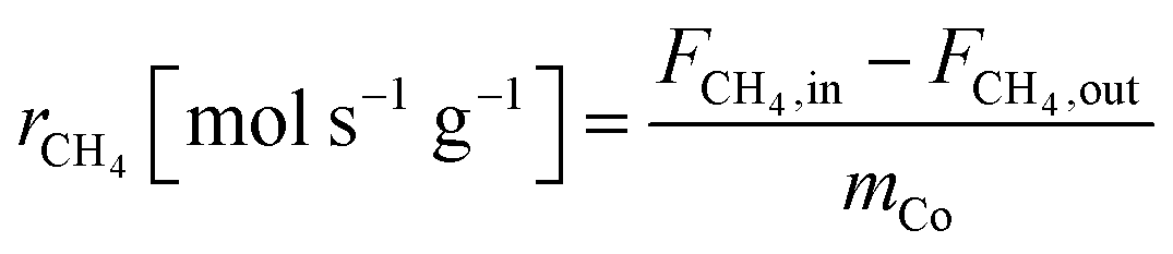
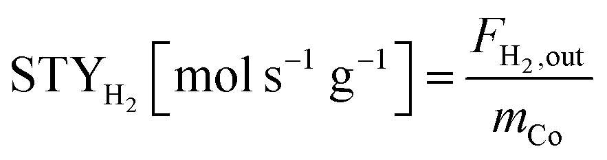
The equations for calculations of process parameters, where transformation rates per mass of cobalt is r, CH4 and CO2 conversion is X, the space-time yield of hydrogen and carbon monoxide is STY and (H2/CO ratio), are given in eqn (6)–(12).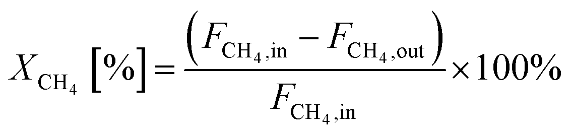 | (6) |
 | (7) |
 | (8) |
 | (9) |
 | (10) |
 | (11) |
 | (12) |
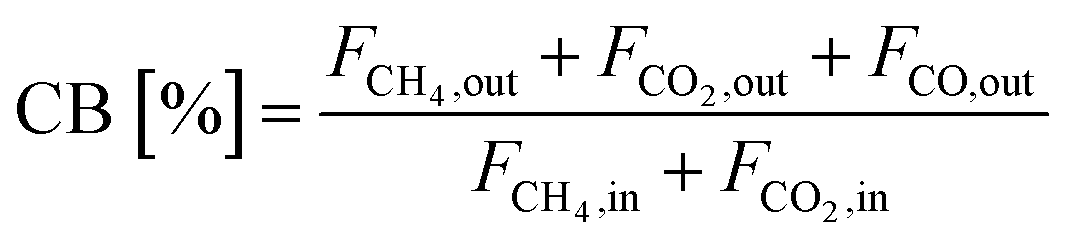
Eqn (13) demonstrates how the carbon balance (CB) was calculated:41
 | (13) |
The initial TOF was calculated as moles of methane converted per moles of exposed cobalt per time (Eqn (14)):
 | (14) |
3. Results and discussion
3.1. Temperature-time profile of the catalyst combustion
Fig. 1 shows the temperature-time profile of the volumetric combustion mode of the 20Co–2Al–10La system. During synthesis, the solution evaporates at ca. 105 °C. According to a previous study,42 the gel is formed from ca. 167 °C, and explosion of the volumetric regime occurs at 270 °C, which is in line with the present work. It is clearly seen that maximal temperatures are as follows: ca. 861 °C in the top layer, ca. 767 °C in the middle layer and 574 °C in the lower layer. Therefore, the combustion temperature is rather high compared to the furnace temperature. It was reported that the CoAl2O4 phase was formed at ca. 650 °C, which is similar to the combustion temperature measured in the present work.43 This phase allows the high catalytic performance of catalysts for DRM.44 Therefore, SCS is the faster and easier way to obtain the high-temperature phase.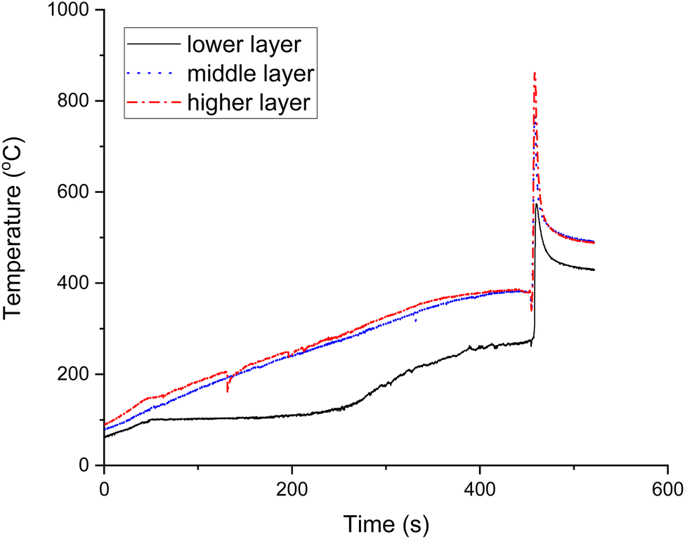 | ||
| Fig. 1 Temperature-time profile of the volumetric combustion mode of the Co–Ce–La–Al catalyst. | ||
3.2. Catalyst characterization results
The XRD results of all fresh (after preparation) and spent (after temperature-cycling experiments) catalysts are shown in Fig. 2. The fresh CoAl (Fig. 2a) exhibited the CoAl2O4 spinel [PDF 01-082-2252] as the main phase, while weak peaks that match metallic cobalt [PDF 01-071-4651] are also identified. It is also worth mentioning that CoAl2O4 and Co3O4 are isomorphous. This is an important point, which means that the presence of Co3O4 is possible in the catalysts and thus share almost exactly the same unit cell parameters and, therefore, the diffraction peaks in the fresh CoAl sample also fit the Co3O4 phase. The relative peak intensities, however, provide a better match with the CoAl2O4 phase pointing out that, indeed, CoAl2O4 is formed in the catalyst preparation. After using the catalyst in the reaction, the diffraction peaks associated with metallic cobalt increased significantly in intensity indicating that cobalt was reduced during the reaction. In addition, the main phase, CoAl2O4, is no longer detected in the spent catalyst due to the reduction of cobalt. Furthermore, an aluminium-rich mixed-oxide Al2.5Co0.25O4 phase [PDF 04-024-6756] was observed in the spent catalyst, which can alternatively be interpreted as η-Al2.667O4 [PDF 04-(007-2615)] with a similar cubic unit cell. The hexagonal graphite phase [PDF 01-090-1815] was also present in significant amounts in the spent catalysts, which was also observed in a previous study.24 According to the results obtained using the Scherrer formula, the crystallite size of the metallic cobalt phase is rather similar in both fresh and spent catalysts (Table 2). However, the crystallite size calculation of the fresh sample was carried out using only one weak deconvoluted peak, and therefore, cannot be considered very reliable. | ||
| Fig. 2 XRD patterns of the fresh and spent catalysts. (a) CoAl, (b) CoCeAl, (c) CoLaAl, and (d) CoCeLaAl. Notation of peaks according to the assigned phases: (1) cobalt, (2) CoAl2O4/Co3O4, (3) graphite, (4) Al2.5Co0.25O4 (or η-Al2.667O4), (5) CeAlO3, (6) CeO2, (7) polyacetylene, (8) LaCoxAl1−xO3, (9) CoO, and (10) Ce0.5La0.5AlO3. | ||
For the fresh CoCeAl catalyst (Fig. 2b), in addition to metallic cobalt and CoAl2O4, AlCeO3 [PDF 01-081-1185] and CeO2 [PDF 01-081-9112] were detected. Analogously to the current work, CeAlO3 and CeO2 formation was observed in the solution combustion of metal nitrates in the presence of urea or glycine as a fuel.45 CeO2 and CeAlO3 were in the cubic and tetragonal phases.45 Analogously to the spent CoAl catalyst, metallic cobalt was present after the catalytic reaction while its crystallite size did not significantly change during the reaction. A potential partial reduction of cerium can occur during the reaction, i.e. transformation of CeO2 to CeO1.71 [PDF 04-008-6647], which is supported by the literature study46 stating that reduction of CeO2 at 862 °C generated CeO1.82–CeO1.72. The unit cell parameters of CeO2 and CeO1.71 are, however, too similar and peak intensity too low for a definitive conclusion. The presence of reduced CeO1.71 in the spent CoCeAl catalyst can indicate a high coking degree of this spent catalyst (see Section 3.1.7), because it was stated in a previous study47 that CeO2 plays an important role in preventing the oxidation of Co species via an electronic interaction. Furthermore, CeO2 inhibits catalyst deactivation, when CO gasification can occur. In addition to graphite being present in the spent CoCeAl catalyst, the small peak at 25.38° (2θ) may indicate the formation of trans-polyacetylene [PDF 00-047-2029], while the graphite main peak is at 26.08°.
For the fresh CoLaAl (Fig. 2c) catalyst, similarly to the other prepared catalysts, CoAl2O4 and metallic Co were identified. The generation of metallic cobalt can be explained by the reduction of cobalt from a higher oxidation state by NH3 and CO released during solution combustion synthesis using urea as a fuel.48 In addition, peaks corresponding to a mixed-oxide LaCo0.7Al0.3O3 phase [PDF 04-023-7810] and CoO [PDF 04-006-1772] were also found, but it is worth mentioning that the former is isomorphous with LaAlO3 [PDF 04-007-4276] and with different compositions of LaCoxAl1−xO3, and thus, the PXRD results are inconclusive on whether this phase indeed contains cobalt. Similar to the current results, it was reported in a previous study49 that the LaCo0.7Al0.3O3 phase was formed when the catalyst was prepared by a sol–gel method in the presence of citric acid and finally calcined at 750 °C for 6 h. Based on the Scherrer equation, the smallest cobalt crystallite size was observed in the fresh CoLaAl catalyst. In the spent catalyst, the mixed oxides as well as CoO were decomposed due to the reduction of the cobalt during the reaction. The crystalline phases found in the spent CoLaAl were Co and LaAlO3 [PDF 04-007-8842], which were formed during the reaction, while no graphite was observed in the diffractogram. It is also important to note that neither graphite nor other forms of carbon could be observed in the spent CoLaAl catalyst. It was also confirmed by Raman spectroscopy in a previous study50 that lanthanide doping on Al2O3 reduced the crystallinity of carbon deposits and inhibited carbon deposition on the catalyst surface during DRM. The XRD pattern of the catalyst tested for 20 h TOS stability is presented in Fig. S1 (ESI†).
For fresh CoCeLaAl (Fig. 2d), the LnAlO3 phase (where Ln can be La and/or Ce) was identified, which was assigned as Ce0.5La0.5AlO3 [04-014-7057] based on the reaction stoichiometry, although the SEM-EDX results indicated a slightly larger relative proportion of Ce than that of La. In the fresh tetrametallic catalyst, the spinel CoAl2O4 phase is also observed together with metallic cobalt. The peaks corresponding to the Ce0.5La0.5AlO3 phase do not show changes during the catalytic reactions, while the CoAl2O4 phase is no longer observed in the spent catalyst. Instead, the metallic Co peaks increase in intensity, while the peaks corresponding to a hexagonal graphite phase also emerge.
Transmission electron micrographs of the spent catalysts are demonstrated in Fig. 3. The mean metal particle size ranged from 19 nm to 28 nm (Table 2 and Fig. 3). Based on TEM analysis, the CoCeLaAl catalyst has the largest average metal particle size. As can be seen from Fig. 3, Co particles are located at the tip of carbon nanotubes in more active CoLaAl and CoCeLaAl catalysts and the catalyst is still active, when metal particles are located at the tip of carbon filaments, as also demonstrated in a previous study.50–53 In addition, according to the XRD analysis, CoAl, CoCeAl and CoCeLaAl contain graphitic carbon, while CoLaAl did not contain peaks for carbon (see Section 3.1.1). The diameter of carbon nanotubes is also important for a deep understanding of carbon deposition in the catalyst. In the present investigation, the average diameter of the carbon nanotubes in each catalyst is as follows: CoAl 35 nm, CoCeLaAl 34 nm, CoCeAl 32 nm, and CoLaAl 30 nm. It is interesting that metal particles in CoAl are smaller than those in CoCeLaAl; however, the diameter of carbon nanotube is larger in the former one. As a comparison, for the spent Co–Al catalysts prepared by conventional impregnation, carbon nanotubes in the range of 14–66 nm were observed, while in the catalysts synthesized by sol–gel, the diameter of nanotubes is in the narrower range (ca. 14–28 nm).54 In addition, for CoLa/Al2O3, carbon nanotubes with a diameter of ca. 22 nm were detected, when this catalyst was used in DRM in the temperature range of 650–750 °C.50
 | ||
| Fig. 3 TEM images of the spent (a) CoAl, (c) CoCeAl, (e) CoLaAl, and (g) CoCeLaAl catalysts. (b), (d), (f) and (h) Corresponding metal particle size distributions. Scale bar = 100 nm. | ||
The SEM-EDX results show that the catalyst particles were of irregular shapes up to 130–140 μm (Fig. S2 and Table 3, ESI†). On all catalysts, surface holes are visible, which create mesopores. The cobalt loading is high in CoAl, while for tri- and tetrametallic catalysts it was in the range of 35–38 wt%.
| Catalyst | Cobalt (wt%) | Oxygen (wt%) | Aluminium (wt%) | Cerium (wt%) | Lanthanum (wt%) |
|---|---|---|---|---|---|
| CoAl | 51.32 ± 0.57 | 28.74 ± 0.29 | 19.94 ± 0.15 | 0 | 0 |
| CoCeAl | 35.91 ± 0.57 | 24.99 ± 0.43 | 11.24 ± 0.15 | 26.73 ± 0.52 | 0 |
| CoLaAl | 35.56 ± 0.59 | 24.04 ± 0.42 | 12.54 ± 0.15 | 0 | 23.24 ± 0.44 |
| CoCeLaAl | 38.48 ± 0.59 | 24.03 ± 0.45 | 11.72 ± 0.15 | 14.25 ± 0.86 | 10.57 ± 0.64 |
The specific surface area of the catalysts was ca. 9–13 m2 gcat−1 (Table 4), and as an example two adsorption–desorption isotherms are shown in Fig. S3 (ESI†). All the studied catalysts exhibited some mesoporosity. The pore sizes varied from 3.5 to 3.7 nm being mesopores. No micropores were present in these catalysts. For catalysts prepared by SCS, low values of surface area are typical.55
Hydrogen TPR results show that the highest hydrogen consumption was observed for CoCeLaAl followed by CoLaAl, while the third lowest hydrogen consumption was recorded for CoCeAl. As expected the lowest hydrogen consumption is found for CoAl due to strong interactions of Co with the support.56 This result cannot be directly correlated with the metal particle size of the spent catalyst.
Hydrogen consumption was related to the relative peak area obtained from hydrogen TPR when using the same catalyst mass. The results indicated that for the fresh catalysts, the relative peak area increased as follows: CoAl < CoCeAl < CoLaAl < CoCeLaAl (Table 5). Hydrogen TPR results show that for CoCeLaAl, reduction started already at 150 °C (Fig. 4), while the first maximum temperature for hydrogen consumption close to 360 °C was observed for CoCeLaAl, CoLaAl and CoAl. CoAl catalysts with the highest Co content among the studied catalysts (Table 3) exhibited the lowest hydrogen consumption. This indicates that Co has strong interactions with Al species, which makes its reduction difficult. For CoAl, hydrogen consumption increased above 700 °C. Noteworthy is that high hydrogen consumption is only observed for CoAl catalysts at high temperatures, but not for lanthanide-modified CoAl catalysts (Fig. 4).
| Catalyst | T 1,max (°C) | T 2,max (°C) | T 3,max (°C) | Normalized peak area |
|---|---|---|---|---|
| CoAl | 358 | 417 | 571 | 0.69 |
| CoCeAl | 459 | 528 | 599 | 0.79 |
| CoLaAl | 366 | 421 | 518, 587 | 0.89 |
| CoCeLaAl | 361 | 421 | 599 | 1.0 |
 | ||
| Fig. 4 Hydrogen TPR of all catalysts. | ||
The second lowest hydrogen consumption was recorded for CoCeAl. At a lower temperature range, the hydrogen consumption for this catalyst is rather low (Fig. 4) because based on XRD, it contained mainly CeAlO3 (Fig. 2) and CoAl2O4/Co3O4 phases. It should, however, be noted that these phases have the same unit cell parameter. As a comparison, the reduction of pure Co3O4 is occurring in two steps, i.e. CoO is formed from Co3O4 in the first step in the temperature range of 290–320 °C and CoO is then reduced to metallic cobalt in the second step in the temperature range of 450–490 °C,37,57 while CeO2 TPR has two peaks at 507 °C and 877 °C corresponding to the surface and bulk reduction of CeO2, respectively.58 In another work59 surface, subsurface and bulk CeO2 were reduced at 390, 507 and 810 °C, respectively. However, in Fig. 4, no peak at 507 °C was visible for CoCeAl, while a peak maximum was observed at 518 °C. According to XRD (Fig. 2), the main phase is CeAlO3 in this catalyst and only traces of CeO2 were observed. It was also stated that above 500 °C, hydrogen consumption is related to interactions between Co and Ce species60 as is the case also in the current work. Analogously as reported in a previous study60 for Ce–Co2AlO4, hydrogen consumption was shifted to a lower temperature. It can thus be speculated that the hydrogen consumption above 500 °C might be related to reduction of CeO2. A peak at 602 °C in hydrogen TPR was observed in a previous study61 for CeO2–AlO3 calcined at 900 °C which is also in line with the current data. Thus, it can be speculated that in the current study, the hydrogen consumption is related to the reduction of cobalt, while for Ce-loaded catalysts, surface CeO2 reduction is occurring above 500 °C and the already formed CeAlO3 phase is reduced at higher temperatures. Note that metallic Ce cannot be obtained from CeO2 by reduction under hydrogen at 800 °C. A rather low hydrogen consumption for CoCeAl can also be related to its relatively lower Co content in comparison to La-modified catalysts (see below).
Both La-modified catalysts in the current work exhibited high relative hydrogen consumption (Table 5). In the current case, CoLaAl contained a mixed LaCoxAl1−xO3 phase (Fig. 2), which was formed in high-temperature calcination analogously as reported in a previous study.49 This mixed oxide, LaAl0.25Co0.75O3, exhibited a hydrogen consumption peak between 300 and 600 °C.49 In the current case, the hydrogen consumption for CoLaAl, based on XRD LaCo0.7Al0.3O3, was analogously observed between 300 and 670 °C, and high hydrogen consumption was visible already between 320 and 370 °C related to cobalt species. In addition, the mixed oxide LaCoxAl1−xO3 was present in the fresh and spent catalyst and Co as confirmed in XRD. Furthermore, it was stated that Co3+ could be reduced at a lower temperature without any clear formation of an intermediate Co2+.49 Opposite to the results of ref. 49, Co2+ formation and reduction to metallic Co could be seen above 500 °C in the current work. It can be seen that in the current work, high hydrogen consumption for CoLaAl and CoCeLaAl with high Co/(La + Ce) atomic ratios of 3.6 and 3.7, respectively, was detected, while this ratio was only 3.2 for the CoCeAl catalyst exhibiting a much lower hydrogen consumption.
The XPS results are shown in Table 6 and Fig. 5. XPS results for all the fresh and spent catalysts exhibit a peak close to 780 eV, which denote the presence of Co oxides,62 while the metallic cobalt should be found at 778.2 eV. Furthermore, the presence of a peak at 785.5 eV is a satellite peak of CoO, showing clearly its presence in all samples.61
| Catalyst | Co 2p (eV) | Al 2p (eV) | Ce 3d (eV) | La 3d (eV) | O 1s (eV) |
|---|---|---|---|---|---|
| CoAl | 780.4 (780.8) | 73.8 (74.6) | n.a. | n.a. | 529.7 (533.2) |
| 785.5 (785.7) | 531.1 (531.6) | ||||
| 532.6 (530.4) | |||||
| CoCeAl | 780.1 (781.6) | 70.7 | 73.6 (74.1) | n.a. | 529.6 (530.1) |
| 784.8 (787.1) | 882.4 (882.2) | 529.6 (531.7) | |||
| 885.9 (885.9) | 531.1 (533.1) | ||||
| 898.1 (898.6) | |||||
| CeLaAl | 780.4 (781.6) | 70.4 | n.a | 834.2 (835.1) | 529.7 (530.2) |
| 786.2 (787.1) | 73.5 (74.3) | 838.0 (838.9) | 531.3 (532.0) | ||
| 532.8 (533.6) | |||||
| CoCeLaAl | 780.2 (787.4) | 70.8 (74.1) | 882.1 (881.9) | 834.0 (834.7) | 529.8 (530.0) |
| 785.5 (781.3) | 73.5 | 885.7 (885.9) | 838.3 (838.5) | 531.3 (531.7) | |
| 889.5 | 532.5 (533.1) | ||||
| 898.2 |
 | ||
| Fig. 5 XPS results of the (a) fresh Co 2p, (b) spent Co 2p, (c) La 3d, (d) Ce 3d, (e) Al 2p fresh, (f) Al 2p spent, (g) O 1s fresh, (h) O 1s spent, (i) C 1s fresh and (j) C 1s spent catalysts. | ||
In the XPS spectra of fresh CoCeAl, the Ce 3d peak at 917 eV confirms the presence of CeO2 in the fresh CoCeAl and the peaks at 882.35 eV, 888.75 eV, 898.14 eV and 908 eV indicate the presence of Ce4+ as also reported.47 Although peaks related to Ce3+ are found at 885.43 eV, no peak is found at 880 eV for Ce3+ in any samples.47,62 Thus, it can be concluded that the presence of Ce3+ in the fresh CoCeAl cannot be excluded, because the peak close to 885 eV related to Ce3+ was present. The presence of Ce3+ indicates strong interactions between metals and oxygen defects on the catalyst surface, which can facilitate CO2 adsorption, dissociation and carbon elimination.47 It should also be noted that in XRD CeAlO3 with Ce3+ was observed. For the spent CoCeAl catalyst, slightly higher peak positions in comparison to the corresponding fresh catalyst were found, indicating partial oxidation of the species. In addition, no metallic cobalt was visible on the catalyst surface of the fresh or spent CoCeAl catalysts by XPS, while in XRD measurements, Co0 was observed. It should, however, be pointed out that metallic cobalt can be easily oxidized, and moreover, the XRD pattern reflects the bulk composition.
The O 1s peaks especially for CoCeAl at 529.6 eV and 531.1 eV could be denoted as lattice oxygen in CeO2 and adsorbed oxygen species close to 531 ± 0.5 eV, respectively.50,63,64 The role of adsorbed oxygen or oxygen in surface hydroxyl is important in catalysis, because adsorbed oxygen species have high reactivity and they can participate in oxidation reactions and oxygen vacancies can be created. Oxygen vacancies can promote CO2 activation in lanthanide-doped catalysts and promote gasification of carbon deposits in the spent catalyst.
In both fresh and spent CoLaAl samples, peaks for La 3d5/2 and La 3d3/2 in the range of 832.2–842.6 eV and 849.0–860.1 eV were observed corresponding to the presence of La2O3 on the surface.47 La 3d5/2 and La 3d3/2 have peaks close to 834 eV and 851 eV, while the corresponding satellite peaks are found close to 838 eV and 855 eV.65 Furthermore, the XRD pattern of the fresh CoLaAl contained a mixed LaCoAl oxide, which was also present in the spent catalyst. However, the difference can be related to surface vs bulk analysis when using XPS and XRD, respectively. The binding energies for La 3d in the spent CoLaAl catalyst increased, indicating surface oxidation of La, while in the XRD pattern, only the LaCoxAl1−xO3 phase was observed both in fresh and spent catalysts.
Analogously to CoLaAl, nearly identical La 3d peaks were found in CoCeLaAl and the binding energies for La 3d in the spent CoCeLaAl catalysts also increased, while XRD results of the fresh and spent catalysts showed the presence of stable perovskite Ce0.5La0.5AlO3 (Fig. 2).
The carbon peak for the spent CoLaAl catalyst was at 284.5 eV, while that for the other three spent catalysts was close to 284.6 eV. According to a previous study,62 C–C and C![[double bond, length as m-dash]](https://www.rsc.org/images/entities/char_e001.gif) C carbon have peaks at 284.8 eV and 284.5 eV, respectively. This result indicates that the coke in the spent CoLaAl was more unsaturated.
C carbon have peaks at 284.8 eV and 284.5 eV, respectively. This result indicates that the coke in the spent CoLaAl was more unsaturated.
From the O 1s peaks of the spent catalysts, typically peaks are found in the range of 531.2–533.6 eV with the corresponding C 1s peak in the range of 284.5–284.6 eV. These can be assigned as organic CO or C–O species on the spent catalysts, because the corresponding peaks are found in the range of 531.5–532 eV and 533 eV, respectively with the corresponding C 1s peak at 284.8 eV.62
The TPO results of the spent catalysts show that the CoCeLaAl catalyst exhibited the highest TC signal and the highest relative amount of CO2 formed during TPO (Fig. 6 and Table 7). The second highest peak area was recorded for CoLaAl. The third highest amount of carbon was observed for CoCeAl and the lowest amount was seen for CoLaAl. These results are in line with the CHNS results. Graphite was identified in XRD patterns in CoCeLa/MA,47 while in the current research, graphite was found in all spent catalysts except CoLaAl. As the mean size of the Co crystallites is rather similar, the influence of the metal particles on the coke formation cannot be unequivocally established.
 | ||
| Fig. 6 (a) TCD signal, (b) formed CO and (c) CO2 during temperature-programmed oxidation of spent catalysts. | ||
| Catalyst | T 1,max (°C) | T 2,max (°C) | T 3,max (°C) | T 4,max (°C) | Relative peak area of CO2 based on MS | Carbon determined by CHNS (wt%)/exposeda gcat. | H/C molar ratio determined by CHNS |
|---|---|---|---|---|---|---|---|
| a For CoAl catalyst the carbon determined by CHNS (wt%) per exposed gcat. is 53.2 wt% gexposed cat−1. | |||||||
| CoCeLaAl | 245 | 452 | 484 | n.a. | 1.0 | 42.2 | 0.07 |
| CoCeAl | 253 | 465 | 525 | n.a. | 0.73 | 30.7 | 0.11 |
| CoLaAl | 225 | 330 | 481 | 605 | 0.18 | 10.0 | 0.08 |
The peaks detected below 500 °C correspond to amorphous carbon, while the one close to 600 °C originated from graphitic carbon.66 The TC signal of CoLaAl, therefore, supports the findings from the PXRD pattern of the spent CoLaAl catalyst, where no crystalline graphite was detected. The negative TC signal close to 600 °C corresponds to a high amount of heat formed during burning graphitic coke. The molar ratio of H/C was very small for the three catalysts, indicating that these spent catalysts also contained graphitic coke. The molar H/C ratio of 2 and 1 in carbonaceous species is related to paraffinic and aromatic hydrocarbons.67 The high carbon content in CoCeAl is related to the absence of CeO2 in the spent CoCeAl catalyst (see Section 3.1.1), indicating that it is not active for the gasification of carbonaceous species.47
3.3. Catalytic results
The catalytic performance of CoAl, CoCeAl, CoLaAl and CoCeLaAl was carried out in the temperature cycling experiment from 600 to 900 °C and returning to the initial temperature (Fig. 7 and Table 8). The highest methane transformation rate was recorded for CoCeLaAl at 6.0 × 10⁻⁵ mol s−1 g−1 at 600 °C due to its high reducibility (Table 5). Although other catalysts exhibited initially low activity at 600 °C, the values of transformation rates and space-time yields sharply increased at 700 °C (Fig. 7b, d, f and h). | ||
| Fig. 7 Reaction rates for methane and CO2 and carbon balance for (a) CoAl, (c) CoCeAl, (e) CoLaAl, and (g) CoCeLaAl and (b), (d), (f) and (h) the corresponding space time yields and H2/CO ratios for different catalysts. Notation: 1. 600 °C, 2. 700 °C, 3. 800 °C, 4. 900 °C and 5. 600 °C. | ||
| Entry | Catalyst | r CH4,600°C (mol s−1 gCo−1) | r CO2, 600 °C (mol s−1 gCo−1) | TOFCH4,600°C (s−1) | CB600°C (%) | r CH4,800 °C (mol s−1 gCo−1) | r CO2,800 °C (mol s−1 gCo−1) | CB800°C (%) | STYH2,800 °C (mol s−1 gCo−1) | STYCO,800 °C (mol s−1 gCo−1) | H2/CO 600°C | E A (kJ mol−1) |
|---|---|---|---|---|---|---|---|---|---|---|---|---|
| 1 | CoAl | 1.0 × 10⁻⁵ (5.6 × 10⁻⁵) | 3.4 × 10⁻⁵ (6.8 × 10⁻⁵) | 0.01 | 84 (78) | 1.3 × 10⁻⁴ | 1.2 × 10⁻⁴ | 67 | 2.5 × 10⁻⁴ | 1.6 × 10⁻⁴ | 1.8 (1.1) | 39 (600–700 °C) 19 (700–900 °C) |
| 2 | CoCeAl | 6.2 × 10⁻⁶ (3.9 × 10⁻⁵) | 4.4 × 10⁻⁵ (7.1 × 10⁻⁵) | 0.007 | 82 (81) | 1.2 × 10⁻⁴ | 1.2 × 10⁻⁴ | 68 | 1.9 × 10⁻⁴ | 1.6 × 10⁻⁴ | 0.0 (0.9) | 101 (600–700 °C) 30 (700–900 °C) |
| 3 | CoLaAl | 1.9 × 10⁻⁵ (7.2 × 10⁻⁵) | 3.0 × 10⁻⁵ (7.4 × 10⁻⁵) | 0.03 | 85 (82) | 1.6 × 10⁻⁴ | 1.3 × 10⁻⁴ | 70 | 3.1 × 10⁻⁴ | 2.0 × 10⁻⁴ | 0.0 (1.0) | 100 (600–700 °C) 17 (700–900 °C) |
| 4 | CoCeLaAl | 6.0 × 10⁻⁵ (6.0 × 10⁻⁵) | 6.6 × 10⁻⁵ (6.5 × 10⁻⁵) | 0.08 | 84 (80) | 1.3 × 10⁻⁴ | 1.2 × 10⁻⁴ | 68 | 2.7 × 10⁻⁴ | 1.6 × 10⁻⁴ | 1.0 (1.2) | 37 (600–700 °C) 17 (700–900 °C) |
CoLaAl displayed the highest activity at 800 °C among all catalysts studied here. The second highest activity was obtained for CoCeLaAl. Furthermore, the coke amount in CoLaAl was found to be the lowest. When comparing with the literature,68 the catalytic activity of LaCo/MA was higher than that of CeCo/MA (MA denotes mesoporous alumina). Both of these catalysts exhibited a Co3O4 particle size of ca. 13 nm and contained γ-Al2O3, Co3O4 and CoAl2O4 phases. In addition, the surface areas were 164 and 169 m2 g−1 for CeCo/MA and LaCo/MA, respectively.
It is important to note that CH4 and CO2 transformation rate values for tetrametallic catalysts remained stable at the second cycle, while for other catalysts, these values significantly differ compared to initial ones. In all cases, CO2 transformation rates were larger than methane transformation rates; moreover, the H2/CO ratio was close to unity in the second cycle, indicating the occurrence of reverse water–gas shift.47 The carbon balance for catalysts decreased with the increase in temperature; however, it was recovered at the second cycle at 600 °C analogously to a previous study.55
Initial TOF for methane transformation increased in the following order: CoCeLaAl > CoLaAl > CoAl > CoCeAl. The higher initial TOF values for CoCeLaAl and CoLaAl can be related to the high relative hydrogen consumption in TPR (Table 5). The calculated initial TOF values were rather small in comparison to a previous study,57 in which TOF for Co–Al–La catalysts prepared by a flame spray pyrolysis technique at 700 °C was ca. 14 s−1; however, the specific surface areas of these catalysts were also much larger being in the range of 111–122 m2 g−1.
Apparent activation energy for methane transformation was calculated from the Arrhenius equation to evaluate the catalyst activity. The results indicated that the activation energy of CoCeAl and CoLaAl is ca. 100 kJ mol−1 in the temperature range of 600–700 °C (Table 8), which is close to that of CoCe/Al reported in previous studies.52,53 The activation energy decreased, however, at elevated temperatures. The lowest activation energy at 700–900 °C was observed for the highly active CoLaAl and CoCeLaAl catalysts. At 600–700 °C, apparent activation energy was 39 and 37 kJ mol−1 close to the results reported previously.55,69–71
Space-time yield (STYH2) for hydrogen was the highest for CoLaAl at 800 °C, while the lowest one was obtained for CoCeAl (Table 8), even lower than that for CoAl. The CoCeAl catalyst exhibited the third lowest hydrogen consumption (Table 5), which is explaining its low activity. The STY of hydrogen increased as follows for lanthanide-modified catalysts: CoLaAl < CoCeLaAl< CoAl < CoCeAl, the highest coke formation was observed for CoAl still being the third most active in the production of hydrogen (Fig. 8). As a comparison with the previous results,68 the STY for hydrogen for CeCo/MA and LaCo/MA was 0.97 mmol gCo−1 s−1 and 1.0 mmol gCo−1 s−1, respectively, while in the current case, the corresponding values for CoCeAl and CoLaAl are 0.19 mmol gCo−1 s−1 and 0.31 mmol gCo−1 s−1, respectively. Such values are in line with lower specific surface areas of CoLaAl and CoCeAl in the current work, especially considering that hydrogen production is promoted not only by metallic sites, but also in the interfacial regions between the metal and the support.52,53 It was confirmed that in the current case, the presence of the LnAlO3 phase (Ln is Ce or La) increased hydrogen uptake (Table 5) and catalytic activity (Table 8). Furthermore, both CeAlO3 and LaAlO3 were found in the spent catalyst after temperature cycling and the high stability of LaAlO3 after DRM at 700 °C was also confirmed previously.72 Perovskite-type ABO3 has oxygen vacancies available on the catalyst surface, which weaken the metal–oxygen bond and facilitate easier metal reduction.73 Metallic Co and LaAlO3 determine the activity of the catalyst; however, still few studies used Co-based catalysts containing rare-earth metals. DRM tests for Ni and LaAlO3 have been reported.38 Furthermore, hydrogen yields over Ni/LaAlO3 were much higher than those for Ni/α-Al2O3. This was interpreted due to a higher Ni dispersion in the latter catalyst.38
 | ||
| Fig. 8 Space-time yield (STY) of hydrogen at 800 °C as a function of the carbon amount determined via CHNS. Amount of coke was given per exposed amount of the catalyst because the amounts of catalysts in experiments were different and 2 mL of a catalyst was used. | ||
The H2/CO ratios at 900 °C in the current work were decreasing as follows: CoCeLaAl > CoAl > CoLaAl > CoCeAl decreasing from 1.63 to 1.25. These values indicate CH4 decomposition, while more enhanced CO2 reactions according to the reverse water gas shift reaction (eqn (5)) consume hydrogen and CO2 and produce CO and water. For example, H2/CO ratios varied in the range of 0.78–0.86 and the lowest H2/CO ratio was obtained with non-promoted cobalt on the mesoporous alumina catalyst.67 Analogously, H2/CO ratios lower than one were reported for CeLa/MA, CoLa–Ce/MA, where MA denotes mesoporous alumina.47 The differences in comparison to the current work might be the smaller metal particle sizes and larger specific surface area; however, these catalysts were extensively deactivated, showing a large decrease in methane conversion with increasing time-on-stream.
In this study, Ce doping of CoAl did not improve the catalytic activity and a relatively large amount of coke was determined in this catalyst (Fig. 9). Furthermore, CoCeLaAl was active for hydrogen production, although this catalyst exhibited the highest amount of coke in the spent catalyst (Fig. 2). Furthermore, according to a previous study,47 the addition of Ce to Co–La/MA catalyst reduced coke accumulation due to the presence of the CeO2 phase, as confirmed by XRD, and improved its performance during DRM. It is known that CeO2 exhibits oxygen mobility facilitating coke gasification. In the current case, for the fresh CoCeLaAl catalyst, no diffraction peak for CeO2 was observed in the fresh catalyst (Fig. 2).
 | ||
| Fig. 9 Reaction rates for methane and CO2 and carbon balance for CoLaAl for (a) 20 h and (c) 50 h TOS. (b) and (d) Corresponding space-time yields and H2/CO ratios for (b) 20 h and (d) 50 h TOS. Conditions: 800 °C, WHSV h−1. | ||
High catalytic activity of CoLaAl can be related to the presence of spinel CoAl2O4, Co3O4, CoO and Co phases in the fresh catalyst (Fig. 2). Especially, CoAl2O4 has been shown to exhibit high activity in DRM at 700 °C, being however, prone to coking.44 Furthermore, CoAl2O4, Co3O4 and CoO were not observed in the spent catalyst, indicating that the formed perovskite-type mixed oxide LaCoxAl1−xO3 was suppressing coking. In comparison with the literature, better coking resistance and catalytic activity have been reported for Ni on lanthanum aluminate perovskites.74,75
For the best catalyst, CoLaAl, a long-term stability test was also performed and the results showed that the transformation rates and space-time yields remained constant throughout 20 h at 800 °C (Fig. 9 and Table 9). The PXRD pattern of 20 h spent sample indicated that the crystalline phases are LaAlO3 [PDF 04-006-0695] and graphite [PDF 00-023-0064]. However, the signal-to-noise ratio of this data is rather weak, which makes the analysis difficult.
| Catalyst | r CH4C (mol s−1 gCo−1) | r CO2 (mol s−1 gCo−1) | TOFCH4 (s−1) | CB (%) | STYH2 (mol s−1 gCo−1) | STYCO (mol s−1 gCo−1) | H2/CO |
|---|---|---|---|---|---|---|---|
| CoLaAl | 1.4 × 10⁻⁴ (1.4 × 10⁻⁴) | 1.0 × 10⁻⁴ (1.1 × 10⁻⁴) | 0.2 | 83 (82) | 2.0 × 10⁻⁴ (2.7 × 10⁻⁴) | 1.9 × 10⁻⁴ (1.9 × 10⁻⁴) | 1.1 (1.4) |
The CO2 transformation rate was lower than the CH4 transformation rate. As a comparison to a previous study,47 it was interesting to note that the CoLa/MA catalyst was not stable in DRM at 750 °C and methane and CO2 conversion in 20 h TOS decreased 27% and 14%, respectively, while in the current case no deactivation was observed (Table 10). The Co/La weight ratio was 2, while in the current case it was only 1.5.47 Furthermore, the Co3O4 crystal size was 11.5 nm, while in this work it was ca. 21–24 nm (Table 2). CoLaAl contained also CoAl2O4 and mixed La–Co–Al oxide phases, which were not present in Co La-Ce/MA catalyst.47 It could be stated that close interactions between different metals is important for a stable catalyst performance in the CoLaAl catalyst.
| Catalyst | Conditions | X CH4 (%) | X CO2 (%) | H2/CO | Particle size (nm) | D deac.a (% min−1) | Ref. |
|---|---|---|---|---|---|---|---|
a Deactivation rate is calculated from methane conversion as follows:  .
b Data from Table 2. .
b Data from Table 2.
|
|||||||
| CoLaAl |
T = 800 °C, CH4/CO2 = 1:1, 3000 h−1, 20 h TOS, 0.62 g cat. |
89 (91) | 84 (86) | 1.1 (1.4) | 21–24b | 0 | This work |
| CoLa/MA |
T = 750 °C, CH4/CO2 = 1:1, 60000 mL h−1 g−1, 20 h TOS, 0.1 g cat. |
90 (67) | 90 (80) | 0.85 (0.85) | n.a. | 2.1 × 10⁻⁴ | 47 |
| 3Co–1Ce/Ac–N |
T = 800 °C, CH4/CO2 = 1:1, 120 mL g−1 min−1, 10 g cat. |
83 (62) | 95 (75) | n.a. | 8–12 | 3.4 × 10⁻⁴ | 76 |
| CoAl/CeO2 |
T = 850 °C, CH4/CO2/N2 = 40/40/20, (15661 N cm3 h−1 gcat−1), 10 g cat., 20 h TOS, 0.05 g cat. |
56 (49) | 74 (68) | 0.77 (0.73) | n.a. | 1.0 × 10⁻⁴ | 52 |
| 5Co–2La/ZrO2 |
T = 750 °C, CH4/CO2 = 1:1, 60000 mL h−1 g−1 |
26 (27) | 43 (44) | 0.77 (0.76) | n.a. | 0 | 77 |
According to CHNS analysis, the spent CoLaAl catalyst possessed the lowest carbon formation in the temperature cycling experiment. TPO results also revealed that the type of carbon was amorphous, e.g. more active, burnt at 481 °C. Due to oxygen mobility of La-doped Co-based catalysts, carbon accumulated during methane decomposition on the active sites is readily oxidized, which can be a reason for the low rate of coke formation.47 In this regard, La-modified catalysts can be stable for a long period in DRM.
The H2/CO ratio was unstable for the CoLaAl catalyst; however, it was close to unity in the first 5 h, increasing thereafter to 1.7 and decreasing to 1.4 finally at 3 h of time-on-stream. This might be affected by cooling the reaction after the first day (7 h time-on-stream) and continuing thereafter at the same temperature on the second and third days, respectively. Furthermore, XRD measurements of the spent CoLaAl catalysts revealed that although some metallic cobalt was present in the sample, the crystallinity of the catalyst substantially decreased (Fig. S1, ESI†) opposite to the same catalyst subjected to the temperature cycling test. The H2/CO ratio was stable during 20 h time-on-stream being 0.85.47
Table 10 shows the comparison of the current results with those reported in the literature.47,52,76,77 According to a previous study,75 deactivation by methane is not identified; moreover, the coke content was 0.2 wt% after 6 h of reaction. However, the catalytic activity is very low in comparison with the CoLaAl catalyst used in the current study. The metal particle size in 3Co–1Ce/Ac–N is smaller than that of CoLaAl, but conversion is lower.76
Thus, the catalyst of the current study demonstrated high and stable catalytic performance compared to the catalysts reported previously.53,76,77 Although CoLa/MA is more active than CoLaAl, the conversion values decreased with time-on-stream.
4. Conclusions
In this work, Co–Al-based Ce- and La-containing catalysts were prepared by a solution combustion method. The surface area of catalysts obtained by SCS was in the range of 9–13 m2 g−1, with the catalysts containing mesopores. The XPS findings demonstrated the presence of cobalt oxides in the fresh catalysts. The catalysts, according to XRD, contained, CoAl2O4 spinel, which, however, decomposed during the reaction, forming metallic cobalt. In addition, the fresh catalysts contained both metallic cobalt and CoO. The metal particle sizes for the spent catalysts varied in the range of 19–25 nm and both CoCeAl and CoLaAl catalysts exhibited the smallest metal particles based on the TEM results.The DRM reaction was studied in the temperature range of 600–900 °C over Co–Al and its Ce- and La-modified counterparts. According to the results obtained from temperature cycling experiments, Ce doping did not enhance the activity of CoAl; however, partial substitution by La could significantly increase it. CoLaAl catalysts contained a perovskite-type mixed oxide LaCoxAl1−xO3 being isomorphous with LaAlO3 and no carbon species were found in the spent catalyst determined by XRD. Furthermore, the spent CoAl, CoCeAl and CoCeLaAl catalysts contained graphite type of carbon. Furthermore, the spent CoLaAl catalyst exhibited the lowest coke formation among all studied catalysts according to the CHNS and TPO results. The catalyst activity was retained due the presence of Co particles on the tip of carbon nanotubes. The second highest active was observed for CoCeLaAl, which also exhibited high hydrogen consumption in temperature-programmed reduction. It can be speculated that the large metal particles, 28 nm, in CoCeLaAl caused the growth of carbon filaments. In this spent catalyst, the second largest amount of coke was observed after Co–Al.
The long-term stability test was conducted over the best CoLaAl catalyst for both 20 h and 50 h time-on-stream. It was shown that the rate of reacting gas transformations both for CH4 and CO were stable during DRM. However, the H2/CO ratio fluctuated in 1.1 and 1.7. The mixed oxide LaCoxAl1−xO3 observed in both fresh and spent catalysts after the temperature cycling text was not however stable after more than 20 h TOS.
Author contributions
Dinmukhamed Shoganbek, investigation. Mark Martinez-Klimov, investigation. Olha Yevdokimova, investigation. Anssi Peuronen, investigation. Mika Lastusaari, investigation. Atte Aho, investigation. Svetlana A. Tungatarova, project administration, supervision, writing review and editing. Tolkyn S. Baizhumanova, investigation. Daulet A. Zhumadullaev, investigation. Manapkhan Zhumabek, investigation. Yermek A. Aubakirov, project administration. Alua Manabayeva, investigation. Päivi Mäki-Arvela, investigation, methodology, supervision, writing original draft. Dmitry Yu. Murzin, methodology, supervision, writing review and editing.Data availability
Some experimental data are available in ESI.† Other data will be made available upon request.Conflicts of interest
There are no conflicts to declare.Acknowledgements
Electron microscopy samples were processed and analyzed at the Electron Microscopy Laboratory, Institute of Biomedicine, University of Turku, which receives financial support from Biocenter Finland. This study has been funded by the Science Committee of the Ministry of Education and Science of the Republic of Kazakhstan (Grant No. BR24992995).Notes and references
- M. Mosinska, M. I. Szynkowska and P. Mierczynski, Catalysts, 2020, 10, 896–923, DOI:10.3390/catal10080896.
- F. Cheng, X. Duan and K. Xie, Angew. Chem., Int. Ed., 2021, 133, 18940–18947, DOI:10.1002/ange.202106243.
- C. C. Chong, Y. W. Cheng, S. N. Bukhari, H. D. Setiabudi and A. A. Jalil, Catal. Today, 2021, 375, 245–257, DOI:10.1016/j.cattod.2020.06.073.
- M. A. Goula, N. D. Charisiou, G. Siakavelas, L. Tzounis, I. Tsiaoussis, P. Panagiotopoulou, G. Goula and I. V. Yentekakis, Int. J. Hydrogen Energy, 2017, 42, 13724–13740, DOI:10.1016/j.jngse.2016.02.021.
- B. C. Ekeoma, M. Yusuf, K. Johari and B. Abdullah, Int. J. Hydrogen Energy, 2022, 47, 41596–41620, DOI:10.1016/j.ijhydene.2022.05.297.
- P. G. Lustemberg, Z. Mao, A. Salcedo, B. Irigoyen, M. V. Ganduglia-Pirovano and C. T. Campbell, ACS Catal., 2021, 11(16), 10604–10613 CrossRef CAS PubMed.
- D. He, J. Yan, K. Chen, L. Zhang, J. Lu, J. Liu and Y. Luo, ACS Catal., 2023, 13, 12114–12124, DOI:10.1021/acscatal.3c00752.
- Q. Wei, X. Gao, L. Wang and Q. Ma, Fuel, 2020, 271, 117631, DOI:10.1016/j.fuel.2020.117631.
- Y. Zhu, W. Ding and Z. Yao, Catal. Sci. Technol., 2023, 13, 178–186, 10.1039/D2CY01595A.
- G. Zhang, J. Liu, Y. Xu and Y. Sun, Int. J. Hydrogen Energy, 2018, 43, 15030–15054, DOI:10.1016/j.ijhydene.2018.06.091.
- Y. Diao, X. Zhang, Y. Liu, B. Chen, G. Wu and C. Shi, Appl. Catal., B, 2021, 301, 120779, DOI:10.1016/j.apcatb.2021.120779.
- D. Shen, J. Wang, Y. Bai, S. Lyu, Y. Zhang and J. Li, Fuel, 2023, 339, 127409, DOI:10.1016/j.fuel.2023.127409.
- M. C. J. Bradford and M. A. Vannice, Catal. Rev., 1999, 41, 1–42, DOI:10.1081/CR-100101948.
- D. Pakhare and J. Spivey, Chem. Soc. Rev., 2014, 43, 7813–7837, 10.1039/C3CS60395D.
- E. D. German and M. Sheintuch, Surf. Sci., 2017, 656, 126–139, DOI:10.1016/j.susc.2016.03.024.
- F. Wang, L. Xu, J. Yang, J. Zhang, L. Zhang, H. Li, Y. Zhao, H. X. Li, K. Wu, G. Q. Xu and W. Chen, Catal. Today, 2017, 281, 295–303, DOI:10.1016/j.cattod.2016.03.055.
- R. Chai, S. Fan, Z. Zhang, P. Chen, G. Zhao, Y. Liu and Y. Lu, ACS Sustainable Chem. Eng., 2017, 5, 4517–4522, DOI:10.1021/acssuschemeng.7b00717.
- F. Mirzaei, M. Rezaei and F. Meshkan, Chem. Eng. Technol., 2014, 37, 973–978, DOI:10.1002/ceat.201300729.
- N. El Hassan, M. N. Kaydouh, H. Geagea, H. El Zein, K. Jabbour, S. Casale, H. El Zakhem and P. Massiani, Appl. Catal., A, 2016, 520, 114–121, DOI:10.1016/j.apcata.2016.04.014.
- M. Yu, Y.-A. Zhu, Y. Lu, G. Tong, K. Zhu and X. Zhou, Appl. Catal., B, 2015, 165, 43–56, DOI:10.1016/j.apcatb.2014.09.066.
- W. Li, Z. Zhao, F. Ding, X. Guo and G. Wang, ACS Sustainable Chem. Eng., 2015, 3, 3461–3476, DOI:10.1021/acssuschemeng.5b01277.
- I. Luisetto, S. Tuti and E. Bartolomeo, Int. J. Hydrogen Energy, 2012, 37, 15992–15999, DOI:10.1016/j.ijhydene.2012.08.006.
- M. B. Bahari, N. H. H. Phuc, F. Alenazey, K. B. Vu, N. Ainirazali and D.-V. N. Vo, Catal. Today, 2017, 291, 67–75, DOI:10.1016/j.cattod.2017.02.019.
- F. Fayaz, L. G. Bach, M. B. Bahari, T. D. Nguyen and K. B. Vu, Int. J. Energy Res., 2018, 43, 405–416, DOI:10.1002/er.4274.
- S. Zeng, Y. Du, H. Su and Y. Zhang, Catal. Commun., 2011, 13, 6–9, DOI:10.1016/j.catcom.2011.06.009.
- N. T. Tran, Q. Van Le, N. Van Cuong, T. D. Nguyen, N. H. Huy Phuc and P. T. T. Phuong, J. Energy Inst., 2020, 93, 1571–1580, DOI:10.1016/j.joei.2020.01.019.
- K. Han, W. Yu, L. Xu, Z. Deng, H. Yu and F. Wang, Fuel, 2021, 291, 120182, DOI:10.1016/j.fuel.2021.120182.
- M. Li and A. C. van Veen, Appl. Catal., B, 2018, 237, 641–648, DOI:10.1016/j.apcatb.2018.06.032.
- R. Dębek, M. Radlik, M. Motak, M. E. Galvez, W. Turek and P. Da Costa, Catal. Today, 2015, 257, 59–65, DOI:10.1016/j.cattod.2015.03.017.
- M. Abdollahifar, M. Haghighi and M. Sharifi, Energy Convers. Manage., 2015, 103, 1101–1112, DOI:10.1016/j.enconman.2015.04.05.
- J. H. Park, S. Yeo, T. J. Kang, H. R. Shin, I. Heo and T. S. Chang, J. CO2 Util., 2018, 23, 10–19, DOI:10.1016/j.jcou.2017.11.002.
- C. S. Intan, S. Soen, S. Rawiyah Khairunida’, I. Ferry, D. Hary, R. Elvi, N. Norikazu and B. Yogi Wibisono, Chem. Eng. J. Adv., 2024, 20, 100655, DOI:10.1016/j.ceja.2024.100655.
- C. Alvarez-Galvan, H. Falcon, V. Cascos, L. Troncoso, S. Perez-Ferreras, M. Capel-Sanchez, J. M. Campos-Martin, J. A. Alonso and J. L. G. Fierro, Int. J. Hydrogen Energy, 2018, 43, 16834–16845, DOI:10.1016/j.ijhydene.2018.04.025.
- F. Deganello and A. K. Tyagi, Prog. Cryst. Growth Charact. Mater., 2018, 64, 23–61, DOI:10.1016/j.pcrysgrow.2018.03.001.
- A. Varma, A. S. Mukasyan, A. S. Rogachev and K. V. Manukyan, Chem. Rev., 2016, 116, 14493–14586, DOI:10.1021/acs.chemrev.6b00279.
- S. Ali, M. M. Khader, M. J. Almarri and A. G. Abdelmoneim, Catal. Today, 2020, 343, 26–37, DOI:10.1016/j.cattod.2019.04.066.
- J. Horlyck, S. Pokhrel, E. Lovell, N. M. Bedford, L. Mädler, R. Amal and J. Scott, Catal. Sci. Technnol., 2019, 9, 4970–4980, 10.1039/C9CY01293A.
- G. P. Figueredo, R. L. Medeiros, H. P. Macedo, A. A. de Oliveira, R. M. Braga, J. M. Mercury, M. A. F. Melo and D. M. Melo, Int. J. Hydrogen Energy, 2018, 43, 11022–11037, DOI:10.1016/j.ijhydene.2018.04.224.
- T. Degen, M. Sadki, E. Bron, U. König and G. Nénert, Powder Diffr., 2014, 29, 13–18, DOI:10.1017/S0885715614000840.
- S. Gates-Rector and T. Blanton, Powder Diffr., 2019, 34, 352–360, DOI:10.1017/S0885715619000812.
- M. S. Ferrandon, C. Byron, G. Celik, Y. Zhang, C. Ni, J. Sloppy, R. A. McCormick, K. Booksh, A. V. Teplyakov and M. Delferro, Appl. Catal., A, 2022, 629, 118379–118393, DOI:10.1016/j.apcata.2021.118379.
- G. N. Kaumenova, G. Xanthopoulou, Y. K. Sovetbek, T. Baizhumanova, S. Tungatarova and S. Kotov, News of the Nat. Acad. Sci. Repub. Kazakhstan, Ser., Chem. Eng. Technol., 2020, 4, 64–72, DOI:10.32014/2020.2518-1491.66.
- N. Srisawad, W. Chaitree, O. Mekasuwandumrong, P. Praserthdam and J. Panpranot, J. Nanomater., 2012, 1, 108369, DOI:10.1155/2012/108369.
- J. Yu, T. Le, D. Jing, E. Stavitski, N. Hunter, K. Lalit, D. Leshchev, D. E. Resasco, E. H. Sargent, B. Wang and W. Huang, Nat. Commun., 2023, 14, 7514, DOI:10.1038/s41467-023-43277-0.
- S. T. Aruna, N. S. Kini and K. S. Rajam, Mater. Res. Bull., 2009, 44, 728–733, DOI:10.1016/j.materresbull.2008.09.034.
- J. P. Holgado, R. Alvarez and G. Munuera, Appl. Surf. Sci., 2000, 161, 301–315, DOI:10.1016/S0169-4332(99)00577-2.
- T. Li, Z. Liang, J. Liu, Y. Zhang, X. Zhang and G. Zhang, Int. J. Hydrogen Energy, 2024, 61, 611–622, DOI:10.1016/j.ijhydene.2024.02.302.
- A. Khort, K. Podbolotov, R. Serrano-García and Y. Gun’ko, Inorg. Chem., 2018, 57, 1464–1473, DOI:10.1021/acs.inorgchem.7b02848.
- N. Tran, F. Martinovic, M. Ceretti, S. Esposito, B. Bonelli, W. Paulus, F. Di Renzo, F. A. Dearsola, S. Bensaid and R. Pirone, Appl. Catal., A, 2020, 589, 117304, DOI:10.1016/j.apcata.2019.117304.
- Z. Liang, Y. Zhang, G. Zhang, J. Liu, Y. Cai, Y. Wang, Y. Zhao, G. Li and K. Bei, Int. J. Hydrogen Energy, 2023, 48, 18644–18656, DOI:10.1016/j.ijhydene.2023.01.301.
- L. Zhou, L. Li, N. Wei, J. Li and J. M. Basset, ChemCatChem, 2015, 7, 2508–2516, DOI:10.1002/cctc.201500379.
- J. H. Park, S. Yeo and T. S. Chang, J. CO2 Util., 2018, 26, 465–475, DOI:10.1016/j.jcou.2018.06.002.
- J. H. Park, S. Yeo, T. J. Kang, I. Heo, K. Y. Lee and T. S. Chang, Fuel, 2018, 212, 77–87, DOI:10.1016/j.fuel.2017.09.090.
- L. Ji, S. Tang, H. C. Zeng, J. Lin and K. L. Tan, Appl. Catal., A, 2001, 207, 247–255, DOI:10.1016/S0926-860X(00)00659-1.
- A. Manabayeva, P. Mäki-Arvela, Z. Vajglová, M. Martinez-Klimov, O. Yevdokimova, A. Peuronen, M. Lastusaari, T. Tirri, K. Kassymkan, T. S. Baizhumanova, M. Zhumabek, R. O. Sarsenova, Z. T. Zheksenbaeva, G. N. Kaumenova, V. Russo, D. Y. Murzin and S. A. Tungatarova, Ind. Eng. Chem. Res., 2023, 62, 20588–20607, DOI:10.1021/acs.iecr.3c02341.
- G. de Souza, N. R. Marcilio and O. W. Perez-Lopez, Adv. Mater. Res., 2014, 17, 1047–1055, DOI:10.1590/1516-1439.269614.
- J. Horlyck, M. Sara, E. C. Lovell, R. Amal and J. Scott, ChemCatChem, 2019, 11(15), 3432–3440, DOI:10.1002/cctc.201900638.
- J. P. Holgado and G. Munuera, Stud. Surf. Sci. Catal., 1995, 96, 109–122, DOI:10.1016/S0167-2991(06)81423-0.
- E. Aneggi, M. Boaro, C. de Leitenburg, G. Dolcetti and A. Trovarelli, J. Alloys Compd., 2006, 408–412, 1096–1102, DOI:10.1016/j.jallcom.2004.12.113.
- Z. Liu, Y. Li, Q. Gao, Z. Sui and X. Xu, J. Environ. Chem. Eng., 2021, 9, 105512, DOI:10.1016/j.jece.2021.105512.
- A. C. S. F. Santos, S. Damyanova, G. N. R. Teixeira, L. V. Mattos, F. B. Noronha, F. B. Passos and J. M. C. Bueno, Appl. Catal., A, 2005, 290(1–2), 123–132, DOI:10.1016/j.apcatb.2017.06.073.
- Thermofisher, https://www.thermofisher.com/fi/en/home/materials-science/learning-center/periodic-table/transition-metal.html, accessed 30.8.2024.
- T. L. Barr, ASTM STP, 1978, 643, 83 Search PubMed.
- A. E. C. Palmqvist, M. Wirde, U. Gelius and M. Muhammed, Nanostruct. Mater., 1999, 11, 995–1007, DOI:10.1016/S0965-9773(00)00431-1.
- L. Gao, C. Li, P. Lu, J. Zhang, X. Du, S. Li, L. Tang, J. Chen and G. Zeng, Fuel, 2018, 215, 30–39, DOI:10.1016/j.fuel.2017.11.008.
- A. N. T. Cao, C. Q. Pham, D. L. T. Nguyen, P. T. Phuong, T. T. V. Tran, V. P. Nguyen, T. T. Phuong, V.-P. Nguyen, T. B. Nguyen, Q. V. Le, N. A. Nguyen and T. M. Nguyen, Int. J. Hydrogen Energy, 2022, 47, 42200–42212, DOI:10.1016/j.ijhydene.2021.11.077.
- J. Cain, A. Laskin, M. R. Kholghy, M. J. Thomson and H. Wang, Phys. Chem. Chem. Phys., 2014, 16, 25862–25875, 10.1039/C4CP03330B.
- M. B. Bahari, H. D. Setiabudi, T. D. Nguyen, P. T. Phuong, Q. D. Truong, A. A. Jalil, N. Ainirazali and D. V. N. Vo, Chem. Eng. Sci., 2020, 228, 115967, DOI:10.1016/j.ces.2020.115967.
- P. Moradi and M. Parvari, Iran. J. Chem. Chem. Eng., 2006, 3, 29–43 Search PubMed.
- R. Yang, C. Xing, C. Lv, L. Shi and N. Tsubaki, Appl. Catal., A, 2010, 385, 92–100, DOI:10.1016/j.apcata.2010.06.050.
- L. Karam, M. Armandi, S. Casale, V. El Khoury, B. Bonelli, P. Massiani and N. El Hassan, Energy Convers. Manage., 2020, 225, 113470–113486, DOI:10.1016/j.enconman.2020.113470.
- Y. Kathiraser, W. Thitsartarn, K. Sutthiumporn and S. Kawi, J. Phys. Chem. C, 2013, 117, 8120–8130, DOI:10.1021/jp401855x.
- H. J. Muñoz, S. A. Korili and A. Gil, Catal. Today, 2024, 429, 114487, DOI:10.1016/j.cattod.2023.114487.
- Y. Ma, Y. Ma, J. Li, Z. Ye, X. Hu and D. Dong, Int. J. Hydrogen Energy, 2022, 47, 3867–3875, DOI:10.1016/j.ijhydene.2021.11.054.
- H. W. Wang, J. X. Wu, X. Y. Wang, H. Wang and J. R. Liu, J. Fuel Chem. Technol., 2021, 49, 186–197, DOI:10.1016/S1872-5813(21)60012-9.
- Y. Sun, G. Zhang, Y. Xu, Y. Zhang, Y. Lv and R. Zhang, Fuel Process. Technol., 2019, 192, 1–12, DOI:10.1016/j.fuproc.2019.04.017.
- S. Özkara-Aydınoğlu and A. E. Aksoylu, Catal. Commun., 2010, 11, 1165–1170, DOI:10.1016/j.catcom.2010.07.001.
Footnote |
| † Electronic supplementary information (ESI) available. See DOI: https://doi.org/10.1039/d4ma00991f |
| This journal is © The Royal Society of Chemistry 2025 |