
 Open Access Article
 This Open Access Article is licensed under a
 Creative Commons Attribution 3.0 Unported Licence
A fast GGAG:Ce(Mg) single crystal scintillator: LDFZM growth, characterization and electronic band structure calculation†
František
Zajíc
 *ab,
Vítězslav
Jarý
b,
Jiří
Pospíšil
a,
Pavel
Boháček
c,
Zafari
Umar
de,
Michal
Piasecki
d,
Mikhail G.
Brik
fghi,
Romana
Kučerková
b,
Alena
Beitlerová
b and
Martin
Nikl
*b
*ab,
Vítězslav
Jarý
b,
Jiří
Pospíšil
a,
Pavel
Boháček
c,
Zafari
Umar
de,
Michal
Piasecki
d,
Mikhail G.
Brik
fghi,
Romana
Kučerková
b,
Alena
Beitlerová
b and
Martin
Nikl
*b
aCharles University, Faculty of Mathematics and Physics, Ke Karlovu 5, 121 16 Prague 2, Czech Republic. E-mail: zajicf@fzu.cz
bInstitute of Physics of the Czech Academy of Sciences, Cukrovarnická 10, 162 53 Prague, Czech Republic. E-mail: nikl@fzu.cz
cInstitute of Physics of the Czech Academy of Sciences, Na Slovance 2, Prague 8, 182 21, Czech Republic
dFaculty of Science and Technology, Jan Długosz University, Armii Krajowej 13/15, PL-42200, Czestochowa, Poland
eCenter of Innovative Development of Science and New Technologies, National Academy of Sciences of Tajikistan, Dushanbe, 734025, Tajikistan
fSchool of Optoelectronics & CQUPT-BUL Innovation Institute, Chongqing University of Posts and Telecommunications, Chongqing, 400065, China
gCenter of Excellence for Photoconversion, Vinča Institute of Nuclear Sciences – National Institute of the Republic of Serbia, University of Belgrade, Belgrade, Serbia
hInstitute of Physics, University of Tartu, W. Ostwald Str. 1, 50411, Tartu, Estonia
iAcademy of Romanian Scientists, Ilfov Str. No. 3, 050044, Bucharest, Romania
First published on 11th December 2024
Abstract
The growth of Gd3Ga2.7Al2.3O12:Ce and Gd3Ga2.7Al2.3O12:Ce,Mg crystals was accomplished by the laser-diode floating zone method (LDFZM) under a pressurized oxygen atmosphere. Optical, luminescence, and scintillation characterization were performed, which points to their comparable scintillation performance and lower charge trapping in the scintillation mechanism compared to commercial GAGG:Ce crystals grown by the Czochralski method. Theoretical electronic band structure calculations were performed for Gd3Ga2.7Al2.3O12, Gd3Ga5O12 and Gd3Al5O12 compositions and these are discussed in the light of the experimental results obtained.
1 Introduction
The search for new scintillating materials nowadays takes place using band gap and defect engineering R&D strategies.1,2 A successful example of band gap engineering is the Ce3+ doped oxide scintillator from garnet family Gd3(Al,Ga)5O12 (GGAG),3 which exhibits high density (>6 g cm−3) and Ce3+ fast 5d → 4f emission with a light yield approaching 60![[thin space (1/6-em)]](https://www.rsc.org/images/entities/char_2009.gif) 000 ph/MeV, a fast scintillating decay component of ∼60 ns and energy resolution below 5%@662 keV where all these parameters depend on Ga/Al ratio.4 Crystal growth, luminescence and scintillation mechanisms of (Gd,Lu,Y)3(Ga,Al)5O12:Ce single crystals were studied in a number of laboratories worldwide.5–16 The scintillation properties of Ce-doped single crystal garnets have been further optimized by Mg2+(Ca2+) codoping.17–21 Despite worldwide interest in this new family of multicomponent (Gd,Lu,Y)3(Ga,Al)5O12:Ce garnet scintillators, there is no electronic band structure calculation of these hosts reported and very few older papers dealing with similar compositions can be found in the literature.22
000 ph/MeV, a fast scintillating decay component of ∼60 ns and energy resolution below 5%@662 keV where all these parameters depend on Ga/Al ratio.4 Crystal growth, luminescence and scintillation mechanisms of (Gd,Lu,Y)3(Ga,Al)5O12:Ce single crystals were studied in a number of laboratories worldwide.5–16 The scintillation properties of Ce-doped single crystal garnets have been further optimized by Mg2+(Ca2+) codoping.17–21 Despite worldwide interest in this new family of multicomponent (Gd,Lu,Y)3(Ga,Al)5O12:Ce garnet scintillators, there is no electronic band structure calculation of these hosts reported and very few older papers dealing with similar compositions can be found in the literature.22
While highly promising materials, the production of GGAG is very expensive. Commercial production of GGAG is carried out by the Czochralski method, using costly iridium crucibles and ZrO2 thermal shields due to the high melting point of 1800 °C. Due to the reactivity of gallium oxide with cheaper Mo or W crucibles around the melting point, their use is excluded.23 The Kharkiv research group published several papers on aluminium garnet growth in non-precious crucibles23–25 and achieved light yield (LY) as high as 28000 ph per MeV for YAG:Ce. Efforts to improve the YAG:Ce properties by Mg codoping have also been made.26,27 Another approach consists of the preparation of one single crystal using almost all the melt by the Czochralski method and then preparing several samples with different properties by cutting the plates from a single crystal at different places along its growth direction.28
All these problems can be solved by using crucible-free methods, as the crucible is the weak point of the growth process in several aspects.1,24,29–31 One such method, the floating zone method, has seen significant instrumental progress triggered by its utilization in the growth of single crystals of high-Tc superconductors.32 Very popular implementations are the mirror optical furnaces with halogen or xenon lamps in the methods known as the optical floating zone (OFZ) or travelling solvent zone method (TSZM),33–36 which makes higher temperatures up to 3000 °C attainable35–40 with lower energy consumption compared to conventional crucible methods.41 The furnaces with laser heating, known as the laser-diode floating zone method (LDFZM) or laser-heated pedestal growth (LHPG) are the most advanced instruments of single crystal growth by the floating zone method.41 The influence of the number of lasers on uniformity of heating has been investigated.42 Several fibre laser single crystals have been grown.43–48 As for scintillators, BGO (bismuth germanate, Bi4Ge3O12) and LSO (lutetium oxyorthosilicate, Lu2SiO5) materials have been successfully prepared.49 Recently, the growth of GGAG:Ce single crystals has been reported where crystals are pulled from the melt in a cold container under air, without the use of a precious metal crucible, which is a fusion of the skull-melting and Czochralski techniques.50
In the literature, we have found three cases of the utilization of the optical floating zone method for the growth of GGAG.37,51,52 Previous papers51,52 study the influence of different oxygen concentrations on scintillating properties and persuasively show that suppressing the slow decay component can be linked to the reduction of oxygen vacancies or stoichiometry improvement due to the growth in an oxygen-rich atmosphere. Another paper37 focuses on finding the optimal (CexGd1−x)3Ga2Al3O12 (x = 0–0.8%) composition and also supports the hypothesis of oxygen-rich atmosphere-induced improvement of scintillation properties due to the inhibition of Ga2O3 evaporation.
We have found no case of using LDFZM for the growth of oxide-based garnet scintillator bulk single crystals, and this motivated us to use LDFZM to grow several single crystals of GGAG including one co-doped with Mg2+, as we have already developed and optimized the growth of Nd:YAG in our LDFZM technology.53 LDFZM has the potential to become the method of first choice for the growth of single crystal scintillator and laser materials in an oxidizing environment generally unattainable by the crucible-based Czochralski and micro-pulling down methods, with the latter being widely used mainly in the material screening R&D stage.31,54 We have further complemented our experimental study with DFT-based electronic band structure calculations to shed light on the observed characteristics.
2 Experimental techniques
Powder precursor
The starting materials for preparation of the GGAG:Ce and GGAG:Ce,Mg single crystals were the oxides: Gd2O3 (99.999%, Alfa Aesar), Ga2O3 (99.999% from Slovak firm OMK Žarnovica), Al2O3 (99.997%, Alfa Aesar), CeO2 (99.99%) and MgO (99.998%, Alfa Aesar). The crystals were prepared from a sintered mixture of the oxides of the starting composition Gd2.985Ce0.015Ga2.7Al2.3O12 and Gd2.9847Ce0.015Mg0.0003Ga2.7Al2.3O12. The sintering process was as follows: 1160 °C/14 h + twice 1170 °C/18 h + 1450 °C/24 h; between individual steps, the material was remixed in an agate mortar.Rod precursor preparation
The polycrystalline rod precursor is necessary for the single crystal growth by the floating zone and its quality is fundamental for the achievement of stable and reproducible growth. The steel form (as described in ref. 53) with an inner diameter of 8 mm was placed into a vacuum chamber to stretch out the inner flexible latex capsule. The capsule was gradually filled with approximately 5 mm steps by powder precursor, regularly compressed by a piston until full and closed by a silicon plug on top. Then, the vacuum was unsealed, the steel form disassembled, and the full latex capsule pulled out. In the next step, the latex form was compressed in a monostatic press for 20 minutes at a pressure of 2 t/cm2. The compressed rod precursor was sintered in the superkanthal furnaces protected by insertion into a sapphire tube in a flowing oxygen atmosphere of 0.05 l/min. In the first step it was pre-sintered at 800 °C for 12 hours, cooled down to drill a hole for the holder, and then, in the second step, sintered at 1450 °C for 24 hours. Temperature profiles of pre-sintering and sintering are shown in Fig. 1. | ||
| Fig. 1 Presintering and sintering temperature profiles of the rod precursor. | ||
Growth of single crystals
The experiments were performed in a laser diode furnace (FZ-LD-5-200W-VPO-PC-EG) from Crystal Systems Corporation, Japan, equipped with 5 × 200 W laser diode units surrounding the hot zone in the horizontal plane. The diodes produce the near-infrared radiation with the wavelength of λ = 976 ± 5 nm and a 4 × 8 mm2 beam spot. A pyrometer is installed in LDF on a lift, operating in the range ±40 mm below and above the hot zone. We used an empirical value of emissivity 0.870 calibrated by the melting point of Nd:YAG at 1970 °C.Commercial single crystals of GGAG produced by the Crytur company were used as a seed. Growth processes were performed at O2 pressure of 0.3 MPa. The beginning of the process, connecting the precursor rod with the seed crystal took place in a Varigon H5 gas mixture (95% Ar + 5% H2) atmosphere, which initiated melting by increasing the absorption of the laser monochromatic light.
In all the growth cycles, we used an afterheater, which consists of the stage and central upper tube surrounding the single crystal just below the hot zone, both made of Pt/Rh alloy to be resistant to oxygen. The compact size allows the insertion of the afterheater inside the commercial quartz chamber produced by CSC Company floating zone furnace. The afterheater is fixed in the bottom on a screw with a low pitch for a precise location typically 2–3 mm below the laser beams. The operation principle is based on the back reflection of the IR radiation from the hot zone into the grown single crystal. The installation inside the laser furnace is possible thanks to the very precise focus of the laser beams; even at maximum power, the lasers cannot melt the material of the afterheater located 2–3 millimetres below the hot zone. The arrangement can be seen in Fig. 2a. The prepared single crystal is in Fig. 2b.
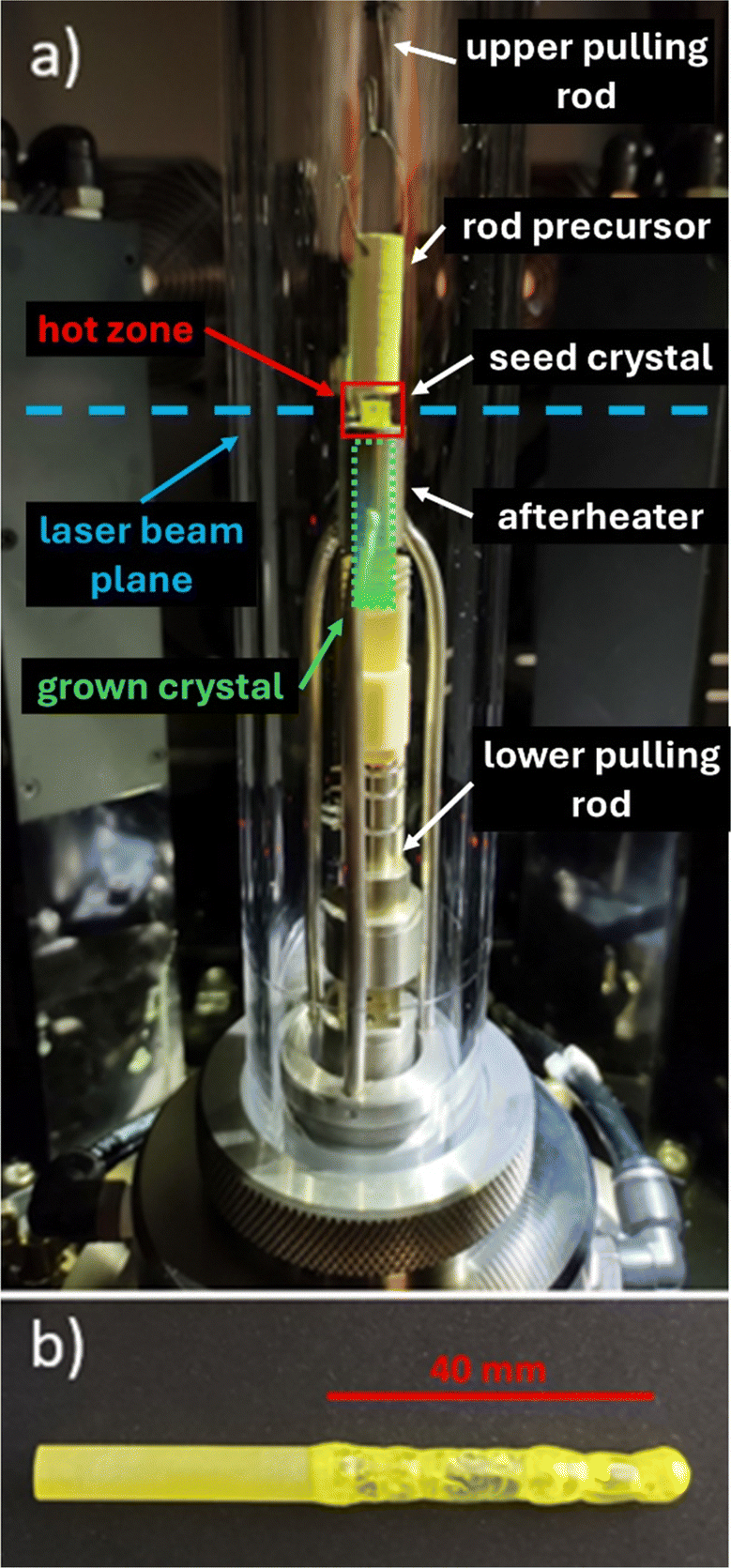 | ||
| Fig. 2 Part (a) shows the arrangement of the single crystal growth of GGAG in a laser furnace using the afterheater. Part (b) shows a 40 mm long GGAG:Ce single crystal produced in a laser furnace. | ||
Sample preparation
Six samples were cut from each crystal, two in the beginning part, two in the middle part and two in the ending part. Samples are in the shape of cylinders, diameter as grown (∼7 mm), thickness of 1 mm and polished on parallel sides.Optical properties measurement
Absorption spectra were measured using the UV/VIS/NIR Spectrophotometer Shimadzu 3101PC in the range 190–800 nm. Radioluminescence (RL), photoluminescence excitation (PLE) and emission (PL) spectra and PL decay curves were measured by a custom-made spectrofluorometer 5000M (Horiba Jobin Yvon) using a W X-ray tube (40 kV, 15 mA, Seifert), steady-state xenon lamp (EQ-99X LDLS – Energetic, a Hamamatsu Company), and nanosecond nanoLED pulsed light sources (IBH Scotland) as the excitation sources, respectively. Fast decays were measured by a time-correlated single-photon counting technique. The detection part of the setup involved a single-grating monochromator and a photon-counting detector TBX-04 (IBH Scotland). Measured spectra were corrected for the spectral dependence of detection sensitivity (RL, PL) and of excitation energy (PLE). The convolution procedure was applied to the photoluminescence and scintillation decay curves to determine true decay times (SpectraSolve software package, Ames Photonics). For every RL spectrum, a BGO standard crystal scintillator of similar dimensions was measured under the same experimental conditions as well to obtain quantitative intensity information.A routine spectrally unresolved scintillation decay was measured by means of fast photomultiplier (PMT) R7207-01, Hamamatsu working in the current regime, and a Keysight InfiniiVision DSOX6002A digital oscilloscope where the sample was optically coupled directly to the PMT photocathode.
Scintillation light yield (LY) was determined by the pulse height spectroscopy of the scintillation response, using the HPMT (Hybrid Photomultiplier) model DEP PPO 475C, spectroscopy amplifier ORTEC model 672 (shaping time t = 1 μs) and multichannel buffer ORTEC 927TM. The sample was optically coupled to HPMT using a silicon grease; and several layers of Teflon tape were put over the sample as a reflector. Photoelectron yield (PhY) was obtained from the Gaussian fit of the photopeak in the pulse-height spectra. Quantum efficiency (QE) for both samples was calculated using RL spectra. Finally, light yield was calculated as eqn (1):
| LY = PhY/QE | (1) |
3 Theoretical calculations of the electronic band structure
The first principles calculations were performed using the VASP code,55 based on the density functional theory (DFT) and the projector augmented wave (PAW) method.56 The total number of atoms in all supercells of pure Gd3Al5O12, Gd3Ga5O12 and mixed Gd3Al2.3Ga2.7O12 garnets is 160. The structure of the mixed garnet Gd3Al2.3Ga2.7O12 was obtained by replacing 22 Al atoms by Ga atoms in the ideal structure of Gd3Al5O12 (the total number of Al atoms in the Gd3Al5O12 unit cell is 40). The geometrical structure optimization of the pure Gd3Al5O12, Gd3Ga5O12 and mixed Gd3Al2.3Ga2.7O12 garnets was performed by using GGA-PBE57 and SCAN levels. The electronic structure of the pure Gd3Al5O12, Gd3Ga5O12 and mixed Gd3Al2.3Ga2.7O12 garnets was calculated by using the GGA-PBE, SCAN and Heyd–Scuseria–Ernzerhof (HSE)58 functionals. The plane-wave cutoff energy was chosen as 520 eV and the single Γ-point in the Brillouin zone was used for all models.4 Experimental results and discussion
Optical absorption spectra of GGAG:Ce and GGAG:Ce,Mg single crystals at room temperature are shown in Fig. 4. Clear structures can be seen in the investigated spectral range: (i) well-resolved transitions of Ce3+ 4f → 5d1 at 443 nm and 4f → 5d2 at 341 nm; (ii) sharp absorption peaks at 276 nm and 305–312 nm, attributed to 8S7/2 → 6Ix and 8S7/2 → 6Px transitions, respectively of Gd3+ ions; (iii) co-doping with Mg results in the appearance of the broad band attributed to the Ce4+ charge transfer absorption transition between 220 nm and 350 nm.17,19,59,60 In fact, CT absorption is observed even in the Mg-free sample when the spectrum is compared with a commercial GAGG:Ce sample, which is explained by Ce4+ stabilization due to the pressurized oxygen atmosphere in the growth process. The bandgap edge can be seen at 210 nm, well in correspondence with previously published data.5Scintillation properties
RT radioluminescence spectra of GGAG:Ce and GGAG:Ce,Mg single crystals are shown and compared to the standard BGO scintillator in Fig. 3. We can see one emission band originating from the Ce3+ 5d1 → 4f transition at 525 nm.3 When comparing the spectral integrals with the BGO standard sample one, GGAG:Ce shows 485% of its integral intensity and GGAG:Ce,Mg 70% of that of BGO. In the inset, the magnified GGAG:Ce spectrum below 400 nm is shown where the traces of Gd3+ (at 275 nm and 312 nm) and accidental Tb3+ impurity emissions (at 381 nm) are seen.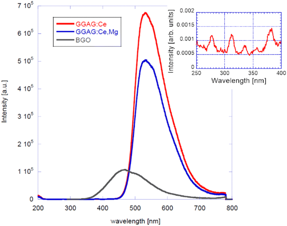 | ||
| Fig. 3 Radioluminescence spectra of GGAG:Ce and GGAG:Ce,Mg measured at RT, compared with BGO. | ||
 | ||
| Fig. 4 Optical absorption spectrum of GGAG:Ce (left) and of GGAG:Ce,Mg (right) at RT. | ||
Fig. 5 shows the spectrally unresolved scintillation decay of both GGAG:Ce and GGAG:Ce,Mg single crystals, excited by a 137Cs radioisotope source (662 keV). The decay curves are approximated by the sum of two exponentials in the following form (eqn (2)):
 | (2) |
 | (3) |
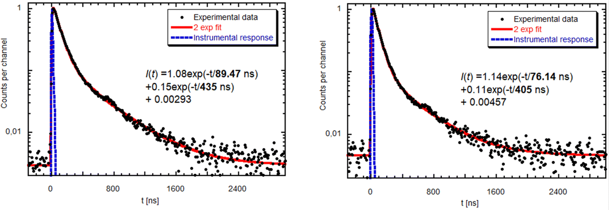 | ||
| Fig. 5 Scintillation decay of GGAG:Ce (left) and GGAG:Ce,Mg (right) excited by a 137Cs radioisotope at RT. Red line is the convolution of function I(t) and instrumental response. | ||
The values of the light sum for each component are in Table 1. The scintillation response in the Mg co-doped material is faster as the decay time constants of the fast component are shorter, and the light sum of the faster component is higher. This acceleration is due to Mg co-doping which stabilizes Ce4+ in higher concentration, in line with ref. 17 and 18. Nevertheless, in the case of the Mg-free sample, the decay is noticeably faster compared to the Czochralski-grown sample with the same host composition,5 which can be explained just by the stabilization of the Ce4+ centre due to the oxygen-rich growth atmosphere.
| Crystal composition | T1 [ns] | LS1 [%] | T2 [ns] | LS2 [%] | LY (EnRes) [ph/MeV (%)] |
|---|---|---|---|---|---|
| GGAG:Ce | 89.5 | 60.5 | 435 | 39.5 | 42000 (9.8) |
| GGAG:Ce,Mg | 76.1 | 65.6 | 405 | 34.4 | 38100 (10.0) |
Measured and normalized afterglow curves of GGAG:Ce and GGAG:Ce,Mg are shown and compared with the BGO reference in Fig. 6 (left). BGO is generally considered as a scintillator that exhibits extremely low afterglow61 with nearly five orders of magnitude drop in signal intensity after X-ray cut/off in the figure. Our samples exhibit more than three orders of magnitude signal drop after X-ray cut-off so that the afterglow is certainly not a detrimental issue in their scintillation performance.
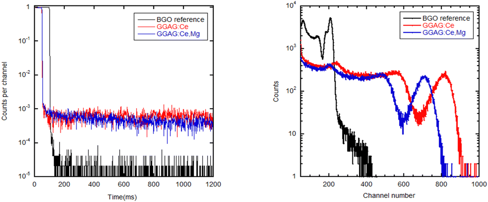 | ||
| Fig. 6 RT spectrally unresolved afterglow curve of GGAG:Ce, GGAG:Ce,Mg and BGO standard, excitation by 40 kV X-ray (left) and pulse-height spectra for GAGG:Ce, GGAG:Ce,Mg and BGO under γ-ray excitation from 137Cs radioisotope (662 keV). | ||
Fig. 6 (right) shows the pulse-height spectra comparison among both GGAG:Ce and GGAG:Ce,Mg samples and the BGO reference. The shaping time was set to be 1 μs. Calculated scintillation light yield values are shown in Table 1. The somewhat lower light yield value in the Mg-codoped crystal can be explained by two effects: (i) Ce3+–Mg2+ pairs can be formed, which decrease the energy barrier for thermal quenching of Ce3+ emission;62 (ii) the overlap of the Gd3+ absorption/emission multiplet 8S → 6Px within 305–312 nm with the charge absorption of Ce4+ in this region (see Fig. 4 left) can cause energy leakage from the Gd3+ sublattice towards the non-luminescent charge transfer absorption transition of Ce4+.
The achieved scintillation properties of the GGAG:Ce single crystal can hardly be compared with the literature, because the studied crystals of given composition have never been prepared by a floating zone method, with similar Al/Ga ratio and Ce dopant concentration. On top of that, to our knowledge, our samples are the first ones ever prepared by the laser-diode floating zone method. Nevertheless, our samples overcame the scintillation response of samples prepared in halogen mirror furnaces from previous papers51,52 in terms of the fast scintillation time component. Scintillation light yield could not be compared as it was not studied in the mentioned papers.
Samples in paper ref. 37 are characterized by a similarly fast scintillation time component (71–88 ns) as ours, but a higher light sum (calculated by eqn (3)) of the fast component has been achieved (80–88% compared to our 60%). Our material beats them in terms of scintillation light yield. We achieved a scintillation light yield as high as 42000 ph per MeV, which is 8000 ph per MeV more when compared to the as-grown samples and 3000 ph per MeV more when compared to their samples after annealing in ref. 37.
When compared with the state of art GGAG-based scintillators grown by conventional Czochralski methods,63–65 their effective scintillation decay times are within 60–140 ns and the scintillation light yield varies from 28000 to 50000 ph per MeV. It is safe to say, that our samples are perfectly competitive with them in terms of simultaneous consideration of scintillation speed and light yield.
Photoluminescence measurements
Photoluminescence excitation and emission spectra of GGAG:Ce and GGAG:Ce,Mg single crystals at RT are shown in Fig. 7. Photoluminescence excitation spectra, measured at λem = 530 nm, are dominated by Ce3+ 4f → 5d1 (443 nm) and 4f → 5d2 (341 nm), well in agreement with the absorption spectra (see Fig. 4), while photoluminescence emission spectra, measured with λex = 340 nm, are composed of a broad band peaking at 530 nm, whose origin is in the Ce3+ 5d1 → 4f transition and it is in good agreement with radioluminescence spectra shown in Fig. 3. Comparatively less effective excitation below 350 nm in GGAG:Ce,Mg is due to competing CT absorption (see Fig. 4). | ||
| Fig. 7 RT photoluminescence excitation for emission wavelength 530 nm (left) and emission (right) spectra of GGAG:Ce and GGAG:Ce,Mg for excitation wavelength 340 nm. | ||
Fig. 8 shows the RT photoluminescence decay curve of the Ce3+ 4f → 5d1 emission (λex = 454 nm, λem = 530 nm) of GGAG:Ce and GGAG:Ce,Mg single crystals. The evaluated decay times are very close to literature values taking into account their dependence on host composition.13,66
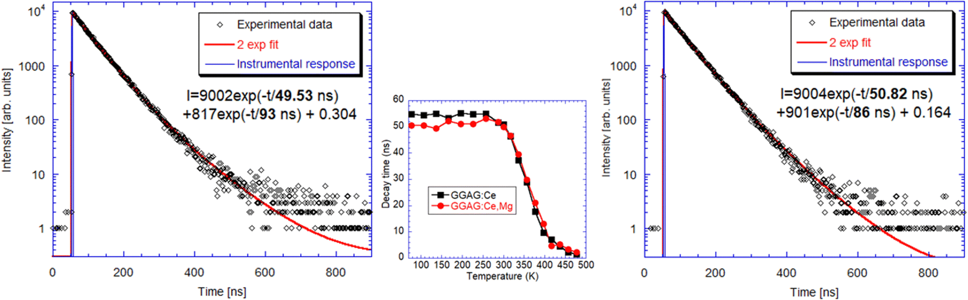 | ||
| Fig. 8 RT photoluminescence decay curve connected to Ce3+ 4f → 5d1 emission (λex = 454 nm, λem = 530 nm) of GGAG:Ce (left) and GGAG:Ce,Mg (right). Solid line is a convolution of the instrumental response and function I(t) in the figure. In the inset, the temperature dependence of the faster component decay time is shown for both samples. | ||
Photoluminescence measurements were further completed by the decays of the Gd3+ 312 nm emission line at room temperature, Fig. 9, to see possible correspondence with the slower component in scintillation decay. Such a component could arise due to energy migration over the Gd-sublattice as it has been reported in the literature that there is an efficient energy transfer from the GAGG host lattice exciton state in GAGG:Ce to the Gd3+ cation.67
 | ||
| Fig. 9 PL decay of the Gd3+ 312 nm emission line under excitation at 275 nm. | ||
PL decay in Fig. 9 shows a clear sign of the presence of a submicrosecond component, which is consistent with a possible correlation with a slower component (400–450 ns) appearance in scintillation decay in Fig. 5, though, very probably it will not be the only reason for its existence. Interestingly, in Fig. 9, there is also a very slow component with around 1 ms decay time which is close to the decay time of an isolated Gd3+ centre 312 nm emission (e.g. 3.18 ms in undoped GdY2GaAl4O1268). This points to possible decoupling of parts of the Gd-sublattice preventing fast migration of energy towards the Ce3+ centres, which could be accomplished e.g. by Gd vacancies in the structure.
Thermoluminescence measurements
To monitor electron traps active in the scintillation mechanism, thermoluminescence measurements after X-ray irradiation at 77 K were made in 77–500 K in which these samples were compared to the commercial GAGG:Ce sample, Fig. 10. Despite lower optical quality (tiny cracks in the volume of less transparent parts of the crystal in Fig. 2(b)), the LDFZM-made samples show much lower intensity in TSL glow curves, which evidences lower trap concentrations considering their high LY, i.e. the low influence of any quenching centres in the host lattice. There is also great similarity in the position of the glow curve peaks among all three samples, which points to the common nature of the traps involved. The lower intensity of the peaks of GAGG:Ce,Mg compared to GAGG:Ce, when LDFZM-made samples are compared, can be explained by the positive influence of the stabilized Ce4+ centres in the former, which directly compete with electron traps for electron capture.17 Lower trap concentrations in LDFZM-made GAGG:Ce compared to the commercial one, even though the better optical quality of the latter can consist in lower concentration of oxygen vacancies and better stoichiometry of the former due to pressurized oxygen atmosphere in the crystal growth process.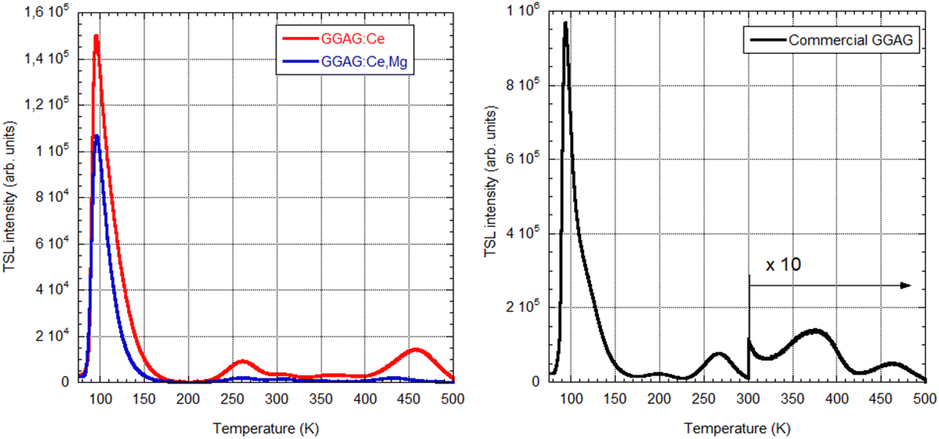 | ||
| Fig. 10 Thermoluminescence measurements of LFZM/made samples (left) and a commercial GAGG:Ce one (right) after X-ray irradiation at 77 K (spectrally unresolved). All measurements are comparable in an absolute scale. | ||
5 First principles calculation: results and discussion
The crystal structures of the pure and mixed garnet compositions (the details of the structural models are given in the description of the calculation method in Section 3) were optimized within the GGA and SCAN functionals; the GGA and SCAN-calculated lattice parameters are shown in Table 2. The calculations within the local density approximation (LDA) and generalized gradient approximation (GGA) functionals do not provide a high enough accuracy from the point of view of agreement between the calculated and experimental values of the lattice constants. It is known that the application of the SCAN functionals in the calculations can lead to improved values of the optimized structural constants. However, the band gap of crystalline solids calculated by the SCAN functionals is much smaller compared to the experimental values. To overcome this issue, the use of the hybrid functional can be recommended for a better description of the electronic structure of solids, and the band gap estimations with the HSE06 functional become more accurate. It should be mentioned that the HSE06-based calculations are very time-consuming, that is why only the electronic structure was calculated within the HSE06 functionals, using optimized geometric structures optimized with SCAN as an input for the band structure calculations. The GGA, SCAN and HSE06 calculated band gaps are shown in Table 3. The calculated lattice parameters and the band gap energy of the mixed garnet Gd3Al2.3Ga2.7O12 are between the corresponding values for Gd3Al5O12 and Gd3Ga5O12. The HSE06 calculated band gap of Gd3Al2.3Ga2.7O12 is close to the experimental values of Gd3GaxAl5−xO12 (x = 2, 3) from ref. 5.| System | Lattice parameter | Calc. [Å] | Exp. [Å] | |
|---|---|---|---|---|
| GGA | SCAN | |||
| Gd3Al5O12 | a = b = c | 12.173 | 12.042 | |
| Gd3Ga5O12 | a = b = c | 12.482 | 12.328 | 12.38969 |
| Gd3Al2.3Ga2.7O12 | a | 12.318 | 12.179 | |
| b | 12.348 | 12.204 | ||
| c | 12.363 | 12.217 | ||
| System | Calc. [eV] | Exp. [eV] | ||
|---|---|---|---|---|
| GGA | SCAN | HSE06 | ||
| Gd3Al5O12 | 4.3839 | 4.8584 | 5.9790 | |
| Gd3Ga5O12 | 3.2170 | 4.0195 | 5.2375 | 5.38 (x = 0) |
| Gd3Al2.3Ga2.7O12 | 3.7854 | 4.5885 | 5.7743 | 5.88 (x = 2)–6.01 (x = 3) |
Smooth variation of the chemical composition in the studied garnets leads to a linear variation of the lattice constant and band gaps (Vegard law), as Fig. 11 and Fig. 12 show. Replacement of Al by Ga results in an increase of the lattice constant (due to a greater ionic radius of Ga) and a decrease of the band gap. In the case of the mixed garnet, the averaged values of the a, b and c constants were taken for the visualization. The correlation coefficients of the linear fits are 0.999 in the case of the lattice constants and vary from 0.99 to 0.82 in the case of the band gaps. It should be mentioned here that quite often band gaps deviate from Vegard's law70 due to the band gap bowing effects.
 | ||
| Fig. 11 Calculated (this work) lattice constants in Å as a function of Al concentration (in %) in the studied garnets. Empty symbols show the experimental data from ref. 5. Equations of linear fits are shown. | ||
 | ||
| Fig. 12 Calculated band gaps (in eV) as a function of Al concentration (in %) in the studied garnets. Equations of linear fits are shown. | ||
The total density of states diagrams, calculated with different functionals, are shown in the ESI† file for Gd3Al2.3Ga2.7O12 in Fig. S1 in the ESI,† while its partial density of states diagrams calculated by HSE0 are depicted in Fig. S2 in the ESI.† Using GGA, the partial density of states is calculated for Gd3Al5O12 and Gd3Ga5O12 in Fig. S3 and S4 in the ESI,† respectively. The valence band in all studied garnets is dominated by the oxygen 2p states, as can be anticipated. The conduction bands are formed by the unoccupied metal states. The partially filled 4f states of Gd ions are in the valence band.
The electronic properties of these multicomponent garnets are of special interest. It was noticed a significant decrease in their band gap that is related to the contribution of both the Ga and Gd ions in the system. The bottom of the conduction band is predominantly made by the states belonging to Ga ions, whereas the energy states of lighter Al ions are located in the upper part of the conduction band.
Conclusions
We, for the first time, have successfully prepared GGAG:Ce and GGAG:Ce,Mg single crystals by the laser-diode floating zone method in oxygen atmosphere over-pressure 0.3 MPa. The measurements conclude that our samples are perfectly competitive in terms of simultaneous consideration of scintillation speed and light yield with both the experimental and commercial single crystals grown by the Czochralski method and even single crystals prepared by an optical floating zone. Codoping with Ce, and Mg resulted in scintillation response acceleration at the cost of slightly decreased light yield, well in agreement with the literature.The performed first-principles calculations have shown that the band gap of these multicomponent garnets is decreased with partial replacement of the Al by Ga. Such a band gap variation diminishes charge carrier capture in the scintillation mechanism (the relevant electron trap energy levels become hidden in the conduction band) and further enables their fast and effective migration towards Ce3+ centres in addition to the energy delivered to the Ce3+ centres through the Gd sublattice. The participation of the latter mechanism is supported by the observed close decay time values of the slower component in scintillation decay and the fastest component in the Gd3+ 312 nm emission line decay. Interestingly, the appearance of slow ms decay time in 312 nm emission line decay points to the decoupling of some Gd3+ cations from the energy migration process which might be caused by defects (Gd vacancies). Thus, the overall energy transport towards the Ce3+ centres in the GGAG host occurs by the prompt charge carrier transport through the conduction band and the delayed one accomplished by energy migration through the Gd-sublattice. The participation of various charge carrier trapping centres in the transport stage of the scintillation mechanism was visualized in thermoluminescence glow curves which are of distinctly lower intensity in crystals grown by the laser-diode floating zone method compared to the commercial Czochralski grown one.
Reported results show the significant advantage of utilising the (laser-diode) floating zone method for the preparation of various oxide-based scintillator and laser materials as it allows single crystal growth without costly crucibles and unprecedented usage of the oxygen overpressure, which is unattainable by both the Czochralski and micro-pulling-down method.
Author contributions
František Zajíc: investigation, data curation, writing – original draft, writing – review & editing, visualization. Vítězslav Jarý: writing – original draft, writing – review & editing. Jiří Pospíšil: writing – review & editing, supervision, project administration, funding acquisition. Pavel Boháček: resources. Zafari Umar: software, formal analysis, investigation, data curation. Michal Piasecki: software, formal analysis, investigation, data curation. Mikhail G. Brik: conceptualization, methodology, formal analysis, writing – review & editing. Romana Kučerková: investigation, data curation. Alena Beitlerová: investigation, data curation. Martin Nikl: conceptualization, writing – review & editing, project administration, funding acquisition.Data availability
The data related to figures are available upon request from the corresponding authors.Conflicts of interest
The authors declare that they have no known competing financial interests or personal relationships that could have appeared to influence the work reported in this paper.Acknowledgements
The work was supported by the Czech Science Foundation under Grant No. 21-17731S and HE EIC project Unicorn no. 101098649. The work of F. Z. was further supported by Charles University Grant Agency (Project No. 294123). The preparation of single crystals was performed in MGML (https://mgml.eu/), which was supported within the program of Czech Research Infrastructures (Project No. LM2023065). M. G. B. appreciates the support from the Ministry of Science, Technological Development, and Innovation of the Republic of Serbia under contract 451-03-47/2023-01/200017, Specialized Funding Program for the Gathering of 100 Elite Talents in Chongqing and the Overseas Talents Plan (Grant No. 2022[60]) both offered by Chongqing Association for Science and Technology and Estonian Research Council grant (PRG 2031). This work was partially supported by the National Science Centre, Poland, grant SHENG 2 number: 2021/40/Q/ST5/00336, and the National Natural Science Foundation of China (Grant No. 52161135110).References
- M. Nikl and A. Yoshikawa, Adv. Opt. Mater., 2015, 3, 463–481 CrossRef CAS.
- C. Dujardin, E. Auffray, E. Bourret-Courchesne, P. Dorenbos, P. Lecoq, M. Nikl, A. N. Vasil'ev, A. Yoshikawa and R. Y. Zhu, IEEE Trans. Nucl. Sci., 2018, 65, 1977–1997 CAS.
- K. Kamada, T. Yanagida, T. Endo, K. Tsutumi, Y. Usuki, M. Nikl, Y. Fujimoto, A. Fukabori and A. Yoshikawa, J. Cryst. Grow., 2012, 352, 88–90 CrossRef CAS.
- K. Kamada, S. Kurosawa, P. Prusa, M. Nikl, V. V. Kochurikhin, T. Endo, K. Tsutumi, H. Sato, Y. Yokota and K. Sugiyama, Opt. Mater., 2014, 36, 1942–1945 CrossRef CAS.
- D. Spassky, F. Fedyunin, E. Rubtsova, N. Tarabrina, V. Morozov, P. Dzhevakov, K. Chernenko, N. Kozlova, E. Zabelina and V. Kasimova, Opt. Mater., 2022, 125, 112079 CrossRef CAS.
- K. Brylew, W. Drozdowski, A. J. Wojtowicz, K. Kamada and A. Yoshikawa, J. Lumin., 2014, 154, 452–457 CrossRef CAS.
- P. Dorenbos, J. Lumin., 2013, 134, 310–318 CrossRef CAS.
- M. Kitaura, H. Zen, K. Kamada, S. Kurosawa, S. Watanabe, A. Ohnishi and K. Hara, Appl. Phys. Lett., 2018, 112, 031112 CrossRef.
- V. Kochurikhin, K. Kamada, K. J. Kim, M. Ivanov, L. Gushchina, Y. Shoji, M. Yoshino and A. Yoshikawa, J. Cryst. Grow., 2020, 531, 125384 CrossRef CAS.
- V. Laguta, Y. Zorenko, V. Gorbenko, A. Iskaliyeva, Y. Zagorodniy, O. Sidletskiy, P. Bilski, A. Twardak and M. Nikl, J. Phys. Chem. C, 2016, 120, 24400–24408 CrossRef CAS.
- M. Li, M. Meng, J. Chen, Y. Sun, G. Cheng, L. Chen, S. Zhao, B. Wan, H. Feng, G. Ren and D. Ding, Phys. Status Solidi B, 2021, 258, 2000603 CrossRef CAS.
- S. Nargelas, Y. Talochka, A. Vaitkevičius, G. Dosovitskiy, O. Buzanov, A. Vasil'ev, T. Malinauskas, M. Korzhik and G. Tamulaitis, J. Lumin., 2022, 242, 118590 CrossRef CAS.
- J. M. Ogiegło, A. Katelnikovas, A. Zych, T. Justel, A. Meijerink and C. R. Ronda, J. Phys. Chem. A, 2013, 117, 2479–2484 CrossRef.
- O. Sidletskiy, V. Kononets, K. Lebbou, S. Neicheva, O. Voloshina, V. Bondar, V. Baumer, K. Belikov, A. Gektin and B. Grinyov, Mater. Res. Bull., 2012, 47, 3249–3252 CrossRef CAS.
- I. I. Vrubel, R. G. Polozkov, I. A. Shelykh, V. M. Khanin, P. A. Rodnyi and C. R. Ronda, Cryst. Growth Des., 2017, 17, 1863–1869 CrossRef CAS.
- C. Wang, D. Ding, Y. Wu, H. Li, X. Chen, J. Shi, Q. Wang, L. Ye and G. Ren, Appl. Phys. A: Mater. Sci. Process., 2017, 123, 1–6 CrossRef.
- M. Nikl, K. Kamada, V. Babin, J. Pejchal, K. Pilarova, E. Mihokova, A. Beitlerova, K. Bartosiewicz, S. Kurosawa and A. Yoshikawa, Cryst. Growth Des., 2014, 14, 4827–4833 CrossRef CAS.
- Y. Wu, F. Meng, Q. Li, M. Koschan and C. L. Melcher, Phys. Rev. Appl., 2014, 2, 044009 CrossRef CAS.
- K. Kamada, M. Nikl, S. Kurosawa, A. Beitlerova, A. Nagura, Y. Shoji, J. Pejchal, Y. Ohashi, Y. Yokota and A. Yoshikawa, Opt. Mater., 2015, 41, 63–66 CrossRef CAS.
- G. Tamulatis, G. Dosovitskiy, A. Gola, M. Korjik, A. Mazzi, S. Nargelas, P. Sokolov and A. Vaitkevičius, J. Appl. Phys., 2018, 124, 215907 CrossRef.
- M. Korzhik, V. Alenkov, O. Buzanov, G. Dosovitskiy, A. Fedorov, D. Kozlov, V. Mechinsky, S. Nargelas, G. Tamulaitis and A. Vaitkevičius, CrystEngComm, 2020, 22, 2502–2506 RSC.
- Y.-N. Xu, W. Ching and B. Brickeen, Phys. Rev. B: Condens. Matter Mater. Phys., 2000, 61, 1817 CrossRef CAS.
- O. Sidletskiy, P. Arhipov, S. Tkachenko, I. Gerasymov, D. Kurtsev, V. Jarý, R. Kučerková, M. Nikl, K. Lebbou and E. Auffray, in Engineering of Scintillation Materials and Radiation Technologies (ISMART 2018), Springer, Berlin, 2019, pp. 83–95 Search PubMed.
- D. Kofanov, I. Gerasymov, O. Sidletskiy, S. Tkachenko, Y. Boyaryntseva, D. Kurtsev, O. Zelenskaya, O. Okrushko, T. Gorbacheva, O. Viagin, P. Maksimchuk and K. Lebbou, Opt. Mater., 2022, 134, 113176 CrossRef CAS.
- O. Sidletskiy, I. Gerasymov, Y. Boyaryntseva, P. Arhipov, S. Tkachenko, O. Zelenskaya, K. Bryleva, K. Belikov, K. Lebbou, C. Dujardin, B. Büchner and B. Grynyov, Cryst. Growth Des., 2021, 21, 3063–3070 CrossRef CAS.
- A. Nagura, K. Kamada, M. Nikl, S. Kurosawa, J. Pejchal, Y. Yokota, Y. Ohashi and A. Yoshikawa, Jpn. J. Appl. Phys., 2015, 54, 04DH17 CrossRef.
- O. Zapadlík, M. Nikl, J. Polák, P. Průša and V. Linhart, Opt. Mater.: X, 2022, 15, 100165 Search PubMed.
- L. Martinazzoli, S. Nargelas, P. Boháček, R. Calá, M. Dušek, J. Rohlíček, G. Tamulaitis, E. Auffray and M. Nikl, Mater. Adv., 2022, 3, 6842–6852 RSC.
- E. V. Zharikov, J. Cryst. Grow., 2012, 360, 146–154 CrossRef CAS.
- W. Zhao, J. Li and L. Liu, Crystals, 2021, 11, 264 CrossRef CAS.
- K. Bartosiewicz, A. Markovskyi, T. Horiai, D. Szymański, S. Kurosawa, A. Yamaji, A. Yoshikawa and Y. Zorenko, J. Alloys Compd., 2022, 905, 164154 CrossRef CAS.
- A. Revcolevschi and J. Jegoudez, Prog. Mater. Sci., 1997, 42, 321–339 CrossRef CAS.
- S. Kimura and K. Kitamura, J. Am. Ceram. Soc., 1992, 75, 1440–1446 CrossRef CAS.
- S. Kimura, K. Kitamura and I. Shindo, J. Cryst. Grow., 1983, 65, 543–548 CrossRef CAS.
- S. Kimura and I. Shindo, J. Cryst. Grow., 1977, 41, 192–198 CrossRef CAS.
- S. Kimura, I. Shindo, K. Kitamura, Y. Mori and H. Takamizawa, J. Cryst. Grow., 1978, 44, 621–624 CrossRef CAS.
- T. Wu, L. Wang, Y. Shi, T. Xu, H. Wang, J. Fang, J. Ni, H. He, C. Wang, B. Wan, D. Ding, Z. Zhou, Q. Liu, Q. Li, J. Yu, X. Huang, O. Shichalin and E. K. Papynov, Cryst. Growth Des., 2021, 22, 180–190 CrossRef.
- L. Abernethy, T. Ramsey Jr and J. W. Ross, J. Appl. Phys., 1961, 32, S376–S377 CrossRef.
- K. Vlášková, R. Colman, P. Proschek, J. Čapek and M. Klicpera, Phys. Rev. B, 2019, 100, 214405 CrossRef.
- M. Kawata, H. Toshima, Y. Miyazawa and S. Morita, J. Cryst. Grow., 1993, 128, 1011–1015 CrossRef CAS.
- F. Rey-García, R. Ibáñez, L. A. Angurel, F. M. Costa and G. F. de la Fuente, Crystals, 2020, 11, 38 CrossRef.
- T. Ito, T. Ushiyama, Y. Yanagisawa, Y. Tomioka, I. Shindo and A. Yanase, J. Cryst. Grow., 2013, 363, 264–269 CrossRef CAS.
- J. Stone, C. A. Burrus, A. G. Dentai and B. I. Miller, Appl. Phys. Lett., 1976, 29, 37–39 CrossRef CAS.
- M. M. Fejer, J. L. Nightingale, G. A. Magel and R. L. Byer, Rev. Sci. Instrum., 1984, 55, 1791–1796 CrossRef CAS.
- P. Rudolph and T. Fukuda, Cryst. Res. Technol., 1999, 34, 3–40 CrossRef CAS.
- G. Maxwell, B. Ponting, E. Gebremichael and R. Magana, Crystals, 2017, 7, 12 CrossRef.
- C. Nie, S. Bera, J. Melzer, J. Harrington, E. F. Dreyer, S. Rand, S. Trembath-Reichert and C. Hoef, SPIE LASE, 2015, 9342, 934204 Search PubMed.
- Y. Shen, S. Chen, W. Zhao and J. Chen, Photonics Asia, 2002, 4918, 20–29 Search PubMed.
- F. Rey-García, N. B. Sedrine, A. J. S. Fernandes, T. Monteiro and F. M. Costa, J. Eur. Ceram. Soc., 2018, 38, 2059–2067 CrossRef.
- A. Yoshikawa, V. Kochurikhin, M. Yoshino, R. Murakami, T. Tomida, I. Takahashi, T. Horiai, K. Kamada, Y. Shoji, H. Sato, R. Kucerkova, A. Beitlerova and M. Nikl, Cryst. Growth Des., 2023, 23, 2048–2054 CrossRef.
- A. Suzuki, S. Kurosawa, J. Pejchal, V. Babin, Y. Fujimoto, A. Yamaji, M. Seki, Y. Futami, Y. Yokota, K. Yubuta, T. Shishido, M. Kikuchi, M. Nikl and A. Yoshikawa, Phys. Status Solidi C, 2012, 9, 2251–2254 CrossRef CAS.
- A. Yoshikawa, Y. Fujimoto, A. Yamaji, S. Kurosawa, J. Pejchal, M. Sugiyama, S. Wakahara, Y. Futami, Y. Yokota and K. Kamada, Opt. Mater., 2013, 35, 1882–1886 CrossRef CAS.
- F. Zajic, M. Klejch, A. Elias, M. Klicpera, A. Beitlerova, M. Nikl and J. Pospisil, Cryst. Growth Des., 2023, 23, 2609–2618 CrossRef CAS PubMed.
- A. Yoshikawa, M. Nikl, G. Boulon and T. Fukuda, Opt. Mater., 2007, 30, 6–10 CrossRef CAS.
- G. Kresse and J. Hafner, Phys. Rev. B: Condens. Matter Mater. Phys., 1993, 47, 558–561 CrossRef CAS PubMed.
- G. Kresse and D. Joubert, Phys. Rev. B: Condens. Matter Mater. Phys., 1999, 59, 1758–1775 CrossRef CAS.
- J. P. Perdew, A. Ruzsinszky, G. I. Csonka, O. A. Vydrov, G. E. Scuseria, L. A. Constantin, X. Zhou and K. Burke, Phys. Rev. Lett., 2008, 100, 136406 CrossRef PubMed.
- J. Heyd, G. E. Scuseria and M. Ernzerhof, J. Chem. Phys., 2006, 124, 219906 CrossRef.
- G. Dantelle, G. Boulon, Y. Guyot, D. Testemale, M. Guzik, S. Kurosawa, K. Kamada and A. Yoshikawa, Phys. Status Solidi B, 2020, 257, 1900510 CrossRef CAS.
- V. Babin, P. Herman, M. Kucera, M. Nikl and S. Zazubovich, J. Lumin., 2019, 215, 116608 CrossRef CAS.
- T. Yanagida, Y. Fujimoto, T. Ito, K. Uchiyama and K. Mori, Appl. Phys. Express, 2014, 7, 062401 CrossRef CAS.
- V. Babin, P. Bohacek, M. Nikl, L. Vasylechko and S. Zazubovich, Opt. Mater., 2024, 154, 115691 CrossRef CAS.
- T. Yanagida, K. Kamada, Y. Fujimoto, H. Yagi and T. Yanagitani, Opt. Mater., 2013, 35, 2480–2485 CrossRef CAS.
- P. Sibczynski, J. Iwanowska-Hanke, M. Moszyński, L. Swiderski, M. Szawłowski, M. Grodzicka, T. Szczęśniak, K. Kamada and A. Yoshikawa, Nucl. Instrum. Methods Phys. Res., Sect. A, 2015, 772, 112–117 CrossRef CAS.
- L. Martinazzoli, N. Kratochwil, S. Gundacker and E. Auffray, Nucl. Instrum. Methods Phys. Res., Sect. A, 2021, 1000, 165231 CrossRef CAS.
- K. Kamada, T. Endo, K. Tsutumi, T. Yanagida, Y. Fujimoto, A. Fukabori, A. Yoshikawa, J. Pejchal and M. Nikl, Cryst. Growth Des., 2011, 11, 4484–4490 CrossRef CAS.
- V. Khanin, I. Venevtsev, K. Chernenko, V. Pankratov, K. Klementiev, T. van Swieten, A. J. van Bunningen, I. Vrubel, R. Shendrik and C. Ronda, J. Lumin., 2021, 237, 118150 CrossRef CAS.
- V. Babin, M. Nikl, K. Kamada, A. Beitlerova and A. Yoshikawa, J. Phys. D: Appl. Phys., 2013, 46, 365303 CrossRef.
- H. Sawada, J. Solid State Chem., 1997, 132, 300–307 CrossRef CAS.
- L. Vegard, Z. Phys., 1921, 5, 17–26 CrossRef CAS.
Footnote |
| † Electronic supplementary information (ESI) available. See DOI: https://doi.org/10.1039/d4ma00976b |
| This journal is © The Royal Society of Chemistry 2025 |