DOI:
10.1039/D4MA00966E
(Paper)
Mater. Adv., 2025,
6, 1414-1422
Reaction mechanism of atomic layer deposition of zirconium oxide using tris(dimethylamino)cyclopentadienyl zirconium: experimental and theoretical study†
Received
24th September 2024
, Accepted 13th January 2025
First published on 24th January 2025
Abstract
We investigated the reaction mechanism of atomic layer deposition (ALD) of zirconium oxide (ZrO2) by integrating experiments and calculations. The ALD process by alternating the supply of tris(dimethylamino)cyclopentadienyl zirconium (CpZr(NMe2)3) and ozone (O3) was examined using an in situ quartz crystal microbalance (QCM) and the successive surface reaction of the Zr precursor was simulated by density functional theory (DFT) calculations. The QCM analysis suggests that two NMe2 ligands are released during the first half-cycle of ALD. The DFT calculations indicate that the first two NMe2 ligands are released during the chemisorption of the Zr precursor with low activation energies of 0.22 eV and 0.16 eV. Conversely, the release of the Cp ligand or the third NMe2 ligand was unfavorable due to its endothermic nature and high activation energy. Upon completion of the chemisorption of the Zr precursor, the resulting surface species would be O2ZrCp(NMe2)*, which is in agreement with the QCM results. The integration of the QCM experiment and the DFT calculations is an effective approach to elucidate the ALD reaction mechanism, especially when a heteroleptic precursor is used.
Introduction
One promising approach to developing advanced precursors for atomic layer deposition (ALD) is to create heteroleptic metal–organic compounds in which two or more types of ligands are attached to a metal center.1–7 These heteroleptic ALD precursors are believed to possess advantages over homoleptic precursors, such as improved thermal stability while maintaining reactivity.8–11 A notable success was the combination of alkylamide and cyclopentadienyl ligands in a Zr compound to form tris(dimethylamino)cyclopentadienyl zirconium (CpZr(NMe2)3), which successfully replaced an alkylamide-based homoleptic Zr precursor, tetrakis(ethylmethylamino)zirconium (Zr(NEtMe)4), in the fabrication of dynamic random-access memory (DRAM) devices.9 In comparison to a homoleptic precursor of Zr(NEtMe)4, CpZr(NMe2)3 exhibits better thermal stability, resulting in better conformality at a high process temperature of 300 °C with a growth per cycle of ∼0.9 Å.8
The ALD process using CpZr(NMe2)3 and H2O has been examined by in situ quartz crystal microbalance (QCM) at 250 °C.12 The authors concluded that one Cp ligand per two Zr atoms remains adsorbed at the end of the precursor pulse. However, if this conclusion is correct, the Zr atoms are not sufficiently passivated by the ligands and interact with other Zr precursor molecules, which differs from the ideal ALD process in which the submonolayer grows in a self-limiting manner.
The surface reaction mechanisms of CpZr(NMe2)3 have also been investigated by density functional theory (DFT) calculations.13–15 The two successive ligand exchange reactions of CpZr(NMe2)3 with two surface OH groups were simulated using the (OH)2–Si21H24 cluster model, which mimics hydroxylated Si(100).13 The reactions were endothermic, making it challenging to elucidate the underlying mechanisms of film growth. In contrast, another study investigated the three successive ligand exchange reactions of CpZr(NMe2)3 with three surface OH groups using the (OH)4–Si15O10H16 cluster model, which mimics hydroxylated SiO2.14 The three reactions, which successively release three HNMe2 molecules, were plausible due to their exothermic nature and low activation energy values. The other study used the (OH)4–Si15H16 cluster model, which mimics the OH-terminated Si(100) surface, and also claimed that three ligand exchange reactions were exothermic, releasing three HNMe2 molecules.15 Consequently, both studies conclude that CpZr(NMe2)3 reacts with the surface to form −ZrCp*, where the asterisk denotes the surface species. However, this conclusion does not agree with the experiment, which expected a Cp per two Zr atoms.12 Since the models mimic OH-passivated Si or SiO2, the mechanism they studied would represent the initial stage of the ALD process. Furthermore, the studies did not consider the reactions that release the Cp ligand. No study has combined in situ characterization experiments and theoretical studies to gain a deeper understanding of the ALD process.
In this study, we investigated the surface reactions of CpZr(NMe2)3 precursor during the ALD of ZrO2 by combining in situ QCM experiments and DFT calculations. First, in situ QCM analysis was conducted to examine the surface species after the precursor dose. O3 was selected as the oxygen source due to shorter purge times than H2O16 and better step coverage than O2 plasma.17 Next, DFT calculations were performed to investigate the surface reactions of CpZr(NMe2)3 on ZrO2. The ZrO2 slab model previously employed in the DFT study using Zr(NMe2)418 was also utilized in the present study. The adsorption, reaction, and activation energies were calculated for the three successive surface reactions of CpZr(NMe2)3 with ZrO2. Furthermore, the atomistic geometries of the transition states were investigated and discussed. Finally, based on the results from the in situ QCM and DFT studies, the final chemisorbed species was predicted and compared with the results for Zr(NMe2)4 in the previous study.
Materials and methods
Experimental methods
ZrO2 films were grown using a hot-wall ALD reactor (iOV-fX2, ISAC Research Co. Ltd., Republic of Korea), and the film growth was monitored in real-time using a QCM system (SQM-160, INFICON, Switzerland) with a GaPO4 crystal resonator (R-30, Piezocrystal, Germany). The principles of in situ QCM measurements were initially established by Rocklein et al.19 and Sauerbrey et al.20 Further details regarding the methods and conditions were described in another publication.21 The canister containing CpZr(NMe2)3 (Hansol Chemical Co. Ltd., Republic of Korea) was maintained at 50 °C, and the precursor vapor was supplied in conjunction with Ar carrier gas (100 sccm). An ozone-oxygen mixture generated by an ozone generator (LAB-II, Ozonetech Co., Republic of Korea) was used as a co-reactant. The pulse times of CpZr(NMe2)3 and O3 were 7 s and 60 s, respectively. Ar gas served as the purge gas between precursor and reactant pulses. The process pressure was 1 torr. The average Δf0/Δf1 ratio was obtained from the examination during 17 ALD cycles.
Computational methods
The Dmol3 module in Material Studio 7.0 (BIOVIA, USA)22,23 was utilized for DFT calculations. The generalized gradient approximation and the Perdew–Burke–Ernzerhof exchange–correlation functional24 were employed with a numerical basis set of double numerical polarization 4.4. The core electrons of Zr atoms were treated with the DFT semi-core potential,25 and the DFT-D2 dispersion correction density functional was applied.26,27 The electron configurations for Zr, O, N, C, and H elements are as follows: Zr [Kr] 5s2 4d2, O [He] 2s2 2p4, N [He] 2s2 2p3, C [He] 2s2 2p2, and H 1s1. The effective core treatment was employed for Zr only. The convergence threshold and the thermal smearing were 1 × 10⁻⁵ Ha and 9 × 10⁻⁴ Ha, respectively. The Monkhorst–Pack scheme was implemented with a K-point grid sampling of 2 × 2 × 1 for the irreducible Brillouin zone. The convergence tolerance parameters for geometry optimization included a maximum displacement of 0.005 Å, a total energy change of 10−5 Ha, and an atomic force of 2 × 10⁻³ Ha Å−1. The complete linear-quadratic synchronous transit (LST-QST) or QST method was employed to determine the transition state28 with a root mean square (RMS) atomic force threshold of 0.002 Ha Å−1. The details of the transition state search method have been previously discussed in another publication.29
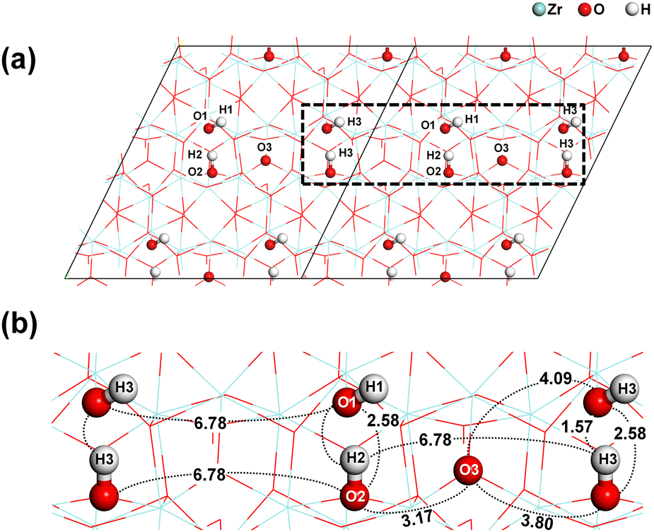
The substrate model that was previously used in our research was also employed in this study.18Fig. 1 shows a 2 × 2 supercell slab model of monoclinic ZrO2 (−111). The slab consists of 32 Zr, 72 O, and 16 H atoms. The top and bottom layers were passivated with eight OH groups, resulting in a surface OH density of 4.5 nm−2. The bottom half was fixed, while the top half was relaxed for all DFT calculations.
 |
| | Fig. 1 Schematic illustration of (a) the monoclinic ZrO2 (−111) slab model and (b) the reaction sites considered for the chemisorption of Zr precursor. Interatomic distances are given in Å. | |
For each reaction path, the reactant (R), product (P), and transition states (TS) were established. Additionally, the unbound reactant (UR) state, representing a system devoid of interaction between the precursor molecule and the substrate, was considered for the initial step of the chemisorption process. The energy of the UR state was calculated as the sum of the substrate energy (Esubstrate) and the isolated precursor energy (Eprecursor). The R1 state represents the physisorption of the Zr precursor, whereas R2 and R3 are the states where the first and second byproducts are removed, respectively. The product states with one, two, and three Zr–O bonds are P1, P2, and P3, respectively. TS1, TS2, and TS3 are transition states. The physisorption energy (Ephy), reaction energy (ΔEn), and activation energy (EAn) were defined as follows:
| | | Ephy = ER1 − (Esubstrate + Eprecursor) | (1) |
where
ERn,
EPn, and
ETSn are the system energies of
R,
P, and
TS of the
nth ligand release reaction.
The bond dissociation energy (BDE) was calculated using the same methodology employed in our previous publication.18 The ZrO2 slab was used to calculate the BDE of Zr–O and O–H, while the Zr precursor molecule was used for calculating the BDE of Zr–N.
Results and discussion
QCM analysis
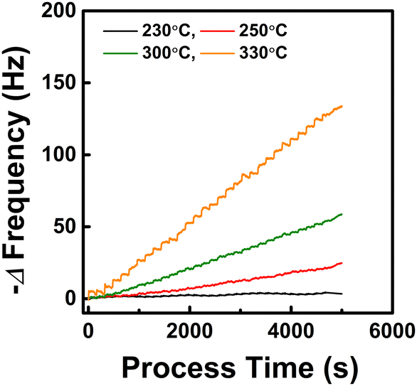
To investigate the reaction mechanism at temperatures representative of a genuine ALD process, we examined the temperature at which the precursor thermal decomposition is not observed. Fig. 2 shows the resonance frequency change when only the CpZr(NMe2)3 pulse and Ar purge are repeated in the temperature range of 230 °C to 330 °C without O3 supply. At 230 °C, the frequency showed a decrease during the initial cycles due to precursor chemisorption but remained nearly constant during the subsequent cycles. This suggests the self-limiting chemisorption of the precursor. Conversely, at 250 °C and above, the frequency continued to decrease with the number of cycles, indicating the mass increase due to thermal decomposition of the precursor. Therefore, the ALD process temperature was determined to be 230 °C for the QCM analysis of this work.
 |
| | Fig. 2 Resonance frequency change resulting from repeated CpZr(NMe2)3 pulses and Ar purges in the absence of the O3 supply. Process temperature was varied to identify the onset of the thermal decomposition of the precursor. | |
Fig. 3 shows the typical change in QCM resonance frequency that occurs by alternating the supply of CpZr(NMe2)3 and O3. The frequency change during one ALD cycle was 4.2 Hz, which corresponds to the GPC of 0.55 Å, assuming the film density of 4.86 g cm−3.30 The resonance frequency decrease observed during the CpZr(NMe2)3 pulse is primarily attributed to a mass increase by precursor chemisorption. In contrast, the frequency increase during the O3 pulse is due to a mass decrease by the combustion reaction, which forms an oxide film. Δf1 denotes the frequency change observed during the precursor pulse, while Δf0 represents the frequency change observed throughout a complete cycle. The Δf0/Δf1 values exhibited a nearly constant ratio of 0.64 ± 0.03.
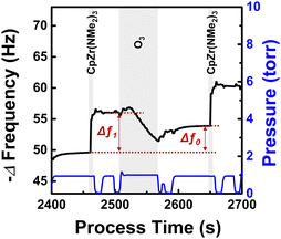 |
| | Fig. 3 Change in resonance frequency throughout the ZrO2 ALD process at 230 °C. CpZr(NMe2)3 and O3 were alternatingly supplied with pulse times of 7 s and 60 s, respectively. | |
For the first half-cycle of the ALD process, the reactions of the Cp and NMe2 ligands of CpZr(NMe2)3 with the hydroxyl groups on ZrO2 were assumed to occur, resulting in the release of HCp and HNMe2, respectively. The reaction equation is as follows:
| | | (x + y)–OH(s)* + CpZr(NMe2)3(g) → (–O–)(x+y)Cp1−xZr(NMe2)3−y(s)* + xHCp(g) + yHNMe2(g) | (4) |
where the variables
x and y represent the number of Cp and NMe
2 released, respectively. Subsequently, the Δ
f0/Δ
f1 ratios for all potential integer values of
x and
y were estimated by
eqn (5) in accordance with the methodology proposed by Matero
et al.31| |  | (5) |
where
m0 and
m1 denote the mass changes observed throughout a complete cycle and during the precursor pulse, respectively.
M represents the molecular weight (g mol
−1). The estimated Δ
f0/Δ
f1 ratio most closely approximating 0.64 was 0.67 with
x and
y of 0 and 2, respectively, as shown in
Table 1. Therefore, it can be suggested that CpZr(NMe
2)
3 underwent a reaction with the surface, resulting in the release of two HNMe
2 molecules, forming –O
2ZrCp(NMe
2)*.
Table 1 The Δf0/Δf1 ratios estimated by eqn (5) for all potential integer combinations of the number of Cp and NMe2 ligands released from a CpZr(NMe2)3 molecule during the first half-cycle of ZrO2 ALD
| Number of Cp released (x) |
Number of NMe2 released (y) |
Estimated Δf0/Δf1 |
| 0 |
0 |
0.46 |
| 0 |
1 |
0.54 |
| 0 |
2 |
0.67 |
| 0 |
3 |
0.86 |
|
|
| 1 |
0 |
0.59 |
| 1 |
1 |
0.75 |
| 1 |
2 |
1.00 |
| 1 |
3 |
1.52 |
DFT calculations
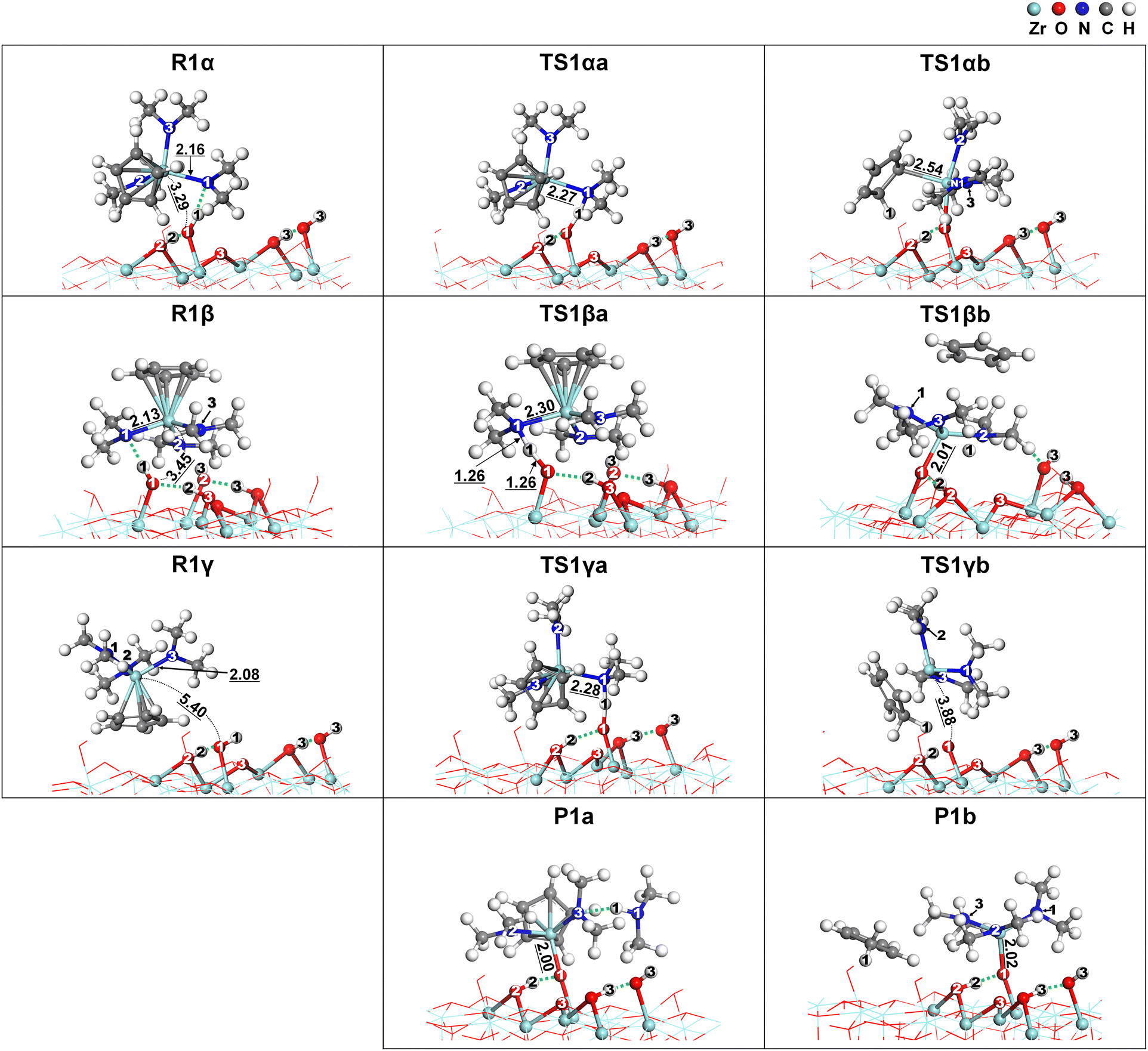
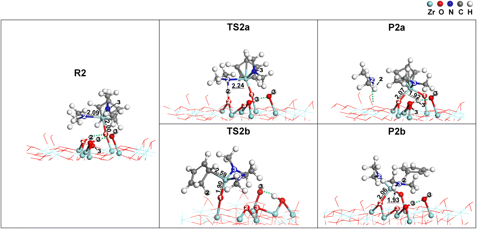
DFT simulations were conducted to investigate the surface reactions of CpZr(NMe2)3 on zirconium oxide. The simulation involved three successive ligand exchange reactions between Cp or NMe2 of CpZr(NMe2)3 and the surface hydroxyl groups of ZrO2. Since CpZr(NMe2)3 is a heteroleptic compound, three different initial orientations of the CpZr(NMe2)3 molecule were considered. In addition, two distinct paths for the release of HNMe2 or HCp as byproducts were considered for each step of the surface reactions. These are illustrated in Fig. 4. Pna and Pnb represent the product states after the nth surface reaction, releasing HNMe2 or HCp, respectively. Rn represents the reactant state for the nth reaction. In R1α, one Cp and two NMe2 ligands face the substrate, while in R1β, three NMe2 ligands face the substrate. In R1γ, only the Cp ligand faces the substrate. R2 and R3 were prepared by removing HNMe2 from P1a and P2a, respectively. Upon the removal of HCp, P1b and P2b become identical to R2 and R3 in our previous publication with Zr(NMe2)4.18 Consequently, the subsequent surface reactions from P1b and P2b are repetitions of the previous publication and were not considered in this paper.
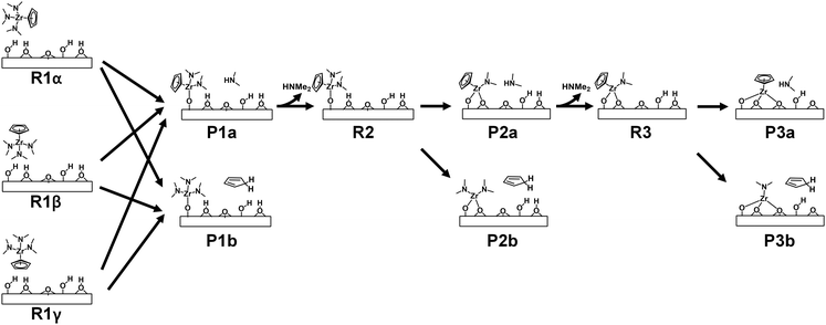 |
| | Fig. 4 Schematic of the multiple paths of surface reactions of CpZr(NMe2)3 on the ZrO2 substrate. | |
Fig. 5 shows the energy diagrams of the first ligand exchange reaction of CpZr(NMe2)3, from UR to P1a or P1bviaR1α, R1β, or R1γ. The adsorption energies of CpZr(NMe2)3 were −1.31 eV, −1.11 eV, and −1.07 eV for R1α, R1β, and R1γ, respectively, indicating that the precursor would adsorb well on ZrO2. The reaction from R1 to P1a, releasing HNMe2, was exothermic, with the reaction energy, ΔE1a, of −0.62 eV to −0.86 eV. The EA1a values, representing the activation energy for three reaction paths from R1 to P1a, were relatively low at 0.22 eV in TS1αa, 0.19 eV in TS1βa, and 0.94 eV in TS1γa. TS1αa, TS1βa, and TS1γa represent the transition states between R1α, R1β, and R1γ and P1a. However, the reaction from R1 to P1b, which releases HCp, was endothermic, with ΔE1b values of 0.10–0.34 eV. The EA1b of the paths from R1 to P1b ranged from 1.66 eV to 3.98 eV. The change in entropy is relatively small because the reaction byproduct remains on the surface. Therefore, P1a paths are favored over P1b paths due to low activation energies. These results also indicate that the activation energies can vary depending on the initial orientation of the CpZr(NMe2)3 molecule.
 |
| | Fig. 5 Energy diagrams for the first reaction of CpZr(NMe2)3 from three reactant states, R1α, R1β, and R1γ, to two product states, (a) P1a and (b) P1b. | |
The energy diagram for the three successive ligand exchange reactions of CpZr(NMe2)3 on the ZrO2 surface is illustrated in Fig. 6. For the first reaction, the paths from the R1α shown in Fig. 5 were employed in Fig. 6 due to the lowest energy values. For all reactions, the pathways releasing HCp were endothermic and exhibited higher EA values than those releasing HNMe2. It can, therefore, be postulated that the surface reactions proceed through the HNMe2-releasing pathways. The desorption processes of HNMe2 from the product states in Fig. 6 were endothermic. However, P1, P2, or P3 would be transformed into R2, R3, and UP at ALD process temperatures because the desorption processes were spontaneous due to the entropy increase at temperatures above 0 °C in the previous study.18
 |
| | Fig. 6 Energy diagrams for the surface reactions of CpZr(NMe2)3 on ZrO2. The Pna states are the product states resulting from the nth surface reaction with the release of HNMe2, while the Pnb states are the product states arising from the release of HCp. | |
Fig. 7 presents the atomistic structural changes during the reaction from R1 to P1. The following equations can describe the two paths for this reaction:
| | | –OH* + CpZr(NMe2)3 → –OZrCp(NMe2)2* + HNMe2 | (6) |
| | | –OH* + CpZr(NMe2)3 → –OZr(NMe2)3* + HCp | (7) |
The formation of
P1a by
eqn (6) was exothermic due to the bond formation of Zr–O1 (5.72 eV) and N–H (3.97 eV), despite the bond dissociation of Zr–N (3.64 eV) and O1–H1 (5.13 eV).
18,32 In contrast, the formation of
P1b by
eqn (7) was endothermic. In comparison to
eqn (6), the Zr–Cp bond (4.29 eV), which is stronger than the Zr–N bond, was dissociated, while the H–Cp bond (3.56 eV), which is weaker than the N–H bond, was newly formed in
eqn (7).
 |
| | Fig. 7 The atomistic structural changes for the paths from three reactant states, R1α, R1β, and R1γ, to two product states, P1a and P1b. The dotted lines indicate hydrogen bonds. Bond lengths are given in Å. | |
In the paths leading to the formation of P1a, the N1–H1 bond was formed without dissociation of any bond in all TS1a states. This resulted in relatively low activation energy values, as shown in Fig. 5, although the Zr–N1 bond was extended. Since the Zr–N1 bond was the shortest at 2.27 Å in TS1αa, the activation energy of the path from R1α was the lowest at 0.22 eV. In contrast, the paths leading to the formation of P1b involve the dissociation of the Cp–Zr bond or the loss of aromaticity of Cp in TS1b states, resulting in relatively high activation energies, as shown in Fig. 5. In TS1αb, the H1 atom was dissociated from O to migrate to Cp and form the H1–Cp bond, which resulted in the loss of aromaticity. The Zr-η1-CpH bond in TS1αb is considerably weaker than the Zr-η5-Cp bond in the R1α states, resulting in an activation energy of 1.66 eV, despite the formation of the Zr–O1 bond. In TS1βb and TS1γb, higher activation energies of 3.98 and 1.95 eV were obtained due to the dissociation of the Cp–Zr bond despite the formation of the Zr–O1 or H1–Cp bond.
Fig. 8 shows the atomistic structural changes for the reaction from R2 to P2. The following equations describe the two paths for this reaction:
| | | –OH* + –OZrCp(NMe2)2* → –O2ZrCp(NMe2)* + HNMe2 | (8) |
| | | –OH* + –OZrCp(NMe2)2* → –O2Zr(NMe2)2* + HCp | (9) |
The formation of
P2a by
eqn (8) was exothermic, while the formation of
P2b by
eqn (9) was endothermic. The exothermicity or endothermicity of
eqn (8) and (9) are comparable to
eqn (6) and (7) because the dissociated or formed bonds are the same in both cases.
 |
| | Fig. 8 The atomistic structural changes for the paths from R2 to two product states, P2a and P2b. The dotted lines indicate hydrogen bonds. Bond lengths are given in Å. | |
The atomistic structure of TS2a was analogous to that of TS1a, with the N2–H2 bond formed and the Zr–N2 bond elongated from 2.09 Å to 2.22 Å, resulting in a low activation energy of 0.16 eV. TS2b, similar to TS1αb, also lost the aromaticity of Cp resulting from the migration of H2 to Cp. However, it showed a relatively high activation energy of 2.26 eV because the Zr–O2 bond was not yet formed.
Fig. 9 shows the atomistic structural changes that occur during the reaction from R3 to P3. Two paths were also assumed as follows:
| | | –OH* + –O2ZrCp(NMe2)* → –O3ZrCp* + HNMe2 | (10) |
| | | –OH* + –O2ZrCp(NMe2)* → –O3Zr(NMe2)* + HCp | (11) |
In
R3, the surface chemical species O
2ZrCp(NMe
2)* has Cp and NMe
2 in opposite directions around the Zr atom, as shown in
Fig. 9. In contrast to the reactions to
P1 or
P2, both paths to
P3 were endothermic, with Δ
E3a of 0.77 eV and Δ
E3b of 1.61 eV. The cleavage of the subsurface O3–Zr bond of both
P3a and
P3b in
Fig. 9 can explain the observed endothermicity.
 |
| | Fig. 9 The atomistic structural changes for the paths from R3 to two product states, P3a and P3b. The dotted lines indicate hydrogen bonds. Bond lengths are given in Å. | |
The activation energy for the path represented by eqn (10), which releases HNMe2, was 0.90 eV, which is higher than those of eqn (6) and (8) in the reactions to P1 and P2. In TS3a, the Zr–O3 and Zr–N3 bonds were elongated, and H3b migrated from −OH3b* to the neighboring −OH3a* to form −OH2*. The activation energy for eqn (11), which releases HCp, was 2.13 eV. In TS3b, the Zr–Cp bond was dissociated, and H3b migrated from −OH3b* to form HCp. The Zr–O3 bond has not yet been formed. Consequently, the reaction to P3 would be energetically unfavorable in contrast to the reactions to P1 and P2.
The above DFT calculations predict that CpZr(NMe2)3 reacts with ZrO2 to form O2ZrCp(NMe2)* surface species, which agrees with the results of the QCM analysis. The surface reaction of CpZr(NMe2)3 is expected to proceed along paths that release two HNMe2 molecules one at a time, while the release of HCp is expected to be unfavorable. Therefore, the surface reactions of CpZr(NMe2)3, a heteroleptic precursor, were similar to those of Zr(NMe2)4, a homoleptic precursor reported in our previous publication.18Table 2 compares the calculated energy values for the surface reaction of Zr(NMe2)4 and CpZr(NMe2)3. For the HNMe2 releasing paths, CpZr(NMe2)3 exhibited similar reaction and activation energy values to those of Zr(NMe2)4. The slight difference in energy values can be explained by the difference in BDE in the two compounds. For example, the EA2 of 0.16 eV for CpZr(NMe2)3 is lower than 0.24 eV for Zr(NMe2)4 due to the lower BDE of the Zr–N bond in CpZr(NMe2)3 compared to that in Zr(NMe2)4. The strong Cp–Zr bond results in a BDE of the Zr–N bond of 3.64 eV in CpZr(NMe2)3, which is lower than the BDE of 3.74 eV for Zr(NMe2)4.
Table 2 Comparison of surface reactions of CpZr(NMe2)3 and Zr(NMe2)4
| Reaction step |
Energy (eV) |
Zr(NMe2)418 |
CpZr(NMe2)3 (this study) |
| HNMe2 release |
HCp release |
| Physisorption |
E
ads
|
−1.16 |
−1.31 |
−1.31 |
| 1st reaction |
ΔE1 |
−0.68 |
−0.62 |
0.34 |
|
E
A1
|
0.19 |
0.22 |
1.66 |
| 2nd reaction |
ΔE2 |
−1.06 |
−0.81 |
0.42 |
|
E
A2
|
0.24 |
0.16 |
2.26 |
| 3rd reaction |
ΔE3 |
0.64 |
0.77 |
1.61 |
|
E
A3
|
0.75 |
0.90 |
2.13 |
Conclusions
The reaction mechanism of ALD ZrO2 using CpZr(NMe2)3 was investigated through the use of in situ QCM and DFT. The QCM analysis yielded a Δf0/Δf1 ratio of 0.64 ± 0.03 at 230 °C, indicating that one Cp ligand and one NMe2 ligand remained on the surface per CpZr(NMe2)3 molecule. A DFT calculation was conducted to simulate the successive ligand exchange reactions between CpZr(NMe2)3 and −OH terminated ZrO2. The paths releasing the first two NMe2 ligands were exothermic, with low activation energy values of 0.22 eV and 0.16 eV. In contrast, the release of the third NMe2 ligand was endothermic and exhibited a high activation energy of 0.90 eV. The paths releasing the Cp ligand were all endothermic and exhibited high activation energies of 1.66–2.26 eV. Consequently, the resulting surface species would be O2ZrCp(NMe2)*, which is consistent with the QCM analysis.
Author contributions
H.-L. Kim: conceptualization, data curation, formal analysis, methodology, project administration, validation, visualization, writing – original draft. O. Kim: data curation, formal analysis, investigation, methodology, validation, visualization, writing – original draft. Yong Richard Sriwijaya: formal analysis, investigation, methodology, visualization. Khabib Khumaini: validation, writing – review & editing. Romel Hidayat: conceptualization, methodology, writing – review & editing. Won-Jun Lee: conceptualization, funding acquisition, project administration, resources, supervision, validation, writing – review & editing.
Data availability
The data supporting this article have been included in the ESI.†
Conflicts of interest
There are no conflicts to declare.
Acknowledgements
This work was supported by the National Research Foundation of Korea (NRF) grant funded by the Korean government (MSIT) (2022R1A2C1005890). This research was also partly supported by the Korea Basic Science Institute (National Research Facilities and Equipment Center) grant funded by the Ministry of Education (2022R1A6C101A774).
Notes and references
- R. Katamreddy, Z. Wang, V. Omarjee, P. V. Rao, C. Dussarrat and N. Blasco, ECS Trans., 2009, 25, 217–230 CrossRef CAS.
- T. Blanquart, J. Niinistö, M. Gavagnin, V. Longo, V. R. Pallem, C. Dussarrat, M. Ritala and M. Leskelä, Chem. Mater., 2012, 24, 3420–3424 CrossRef CAS.
- K. Xu, A. P. Milanov, H. Parala, C. Wenger, C. Baristiran-Kaynak, K. Lakribssi, T. Toader, C. Bock, D. Rogfrealla, H. W. Becker, U. Kunze and A. Devi, Chem. Vap. Deposition, 2012, 18, 27–35 CrossRef CAS.
- M. Kaipio, T. Blanquart, M. Banerjee, K. Xu, J. Niinistö, V. Longo, K. Mizohata, A. Devi, M. Ritala and M. Leskelä, Chem. Vap. Deposition, 2014, 20, 209–216 CrossRef CAS.
- S. C. Buttera, P. Rouf, P. Deminskyi, N. J. O’Brien, H. Pedersen and S. T. Barry, Inorg. Chem., 2021, 60, 11025–11031 CrossRef CAS.
- J.-H. Baek, W.-H. Choi, H. Kim, S. Cheon, Y. Byun, W. Jeon and J.-S. Park, Ceram. Int., 2021, 47, 29030–29035 CrossRef CAS.
- H. Choi, C. Park, S. K. Lee, J. Y. Ryu, S. U. Son, T. Eom and T.-M. Chung, ACS Omega, 2023, 8, 43759–43770 CrossRef CAS PubMed.
- J. Niinistö, K. Kukli, M. Kariniemi, M. Ritala, M. Leskelä, N. Blasco, A. Pinchart, C. Lachaud, N. Laaroussi, Z. Wang and C. Dussarrat, J. Mater. Chem., 2008, 18, 5243–5247 RSC.
- J. Niinistö, T. Blanquart, S. Seppälä, M. Ritala and M. Leskelä, ECS Trans., 2014, 64, 221–232 CrossRef.
- T. Blanquart, J. Niinistö, M. Ritala and M. Leskelä, Chem. Vap. Deposition, 2014, 20, 189–208 CrossRef CAS.
- S. Kim, R. Hidayat, H. Roh, J. Kim, H.-L. Kim, K. Khumaini, M. Park, J.-H. Seok, J. W. Park and W.-J. Lee, J. Mater. Chem. C, 2022, 10, 6696–6709 RSC.
- L. Aarik, H. Alles, A. Aidla, T. Kahro, K. Kukli, J. Niinistö, H. Mändar, A. Tamm, R. Rammula, V. Sammelselg and J. Aarik, Thin Solid Films, 2014, 565, 37–44 CrossRef CAS.
- J.-S. Jung, S.-K. Lee, C.-S. Hong, J.-H. Shin, J.-M. Kim and J.-G. Kang, Thin Solid Films, 2015, 589, 831–837 CrossRef CAS.
- T. T. Van Ngoc, D. Jang, E. Jung, H. Noh, J. Moon, D.-S. Kil, S.-W. Chung and B. Shong, J. Phys. Chem. C, 2022, 126, 18090–18099 CrossRef.
- A. R. Choi, S. Seo, S. Kim, D. Kim, S.-W. Ryu, W.-J. Lee and I.-K. Oh, Appl. Surf. Sci., 2023, 624, 157104 CrossRef CAS.
- X. Liu, S. Ramanathan, A. Longdergan, A. Srivastava, E. Lee, T. E. Seidel, J. T. Barton, D. Pang and R. G. Gordon, J. Electrochem. Soc., 2005, 152, G213 CrossRef CAS.
- S. M. George, Chem. Rev., 2010, 110, 111 CrossRef CAS.
- R. Hidayat, H.-L. Kim, Y. R. Sriwijaya, K. Khumaini and W.-J. Lee, Surf. Interfaces, 2024, 50, 104480 CrossRef CAS.
- M. N. Rocklein and S. M. George, Anal. Chem., 2003, 75, 4975–4982 CrossRef CAS.
- G. Sauerbrey, Verwendung von Schwingquarzen zur Wagung dunner Schichten und zur Mikrowagung, Z. Phys., 1959, 155, 206–222 CrossRef CAS.
- K. Khumaini, H. Roh, H. Han, H.-L. Kim, H. S. Kim, J.-H. Seok, J. W. Park and W.-J. Lee, Appl. Surf. Sci., 2023, 615, 156340 CrossRef CAS.
- B. Delley, J. Chem. Phys., 1990, 92, 508–517 CrossRef CAS.
- B. Delley, J. Chem. Phys., 2000, 113, 7756–7764 CrossRef CAS.
- J. P. Perdew, K. Burke and M. Ernzerhof, Phys. Rev. Lett., 1996, 77, 3865 CrossRef CAS PubMed.
- B. Delley, Phys. Rev. B: Condens. Matter Mater. Phys., 2002, 66, 1–9 CrossRef.
- S. Grimme, J. Comput. Chem., 2006, 27, 1787–1799 CrossRef CAS PubMed.
- E. R. McNellis, J. Meyer and K. Reuter, Phys. Rev. B: Condens. Matter Mater. Phys., 2009, 80, 205414 CrossRef.
- N. Govind, M. Petersen, G. Fitzgerald, D. King-Smith and J. Andzelm, Comput. Mater. Sci., 2003, 28, 250–258 CrossRef CAS.
- K. Khumaini, R. Hidayat, T. R. Mayangsari, T. Chowdhury, H.-L. Kim, S.-I. Lee and W.-J. Lee, Appl. Surf. Sci., 2002, 585, 152750 CrossRef.
- D. Ceresoli and D. Vanderbilt, Phys. Rev. B: Condens. Matter Mater. Phys., 2006, 74, 125108 CrossRef.
- R. Matero, A. Rahtu and M. Ritala, Chem. Mater., 2001, 13, 4506–4511 CrossRef CAS.
- Y. Choi, H. Son, K. Khumaini, H. Han, H. Roh, H.-L. Kim, S.-I. Lee and W.-J. Lee, J. Mater. Chem. C, 2022, 10, 17377–17385 RSC.
Footnotes |
| † Electronic supplementary information (ESI) available. See DOI: https://doi.org/10.1039/d4ma00966e |
| ‡ H.-L. Kim and O. Kim are equally contributing first authors. |
|
| This journal is © The Royal Society of Chemistry 2025 |
Click here to see how this site uses Cookies. View our privacy policy here. 
 Open Access Article
 This Open Access Article is licensed under a Creative Commons Attribution-Non Commercial 3.0 Unported Licence
 ab,
Okhyeon
Kim‡
ab,
Okhyeon
Kim‡