DOI:
10.1039/D4MA00923A
(Paper)
Mater. Adv., 2025,
6, 726-742
Low-temperature synthesis of oval-shaped CoWO4 nanomaterials for enhanced asymmetric supercapacitor performance†
Received
12th September 2024
, Accepted 4th December 2024
First published on 5th December 2024
Abstract
The electrochemical supercapacitor has been shown to be a reliable and innovative type of energy storage technology over the years. Recent research has shown that CoWO4 is a potential material for supercapacitor applications because of its unique characteristics, which make it suitable for energy storage. CoWO4 nanostructures are synthesized using a low-temperature hydrothermal method followed by calcination at 300 °C for 2 h. The powder was characterized through XRD with Rietveld refinement, FE-SEM, TEM, Raman spectroscopy, FTIR, XPS, BET and electrochemical techniques. XRD analysis revealed a monoclinic crystal framework of CoWO4 with a space group of P2/c. FE-SEM and TEM results are in good agreement with each other and reveal elongated oval-shaped nanostructures of CoWO4. BET analysis indicates the mesoporosity in the nanostructures, which helps in the increased active sites for an efficient supercapacitor application. XPS results confirm the presence of a Co2+ oxidation state in the CoWO4 nanostructure. The electrochemical characterizations were carried out using a three-electrode system. The CoWO4 electrode indicates a high specific capacitance of 235 F g−1 at 10 mV s−1 in 6 M KOH electrolyte between −0.15 V to 0.45 V potential window and retains 93.25% capacitance even after 10![[thin space (1/6-em)]](https://www.rsc.org/images/entities/char_2009.gif) 000 cycles. Additionally, an asymmetric supercapacitor is assembled using the CoWO4 and activated carbon as the positive and negative electrodes, respectively, achieving a maximum energy density of 51.8 W h kg−1 and an excellent capacity retention of 96.43% after 10000 cycles at 3 A g−1. This work will be helpful in the development of high-capacitive, durable, and safe supercapacitor devices for future energy needs.
000 cycles. Additionally, an asymmetric supercapacitor is assembled using the CoWO4 and activated carbon as the positive and negative electrodes, respectively, achieving a maximum energy density of 51.8 W h kg−1 and an excellent capacity retention of 96.43% after 10000 cycles at 3 A g−1. This work will be helpful in the development of high-capacitive, durable, and safe supercapacitor devices for future energy needs.
1. Introduction
The rapid depletion of fossil fuels has harmed both the environment and humans. Clean and sustainable alternatives must be created to produce energy on a large scale and at a low cost. In this context, electrochemical devices such as batteries, fuel cells, and capacitors will be effective in mitigating the consequences of environmental deterioration and the shortage of fossil fuels. Among these electrochemical storage devices, supercapacitors stand out as emerging energy storage technologies due to their high-power density, long life cycle, low weight, low cost, and environmental friendliness. Supercapacitors have been proposed as potential replacements for lithium-ion batteries and fuel cells in many fields, including uninterruptible power supplies, portable electronic devices, and hybrid electric vehicles. Additionally, electrochemical supercapacitors have a higher energy density than conventional capacitors and supply power at a higher pace than secondary batteries and fuel cells. However, their lackluster energy density has constrained their development for large-scale production.1
For the development of high-performance electrode materials for supercapacitors, a variety of electrode materials, including carbon-based materials, metal sulfides, transition metal oxides/hydroxides, and conductive polymers, have been researched by numerous researchers.2–5 Among various materials, binary metal oxides or mixed metal oxides, especially tungsten-based transition metals (AWO4), have received special attention because of their integration of several valence states of W atoms, which provides exceptional physical and chemical capabilities.6 The family of tungsten AWO4 inorganic materials can be divided into two groups: scheelite (A = Ca, Sr, Ba, and Pb)7 and wolframite (A = Cd, Co, Mn, Zn, and Cu).8 Among these metal tungstates, cobalt tungstate (CoWO4) with a monoclinic wolframite structure has been used in a wide range of potential applications including high-density supercapacitors,9 photocatalysts,10 a catalyst for the oxygen evolution reaction16 (OER) and hydrogen production,11 microwave dielectric ceramics,12 photovoltaic electrochemical cells,13 and solid electrolyte galvanic cells.14 According to the literature, He et al.15 prepared NiWO4 and CoWO4 nanostructures via a one-step hydrothermal approach and demonstrated high specific capacitance of 797.8 F g−1 and 764.4 F g−1 respectively. Heytor et al.16 proposed an innovative and creative green sol–gel synthesis technique, followed by calcination at 800 °C for 2 hours in air, for the synthesis of CoWO4 using agar–agar from red seaweed (Rhodophyta). The as-prepared powder exhibits battery-type behavior, with a maximum specific capacity of 77 C g−1 at a specific current of 1 A g−1 and an electrode capacity of around 98% maintained across 1000 charge–discharge cycles at 1 A g−1. Xing et al.17 employed wet chemical and hydrothermal processes to produce amorphous and crystalline CoWO4 powder for supercapacitor electrode materials. At a current density of 0.5 A g−1, the electrodes of CoWO4-amorphous and CoWO4-crystalline displayed specific capacitances of 403 F g−1 and 264 F g−1, respectively. In another approach, Chu et al.18 used ZIF-67 to create a flower-like 3D hollow CoWO4 structure on nickel foam for high-performance asymmetrical supercapacitors. The as-prepared hollow structure on nickel foam has a good specific capacitance of 1395 F g−1, and outstanding cycling stability of 89.00% after 3000 cycles with better rate properties. Similarly, Chen et al.1 prepared an asymmetric supercapacitor by growing a nanosheet array of CoWO4 on nickel foam. The binder-free nanosheet array has an impressive cycling performance with a high specific capacitance of 1127.6 F g−1 at 1 A g−1 and excellent capacitance retention of 92.4% after 3000 cycles. The asymmetric device also delivers a maximum energy density of 48 W h kg−1 at a power density of 365 W kg−1. Oliveira et al.19 developed a CoWO4 nanocrystal by using co-precipitation (CP) and a polymeric precursor (PP) method followed by calcination at 800 °C for 4 h for the study of colorimetric and supercapacitor electrode characteristics. Based on their findings, they determined that the prepared nanocrystal functions as both a pigment and capacitor. At 40 mV s−1 and 5 mV s−1, the specific capacitance measurements of CoWO4 crystals as electrodes CP and PP were 192.5 F g−1 and 249.1 F g−1, respectively. Patil et al.20 recently developed a CoWO4 nanostructure for supercapacitor applications using a hydrothermal technique followed by 4 hours of calcination at 800 °C. The nanostructure CoWO4 electrode material had a specific capacitance of 712 F g−1 at a current density of 5 mA cm−2. After 5000 charge–discharge cycles, the electrode retained 84.2% of its original capacity. The as-prepared electrode remained stable after 5000 charge–discharge cycles, retaining 84.2% of its initial capacity.
According to the literature, the conventional procedures employed for synthesizing CoWO4 typically involve high-temperature calcination with extensive processing time. Despite the potential of CoWO4 for energy storage devices, very few studies have concentrated on the synthesis of low-temperature CoWO4 powder. At the same time, the evaluation of the electrochemical characteristics for pure CoWO4 without any composite material is also limited. Thus, the current study focuses on developing low-temperature hydrothermal synthesis for CoWO4. Furthermore, a detailed analysis of pure CoWO4 has been demonstrated for its asymmetric supercapacitor application.
2. Experimental
2.1. Synthesis
In a typical synthesis, 0.1 mol of CoNO3.6H2O was dissolved in 15 ml of distilled water and stirred at room temperature. Then, 10 mL of distilled water containing 0.1 mol of Na2WO4.4H2O was added dropwise, and the resulting suspension was transferred into a Teflon-lined stainless autoclave. The autoclave was sealed and maintained at 100 °C for 4 h, and then it was allowed to cool to room temperature. The precipitate was centrifuged, washed with excess distilled water and acetone alternately, and finally dried at 60 °C. The as such dry powder was further calcinated at 300 °C for 2 h to yield a crystalline powder of CoWO4. All chemicals were directly used, and supplied by Merck Limited, India.
2.2. Characterization
The composition of the powder was determined by an X-ray diffractometer (Bruker, D2 PHASER) having Ni-filtered CuKα radiation (λ = 1.5418 Å) and operated in the 2θ range from 10 to 70°. Field emission scanning electron microscopy (FE-SEM) (JEOL model-JSM7100F) was used to investigate the morphology of the CoWO4 powder. Transmission electron microscopy (TEM) measurements were performed on the JEOL, JEM 2100 instrument, and energy dispersive X-ray spectroscopy (EDX) was used to analyze a qualitative elemental analysis. Raman spectroscopy was performed using a M/s Renishaw inVia spectrometer, 514 nm (Ar ion) and 785 nm (diode laser). Fourier-transform infrared spectroscopy (FTIR) analysis was performed using a SHIMADZU IRSpirit-X spectrometer in the wavenumber range of 400 cm−1 to 4000 cm−1. Brunauer–Emmett–Teller (BET) analysis was performed using BELSORP MAX 11 Ver.2.0.4 version. X-ray photoelectron spectroscopy (XPS) characterization was performed on the ESCA spectrometer. The electrochemical analysis of the synthesized CoWO4 was conducted using the CHI6002E workstation manufactured by CH Instruments. The electrode preparation method involves the blending of CoWO4 as an active material, carbon black as a conductive agent, and polyvinylidene fluoride (PVDF) as a binder in an 8.0:1.5:0.5 ratio. Using a mortar pestle, these components were combined with a few drops of N-methyl-2-pyrrolidone (NMP) solvent to make a slurry. This mixture was then applied carefully on a clean carbon cloth. Following that, the material was subjected to a drying period of 4 h at 100 °C to ensure the absence of NMP solvent and strong adhesion. Approximately 4 mg of active material was loaded on carbon cloth, covering a surface area of 1 × 1 cm2. The charge storage was examined using a three-electrode system within a 6 M potassium hydroxide (KOH) electrolyte solution. In this setup, an Ag/AgCl electrode served as the reference, while a platinum (Pt) wire acted as the counter electrode and cyclic voltammetry (CV) was carried out between −0.15 to 0.45 V at scan rates ranging from 10 to 100 mV s−1. Galvanostatic charge–discharge (GCD) was carried out at currents ranging from 0.5 to 3.5 A g−1 in a potential window of −0.5 to 0.45 V. The electrochemical stability of the CoWO4 electrode was tested over 10000 charge–discharge cycles at 1 A g−1. Electrochemical impedance spectroscopy (EIS) of the CoWO4 electrode was analyzed at the frequency range 0.1 Hz to 1 MHz and AC amplitude 5 mV was applied. Furthermore, an asymmetric device is fabricated and the electrochemical stability was tested over 10000 charge–discharge cycles at 3 A g−1 followed by EIS at a frequency ranging from 0.1 Hz to 1 M Hz.
2.3. Fabrication of the device
To determine the effective use of the CoWO4 electrode, an efficient asymmetric supercapacitor is fabricated by pairing CoWO4 and activated carbon (AC) as the cathode and anode, respectively.
The charges on the two electrodes were equalized using the charge balance principle as stated by eqn (1), where Q+ and Q− represent the charges on the positive and negative electrodes, respectively.21
3. Results and discussion
3.1. X-ray diffraction
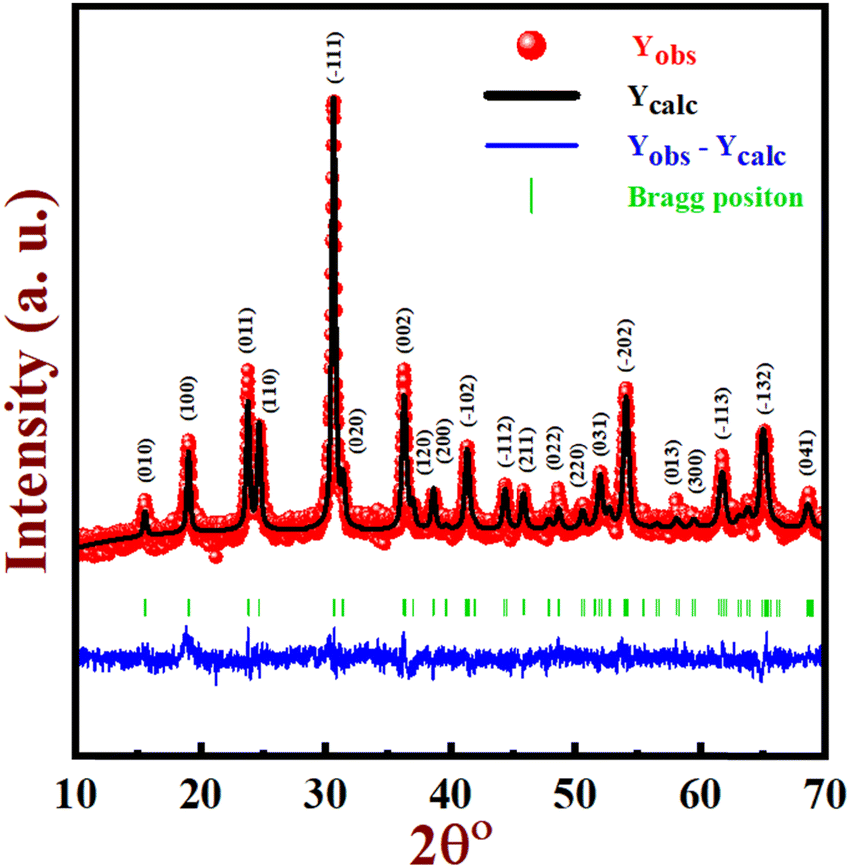
Fig. 1 depicts the XRD pattern and Rietveld refinement of CoWO4 synthesized by the hydrothermal technique. The XRD peaks have been indexed using a monoclinic crystal framework with a space group of P2/c.22 The prepared sample lattice parameters are a = 4.6616 Å, b = 5.6972 Å, and c = 4.9572 Å while α = β = γ = 90°, which match well with the JCPDS 15-0867 (vertical green line). The diffraction peaks at 15.5°, 18.9°, 23.8°, 24.6°, 30.6°, 31.4°, 36.2°, 36.9°, 38.5°, 41.2°, 44.3°, 45.7°, 48.7°, 50.5°, 51.5°, 53.9°, 58.1°, 59.3°, 61.7°, 65°, and 68.6° have reflection planes at (0 1 0), (1 0 0), (0 1 1), (1 1 0), (−1 1 1), (0 2 0), (0 0 2), (1 2 0), (2 0 0), (−1 0 2), (−1 1 2), (2 1 1), (0 2 2), (2 2 0), (0 3 1), (−2 0 2), (0 1 3), (3 0 0), (−1 1 3), (−1 3 2), and (0 4 1), respectively.23 Additionally, the data presented did not seem to exhibit any additional peaks, suggesting the absence of any impurities.
 |
| | Fig. 1 Powder XRD pattern and Rietveld refinement of CoWO4. | |
Rietveld refinement was carried out using the FullProf package on the XRD data of CoWO4, and the crystallographic information file (CIF) for the same is provided in the ESI.† The pseudo-Voigt function and linear interpolation between the background points with adjustable height were employed in the refinement to establish the profile shape and background, respectively. All other parameters, such as scale factor, zero correction, background, mixing parameters, lattice parameters, and positional coordinates, were varied during the process of refinement. The χ2 and (goodness of fit) GOF index from the Rietveld refinement study are 1.45 and 1.2, respectively. The observed pattern (red) perfectly fits with the experimental data (black), and the difference between observed and calculated (blue) is attempted to be reduced, as illustrated in Fig. 1, and the crystallographic atomic parameters are shown in Table 1.
Table 1 Rietveld refinement data of CoWO4
| Atom |
Wyckoff site |
x
|
y
|
z
|
Occupancy |
Multiplicity |
| Co |
2f |
0.50000 |
0.65239 |
0.25000 |
0.540 |
2 |
| W |
2e |
0 |
0.17772 |
0.25000 |
0.565 |
2 |
| O1 |
4g |
0.30739 |
0.13306 |
0.87660 |
1.252 |
4 |
| O2 |
4g |
0.27618 |
0.36776 |
0.35770 |
1.304 |
4 |
The structure of CoWO4 was constructed by utilizing the data provided in Table 1. VESTA software, renowned for its precision in molecular visualization, was employed in this construction process. This software enabled a detailed and accurate representation of the CoWO4 structure, ensuring a comprehensive understanding of its composition. Based on the available information, the structure of CoWO4 can be characterized as a distorted arrangement of oxygen atoms forming a hexagonal shape. Within this arrangement, both cobalt (Co) and tungsten (W) are bonded to six oxygen atoms indicating a 6-fold coordination with the oxygen. The CoO6 and WO6 octahedral units connect with neighbouring polyhedra of the same kind through two edges.24 This connection results in the creation of continuous chains consisting of similar octahedrons along the [0 0 1] axis, as depicted in Fig. 2a and b.
 |
| | Fig. 2 (a) An illustration of CoWO4 showing the octahedral structure of CoO6 and WO6 as represented by the spheres of cobalt (blue), tungsten (yellow), and oxygen (red). (b) The CoWO4 unit cell is projected onto the (0 1 0) plane, revealing the alternate networks of the WO6 and CoO6 octahedron towards the [0 0 1] direction. | |
3.2. Raman spectroscopy
Raman spectroscopy of CoWO4 nanostructures is shown in Fig. 3. The vibrations of W![[double bond, length as m-dash]](https://www.rsc.org/images/entities/char_e001.gif) O bonds are attributed by bands at 885 cm−1 and 768 cm−1, which are identified as strong symmetric stretching and weak asymmetric stretching respectively. The stretching of O–W–O bonds in the (W2O4)n polymeric chain is attributed to weak symmetric and asymmetric bands at 540 cm−1 and 689 cm−1, respectively. The vibration band at 408 cm−1 is attributed to in-plane deformation of terminal W–O bonds while the rotation of the bridging W–O bond is specified at 340 cm−1. The vibration band at 209 cm−1 and 275 cm−1 is attributed to stretching and out-of-plane vibration of the Co–O bond.23
O bonds are attributed by bands at 885 cm−1 and 768 cm−1, which are identified as strong symmetric stretching and weak asymmetric stretching respectively. The stretching of O–W–O bonds in the (W2O4)n polymeric chain is attributed to weak symmetric and asymmetric bands at 540 cm−1 and 689 cm−1, respectively. The vibration band at 408 cm−1 is attributed to in-plane deformation of terminal W–O bonds while the rotation of the bridging W–O bond is specified at 340 cm−1. The vibration band at 209 cm−1 and 275 cm−1 is attributed to stretching and out-of-plane vibration of the Co–O bond.23
 |
| | Fig. 3 Raman spectroscopy of CoWO4 nanostructures. | |
3.3. FTIR spectroscopy
As depicted in Fig. 4, the FTIR spectrum is acquired within the wavenumber range of 400 cm−1 to 4000 cm−1. The stretching vibration of W–O–W bridging bonds is validated by the absorption peak at 860 cm−1.25 The absorption peaks at 680 cm−1 and 579 cm−1 are attributed to the symmetric vibration of the O atom in the Co–O–W bridging bond. The presence of the absorption band at 526 cm−1 corresponds to the stretching mode of W - W bonds, as well as the asymmetric stretching vibration for the WO6 octahedron. The asymmetrical deformation of Co–O in the CoO6 octahedron corresponds to the absorption band at 466 cm−1.26,27 Hence, FTIR analysis validates the formation of CoWO4, consistent with both the XRD pattern and Raman analysis. The FTIR analysis confirmed the existence of moisture content in the CoWO4 sample; this may be due to absorbed water molecules on the sample's surface in environmental conditions.28 The presence of peaks at 3421 cm−1 and 1622 cm−1 is attributed to the bending and stretching vibrations of H–O–H and O–H in water molecules.29
 |
| | Fig. 4 FTIR spectrum of CoWO4 nanostructures. | |
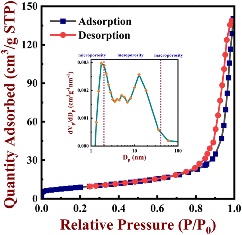
3.4. BET analysis
The surface area, volume, and pore-size distribution of the CoWO4 nanostructures were evaluated using the BET method. Fig. 5 illustrates the nitrogen adsorption–desorption isotherm at 77 K and the inset relates to the pore size distribution curve (BJH curve) of CoWO4. The BET isotherm was identified as a type 4 isotherm featuring H2-type hysteresis, which supports the existence of mesoporous structures.30 As shown in the inset, the BJH curve also shows a clear distribution in the mesoporous region (2–50 nm). Additionally, the surface area, average pore diameter, and pore volume were determined to be 32.595 m2 g−1 29.525 nm, and 0.2062 cm3 g−1, respectively. The investigation suggests that the generated nanostructures have excellent porosity, which is one of the essential components of an effective supercapacitor.
 |
| | Fig. 5 The gas adsorption–desorption isotherm curve of CoWO4 and inset shows the BJH plot for the porosity evolution of CoWO4. | |
3.5. FE-SEM, TEM, and EDS analysis
The FE-SEM images of the CoWO4 nanostructures showcase surface morphologies at various magnification scales, as illustrated in Fig. 6a–c. In Fig. 6a, the structures appear agglomerated, displaying indistinct needle or spike-like features on their surface. Fig. 6b reveals an irregular surface pattern surrounded by more pronounced needle or spike-like protrusions, varying in size – some are elongated, while others are smaller and less sharply pointed. In Fig. 6c, clearer spike-like formations can be observed within the nanostructures, hinting at a potential flower-like arrangement. The surface characteristics captured in the FE-SEM images closely mirror the mesoporous attributes as revealed by BET measurements. This structural porosity likely influences the diverse surface features observed in the FE-SEM images.
 |
| | Fig. 6 FE-SEM image of CoWO4: (a) clustering structures exhibiting indeterminate spike-like formations. (b) An irregular surface pattern bound by well-defined needle or spike-like projections of varied sizes. (c) More defined spikes within the nanostructures indicate a formation similar to that of a flower. (d) and (e) TEM images showing elongated oval structures and insets showing the statistical Gaussian distribution profile revealing an average CoWO4 particle size of 16.71 × 6.83 nm (length × width). | |
TEM images in Fig. 6d and e showcase the morphology of the synthesized CoWO4 nanostructures. These appear as elongated, flaky, oval-like structures with average dimensions of approximately 16.71 nm for the length and 6.83 nm for the width, as shown in the inset of Fig. 6e. Interestingly, the overall shapes of these structures align well with the spike-like features observed in the corresponding SEM images (Fig. 6a–c). This remarkable concordance suggests that the elongated ovals observed in TEM might be the underlying structural element responsible for the emergence of the spike-like features identified via FE-SEM.
The simultaneous FE-SEM elemental mapping studies of the corresponding quantified areas (Fig. 7a–e) reveal the presence of oxygen (O, yellow in Fig. 7b), tungsten (red in Fig. 7c), and cobalt (Co, blue in Fig. 6d) elements in the CoWO4 nanostructures. The energy dispersive X-ray (EDX) spectrum also shows a clear indication of the presence of the elements like cobalt, tungsten, and oxygen without any additional elements (Fig. 7e). Using the acquired quantitative EDX, the cobalt, tungsten, and oxygen atomic percentages are recorded to be 29.22%, 15.65%, and 55.13%, respectively.
 |
| | Fig. 7 (a) Simultaneous elemental mapping image, which confirmed the presence of (b) oxygen; (c) tungsten; (d) cobalt, and (e) the EDX spectrum of CoWO4. | |
3.6. XPS analysis
XPS was utilized to investigate the binding energy and chemical makeup of the surface atoms in the CoWO4 nanostructures. The XPS spectra of the CoWO4 nanostructures are illustrated in Fig. 8a–d. The total survey scan of the CoWO4 nanostructures is depicted in Fig. 8a. It displays the distinctive peaks of Co 2p, W 5f, and O 1s, as well as the presence of a C1s line, which may be the result of hydrocarbons that have been absorbed by the surface of the nanostructures. Fig. 8b displays the specific XPS region related to Co 2p, which includes a pair of doublets and additional satellite peaks abbreviated as “Sats.”. A distinct peak at 780.7 eV is attributed to Co 2p3/2, accompanied by a wider satellite peak detected at 786.9 eV. Additionally, a prominent peak at 797.1 eV signifies Co 2p1/2, along with its satellite peak at 803.3 eV. Significantly, the presence of these additional satellite peaks alongside the primary ones is a distinctive feature linked to the Co2+ oxidation state.31 XPS analysis revealed distinct oxygen peaks at 529.8 and 531.2 eV as seen in Fig. 8c, indicating different oxygen configurations. The lower binding energy peak at 529.8 eV suggests adsorbed oxygen, likely influenced by the incorporation of excess oxygen during calcination in air. Conversely, the higher energy peak at 531.2 eV indicates the presence of atomic or valence oxygen within the compound.32 Additionally, the W4f core-level spectrum (Fig. 8d) displays spin doublets, W 4f5/2 at 37.3 eV and W 4f7/2 at 35.3 eV, corresponding to the tungsten valence state of +6.11
 |
| | Fig. 8 (a) Comprehensive XPS survey scan, (b) Co 2p core level, (c) O 1s core level and (d) W 4f core level scan of the as-synthesized CoWO4 powder. | |
3.7. Electrochemical analysis
The specific capacitance (Cs) of the CoWO4 electrode material was recorded using the CV curves and its equation is given by,| |  | (2) |
where “Cs” (F g−1) denotes specific capacitance, “ ” indicate the integral area of the CV curve, and “S” denotes scan rate. The parameter “m” represents the quantity of active mass loaded on the working electrode, while “ΔV” denotes the potential range of the electrode material.9
The outcomes of the CV curves at scan rates ranging from 10 to 100 mV s−1 within a voltage window of −0.15 to 0.45 V are shown in Fig. 9a. The exhibited quasi-rectangular shape of the CV curves signifies the pseudocapacitive behaviour of the synthesized sample. Moreover, it's evident that as the scan rate increases, the current below the curves also increases, indicating a direct proportionality between the voltammetric current and the scan rate.33 The shape of the redox peaks remained constant even as the scan rate was increased, this implies that precise and rapid reversible redox reactions are taking place at the interface between the electrolyte and the electrode material. The redox reaction mechanism can be linked to the valence state between Co2+ and Co3+, while the related [WO4]2− ions are reduced to [WO4]3−. When the CoWO4 electrode is exposed to a KOH electrolyte, the following redox process occurs within it (W does not take part in faradaic reactions):34
| | | Co2+ + OH− ↔ CoOOH + H2O + e− | (3) |
| | | CoOOH + OH− ↔ CoO2 + H2O + e− | (4) |
 |
| | Fig. 9 (a) CV patterns for the CoWO4 electrode. (b) Graph depicting the correlation between specific capacitance and the scan rate of the CoWO4 electrode. (c) Galvanostatic charge–discharge profile of the CoWO4 electrode. (d) Specific capacity of the CoWO4 electrode at different current densities. (e) Power density vs. energy density (Ragone plot) of the CoWO4 electrode. (f) Electrochemical impedance spectroscopy (EIS) Nyquist plot. (g) Performance of the GCD life cycle with current density 1 A g−1 of the CoWO4 electrode material. | |
Fig. 9b shows how the Cs of the CoWO4 electrode varies with different scan rates. The Cs of the CoWO4 electrodes decreases from 235 F g−1 to 186 F g−1 with a scan rate from 10 mV s−1 to 100 mV s−1.
Using galvanostatic measurements, the discharge patterns under varying current densities for the CoWO4 electrode are shown in Fig. 9c. The galvanostatic charge–discharge revealed asymmetrical charging and discharging curves, indicating the pseudo-capacitive behaviour of the CoWO4 nanostructures, which aligns well with the corresponding CV plots. The Cs of the CoWO4 electrode material was measured using the GCD curves and its equation is given by,35
| |  | (5) |
where
Im = current density (A g
−1), Δ
t = discharge time (s), and Δ
V = potential drop (V).
Fig. 9d displays the specific capacity versus current density plot for CoWO4 nanostructures, and it illustrates the range of current density, from 0.5 A g−1 to 3.0 A g−1, within the voltage window of −0.15 to 0.45 V. The specific capacitance was noted to be 138 F g−1 at a current density of 1 A g−1. Furthermore, as the applied current density increases, there is a corresponding decrease in the specific capacity of the electrode material. With rising current densities, the charging and discharging processes speed up, limiting the time for ions to interact effectively with the electrode substance. This reduction in interaction time diminishes the material's overall charge storage potential and may elevate resistive losses, consequently reducing its specific capacity.
Fig. 9e displays the Ragone plot (power density vs. energy density) of a CoWO4 electrode. The charge/discharge curves at different current densities were used to determine the energy and power densities; they can be obtained using the following formulas.36
| |  | (6) |
| |  | (7) |
where
E = energy density (W h kg
−1),
P = power density (W kg
−1),
C = specific capacity (F g
−1),
Q = total charge delivered (C), Δ
V = potential window (V),
t = discharge time (s).
From Fig. 9e, it is evident that energy density decreases with the increase in power density. At a power density of 150 W kg−1, the energy density was 6.93 W h kg−1. When the power density was increased to 900 W kg−1, energy density was recorded as 6.8 W h kg−1.
The electrochemical impedance data of the CoWO4 nanostructures are displayed in the Nyquist plot in Fig. 9f. The corresponding circuit is shown in the inset. In the high-frequency region, the initial point in the real axis (Z′) on the Nyquist plot suggests the series resistance (Rs) of the electrode, which is due to the combined effect of internal resistance of the electrode, ionic resistance of the electrolyte, and contact resistance of the current collector and electrode.37 In the EIS figure, the Rs value of 6.9 Ω indicates the minimum internal resistance and excellent electrical contact of the electrode. A semi-circle observed in the plot provides information regarding the charge-transfer resistance (Rct) and double-layer capacitance (CDL) parallel to the electrode/electrolyte interface. The obtained values of Rct and CDL are 11.35 Ω and 0.001795 F, respectively, which indicates good electronic conductivity, a fast charge transport rate for ions, and the semi-conducting nature of the CoWO4 material. In the low-frequency region, the slope of the straight line suggests the Warburg impedance (w) component. The nearly linear line and high slope value of the line result in ion diffusion in the host material and electrolyte diffusion in the electrode surface.22,38
In addition, the electrode material was evaluated for cyclic stability at a current density of 1 A g−1 through 10000 repeated charge–discharge cycles, as depicted in Fig. 9g. The specific capacitance slightly decreases from 138 F g−1 to 133 F g−1 after 5000 cycles, representing a 96.38% retention rate compared to the initial values. Even though the charge–discharge cycle proceeds up to 10000 cycles, the capacitance remains as high as 93.25% without any major capacitance fading, indicating excellent cycling stability of the CoWO4 material in the supercapacitor application.
Furthermore, XRD analysis was conducted on the CoWO4 electrode before and after 10000 cycles, as depicted in S1 (ESI†). There was no significant change observed in the phase of the CoWO4 electrode, indicating that rapid charging/discharging does not result in any structural changes. Table S1 (ESI†) presents a comparison with various previously published procedures for the fabrication of AWO4 electrodes and their corresponding Cs at various scan rates.19,39–49 Our experimental findings demonstrate significantly reduced reaction time coupled with a notably higher number of cycles compared to previous works. It also highlights the electrochemical activity of CoWO4 without adding any composites. This indicates the remarkable efficiency and durability of our approach, showcasing its potential for practical application as a supercapacitor.
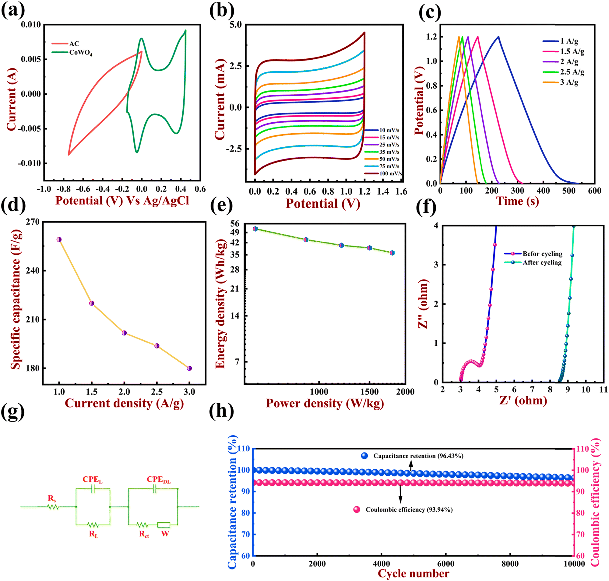
3.8. Electrochemical analysis for an asymmetric supercapacitor device
To examine the practical use of CoWO4 and AC electrodes, an efficient asymmetric device is fabricated by pairing AC and CoWO4 as the cathode and anode, respectively. The device's maximum voltage range is determined collectively by AC and CoWO4 electrodes, as shown in Fig. 10a. Fig. 10b shows the CV curves for the asymmetric device within the voltage range of 0 to 1.2 V at a varying scan rate. It can be observed that the device maintains its initial CV shape as the scan rate varies from 10 mV s−1 to 100 mV s−1. Fig. 10c shows the GCD patterns of the asymmetric device with current densities ranging from 1 A g−1 to 3 A g−1. The specific capacitance of the asymmetric device can be determined based on the GCD curve by utilizing the following equation,| |  | (8) |
where Cs (F g−1) is the specific capacitance of the full cell, I stands for discharge current, Δt stands for discharge time, m is the mass loading of the electrode and ΔV is the discharge voltage.
 |
| | Fig. 10 (a) CV curves of AC and CoWO4 electrodes at 50 mV s−1. (b) CV measurement of the CoWO4‖AC asymmetric device at varying scan rates. (c) GCD curve of the CoWO4‖AC asymmetric device at varying current densities. (d) Specific capacitances for varying current density. (e) Ragone plot of the CoWO4‖AC asymmetric device. (f) Nyquist plot for the 1st and 10000th cycles of the CoWO4‖AC asymmetric device. (g) The Randle's model corresponding circuit where Rs is the equivalent circuit resistance, RL represents leakage resistance, RCt represents electrode–electrolyte resistance, CPEDL is the constant phase element of the double layer, CPEL represents mass capacitance and W represents Warburg element. (h) Capacitance retention (left vs. bottom) and coulombic efficiency (right vs. bottom) at 3 A g−1 current density for 10000 cycles. | |
Fig. 10d displays the specific capacitance versus current density plot for the CoWO4‖AC asymmetric device, from 1 A g−1 to 3 A g−1 within the voltage window of 0 V to 1.2 V. The specific capacitance was noted to be 259 F g−1 at 1 A g−1. Fig. 10e displays the Ragone plot (power density vs. energy density) of a CoWO4‖AC asymmetric device. The GCD curves at different current densities were used to determine the energy and power densities, which were obtained using the following equations,
| |  | (9) |
| |  | (10) |
where
E (W h kg
−1) stands for energy density, and
P (W kg
−1) stands for power density.
From Fig. 10e, it is evident that energy density decreases with the increase in power density. As the power density increases from 600 W kg−1 to 1800 W kg−1, energy density decreases from 51.8 W h kg−1 to 36 W h kg−1.
The electrochemical impedance data of the asymmetric device at the 1st and 10000th cycle are displayed by the Nyquist plot in Fig. 10f. The impedance patterns of the cell display a semi-circle loop in the high-frequency region followed by an arc in the low-frequency region. Fig. 10g represents the equivalent circuit that was used to fit the EIS charts (Fig. 10f). Table 2 displays the fitted data for each circuit element. To examine the change in the internal resistance over 10000 cycles, EIS plots before and after cycling were recorded. The solution resistance or equivalent series resistance is denoted by ‘Rs’ which in general indicates the electrode's internal resistance combined with the resistance of the electrolyte.50 It was observed that the Rs of the cell increased from 3.02 Ω to 8.5 Ω with the increase in cycle number from 1 to 10000. This confirms that capacity decreases over an extended charge–discharge cycle as a natural outcome of increased resistance.51RCt or charge transfer resistance, is a measurement of how rapidly redox reactions occur at the electrode–electrolyte interface. Low RCt indicates rapid movement of ions inside the device, which in turn decreases the effective capacitance.52 The constant phase element (CPE) known as CPEDL stands for double-layer capacitance. The term double layer refers to the separation of ionic charges, which occur at the interfaces between the solid electrode and ionic solution. At this stage, a capacitance arises and is known as double-layer capacitance because the accumulation of opposite charges occurs across such interfaces. With the increase in cycling, CPEDL increases, which typically degrades the overall efficiency of the device.53 The Warburg element ‘W’ is the outcome of the frequency dependence of the ion diffusion into the porous electrode in the intermediate frequency zone. The term ‘CPEL’ stands for pseudocapacitance, and is a phenomenon that results from voltage-dependent faradaic charge transfer mechanisms. In the CoWO4‖AC asymmetric device, there is no significant difference observed in pseudocapacitance before and after cycling. Leakage resistance ‘RL’ is connected in parallel to CPEL. This can be ignored in the circuit since it is very high.54
Table 2 Corresponding circuit elements of the device before and after cycling
| CoWO4‖AC |
R
S (Ω) |
R
CT (Ω) |
CPEDL |
W
|
CPEL |
| 1st cycle |
3.021 |
0.971 |
0.0000317 |
0.0598 |
0.00248 |
| 10000th cycle |
8.534 |
0.077 |
0.000190 |
0.0852 |
0.00245 |
Galvanostatic charge–discharge at 3 A g−1 was used to evaluate the cycling stability of the CoWO4‖AC device over 10000 cycles, and the results are illustrated in Fig. 10h. The CoWO4‖AC demonstrated excellent cycling stability in 6 M KOH and retained about 96.43% of its initial capacitance. Additionally, it has high coulombic efficiency of about 93.94% over 10000 cycles.
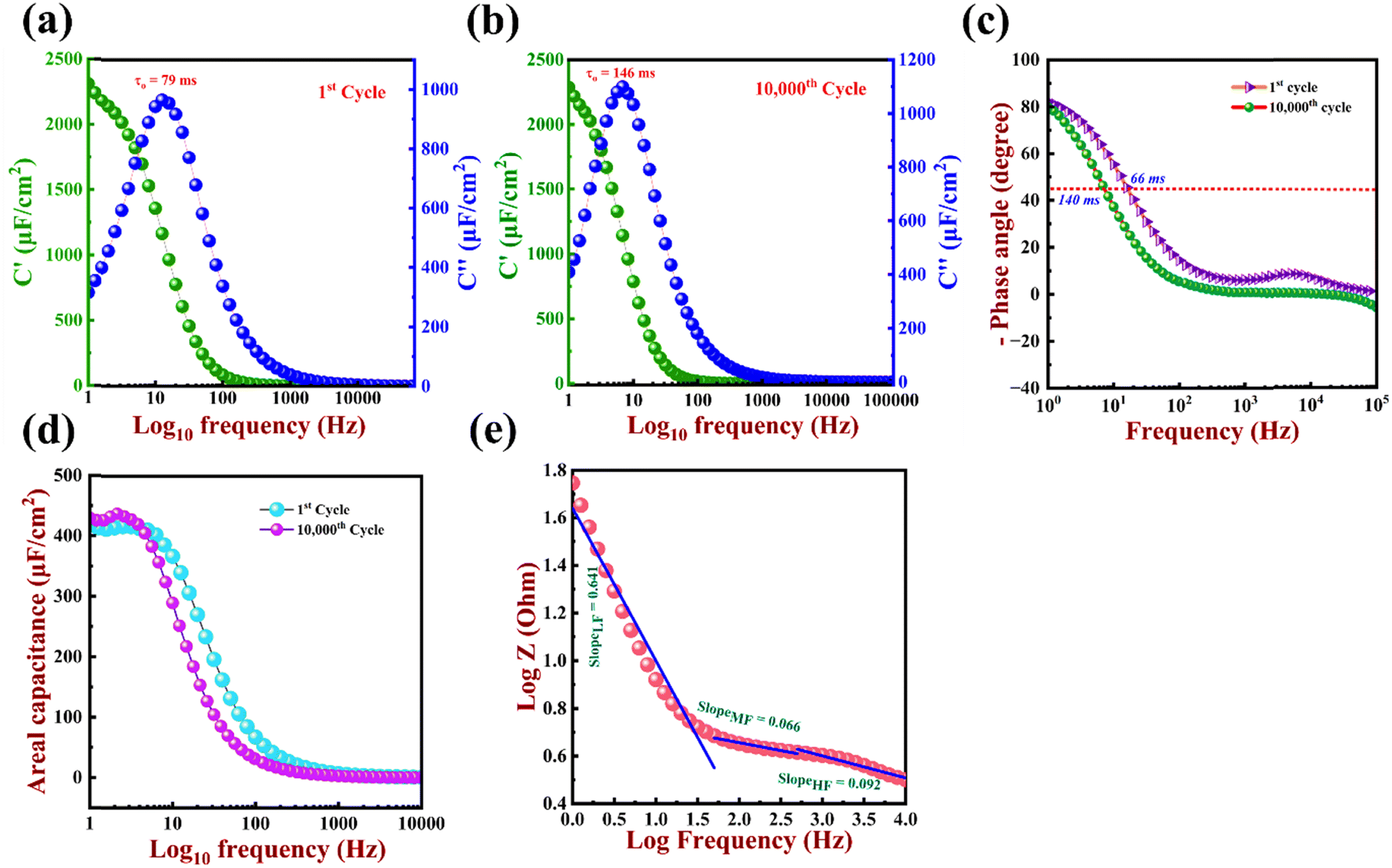
To acquire additional insights, the areal capacitance Ca was calculated using the EIS measurements as,55
| | 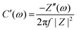 | (11) |
| |  | (12) |
| | | C(ω) = C′(ω) + C′′(ω) | (13) |
| |  | (14) |
C′(ω) and C′′(ω) stand for real and imaginary components of capacitance, while Z′(ω) and Z′′(ω) stand for real and imaginary components of impedance, respectively, with |Z| representing the Z modulus and f standing for frequency in Hz. Eqn (13) combines the real and imaginary components of the capacitance to determine the total capacitance (C(ω)). Fig. 11a and b show a comparative study of C′(ω) (left and bottom) and C′′(ω) (right and bottom) against frequency for the 1st and 10000th cycles, respectively, with specific capacitance measured in microfarad. These values cannot be compared with the earlier calculated specific capacitance using GCD since the deeply confined ions remain stationary in the electrolyte during the EIS measurements.56 The real element C′(ω) corresponds to the charge stored as a function of frequency, which is dependent upon the electrolyte's composition, mass loading, and porosity of the materials used. Subsequently, lower frequencies make it easier for electrolyte ions to penetrate deep inside the material pore, thereby leading to an increase in C′(ω). At mid-frequency, electrolyte ions are limited to the pore surface, and hence C′(ω) falls, while at high frequency it functions like a resistor, and C′(ω) becomes frequency-independent.57 The real component of capacitance at low frequencies represents the amount of capacitance stored in a system.58 Accordingly, from Fig. 11a and b, the order of C′(ω) at the 1st cycle is significantly larger than that at the 10000th cycle, i.e., C′(ω)1st = 2310 μF cm−2 > C′(ω)10000th = 2287 μF cm−2, which signifies that the efficiency decreases slightly after cycling. C′′(ω) varies with frequency, as seen in Fig. 11a and b for the 1st and 10000th cycle, respectively. The energy dissipation during the charge storage is indicated by the imaginary component C′′(ω).59C′′(ω) reaches a maximum at frequency fo, and the dielectric relaxation time constant (τo) for the entire system can be found by taking the inverse of this fo.60 It is a point at which the system reaches around half of its low-frequency capacitance and is also referred to as the supercapacitor factor of merit.55 Furthermore, the τo of the material after 10000 cycles is found to be 146 ms, which is higher than that of the 1st cycle (79 ms). This suggests that comparatively less time is required to release all the energy from the electrode at the 1st cycle than at the 10000th cycle. Fig. 11c shows the bode plot (phase angle vs. log frequency) at the 1st and 10000th cycle. A supercapacitor's characteristics vary between an ideal resistor (phase angle 0°) and an ideal capacitor (phase angle −90°).61 Interestingly, according to the graph, the phase angle within the low-frequency region at the 1st cycle (−82°) is closer to −90° than at the 10000th cycle (−79°), indicating that the electrodes have better capacitive behaviour at the 1st cycle. Another factor is the 'Knee frequency', which is the frequency at which the phase angle hits −45°, and is a point at which the capacitive and resistive impedances are equal.62 Beyond this, the supercapacitor exhibits greater resistive behaviour at higher frequencies. The relaxation time (τo = 1/fo) is the least time required to discharge all energy from a device with an efficiency above 50%.63 The relaxation time was determined to be 66 ms at 15 Hz and 140 ms at 7 Hz for the 1st and 10000th cycles, respectively. Thus, comparatively higher knee frequency values for the 1st cycle (mentioned above) also point to the ease of mass movement inside the electrode material. As seen in Fig. 11d, the areal capacitance at the 1st and 10000th cycle of the CoWO4‖AC asymmetric supercapacitor is plotted against the log frequency (Hz) from eqn (14). In both scenarios, the computed areal capacitance begins at 0.29 μF cm−2 at 10 KHz, suggesting that the electrode's resistive nature remains unchanged even after charging. The electrode's areal capacitance increases to 410 μF cm−2 during the first cycle. However, by the 10000th cycle, a slight decrease in capacitance is observed, particularly in the mid- and low-frequency regions. These values correspond to the previously stated Rs values and the knee frequency values. Three inclinations in the low-frequency (LF), high-frequency (HF), and mid-frequency (MF) regions can be seen in Fig. 11e (impedance bode plot). According to Fig. 11e, the LF (1–50 Hz) region had the highest slope value, followed by the HF (500–1000 Hz) and MF (50–500 Hz) regions. The resistive behaviour at the interface may be responsible for the high slope value in the low-frequency region, while a combination of both resistive and capacitive is shown in the high-frequency regions. The electrode's purely capacitive nature is depicted by the lowest slope in the mid-frequency region.64–66
 |
| | Fig. 11 (a) C′ and C′′ vs. frequency of CoWO4‖AC at the 1st cycle. (b) C′ and C′′ vs. frequency of CoWO4‖AC at the 10000th cycle. (c) The phase angle bode plot. (d) Areal capacitance vs. log frequency at the 1st and 10000th cycle. (e) Impedance bode plot. | |
The present study exhibits a CoWO4‖AC asymmetric device, which demonstrates excellent performance compared to several previously reported devices, as can be seen in Table 3. Despite the slightly lower potential window of 1.2 V, the device holds a significantly greater energy density of 51.8 W h kg−1 at a current density of 1 A g−1. Moreover, the device has exceptional cycling stability, maintaining its capacity for 10000 cycles.
Table 3 Comparative study of two electrode devices with the present work
| Material |
Type |
Potential window (V) |
Maximum energy density (W h kg−1) |
Number of cycles |
Ref. |
| CNT-CoWO4 |
Symmetric |
1.5 |
12 |
— |
67
|
| Co-B/CoWO4‖AC |
Asymmetric |
1.6 |
22.26 |
10000 |
68
|
| Co3O4@CoWO4/rGO‖AC |
Asymmetric |
1.7 |
19.1 |
5000 |
69
|
| NiWO4‖AC |
Asymmetric |
1.6 |
25.3 |
5000 |
70
|
| MnWxCo2−2xO4‖AC |
Asymmetric |
1.2 |
3.17 |
10000 |
71
|
| NiCo2O4–rGO‖AC |
Asymmetric |
1.4 |
10.5 |
2500 |
72
|
| Co(OH)2 |
Symmetric |
1.2 |
3.96 |
5000 |
73
|
| NiO–carbon |
Symmetric |
0.8 |
10.2 |
— |
74
|
|
CoWO
4
‖AC
|
Asymmetric
|
1.2
|
51.8
|
10![[thin space (1/6-em)]](https://www.rsc.org/images/entities/b_char_2009.gif) 000 000
|
Present work
|
3.9. Capacitive contribution
To examine the proportion of different capacitance, characterization and its respective principles are listed below. (1) Intercalation pseudocapacitance, (2) redox pseudocapacitance and (3) underpotential diffusion.75 The faradaic charge transfer principle accompanies both the intercalation and redox pseudocapacitance. In intercalation, cations are inserted into the layers of the active material without altering the crystal structure.76 While in redox pseudocapacitance, charge transfer occurs as ions are adsorbed onto or near the surface of the active material.77 Underpotential deposition is the phenomenon in which metal ions get adsorbed on different conducting surfaces to form a monolayer, it generally takes place when the potential is less negative than their redox potential.78 These capacitive contributions can be examined by evaluating redox peak current at varying scan rates as per the power law equation,79here i is current, and ν stands for scan rate, while a and b are adjustable values.
Taking logarithms on both sides of eqn (15),
| | | logi = logaνb = loga + blogν | (16) |
| |  | (17) |
From (17) it can be concluded that the slope of logi vs. logν plot gives b.
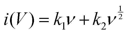
Specifically, the formula (15) can be expressed as i = aν1/2 when b = 0.5; this implies that intercalation of cations occurs and is primarily regulated by surface diffusion. Furthermore, in surface capacitive b = 1, so the formula can be expressed as i = Cdν; here, the current response is directly proportional to the scan rate, which illustrates that surface-controlled kinetics are dominant.80
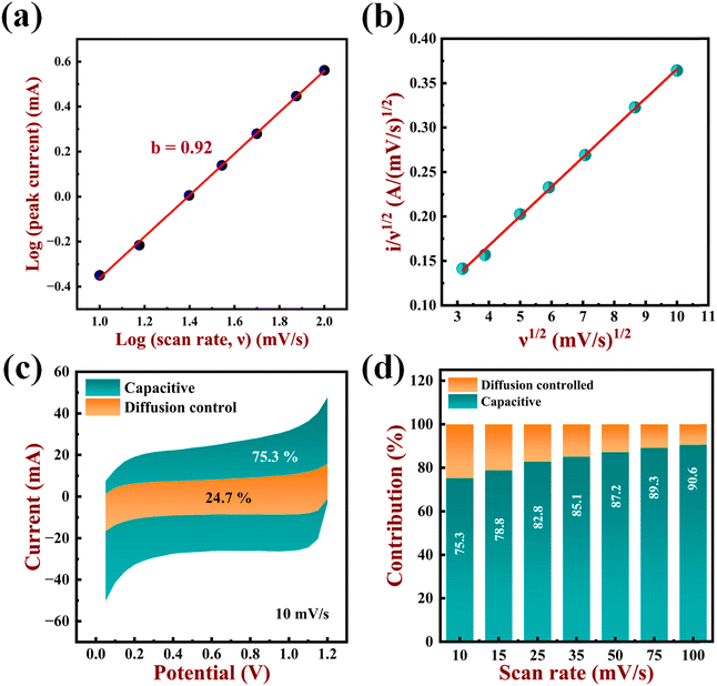
The b value for the anodic sweep at 1 V is 0.92, as can be seen in Fig. 12a. Since the b value is close to 1, it is evident that surface capacitance dominates the current. This is predominantly caused by redox pseudocapacitance behaviour, contrary to electric double-layer behaviour. The equation below can be used to further quantify the contribution of both processes (surface/diffusion controlled) to total charge storage.18
| |  | (18) |
The above equation can be simplified into,
| |  | (19) |
 |
| | Fig. 12 (a) logi vs. logν curve to get b value (b) i/ν1/2vs. ν1/2 curve at 1 V potential utilized to compute the values of k1 and k2. (c) Differentiating surface capacitive current and diffusion controlled current for the CoWO4 electrode at 10 mV s−1. (d) The ratio of capacitive contribution at varying scan rates from 10 mV s−1 to 100 mV s−1 for the CoWO4 electrode. | |
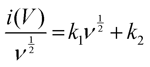
Here i(V) stands for current at a given potential, ν stands for scan rate while k1ν0.5 and k2 represent the current obtained from non-diffusion and diffusion-controlled intercalation mechanisms, respectively. By plotting the curve i(V)/ν0.5vs. ν0.5, one can quantify the values for k1 and k2. The slope of the above curve represents the k1 value, while its y-intercept represents the k2 value. The CV data at 10 mV s−1 were used to determine the values for k1 and k2 by fitting the curve according to eqn (19) (Fig. 12b). Additionally, the percentage contribution of the surface capacitive current (redox pseudocapacitive mechanism) and the ion intercalation current (diffusion-controlled mechanism) are determined, as can be seen in Fig. 12(c) and (d). From the figure, it is evident that the redox pseudocapacitive mechanism is in charge of this current. Additionally, it is demonstrated that, at a low scan rate of 10 mV s−1, the contribution of intercalation pseudocapacitance (orange region) and redox pseudocapacitance (navy blue region) to total capacitance is 24.7% and 75.3%, respectively. It is also observed that with the increase in scan rate from 10 mV s−1 to 100 mV s−1, the contribution of intercalation pseudocapacitive current decreases from 24.7% to 9.4%. This may be due to the restricted intercalation of ions into the lattice with the increase in the scan rate.81
4. Conclusions
The present research accounts for the successful synthesis of CoWO4 nanostructures through a straightforward, cost-effective, and low-temperature hydrothermal method. These nanostructures were demonstrated based on their structure as well as morphology using XRD with Rietveld refinement, Raman/FTIR spectroscopy, FE-SEM, and TEM images. A monoclinic structure with a (P2/c) space group was validated by XRD patterns and Rietveld refinement data. Raman/FTIR analysis further validates the material by detecting vibrational modes and confirming molecular composition and structural characteristics. FE-SEM images show spikes that form a morphology similar to that of a flower while TEM confirms distinct elongated oval structures, aligning well with FE-SEM findings. XPS analysis reveals Co 2p, W 4f, and O 1s peaks, along with a C 1s line, possibly indicating surface adsorption of hydrocarbons on the nanostructures. The CoWO4 electrode displays a high specific capacitance (138 F g−1 at 1 A g−1 current density in 6 M KOH) and maintains 93.25% capacity retention over 10000 charge–discharge cycles. In addition, the built CoWO4‖AC asymmetric supercapacitor device demonstrated an exceptional capacity retention of 96.43% after 10000 charge–discharge cycles and a high energy density of 51.9 W h kg−1. As a result, the produced electrode could serve as a possible electrode material for energy-efficient asymmetric supercapacitors.
Author contributions
Pruthvi B. Patel: methodology, investigation, data analysis, visualization, writing – original draft. Anita R. Patel, Dharti Patel, and Vanaraj Solanki: characterization and analysis of data. Sanjay N. Bariya: formal analysis, investigation, data curation, review, and editing. Yash G. Kapdi: measurements, formal analysis, review, and editing. Mitesh H. Patel and Saurabh S. Soni: conceptualization, methodology, review, and supervision.
Data availability
The data supporting this article have been included as part of the ESI.†
Conflicts of interest
The author declares no conflict of interest.
Acknowledgements
The authors Pruthvi B. Patel, Dharti Patel, Anita R. Patel, Sanjay N. Bariya, and Yash G. Kapdi are thankful to the Government of Gujarat for giving the “SHODH” Scholarship. The authors are also thankful to the management of Charotar University of Science and Technology and Dr K. C. Patel Research & Development Center for providing experimental facilities. The authors are also thankful to Department of Science and Technology-Anusandhan National Research Foundation (ANRF) for project funding (CRG/2023/001471).
References
- S. Chen, G. Yang, Y. Jia and H. Zheng, Facile Synthesis of CoWO4 Nanosheet Arrays Grown on Nickel Foam Substrates for Asymmetric Supercapacitors, ChemElectroChem, 2016, 3, 1490–1496 CrossRef CAS
 .
.
- R. Barik and P. P. Ingole, Challenges and prospects of metal sulfide materials for supercapacitors, Curr. Opin. Electrochem., 2020, 21, 327–334 CrossRef CAS .
- Y. Wang, L. Zhang, H. Hou, W. Xu, G. Duan, S. He, K. Liu and S. Jiang, Recent progress in carbon-based materials for supercapacitor electrodes: a review, J. Mater. Sci., 2021, 56, 173–200 CrossRef CAS .
- A. Pramitha and Y. Raviprakash, Recent developments and viable approaches for high-performance supercapacitors using transition metal-based electrode materials, J. Energy Storage, 2022, 49, 104120 CrossRef .
- Q. Meng, K. Cai, Y. Chen and L. Chen, Research progress on conducting polymer based supercapacitor electrode materials, Nano Energy, 2017, 36, 268–285 CrossRef CAS .
- Y. Zhang, L. Li, H. Su, W. Huang and X. Dong, Binary metal oxide: Advanced energy storage materials in supercapacitors, J. Mater. Chem. A, 2015, 3, 43–59 RSC .
- J. H. Ouyang, Y. F. Li, Y. Z. Zhang, Y. M. Wang and Y. J. Wang, High-Temperature Solid Lubricants and Self-Lubricating Composites: A Critical Review, Lubricants, 2022, 10, 1–59 RSC .
-
S. Pourmasoud, M. Eghbali-Arani, V. Ameri, M. Rahimi-Nasrabadi, F. Ahmadi and A. Sobhani-Nasab, Synthesis of some transition MWO 4 (M: Mn, Fe, Co, Ni, Cu, Zn, Cd) nanostructures by hydrothermal method, Springer, US, 2019, vol. 30 Search PubMed .
- K. Adib, M. Rahimi-Nasrabadi, Z. Rezvani, S. M. Pourmortazavi, F. Ahmadi, H. R. Naderi and M. R. Ganjali, Facile chemical synthesis of cobalt tungstates nanoparticles as high performance supercapacitor, J. Mater. Sci.: Mater. Electron., 2016, 27, 4541–4550 CrossRef CAS .
- K. Leeladevi, M. Arunpandian, J. Vinoth Kumar, T. Chellapandi, G. Mathumitha, J. W. Lee and E. R. Nagarajan, CoWO4 decorated ZnO nanocomposite: Efficient visible-light-activated photocatalyst for mitigation of noxious pollutants, Phys. B, 2022, 626, 413493 CrossRef CAS .
- S. M. Alshehri, J. Ahmed, T. Ahamad, P. Arunachalam, T. Ahmad and A. Khan, Bifunctional electro-catalytic performances of CoWO4 nanocubes for water redox reactions (OER/ORR), RSC Adv., 2017, 7, 45615–45623 RSC .
- R. C. Pullar, S. Farrah and N. M. N. Alford, MgWO4, ZnWO4, NiWO4 and CoWO4 microwave dielectric ceramics, J. Eur. Ceram. Soc., 2007, 27, 1059–1063 CrossRef CAS .
- P. K. Pandey, N. S. Bhave and R. B. Kharat, Characterization of spray deposited CoWO4 thin films for photovoltaic electrochemical studies, J. Mater. Sci., 2007, 42, 7927–7933 CrossRef CAS .
- T. N. Rezukhina and T. A. Kashina, Determination of the thermodynamic properties of Co3W, Co7W6, CoWO4, and Co-based solid solutions (Co + W) from a study of solid-electrolyte galvanic cells in the temperature range 1200 to 1360 K, J. Chem. Thermodyn., 1976, 8, 513–517 CrossRef CAS .
- G. He, J. Li, W. Li, B. Li, N. Noor, K. Xu, J. Hu and I. P. Parkin, One pot synthesis of nickel foam supported self-assembly of NiWO4 and CoWO4 nanostructures that act as high performance electrochemical capacitor electrodes, J. Mater. Chem. A, 2015, 3, 14272–14278 RSC .
-
H. V. S. B. Azevêdo, R. A. Raimundo, L. S. Ferreira, M. M. S. Silva, M. A. Morales, D. A. Macedo, U. U. Gomes and D. G. L. Cavalcante, Green synthesis of CoWO4 powders using agar-agar from red seaweed (Rhodophyta): Structure, magnetic properties and battery-like behavior, Mater. Chem. Phys., DOI:10.1016/j.matchemphys.2019.122544.
- X. Xing, Y. Gui, G. Zhang and C. Song, CoWO4 nanoparticles prepared by two methods displaying different structures and supercapacitive performances, Electrochim. Acta, 2015, 157, 15–22 CrossRef CAS .
- D. Chu, D. Guo, B. Xiao, L. Tan, H. Ma, H. Pang, X. Wang and Y. Jiang, 3D Hollow Flower-like CoWO4 Derived from ZIF-67 Grown on Ni-foam for High-Performance Asymmetrical Supercapacitors, Chem. – Asian J., 2020, 15, 1750–1755 CrossRef CAS PubMed .
- Y. L. Oliveira, A. F. Gouveia, M. J. S. Costa, F. H. P. Lopes, J. C. Sczancoski, E. Longo, G. E. Luz, R. S. Santos and L. S. Cavalcante, Investigation of electronic structure, morphological features, optical, colorimetric, and supercapacitor electrode properties of CoWO4 crystals, Mater. Sci. Energy Technol., 2022, 5, 125–144 CAS .
- S. S. Patil, U. M. Chougale, R. K. Kambale and V. J. Fulari, Hydrothermal synthesis of CoWO4 nanoparticles and evaluation of their supercapacitive performance, J. Energy Storage, 2023, 67, 107517 CrossRef .
- S. G. Krishnan, M. Harilal, B. Pal, I. I. Misnon, C. Karuppiah, C. C. Yang and R. Jose, Improving the symmetry of asymmetric supercapacitors using battery-type positive electrodes and activated carbon negative electrodes by mass and charge balance, J. Electroanal. Chem., 2017, 805, 126–132 CrossRef CAS .
- S. Prabhu, C. Balaji, M. Navaneethan, M. Selvaraj, N. Anandhan, D. Sivaganesh, S. Saravanakumar, P. Sivakumar and R. Ramesh, Investigation on mesoporous bimetallic tungstate nanostructure for high-performance solid-state supercapattery, J. Alloys Compd., 2021, 875, 160066 CrossRef CAS .
- S. Thongtem and S. Wannapop, Characterization of CoWO4 nano-particles produced using the spray pyrolysis, Ceram. Int., 2009, 35, 2087–2091 CrossRef CAS .
- E. Bandiello, P. Rodríguez-Hernández, A. Munoz, M. B. Buenestado, C. Popescu and D. Errandonea, Electronic properties and high-pressure behavior of wolframite-type CoWO4, Mater. Adv., 2021, 2, 5955–5966 RSC .
- M. Jeyakanthan, U. Subramanian and R. B. Tangsali, Enhanced photoluminescence of CoWO4 in CoWO4/PbWO4 nanocomposites, J. Mater. Sci.: Mater. Electron., 2018, 29, 1914–1924 CrossRef CAS .
- M. Rahimi-Nasrabadi, S. M. Pourmortazavi, Z. Rezvani, K. Adib and M. R. Ganjali, Facile synthesis optimization and structure characterization of zinc tungstate nanoparticles, Mater. Manuf. Processes, 2015, 30, 34–40 CrossRef CAS .
- S. M. Pourmortazavi, M. Rahimi-Nasrabadi, M. Khalilian-Shalamzari, H. R. Ghaeni and S. S. Hajimirsadeghi, Facile Chemical Synthesis and Characterization of Copper Tungstate Nanoparticles, J. Inorg. Organomet. Polym. Mater., 2014, 24, 333–339 CrossRef CAS .
- S. M. Pourmortazavi, M. Rahimi-Nasrabadi, Y. Fazli and M. Mohammad-Zadeh, Taguchi method assisted optimization of electrochemical synthesis and structural characterization of copper tungstate nanoparticles, Int. J. Refract. Met. Hard Mater., 2015, 51, 29–34 CrossRef CAS .
- S. M. Pourmortazavi, M. Rahimi-Nasrabadi, M. Khalilian-Shalamzari, M. M. Zahedi, S. S. Hajimirsadeghi and I. Omrani, Synthesis, structure characterization and catalytic activity of nickel tungstate nanoparticles, Appl. Surf. Sci., 2012, 263, 745–752 CrossRef CAS .
- M. Khalfaoui, S. Knani, M. A. Hachicha and A. Ben Lamine, New theoretical expressions for the five adsorption type isotherms classified by BET based on statistical physics treatment, J. Colloid Interface Sci., 2003, 263, 350–356 CrossRef CAS PubMed .
- Y. Li, X. Li, J. Wang, Y. Jun and Z. Tang, A cobalt tungstate compound sensing electrode for hydrogen detection based upon mixed-potential type sensors, RSC Adv., 2017, 7, 2919–2925 RSC .
- C. Zhang, D. Guo, C. Hu, Y. Chen, H. Liu, H. Zhang and X. Wang, Large-scale synthesis and photoluminescence of cobalt tungstate nanowires, Phys. Rev. B: Condens. Matter Mater. Phys., 2013, 87, 1–8 Search PubMed .
- A. Ammasi, A. P. Munusamy, M. Shkir, F. Maiz, B. Vellingiri, V. R. M. Reddy and W. K. Kim, Synthesis and electrochemical performance of CoWO4 and CoWO4/MWCNT nanocomposites for highly efficient supercapacitor applications, Diamond Relat. Mater., 2023, 139, 110352 CrossRef CAS .
- M. Zhang, H. Fan, X. Ren, N. Zhao, H. Peng, C. Wang, X. Wu, G. Dong, C. Long, W. Wang, Y. Gao, L. Ma, P. Wu, H. Li and X. Jiang, Study of pseudocapacitive contribution to superior energy storage of 3D heterostructure CoWO4/Co3O4 nanocone arrays, J. Power Sources, 2019, 418, 202–210 CrossRef CAS .
- A. Li, Y. Tu, Y. Zhu, D. Li, W. Zhou, X. Zhu and L. Feng, CoWO4 Nanoparticles Prepared in Different Solvents and Their Pseudocapacitant Performances, Int. J. Electrochem. Sci., 2017, 12, 5646–5656 CrossRef CAS .
- A. Zolfaghari, H. R. Naderi and H. R. Mortaheb, Carbon black/manganese dioxide composites synthesized by sonochemistry method for electrochemical supercapacitors, J. Electroanal. Chem., 2013, 697, 60–67 CrossRef CAS .
- H. K. Machhi, K. K. Sonigara, S. N. Bariya, H. P. Soni and S. S. Soni, Hierarchically Porous Metal-Organic Gel Hosting Catholyte for Limiting Iodine Diffusion and Self-Discharge Control in Sustainable Aqueous Zinc-I2Batteries, ACS Appl. Mater. Interfaces, 2021, 13, 21426–21435 CrossRef CAS PubMed .
- M. Jeyakanthan, U. Subramanian, R. B. Tangsali and A. Ramesh, AC conductivity, electrochemical and magnetic studies of CoWO4/PbWO4 nanocomposites, Phys. B, 2020, 586, 412151 CrossRef CAS .
- U. Nithiyanantham, S. R. Ede, T. Kesavan, P. Ragupathy, M. D. Mukadam, S. M. Yusuf and S. Kundu, Shape-selective formation of MnWO4 nanomaterials on a DNA scaffold: Magnetic, catalytic and supercapacitor studies, RSC Adv., 2014, 4, 38169–38181 RSC .
- R. Dhilip Kumar and S. Karuppuchamy, Microwave mediated synthesis of nanostructured Co -WO3 and CoWO4 for supercapacitor applications, J. Alloys Compd., 2016, 674, 384–391 CrossRef CAS .
- E. Sohouli, K. Adib, B. Maddah and M. Najafi, Manganese dioxide/cobalt tungstate/nitrogen-doped carbon nano-onions nanocomposite as new supercapacitor electrode, Ceram. Int., 2022, 48, 295–303 CrossRef CAS .
- X. Fan and X. Chen, Hydrothermal synthesis of flower-like CoWO4 with good supercapacitive performances, J. Alloys Compd., 2020, 2020, 215–220 Search PubMed .
- X. Xu, J. Shen, N. Li and M. Ye, Facile synthesis of reduced graphene oxide/CoWO4 nanocomposites with enhanced electrochemical performances for supercapacitors, J. Alloys Compd., 2014, 150, 23–34 CAS .
- U. Nithiyanantham, S. R. Ede, S. Anantharaj and S. Kundu, Self-assembled NiWO4 Nanoparticles (NPs) into chain-like Aggregates on DNA Scaffold with Pronounced Catalytic and Supercapacitor Activities Self-assembled NiWO 4 Nanoparticles (NPs) into chain-like Aggregates on DNA Scaffold with Pronounced Catalytic, J. Alloys Compd., 2015, 15, 673–686 CAS .
- R. D. Kumar and S. Karuppuchamy, Microwave-assisted synthesis of copper tungstate nanopowder for supercapacitor applications, J. Alloys Compd., 2014, 40, 12397–12402 Search PubMed .
- S. J. Patil, N. R. Chodankar, Y. S. Huh, Y. K. Han and D. W. Lee, Bottom-up Approach for Designing Cobalt Tungstate Nanospheres through Sulfur Amendment for High-Performance Hybrid Supercapacitors, ChemSusChem, 2021, 14, 1602–1611 CrossRef CAS PubMed .
- K. Thiagarajan, D. Balaji, J. Madhavan, J. Theerthagiri, S. J. Lee, K. Y. Kwon and M. Y. Choi, Cost-effective synthesis of efficient cowo4/ni nanocomposite electrode material for supercapacitor applications, Nanomaterials, 2020, 10, 1–12 Search PubMed .
- P. Prabakaran, S. Prabhu, M. Selvaraj, M. Navaneethan, P. Ramu and R. Ramesh, Synthesis of r-GO-incorporated CoWO4 nanostructure for high-performance supercapattery applications, J. Mater. Sci.: Mater. Electron., 2022, 33, 9312–9323 CrossRef CAS .
- G. Harichandran, P. Divya, J. Yesuraj and B. Muthuraaman, Sonochemical synthesis of chain-like ZnWO4 nanoarchitectures for high performance supercapacitor electrode application, Mater. Charact., 2020, 167, 110490 CrossRef CAS .
-
H. D. E. Uygun and Z. O. Uygun, Electrochemical Impedance Spectroscopy (EIS) Principles and Biosensing Applications, Handbook of Nanobioelectrochemistry: Application in Devices and Biomolecular Sensing, 2023, pp. 919–939 Search PubMed .
- B. Mandal and A. K. Thakur, Electrode response of NaFeTiO4 in aqueous supercapacitor cells, Ionics, 2021, 27, 1709–1721 CrossRef CAS .
- F. Lou and D. Chen, Aligned carbon nanostructures based 3D electrodes for energy storage, J. Energy Chem., 2015, 24, 559–586 CrossRef .
- B. E. Conway, V. Birss and J. Wojtowicz, The role and utilization of pseudocapacitance for energy storage by supercapacitors, J. Power Sources, 1997, 66, 1–14 CrossRef CAS .
- W. Wang, S. Guo, I. Lee, K. Ahmed, J. Zhong, Z. Favors, F. Zaera, M. Ozkan and C. S. Ozkan, Hydrous ruthenium oxide nanoparticles anchored to graphene and carbon nanotube hybrid foam for supercapacitors, Sci. Rep., 2014, 4, 9–14 Search PubMed .
- M. Arunkumar and A. Paul, Importance of Electrode Preparation Methodologies in Supercapacitor Applications, ACS Omega, 2017, 2, 8039–8050 CrossRef PubMed .
- N. Ponpandian, Nanoscale Advances Enhanced electrochemical activities of morphologically tuned MnFe 2 O 4 nanoneedles and nanoparticles integrated on reduced graphene oxide for highly e ffi cient supercapacitor electrodes †, Nanoscale Adv., 2021, 3, 2887–2901 RSC .
- P. L. Taberna, P. Simon and J. F. Fauvarque, Electrochemical Characteristics and Impedance Spectroscopy Studies of Carbon-Carbon Supercapacitors, J. Electrochem. Soc., 2003, 150, A292–A300 CrossRef CAS .
- S. N. Khatavkar and S. D. Sartale, Superior supercapacitive performance of grass-like CuO thin films deposited by liquid phase deposition †, New J. Chem., 2020, 6778–6790 RSC .
- P. Navalpotro, M. Anderson, R. Marcilla and J. Palma, Insights into the Energy Storage Mechanism of Hybrid Supercapacitors with Redox Electrolytes by Electrochemical Impedance Spectroscopy, Electrochim. Acta, 2018, 263, 110–117 CrossRef CAS .
- A. K. Shukla, A 1 V supercapacitor device with nanostructured graphene oxide/polyaniline composite materials, Bull. Mater. Sci., 2015, 38, 1507–1517 CrossRef .
- Z. Shi, L. Xing, Y. Liu, Y. Gao and J. Liu, A porous biomass-based sandwich-structured Co3O4@Carbon Fiber@Co3O4 composite for high-performance supercapacitors, Carbon, 2018, 129, 819–825 CrossRef CAS .
- T. Purkait, G. Singh, D. Kumar, M. Singh and R. S. Dey, High-performance flexible supercapacitors based on electrochemically tailored three-dimensional reduced graphene oxide networks, Sci. Rep., 2018, 8, 1–13 CAS .
- W. Liu, C. Lu, H. Li, R. Y. Tay, L. Sun, X. Wang, W. L. Chow, X. Wang, B. K. Tay, Z. Chen, J. Yan, K. Feng, G. Lui, R. Tjandra, L. Rasenthiram, G. Chiu and A. Yu, Paper-based all-solid-state flexible micro-supercapacitors with ultra-high rate and rapid frequency response capabilities, J. Mater. Chem. A, 2016, 4, 3754–3764 RSC .
- R. Ramachandran, M. Saranya, V. Velmurugan, B. P. C. Raghupathy, S. K. Jeong and A. N. Grace, Effect of reducing agent on graphene synthesis and its influence on charge storage towards supercapacitor applications, Appl. Energy, 2015, 153, 22–31 CrossRef CAS .
- R. Ramachandran, M. Saranya, C. Santhosh, V. Velmurugan, B. P. C. Raghupathy, S. K. Jeong and A. N. Grace, Co9S8 nanoflakes on graphene (Co9S 8/G) nanocomposites for high performance supercapacitors, RSC Adv., 2014, 4, 21151–21162 RSC .
-
R. Ramachandran, C. Zhao, D. Luo, K. Wang and F. Wang, Morphology-dependent electrochemical properties of cobalt-based metal organic frameworks for supercapacitor electrode materials, Elsevier Ltd, 2018, vol. 267 Search PubMed .
- V. Lokhande, S. J. Lee, A. Lokhande, J. H. Kim and T. Ji, 1.5 V Symmetric supercapacitor device based on hydrothermally synthesized Carbon nanotubes and Cobalt Tungstate nanocomposite electrodes, Mater. Chem. Phys., 2018, 211, 214–224 CrossRef CAS .
- J. F. Hou, J. F. Gao and L. Bin Kong, Interfacial engineering in crystalline cobalt tungstate/amorphous cobalt boride heterogeneous nanostructures for enhanced electrochemical performances, ACS Appl. Energy Mater., 2020, 3, 11470–11479 CrossRef CAS .
- X. Xu, Y. Yang, M. Wang, P. Dong, R. Baines, J. Shen and M. Ye, Straightforward synthesis of hierarchical Co3O4@CoWO4/rGO core-shell arrays on Ni as hybrid electrodes for asymmetric supercapacitors, Ceram. Int., 2016, 42, 10719–10725 CrossRef CAS .
- L. Niu, Z. Li, Y. Xu, J. Sun, W. Hong, X. Liu, J. Wang and S. Yang, Simple synthesis of amorphous NiWO4 nanostructure and its application as a novel cathode material for asymmetric supercapacitors, ACS Appl. Mater. Interfaces, 2013, 5, 8044–8052 CrossRef CAS PubMed .
- S. Ahmed, M. A. Gondal, J. A. Khan, M. A. Almessiere, A. Baykal, A. Ali and A. S. Alzahrani, Tuning the composition of manganese cobaltite spinel with tungsten for enhanced energy storage performance, Nano-Struct. Nano-Objects, 2024, 39, 101279 CrossRef CAS .
- X. Wang, W. S. Liu, X. Lu and P. S. Lee, Dodecyl sulfate-induced fast faradaic process in nickel cobalt oxide-reduced graphite oxide composite material and its application for asymmetric supercapacitor device, J. Mater. Chem., 2012, 22, 23114–23119 RSC .
- A. D. Jagadale, V. S. Kumbhar, D. S. Dhawale and C. D. Lokhande, Performance evaluation of symmetric supercapacitor based on cobalt hydroxide [Co(OH)2] thin film electrodes, Electrochim. Acta, 2013, 98, 32–38 CrossRef CAS .
- D. W. Wang, F. Li and H. M. Cheng, Hierarchical porous nickel oxide and carbon as electrode materials for asymmetric supercapacitor, J. Power Sources, 2008, 185, 1563–1568 CrossRef CAS .
- M. Zhang, H. Fan, X. Ren, N. Zhao, H. Peng, C. Wang, X. Wu, G. Dong, C. Long, W. Wang, Y. Gao, L. Ma, P. Wu, H. Li and X. Jiang, Study of pseudocapacitive contribution to superior energy storage of 3D heterostructure CoWO4/Co3O4 nanocone arrays, J. Power Sources, 2019, 418, 202–210 CrossRef CAS .
- T. Brezesinski, J. Wang, S. H. Tolbert and B. Dunn, Ordered mesoporous α-MoO3 with iso-oriented nanocrystalline walls for thin-film pseudocapacitors, Nat. Mater., 2010, 9, 146–151 CrossRef CAS PubMed .
- Y. Wang, Y. Song and Y. Xia, Electrochemical capacitors: Mechanism, materials, systems, characterization and applications, Chem. Soc. Rev., 2016, 45, 5925–5950 RSC .
- Y. Liu, S. P. Jiang and Z. Shao, Intercalation pseudocapacitance in electrochemical energy storage: recent advances in fundamental understanding and materials development, Mater. Today Adv., 2020, 7, 100072 CrossRef .
- W. Lu, J. Shen, P. Zhang, Y. Zhong, Y. Hu and X. W. (David) Lou, Construction of CoO/Co–Cu–S Hierarchical Tubular Heterostructures for Hybrid Supercapacitors, Angew. Chem., 2019, 131, 15587–15593 CrossRef .
- S. Chen, X. Zhou, X. Ma, L. Li, P. Sun and M. Zhang, Asymmetric supercapacitors with excellent rate
performance by integrating Co(OH)F nanorods and layered Ti3C2T: X paper, RSC Adv., 2019, 9, 30957–30963 RSC .
- H. S. Kim, J. B. Cook, H. Lin, J. S. Ko, S. H. Tolbert, V. Ozolins and B. Dunn, Oxygen vacancies enhance pseudocapacitive charge storage properties of MoO3−x, Nat. Mater., 2017, 16, 454–462 CrossRef CAS PubMed .
|
| This journal is © The Royal Society of Chemistry 2025 |
Click here to see how this site uses Cookies. View our privacy policy here. 
 Open Access Article
 This Open Access Article is licensed under a Creative Commons Attribution-Non Commercial 3.0 Unported Licence
 d,
Yash G.
Kapdi
d,
Yash G.
Kapdi


 ” indicate the integral area of the CV curve, and “S” denotes scan rate. The parameter “m” represents the quantity of active mass loaded on the working electrode, while “ΔV” denotes the potential range of the electrode material.9