
 Open Access Article
 This Open Access Article is licensed under a
 Creative Commons Attribution 3.0 Unported Licence
Three decades, three climates: environmental and material impacts on the long-term reliability of photovoltaic modules†
Ebrar
Özkalay‡
 *a,
Hugo
Quest‡
bc,
Anika
Gassner‡
de,
Alessandro
Virtuani
fg,
Gabriele C.
Eder
d,
Stefanie
Vorstoffel
h,
Claudia
Buerhop-Lutz
h,
Gabi
Friesen
a,
Christophe
Ballif
bf,
Matthias
Burri
i and
Christof
Bucher
i
*a,
Hugo
Quest‡
bc,
Anika
Gassner‡
de,
Alessandro
Virtuani
fg,
Gabriele C.
Eder
d,
Stefanie
Vorstoffel
h,
Claudia
Buerhop-Lutz
h,
Gabi
Friesen
a,
Christophe
Ballif
bf,
Matthias
Burri
i and
Christof
Bucher
i
aUniversity of Applied Sciences and Arts of Southern Switzerland (SUPSI), 6850 Mendrisio, Switzerland. E-mail: ebrar.ozkalay@supsi.ch
bÉcole Polytechnique Fédérale de Lausanne (EPFL), Institute of Electrical and Micro Engineering (IEM), Photovoltaics and Thin-Film Electronics Laboratory, 2002 Neuchâtel, Switzerland
c3S Swiss Solar Solutions AG, 3645 Gwatt (Thun), Switzerland
dOFI Austrian Research Institute for Chemistry and Technology, 1030 Vienna, Austria
eVienna University of Technology, Institute of Materials Science and Technology, Vienna, Austria
fSwiss Centre for Electronics and Microtechnology (CSEM), Sustainable Energy Center, 2002 Neuchâtel, Switzerland
gOfficina del Sole srl, 20145 Milan, Italy
hHelmholtz-Institut Erlangen Nürnberg für Erneuerbare Energien (HI ERN), Forschungszentrum Jülich GmbH, 91058 Erlangen, Germany
iBern University of Applied Sciences (BFH), Department of Engineering and Computer Science, Institute for Energy and Mobility Research, Laboratory for Photovoltaic Systems, 3400 Burgdorf, Switzerland
First published on 30th May 2025
Abstract
As the world has entered the terawatt age of photovoltaic (PV) deployment, ensuring long-term reliability is more critical than ever for the global energy transition. This study analyses the long-term performance of six PV systems in Switzerland over three decades, with more than 20 years of high-quality monitoring data. The plants feature modules from the same family (AM55 and SM55) installed across varying altitudes and climates, providing a unique dataset to compare performance trends under different operating conditions. Using the multi-annual year-on-year (multi-YoY) approach, system-level performance loss rates (PLR) were assessed, averaging just −0.24 ± 0.16% per year, well below the commonly reported range of −0.75% to −1% per year in the literature. Laboratory analyses further revealed that higher thermal stress in low-altitude systems (up to 20 °C warmer) accelerated encapsulant degradation and acetic acid formation, contributing to localised corrosion and higher performance losses. Importantly, the bill of materials (BOM) is identified as the most critical factor in ensuring PV module longevity – with modules manufactured with lower-quality materials showing markedly higher degradation rates – followed by climatic influences. Indoor laboratory measurements confirmed that most modules retained over 80% of their initial nominal power after 30–35 years in the field. These findings highlight the durability of early 1990s module designs featuring EVA encapsulants, Tedlar backsheets, and robust framed glass/foil structures, supporting lower levelised cost of energy (LCOE), reduced carbon footprints, and extended performance warranties.
Broader contextSolar photovoltaic (PV) electricity is now widely recognised as an affordable, clean and reliable energy source, playing a pivotal role in the energy transition. Its rapid implementation has the potential to help mitigate climate change by phasing out fossil fuel power stations; however, this will require reliable and long-lasting PV modules. While manufacturers typically provide performance warranties of 25 to 30 years, only a few PV modules and systems have demonstrated a proven operational lifetime exceeding 20 years. Current warranties and business plans rely on accelerated ageing tests, which, however, are subject to limitations and provide no insight into the effective lifetime of solar modules. A detailed analysis of six grid-connected PV systems installed in Switzerland during the late 1980s and early 1990s demonstrates that high-quality PV systems (and their components), when built with high-quality materials and components, can achieve lifetimes exceeding 30 years. This highlights their durability and long-term reliability. Through collaborative efforts, we correlated module degradation rates across diverse climates, altitudes, and module bill-of-materials (BOMs); utilised advanced methods to evaluate performance and ageing of modules; and extracted key insights from a 35-year-old solar module technology, highlighting its long-term reliability. |
1 Introduction
1.1 Ensuring reliability in the PV terawatt age
Photovoltaics (PV) is becoming the main electricity source for a renewable energy transition. In 2023, 70% of the renewable electricity capacity added came from PV, and total installations reached more than 1.6 TWp at the beginning of 2024, covering 8.3% of global electricity demand.1 As the global installed PV capacity has reached the terawatt scale, the reliability of PV modules, systems, and general components has become vital for the continued success of the technology. Extending the service lifetime of PV systems positively impacts the profitability of solar projects,2 while minimising their carbon footprint and the levelised cost of electricity (LCOE).3 PV now exhibits one of the lowest carbon footprints and LCOEs among all power-generating technologies.4 Manufacturers of PV modules – the “heart” of a PV plant, and the only major component of the system that, if well designed, will operate for the entire duration of a project with no substitution – typically provide performance warranties of 25 years, with a growing trend towards 30-year warranties. These warranties are based on accelerated ageing tests and modeling; however, actual operational data from PV modules in outdoor field conditions typically covers only 10 to 20 years,5 with limited datasets extending beyond 30 years.6,7 The reliability of these warranties remains uncertain, as accelerated ageing tests used by the industry such as qualification, safety, and certification tests, are not lifetime tests. Hence, data from systems with more than 30 years of operation are invaluable for assessing the true long-term potential of solar PV technology.1.2 Impact of climate and operating conditions
The reliability and degradation rates of PV modules are heavily influenced by local environmental stressors. Conditions such as ambient temperature, ultraviolet (UV) radiation, humidity, and mechanical loads from wind, snow or ice significantly impact module performance and longevity.8,9 Previous studies show clear correlations between environmental factors and module degradation rates. For instance, modules experiencing high-temperature and high-UV irradiation exhibit faster performance losses than those in moderate climates.10 In regions where extreme weather events such as heavy snowfall or strong winds are frequent, they can lead to sudden – often catastrophic – failures, such as glass breakage, cell ruptures or structural damage, especially when PV module types are used that are not designed for such high mechanical stresses.11 These sporadic, severe events often remain unaccounted for in generalised degradation models, as they are difficult to predict.8,12 Other studies, however, suggest that it is not UV but temperature in particular that is a relevant catalyst for degradation.13 Monitoring and measurement data on PV system performance in alpine and other extreme climates is limited. Typically, only small-scale systems are deployed in such regions, often on remote structures like mountain huts. As such, this study aims to provide new insights into PV performance in challenging environments, helping to close critical knowledge gaps regarding PV reliability and degradation in harsh climates.1.3 Insights from decades of operation
This work provides a unique perspective on long-term PV performance by analysing 20–30 years of high-quality monitoring data from six PV systems equipped with similar module technology. The systems are located across Switzerland, facing diverse climatic conditions ranging from low-altitude to high-altitude (alpine) regions. By combining performance monitoring data with laboratory analyses of material degradation, this study enables a detailed evaluation of system-level performance loss rates (PLR) and the ageing mechanisms of modules. The results provide insights into the correlation between long-term performance and (i) system location and climate (low-altitude, mid-altitude and high-altitude (alpine)), (ii) mounting configuration (e.g. ground-mounted or building-applied), (iii) and bill-of-material (BOM) variations. Additionally, the study assesses lessons learned from a 35-year-old PV technology, contextualised against the rapid evolution of module design in recent decades. Overall, this work aims to fill critical gaps in understanding PV system reliability by linking electrical degradation with material analysis and comparing findings across diverse climatic conditions, offering valuable lessons for improving module design and performance assessments in the PV terawatt age.2 Methods
The datasets in this study provide a unique opportunity to analyse and characterise system- and module-level performance changes over more than 30 years of operation. The analysis follows two complementary approaches. First, a data-driven approach leverages long-term system monitoring and meteorological data to quantify the impact of different operating conditions on performance. Second, laboratory measurements of selected modules enable a detailed assessment of electrical and material degradation. A flowchart summarises the analysis methodologies employed in this study (Fig. 1). The methods are organised as follows: Section 2.1 describes the sites and systems, Section 2.2 details the module types used in these systems, Section 2.3 outlines the system-level outdoor data analysis, and Section 2.4 delves into the module-level indoor measurements. | ||
| Fig. 1 Flowchart illustrating the analysis methods in this study, combining system-level monitoring for climate characterisation and long-term performance assessment, and module-level indoor measurements for electrical and material characterisation. Abbreviations: PV (photovoltaics), multi-YoY (multi-annual year-on-year), PLR (performance loss rate), I–V curve (current–voltage characteristic), EL (electroluminescence), NIR (near-infrared), UVF (ultraviolet fluorescence), ATR-IR (attenuated total reflection infrared), TD-GC/MS (thermo-desorption gas chromatography/mass spectrometry). | ||
2.1 Monitored sites and systems
The plant layouts, module types, and locations are illustrated in Fig. 2, while a summary of PV system metadata is provided in Table 1.14,15 Each system is assigned a unique Site ID, constructed using the format [Altitude]–[Mounting Config.]–[Module Type], which will be used throughout the paper. The studied PV systems are classified into three altitude zones: low-altitude (<600 m), mid-altitude (1000–1500 m), and high-altitude (>2500 m), each corresponding to distinct Köppen-Geiger (KG) climate classifications: Cfb (temperate, no dry season, warm summer), Dfb (Cold, no dry season, warm summer), and ET (Polar, tundra).16 The low-altitude sites include Switzerland's first private grid-connected PV system in Möhlin (310m-VR-AM55), Tiergarten East and West in Burgdorf (533m-VR-SM55(HO) and 533m-VR-SM55HO), and Burgdorf Fink (552m-BA-SM55), featuring ventilated and building-applied rooftop configurations. At mid-altitude, Mont-Soleil (1270m-OR-SM55) hosts Europe's first utility-scale PV plant. The high-altitude systems, Birg (2677m-VF-AM55) and Jungfraujoch (3462m-VF-SM75), are facade-mounted installations. For most systems, on-site monitoring equipment measured the AC and DC outputs (current, voltage and power), as well as ambient and module temperature, and in-plane irradiance from pyranometers. Detailed system descriptions, including layout specifications, module types, and data availability, are presented in the Appendix (ESI Section A.1).† | ||
| Fig. 2 System photos, showing the profile view (top) and aerial view (bottom). Approximate location in Switzerland is indicated in the bottom right corner. The Tiergarten system is separated in the East and West parts of the rooftop in the data and results. Site IDs are indicated below the system name, following the defined format: [Altitude]–[Mounting Config.]–[Module Type], see Table 1. | ||
| Low-alt. | Mid-alt. | High-alt. | |||||
|---|---|---|---|---|---|---|---|
| Site ID | 310m-VR-AM55 | 533m-VR-SM55(HO) | 533m-VR-SM55HO | 552m-BA-SM55 | 1270m-OR-SM55 | 2677m-VF-AM55 | 3462m-VF-SM75 |
| Site name | Möhlin | Tiergarten West | Tiergarten East | Burgdorf Fink | Mont-Soleil | Birg | Jungfraujoch |
| Altitude [m a.s.l.] | 310 | 533 | 533 | 552 | 1270 | 2677 | 3462 |
| Köppen-Geigger climate zone | Cfb | Cfb | Cfb | Cfb | Dfb | ET | ET |
| Mounting config. | Ventilated roof (VR) | Ventilated roof (VR) | Ventilated roof (VR) | Building applied (BA) | Open-rack (OR) | Ventilated facade (VF) | Ventilated facade (VF) |
| Module type | AM55 | SM55-HO (94%), SM55 (6%) | SM55-HO | SM55 | SM55 | SM55 | SM75 |
| Capacity [kW p] | 2.64 | 22.2 | 25.81 | 3.18 | 554.592 | 2.226 | 1.152 |
| Orientation [°] | 157 (SE) | 209 (SW) | 209 (SW) | 168 (SE) | 153 (SE) | 190 (SW) | 200 (SW) |
| Tilt [°] | 36 | 30 | 30 | 28 | 52 | 90 | 90 |
| Installation year | 1987 | 1993 | 1993 | 1992 | 1992 | 1992 | 1993 |
| Data availability | N/A | 2002–2022 | 2002–2022 | 1992–2023 | 2001–2022 | 1992–2022 | 1993–2022 |
| Indoor meas. | Yes | Yes | N/A | N/A | Yes | Yes | Yes |
2.2 PV module description
All PV installations analysed in this study used modules from the same product family: ARCO AM55, Siemens SM55 (including the SM55-HO, “high output” variant), and Siemens SM75, manufactured and installed between 1987 and 1993. In 1990, Siemens Solar acquired ARCO Solar and the associated plant in Camarillo, California, where all the modules studied in this work were manufactured.17 This acquisition is also reflected in the naming of the modules. The nominal maximum power indicated on the nameplate is 55 W for most modules (48 W for the SM75), with an open-circuit voltage (Voc) of 21.7 V and a short-circuit current (Isc) of 3.45 A, subject to minor variations between individual modules. Fig. 3a shows a photograph of the SM55 module. | ||
| Fig. 3 (a) Photograph of a Siemens SM55 module. (b) Light micrograph of the cross section of part of the module laminate: 3-layer backsheet, back encapsulant and Si-solar cell. | ||
Each module comprises a multi-layer structure of glass front sheet (3.3 ± 0.1 mm thickness), ethylene-vinyl acetate (EVA) encapsulant, monocrystalline silicon (Si) solar cells, a second EVA encapsulant layer, and a polymer backsheet laminate18 (Fig. 3b). The monocrystalline Si cells are interconnected by two busbars, with cell thickness ranging from 265 to 460 μm as determined from cross-sectional measurements of various modules from each site. The modules feature a 3 × 12 cell configuration, resulting in dimensions of 329 × 1297 mm. Two junction boxes on the back of each module house bypass diodes, while anodised aluminium frames provide structural support. The backsheet is a laminated three-layer structure of polyvinyl fluoride (PVF)/polyethylene terephthalate (PET)/PVF (commonly known as “Tedlar”), where the PVF layers incorporate filler mainly of titanium dioxide (TiO2) and some samples with talc (Mg3Si4O10(OH)2). For the occasionally used SM55-HO variant, calcium carbonate (CaCO3) was identified as inorganic filler material (see Section 3.2.1). Backsheet thickness across all modules was consistently measured at 175 ± 7 μm. The EVA encapsulant thickness also varied between modules produced during this period, ranging from 370 to 500 μm based on the measured samples. Although all modules are similar and comparable, minor differences make it necessary to refer to the naming conventions (Table 1). The differences can be summarised as follows: (i) the Siemens SM75 has a lower maximum power output (48 W instead of 55 W); (ii) the AM55 modules are the oldest and therefore still lack certain encapsulation improvements; (iii) the SM55-HO variant has a different filler in the backsheet for higher reflectivity.
For benchmarking purposes, two Siemens M55 (SM55) modules have been stored in a controlled indoor environment at the Photovoltaic Laboratory of the Bern University of Applied Sciences (PV-Lab of BFH) since the start of the monitoring campaign. These unexposed modules serve as reference samples to evaluate material stability and potential ageing effects, independent of outdoor environmental stressors.
2.3 System-level monitoring and data-based analyses
The following sections will describe the methodology applied to the system-level outdoor monitoring data, starting with the meteorological data, in order to characterise the different climates, and followed by the PV system power data, with the goal of quantifying the PLR. As a general comment, operational records, including change logs and maintenance diaries, were maintained for most of the sites, revealing that nearly all systems underwent at least one inverter replacement over their 30+ years of operation. The monitoring setup employed high-quality measurement equipment, ensuring robust data acquisition; however, some aspects of long-term sensor stability and maintenance require further discussion. One key source of uncertainty in the dataset arises from the calibration and cleaning frequency of pyranometers used for irradiance measurements. Pyranometers are prone to sensor drift over extended periods, which can result in gradual deviations from their original calibration.19 This drift may be attributed to several factors, such as ageing of optical components, exposure to environmental dust or snow accumulation, or potential degradation of sensor electronics. The absence of a consistent recalibration schedule across all sites introduces potential biases in irradiance readings, which in turn affect the accuracy of performance assessments. To mitigate these uncertainties, data processing techniques were applied to detect and compensate for potential sensor drift. This includes comparing historical trends in irradiance data with external reference datasets and satellite-based measurements from Copernicus Atmosphere Monitoring Service (CAMS),20 and implementing filtering techniques to reduce noise from anomalous measurements. As a result of this data quality assessment, adjustments were made to three sites: site 552m-BA-SM55 data was truncated to the period 1993–2015 due to a combination of inverter replacements and changes in the site's module layout, which could have introduced inconsistencies in performance evaluation; sites 2677m-VF-AM55 and 3462m-VF-SM75 were shortened by 2 and 6 years respectively due to irradiance sensor drift, which affected data reliability.Temperature is a critical factor that influences both the short- and long-term performance of PV modules: higher temperatures reduce the power output of the modules due to the solar cell temperature coefficient, and accelerate the degradation of polymeric materials and other components.22–24 Additionally, temperature fluctuations lead to thermomechanical stresses due to differences in the thermal expansion coefficients of the module materials.25,26 Metrics that describe both the general temperature ranges of exposure as well as temperature fluctuations should therefore be evaluated in order to differentiate the various climates.27 The temperature probability density assesses the likelihood of specific temperature values throughout a studied time period, and allows to compare the frequency of temperature occurrences across various locations and system mounting configurations. The 98th percentile temperature (T98), as defined in the IEC TS 63126,28 represents the temperature value that is exceeded only 2% of the time. This corresponds to a cumulative exposure of 175.2 h per year at or above the T98 temperature, combining high temperature exposure and time spent at high temperatures.29,30 The T98 metric is considered more representative for thermal stress characterisation than the maximum temperature, which could reflect only a single occurrence, as thermal processes need time to activate.31 Diurnal temperature variation, defined as the difference between daily maximum and minimum temperatures, is another significant metric which provides an overview of daily thermal fluctuation. Higher day–night temperature variations are associated with higher thermomechanical stress, which could increase the risk of damage to metallic contacts, solder joints and cells.29 To further capture thermomechanical stress, the total temperature travelled metric is also used, calculated as the cumulative sum of absolute temperature changes at each time step. This metric typically provides a standardised approach for comparing thermal exposure across climates.32,33 Since it accounts for both positive and negative gradients, it reflects the total thermomechanical stress imposed by all intra-day temperature variations on PV modules (including day–night cycles but also cloud-related temperature drops), giving a generalised measure of accumulated stress.27
Irradiance is also a critical environmental factor that directly impacts PV module performance and degradation. To characterise irradiance conditions, plane-of-array (POA) irradiance probability density plots are used, filtering data for values above 50 W m−2 to exclude nighttime, ensuring that only relevant sunlight exposure is considered. This enables comparison of the distribution of irradiance levels across different locations, providing insight into the frequency of varying irradiance intensities each system experiences. Additionally, the total POA irradiation is calculated to quantify the cumulative light received by each system over the study period.
(1) Data gathering and pre-processing: system-level DC or AC power (inverter measurements), in-plane irradiance (from on-site POA pyranometers), and back-of-module temperature measurements are collected for each site. All data is resampled to 10-min average.
(2) Computing the performance metric: the temperature-corrected performance ratio (denoted PR′) is computed, following the IEC 61724-1:2021 guidelines.39Eqn (1) shows the calculation: for the k time steps with recording interval τ, Pmp [W] is the measured DC or AC power (in this work, DC power is used for all systems), P0 [W p] the rated power (system capacity), Gi [W m−2] the measured in-plane irradiance, and Gi,ref = 1000 W m−2 the irradiance at which P0 is determined, i.e. at standard test conditions (STC). The power rating temperature adjustment factor Ck,25°C is defined with Tmod [°C−1] the module temperature and γ [°C−1] the relative maximum-power temperature coefficient.
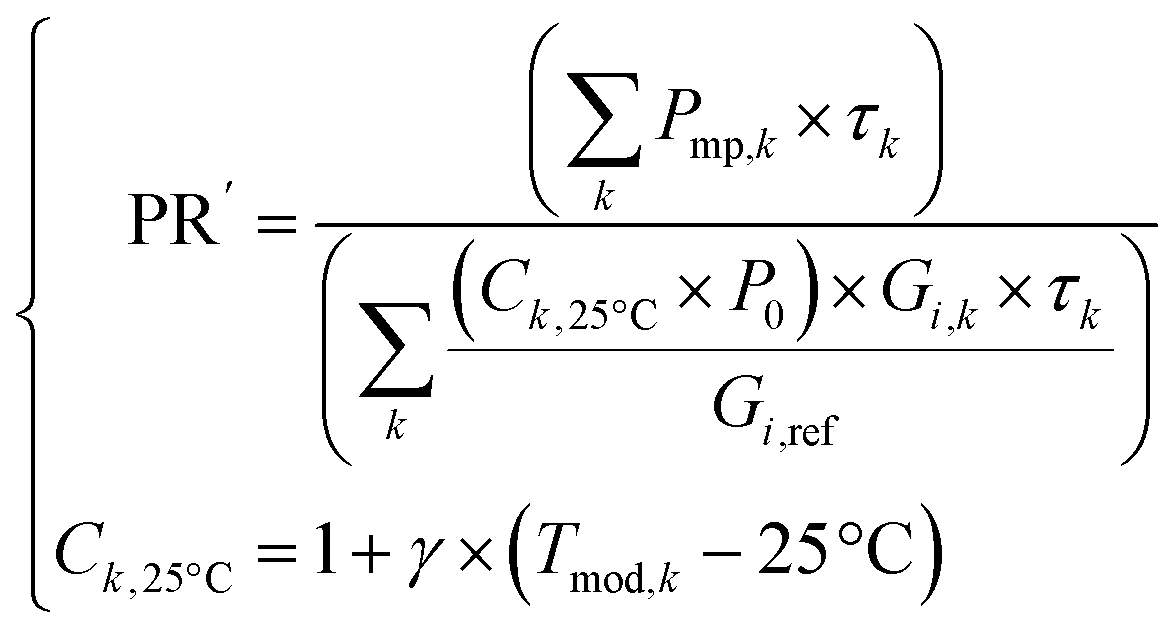 | (1) |
(3) Filtering and data aggregation: the PR′ time series are filtered and prepared for the multi-YoY analysis step. The same three-step filtering approach is applied to all datasets across the different sites:
(a) POA irradiance filter: data are filtered to exclude extreme irradiance conditions, such as nighttime, low-light, or irradiance peaks caused by cloud reflections, by removing values where irradiance is below 100 W m−2 or above 1250 W m−2. This step is applied to the 10-minute time series.
(b) PR′ filter: a PR′ filter is applied with low and high thresholds of 0.6 and 1.2, respectively, to remove extreme performance outliers. This step is also applied to the 10-minute time series.
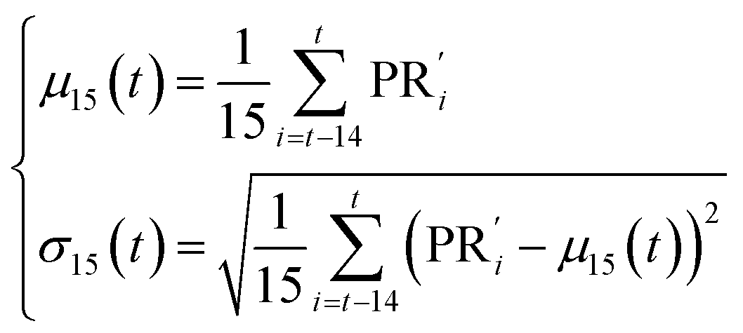
(c) Statistical outlier filter using rolling mean: statistical outliers are removed based on a rolling mean and standard deviation. In this third step, daily aggregated PR′ values are used to compute a 15-day rolling mean and standard deviation, creating upper and lower bounds for outlier detection. Specifically, the rolling mean μ15 and rolling standard deviation σ15 are calculated as follows:
 | (2) |
(d) Data aggregation: after applying the initial filters, the remaining data are aggregated to compute daily, weekly, monthly, or yearly mean values, forming the input for the multi-YoY analysis step.
(4) Determining the PLR: after computing, filtering, and aggregating the PR′ time series, the YoY changes are calculated to identify performance shifts across all subsequent years for each reference year. Instead of comparing only consecutive years (as in the standard YoY approach), the multi-YoY method compares the PR′ value for a given year i to the values in all subsequent years j (j > i), where  is the mean PR′ in year i,
  is the mean value in year j, and Δt is the time difference between the two years in years. This approach generates a larger distribution of YoY instances, improving accuracy and reducing statistical uncertainty by increasing the sample size.27
 | (3) |
The PLR is determined by calculating the median of the resulting YoY distribution, providing a robust measure less sensitive to outliers than the average. To capture the uncertainty around this PLR, bootstrapping is used.34 Bootstrapping creates random resamples from the data to simulate the variation in PLR values, allowing for the estimation of a confidence interval (CI).
2.4 Module-level indoor measurements
To complement the long-term monitoring data, a sample of PV modules was randomly selected and removed from the specified systems (Table 1). These modules were then subjected to indoor laboratory measurements (Fig. 1), and compared to the two reference SM55 modules that were not exposed to outdoor conditions. These tests provide a more in-depth investigation into the physical and electrical degradation mechanisms affecting the modules after prolonged field exposure. The following sections outline the methodologies applied across two main areas: electrical and material characterisation.Electroluminescence (EL) imaging is a widely used, rapid, and non-destructive technique for detecting defects in PV modules, such as cell cracks, damaged metallization, and shunts. The method works by injecting a direct current into the PV module, which stimulates radiative recombination in the solar cells. The resulting photon emission, occurring in the near-infrared region, is captured using a charge-coupled device (CCD) camera. In this work, EL imaging was conducted in a dark room, applying the Isc of the module under test.
Non-destructive near-infrared (NIR) measurements were carried out using a handheld spectrometer (trinamiX) in the range of 4080–6900 cm−1 (corresponding to 2450–1450 nm) and a spectral resolution of 1%. In the NIR range, light penetrates the entire polymer stack and the transparent glass pane, allowing analysis and identification of the 3-layer polymer backsheet and encapsulant. The backsheet layers are analysed by measuring from the back of the module, while the encapsulant is examined through the glass pane from the front of the module (above the Si-cell). To assess degradation within the polymer stack, it is necessary to further process the NIR spectra. Chemometric models, including Principal Component Analysis (PCA) and Random Forest (RDF), were applied using Epina DataLab software.40 PCA, a widely used clustering technique, reduces the dimensionality of multivariate data by transforming it into new variables (principal components) that capture the highest variance, often revealing patterns within the first two or three components. It is often used to visualise different clusters of data.41 RDF is a machine learning algorithm that builds multiple decision trees and combines their outputs to classify particular data sets. Each tree in the forest is built on a random subset of the data variables to create uncorrelated trees.42 The variable importance plot shows the variables that are most important to the classifier. In the context of analysing differently aged modules, this plot reveals the wavelengths associated with key chemical changes.
Destructive analysis allows for a detailed analysis of the materials and thickness of the individual layers. Therefore, cross-sections of the module laminate (excluding the glass) were prepared and analysed with an optical light microscopy. The thickness of the individual layers (backsheet, encapsulant, solar cell) were determined on at least two independent samples per system to ensure accuracy and reproducibility. This was followed by destructive attenuated total reflection infrared (ATR-IR) imaging in order to determine the chemical identity of each laminate layer. The cross-sections were analysed with a Fourier Transform Infrared (FTIR)-microscope.43 An FTIR spectrometer (PerkinElmer Model Spectrum One) combined with an Auto Image microscope (PerkinElmer Spotlight 400) was used. It is equipped with a liquid nitrogen cooled mercury–cadmium–telluride (MCT, line array) detector and an ATR imaging device. The germanium ATR-crystal with a flattened tip (d ∼ 800 μm) allows the collection of hyperspectral images as large as 500 × 500 μm. The spectral data in the image were processed using PCA to reveal spectral differences in the materials. In this kind of representation, each spectroscopic distinguishable component is displayed in a different colour. The mean spectra of the individual layers were extracted from these images. Additionally, compare-correlation images were generated using extracted spectra of the reference sample to confirm the presence of specific layers, such as the polyurethane-based adhesive layer (∼5–7 μm).
Thermo-desorption gas chromatography/mass spectrometry (TD-GC/MS) was performed to analyse thermally extractable components of the EVA encapsulant, such as additives and degradation products (e.g. acetic acid). A thermodesorption system Gerstel TDS 3 with a liquid nitrogen cooled injection system was used. The evolving gases were analysed by gas chromatography (GC) – Agilent 6890 GC – with a mass spectrometric (MS) detector HP 5973 N. The encapsulant samples were extracted at 150 °C for 30 min in He atmosphere. Using a defined sample weight of 10 mg allows for comparative quantitative evaluation of the thermally extracted components, such as acetic acid.
UV-fluorescence (UVF) imaging technique is based on the non-destructive detection of the fluorescence effects in the polymeric material of a PV module after UV light excitation. Certain electron-rich molecules, such as additives with aromatic rings or degraded polymer fragments with conjugated double bonds, are prone to form fluorophores that absorb UV light and re-emit light in the visible range.44 Thus, the emitted light has a longer wavelength (lower energy) than the absorbed UV light, making it visible to the naked eye, and is detectable with a photographic camera. In this study, UV light sources (with an emission maximum of 365 nm) and a camera (equipped with a high-pass filter to cut off UV light) were used. UVF imaging was performed in a darkroom to detect fluorescence effects associated with encapsulant degradation in the weathered modules.
3 Results
The results section first presents a comprehensive analysis of the operating conditions of the PV systems installed at varying altitudes in different applications (open rack, ventilated roof or facade and building attached). Results of the system-level PLR analysis after more than 30 years of outdoor exposure are then described and evaluated in conjunction with the results of detailed module-level electrical and material characterisation in the laboratory. The resulting degradation effects and failures are described and comparatively evaluated.3.1 Climate and operating conditions
The statistical analysis of the weather data based on the indicators described in Section 2.3.1 help to capture and understand the microclimates affecting each PV system, in terms of thermal, thermo-mechanical and irradiance stress. All findings are derived from 13 years of meteorological data collected at the sites (Fig. 4). In terms of thermal stress, module and ambient temperature probability densities (Fig. 4a and c) reveal that high-altitude locations provide the coldest operating conditions (minimum −31 °C), while the building-applied rooftop system at low-altitude location reaches the highest module temperatures (maximum 74 °C). Module T98 (Fig. 4b) is influenced not only by site altitude but also by system mounting configuration, explaining why the mid-altitude open-rack system (1270m-OR-SM55) has the lowest T98 at 40 °C. For ambient T98 (Fig. 4d), high-altitude locations show the lowest values, at 10 °C and 15 °C. Overall, in terms of expected thermal stress, the BAPV low-altitude system (552m-BA-SM55) experiences the most demanding operating conditions. | ||
| Fig. 4 Statistical analysis of the meteorological data. (a)–(d) Thermal stress: module and ambient temperature distributions and 98th percentile temperatures. (e) and (f) Thermo-mechanical stress: diurnal temperature variation distributions and total temperature travelled. (g) and (h) Irradiance stress: plane-of-array irradiance distribution (values 50 W m−2 filtered out to avoid nighttime and low irradiance) and total irradiation. All datasets are filtered between 2005–2018 to compare the same time periods and number of years. | ||
The probability density of diurnal temperature variation at the module level and the total temperature travelled are used to evaluate thermo-mechanical stress (Fig. 4e and f). Diurnal temperature variations reflect intra-day thermo-mechanical stress in module components due to differences in thermal expansion coefficients. Results indicate that the highest-altitude site (3462m-VF-SM75) experiences the greatest day–night temperature variations, likely due to freezing nighttime temperatures. In the mid- and low-altitude range, the BAPV system (552m-BA-SM55) exhibits the largest diurnal temperature variations, which may be attributed to reduced ventilation compared to open-rack or ventilated roof configurations. On top of day–night temperature fluctuations, total accumulated thermo-mechanical stress is estimated by the total temperature travelled. Interestingly, low-altitude ventilated roofs show the highest temperature travelled, likely due to faster cooling rates and thus lower thermal inertia. In contrast, the BAPV system has the lowest total temperature traversed, reflecting higher thermal inertia. Overall, frequent temperature ramping events induce material stress, with thermo-mechanical stress appearing more pronounced in low- to mid-altitude systems with partial ventilation.
Irradiance stress is analysed through the probability density of POA irradiance (where values <50 W m−2 are filtered out to avoid nighttime) and the total accumulated irradiance (Fig. 4g and h, respectively). Alpine sites show distinct irradiance distributions, with peak values exceeding 1400 W m−2, likely due to a combination of high solar irradiance resulting from reduced atmospheric thickness at high altitudes, snow reflectance (high albedo), and cloud reflections. Regarding total received irradiance, only the highest-altitude site exhibits a notably high level, which may contribute to increased photo-thermal stress or enhanced UV-induced degradation at the module level.
3.2 Long-term system performance
The PLR of all monitored systems is determined using the multi-YoY approach described in Section 2.3.2. The PR′ trends using yearly aggregation show the relative system performances over time (Fig. 5a). The PV system installation dates are indicated with arrows (the initial PR′ value is not based on a measurement but simply placed as a visual reference), to show the extent of outdoor module exposure relative to the monitoring data available for the PLR assessment. The final PLR value and 95% CI are based on the daily aggregation results which feature the lowest uncertainty (Fig. 5b). The detailed multi-YoY results per system are shown in the Appendix (Fig. A.1, ESI),† with the PLR results for daily, weekly, monthly and yearly aggregation strategies. | ||
| Fig. 5 (a) Temperature-corrected performance ratio (PR′) trends, using yearly data aggregation and smoothed with a Gaussian filter (σ = 2). The CI is computed using one standard deviation of the yearly averaged data. (b) PLR results with 95% CI from the daily aggregation results of the multi-YoY method. All systems with long-term performance data are included. | ||
The PR′ trend results highlight clear differences in PR′ for the various locations, module types and mounting configurations (Fig. 5): (i) higher altitude systems tend to have higher average PR′, with values ranging from 0.7 to 0.89 for the alpine facade 3462m-VF-SM75; (ii) facades seem to experience higher seasonal variations in performance, visible with the wider standard deviation; (iii) non-linearities can be observed in the low-altitude systems, which is mostly due to soiling and cleaning events, as identified and studied in previous work on the same installation,13 and may also be linked to non-linear degradation;45,46 (iv) the highest PR′ trend decline is observed for the low-altitude building-applied system, although no indication of soiling was detected. Unfortunately no indoor measurements are available to further correlate this to actual degradation or reversible loss effects. In terms of PLR values, all systems exhibit remarkable stability considering more than 30 years of operation, with values ranging from −0.55% per year for the low-altitude BAPV system, to −0.12% per year for the high-altitude ventilated facade. These system-level PLRs are significantly lower than the commonly reported values of −0.75% per year for older PV systems47–49 and −1% per year for more recent installations,50 with an average PLR of only −0.24 ± 0.16% per year.
In terms of indoor module-level results, the maximum power point (Pmp) is determined from indoor I–V measurements conducted under STC (1000 W m−2 and 25 °C) and compared to the initial nameplate values to compute the annual performance change rate. These results are presented using box plots, which include the underlying data points representing the number of measured modules, and are compared with the outdoor system-level PLR results (Fig. 6). The systems are arranged by altitude, with the three altitude zones clearly indicated at the top of the figure to facilitate comparison. For the specific site 533m-VR (Tiergarten), two systems are considered: one consisting of 100% SM55-HO modules, and another comprising 94% SM55-HO modules and 6% SM55 modules. In the case of 533m-VR-SM55(HO), results for both module types are included in the indoor I–V analysis, with the minority module type (SM55) displayed in a faded colour to indicate its limited – yet significant – contribution to the overall system performance change.
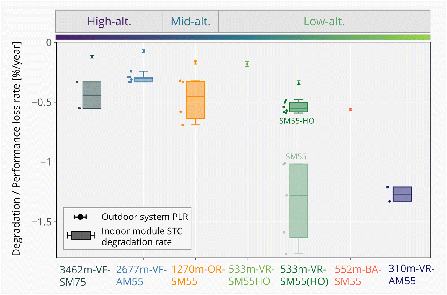 | ||
| Fig. 6 Overview of indoor and outdoor measurement results for all analysed systems. The figure shows: (i) the module degradation rates of Pmp based on indoor I–V measurements (box plots with underlying data points), and (ii) the system PLR calculated from outdoor monitoring data using the multi-YoY method, with 95% CI. Systems are ordered by altitude zones indicated at the top. For the site 533m-VR-SM55(HO), which is composed of 94% SM55-HO modules and 6% SM55 modules, both types are shown for the indoor I–V results. The minority type is displayed in a faded colour for clarity as it is less representative of the system behaviour. | ||
The indoor I–V measurements solely capture the I–V characteristics of a module at STC, providing insights limited to those specific conditions. However, the PLR analysis accounts for a broader range of irradiance and temperature conditions, providing a more comprehensive reflection of real-world performance over the entire monitoring period and the whole system. This approach also captures the influence of spectral variations and the angle of incidence, which are not captured in standard indoor I–V measurements. Since modules may degrade at different rates across irradiance levels – potentially showing different behaviour at low irradiance compared to 1000 W m−2 – discrepancies between indoor I–V results and outdoor PLR findings are expected. Additionally, as previously noted, insufficient maintenance of outdoor monitoring systems can compromise the accuracy of performance evaluations. Specifically, pyranometers used for irradiance measurements, if not periodically calibrated, are prone to sensor drift over time, resulting in deviations in irradiance readings.
At first glance, the data seems to suggest that systems located at lower-altitudes exhibit greater performance changes compared to those at higher-altitudes. However, careful analysis is necessary to avoid drawing premature conclusions from this observed trend. To investigate further, the following sections will delve into specific comparisons of (i) module performance within the same area or altitude zone, as BOM variations or manufacturing differences could be contributing factors; (ii) similar module types situated at different altitudes, to better assess the impact of temperature and climatic stressors in terms of performance changes and degradation paths.
3.2.1.1 Tiergarten West (533m-VR-SM55(HO)): modules SM55 and SM55-HO. Results of the long-term performance analysis based on the outdoor-monitored data for site 533m-VR-SM55(HO) indicate a system PLR −0.34% per year. For the indoor measurements, 12 modules were retrieved: five SM55 modules and seven SM55-HO modules (as a reminder, the system is comprised of 94% SM55-HO modules, and only 6% of the standard SM55 type). Despite sharing the same rooftop and outdoor exposure conditions, the five SM55 modules showed an average of approximately twice as much performance changes in indoor I–V at STC measurements (Fig. 6). The primary cause for these variations appears to be recurring solder bond failures observed in all five modules of this type, resulting in increased series resistance and a decrease in fill factor (FF), visible in the I–V curve and EL image of the SM55 module (Fig. 7). The solder interconnections between the ribbons and the busbars seem to have developed cracks starting at the cell edges and progressing towards the centre of the busbars. This results in darker areas near the cell edges and bright spots at the centre of the ribbons. In some severe cases, solder interconnections between ribbons and busbars appear to have completely cracked, leading to entirely dark areas without bright spots along the ribbons. Similar patterns of recurring solder bond failure in this type of module have been documented in previous studies.51,52 The consistent occurrence of solder bond failures suggests potential inadequacies in production processes and quality control measures. Based on energy dispersive X-ray spectroscopy (EDX) element analysis of the solder interconnection area (Sn–Pb), Han et al.51 suggest that solder interconnection fatigue is caused by repeating temperature cycles,53 coupled with possible chemical corrosion and the formation of intermetallics.
 | ||
| Fig. 7 I–V curves of the reference, SM55, and SM55-HO modules from the 533m-VR-SM55(HO) site, along with EL images taken after approximately 30 years of outdoor operation. The SM55 module exhibits increased series resistance and reduced fill factor due to recurring solder bond failures, visible as dark areas near cell edges and bright spots along the ribbons in the EL images. | ||
Additionally, it was of interest to analyse the BOM of the SM55 and SM55-HO as the label and data sheet did not indicate any difference. The polymeric materials of the modules were first analysed non-destructively using NIR spectroscopy. By analysing the NIR spectra of the entire backsheet stack, the backsheet laminate was identified as Tedlar backsheet with the known composition PVF/PET/PVF for both module types SM55 and SM55-HO. When applying chemometric modelling to all backsheet NIR-spectra, however, some differences between the two module types were detectable. The PCA results show that the scores for the SM55-HO backsheet are clearly separated from those of the SM55 modules, suggesting significant variations in the spectra (Fig. 8a). The variable importance plot of the RDF model did not show contributions to this variations from specific spectral regions. Changes were present across all variables. This suggests that the difference is not due to changes in certain specific functional groups of the backside material, but to a different composition (i.e. additional ingredient). To validate this assumption, samples were cut from the module, cross-sections were prepared, and light and ATR-IR microscopic images were recorded. These images revealed (i) a thicker inner PVF layer in the backsheet SM55-HO compared to SM55 and (ii) the presence of chalk (CaCO3) particles as filler in this inner layer (Fig. 8b). In the SM55 modules of this system (and most other), TiO2 is used as a filler for both PVF layers. The different filling material was used in the inner layer of the backsheet to achieve higher efficiencies with higher internal reflectance – the modules comprising this backsheet type were called SM55-HO (High Output) as reported by ref. 54.
 | ||
| Fig. 8 (a) PCA scores obtained from PCA clustering analysis of the whole NIR spectra, highlighting a clear distinction of the SM55-HO module type. (b) ATR-IR image of the cross-section of the backsheet of a SM55-HO module showing the CaCO3 filler. | ||
3.2.1.2 Möhlin and Tiergarten West (310m-VR-AM55 and 533m-VR-SM55(HO)): modules SM55 and AM55. Recurring solder bond failures, initially identified in EL images of SM55 modules from the 533m-VR-SM55(HO) system, were also observed in the AM55 modules of the 310m-VR-AM55 system, as shown in Fig. 9. These failures similarly contributed to performance degradation of the AM55 modules, confirmed with I–V measurement results in the form of increased series resistance and decreased FF. This results in a median module degradation rate of −1.27% per year (Fig. 6).
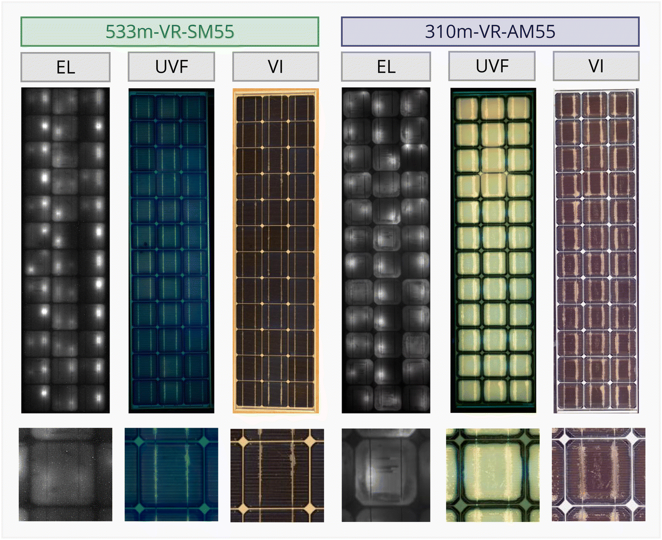 | ||
| Fig. 9 Electroluminescence (EL), ultraviolet-fluorescence (UVF) and visual inspection (VI) images of the modules from the 533m-VR-SM55 and 310m-VR-AM55 systems. | ||
Two major differences between the SM55 and AM55 modules from the 533m-VR-SM55(HO) and 310m-VR-AM55 systems, respectively, were identified through UVF and visual inspection (VI) imaging. In the UVF images, the encapsulant in the AM55 module exhibits a different emission colour and intensity, suggesting potential variations in additives or encapsulant composition (Fig. 9). In the VI images, both module types show delamination of the encapsulant along the ribbons, with the AM55 module displaying more severe delamination compared to the SM55 module. In addition, the AM55 module shows discolouration of the encapsulation material. These modules are the oldest of those examined (manufactured in 1987) and were manufactured before the introduction of UV-stabilisation of EVA for PV applications. The discolouration can be explained by photo-oxidative degradation. Encapsulant quality improved after 1987 by stepwise stabilisation of the polymer with UV-stabilisers and anti-oxidants, thus effectively reducing discolouration. A noticeable lack of discolouration and fluorescence is observed at the cell edges, likely caused by photobleaching, a competing process to the discolouration and fluorescence of EVA in the presence of oxygen permeating through the backsheet.55
3.2.1.3 Mont-Soleil (1270m-OR-SM55). Indoor I–V measurements of four SM55 modules from the 1270m-OR-SM55 system revealed differing module degradation rates. Specifically, two modules exhibited higher loss compared to the other two. As shown in Fig. 10a, all modules exhibited a reasonable decrease in Isc, yet they have different FF trends: two modules experienced a reduction in FF, while the remaining two showed no significant change.
 | ||
| Fig. 10 (a) Degradation rates of the module I–V parameters (indoor) and (b) EL images of four modules from the 1270m-OR-SM55 system. (c) ATR-IR image, shown as an inset in the figure, highlights the dark area of Module 3 with compare-correlation analysis with the IR spectrum of the unaged adhesive. | ||
EL imaging revealed that modules with higher FF loss exhibited dark areas in some cells, whereas no dark areas were observed in the other modules (Fig. 10b). Encapsulation materials, extracted destructively from Module 1 and from both the dark and non-dark areas of Module 3, were analysed for their degradation product content by thermo-desorption GC-MS. The acetic acid detected in EVA from the dark areas of Module 3 was approximately twice the amount found in the non-dark areas of the same module (Fig. 11a). In fact, the acetic acid concentration in the non-dark areas of Module 3 was similar to that of the less degraded Module 1 (not shown). This suggests a locally higher rate of degradation and acetic acid formation in the dark areas likely due to locally higher temperatures. Acetic acid is known to cause corrosion of the silver (Ag) fingers and reduce the conductivity of the Ag finger,56–58 thereby increasing the contact resistance between the Ag and Si, which in turn contributes to the observed decrease in FF and dark areas in EL images.59
 | ||
| Fig. 11 (a) Amount of acetic acid detected in the EVA with TD-GC/MS. (b) UVF images of the modules after 30 years of outdoor exposure, alongside a UVF image of a non-weathered reference SM55 module. (c) ATR-IR images of the cross-sections of backsheets after compare-correlation with the IR spectrum of the unaged adhesive (high correlation = red). | ||
To further investigate localised stress and material degradation in the polymer layers, ATR-IR microscopic imaging was performed and analysed using compare-correlation techniques with the original material. Particular attention was given to the adhesive layers (∼5–7 μm) between the PVF and PET layers, as these are known to be indicators of the thermal stress impact on the laminate.43 In the unaged reference module, the adhesive layer is well-defined, with a thickness of approximately 5–7 μm, and exhibits a high correlation with the original adhesive spectrum (Fig. 11c, where red areas indicate high spectral accordance). However, in the dark regions observed in the EL image of Module 3, the adhesive layers appear indistinct, with the outer layer degrading almost completely (Fig. 10c). In addition to the corrosion of the Ag fingers leading to dark areas in the EL images, this additional degradation route also suggests significantly higher thermal stress in these areas.
UVF images of the modules are compared, including the unweathered SM55 reference module (Fig. 11b). As expected, the encapsulant of the reference module shows no clear fluorescence emission, as it has not been exposed to environmental stressors such as temperature and irradiance. In contrast, modules from both 533m-VR-SM55(HO) and 2677m-VF-AM55 systems show clear fluorescence of the polymer encapsulant. As discussed in Section 3.1, although modules in both systems were exposed to approximately the same irradiation dose, the SM55-HO modules from 533m-VR-SM55(HO) experienced higher operating temperatures. Increased thermal stress accelerates the formation of degradation products in the encapsulation material that can be associated with fluorescence effects.60
To analyse potential encapsulant degradation on a deeper level, NIR spectra of the EVA encapsulants were examined by comparing the module from the low-altitude system (533m-VR-SM55(HO)) with the module from the high-altitude system (2677m-VF-AM55). The spectra were analysed with RDF as it can indicate the spectral regions where differences or ageing induced changes occur (with the variable importance plot). It shows differences in the spectral region 5880–5930 cm−1, which corresponds to overtones of aliphatic C–H stretching vibrations, most likely of –CH3 groups. The CH3 groups are present in the acetate side groups of EVA, which can be split off as acetic acid. So the analysis indicates a change in the acetic acid content. More detailed destructive analysis of the EVA using TD-GC/MS underlined these assumptions as they reveal higher acetic acid content in the low-altitude modules than in the high-altitude modules (Fig. 11a). As discussed in Section 3.2.1, the acetic acid produced can react with the Ag and lead (Pb) in the cell fingers and solder of the connectors, causing corrosion and poor electrical conductivity, resulting in cell degradation performance losses.
To better understand the relationship between module temperature, electrical and material degradation, the material changes of the backsheet components of the modules installed in the different altitude zones were analysed in more detail. NIR spectra of the backsheets of the various modules were recorded and compared using PCA and RDF. The PCA results show different clusters for the high and low-altitude systems of the same SM55 module type (Fig. 8a). In order to analyse the origin of this variation, RDF was performed, including the creation of a variable importance plot. It shows the most pronounced spectral differences in the region 5170–5280 cm−1, which corresponds to an overtone of a stretching vibration of carbonyl groups. This indicates a change in the PET core layer and/or the adhesive (polyurethane-based). The most significant difference was observed in the spectra of the backsheet from the low-altitude systems compared to both the reference and high altitude systems.
As described earlier, the status of the adhesive layers within the backsheet laminate can serve as indicators of thermally induced ageing phenomena within the backsheet. Therefore, ATR-IR images of the cross-sections of the aged backsheets were analysed by comparing them to the IR spectrum of the original, unaged adhesive. Results show that the adhesive layer remains intact in the modules from high and mid-altitude sites, which experience lower thermal stress (3462m-VF-SM75, 2677m-VF-AM55, and 1270m-OR-SM55), whereas it degrades in the samples from the low-altitude site 533m-VR-SM55(HO) (Fig. 11c). Voronko et al. have described this phenomenon of adhesive degradation in their detailed analysis of backsheets after various stress impacts.43 Previous work has also shown that the degradation of the connecting layers in the backsheet laminate results in an increased water vapour permeation rate and a higher tendency for delamination.61 Consequently, this is likely to lead to increased corrosion on the cell or interconnectors, which could explain the increased electrical degradation.
4 Discussion
4.1 Impact of climate and environmental stressors
The threefold analysis – weather data, long-term monitoring and indoor laboratory measurements – highlights significant correlations between climatic conditions and the degradation of PV modules, excluding the uncertainties due to potential BOM variations or manufacturing issues. These findings are consistent with earlier studies on the impact of operating conditions on PV system reliability.9,11,26,60 Systems installed in lower altitude zones experience higher operating temperatures, translating to higher levels of thermal and thermomechanical stress. This is exacerbated in the case of the building-applied mounting configuration, which reaches the highest observed module temperatures of nearly 80 °C. This thermal stress and frequent temperature cycling impacts system performance and material stability, with EVA degradation (acetic acid formation, high UVF) and adhesive degradation within the backsheet laminate. These temperature induced material ageing effects could be further confirmed through non-destructive material analysis (NIR spectroscopy and various imaging techniques), and destructive analysis with TD GC/MS and ATR-IR imaging on cross sections. The degradation product acetic acid in the encapsulant acts as precursor to electrical performance losses due to increased corrosion on the solar cell surface – specifically the grid fingers and solder-components – and reduced conductivity thereof.High-altitude systems, although subjected to high radiation exposure (1400 W m−2 in plane of array) and larger temperature fluctuations between day and night (up to 80 °C diurnal temperature variation), experience lower thermal stress which is presumably the reason for slower degradation and thus lower performance loss rates. However, one has to keep in mind that high-altitude PV-free-standing and roof-installations have to face harsh environmental conditions with increased probability of extreme weather events like heavy snow fall, strong winds and or hail and ice events which can cause catastrophic failures on modules and mounting structures.11 Therefore, site selection is an important topic for alpine installations. These findings highlight the need to adapt PV module and system design to the specific environmental conditions, especially in regions with extreme temperature or radiation profiles. Furthermore, the importance of PV-system monitoring and understanding environmental stresses to ensure long-term reliability has to be stated.
4.2 Impact of module design and BOM
Despite being from the same product family, significant differences in degradation trends were observed between the module types, partly depending on the year of production. This was especially decisive for the quality of the EVA encapsulant which was in its implementation and optimisation phase as an encapsulant for PV modules in the late 1980s and early 1990s. The degradation patterns of the modules manufactured before 1987, such as the AM55 (installed in the site 310m-VR-AM55, Möhlin), further underscore the importance of encapsulant quality. The absence of UV stabilisers in early EVA formulations resulted in yellowing and delamination, which were significantly mitigated in later designs (1992 and 1993). These findings highlight the critical role of BOM and manufacturing quality in determining module longevity and degradation rates.Modifications to the inner layer of the Tedlar backsheet were implemented to increase reflectivity to the cells, thereby enhancing power output. This “ultra-white” Tedlar backsheet was utilised in the SM55-HO modules installed at one site (533m-VR-SM55HO, Tiergarten East). On the West side of the same location (533m-VR-SM55(HO)), both SM55 and SM55-HO module types were installed, enabling a direct performance comparison. The SM55-HO modules exhibited superior performance in this particular system, attributed to improved interconnection processes and the thicker backsheet with calcium carbonate fillers, as identified by material analysis. In contrast, the SM55 modules of this system showed solder bond failures and increased series resistance, underscoring manufacturing inconsistencies and the lack of established production standards of the 1980s and 1990s. Over time, however, TiO2 emerged as the standard inorganic filler for Tedlar backsheets.
4.3 Evolution of PV module design: a historical perspective
The structure and BOM of the modules investigated in this study reflect a relatively modern design that would become standard for PV modules for decades to come. Over the past 30 years, solar cell and module technologies evolved steadily until the disruptive advancements that began around 2020 (Table A.1, ESI).†Most degradation paths observed in advanced solar cells today (e.g., PERC, TOPCon, and SHJ) are not present in the Al-BSF solar cells analysed in this study. The Al-BSF cells likely have a heavily doped front side with little to no surface passivation and a short bulk carrier lifetime. In contrast, modern, optimised cell designs feature advanced surface passivation and longer bulk lifetimes that allow silicon bulk to reach its higher potential.62,63 However, these improvements also make the cells more vulnerable to degradation mechanisms, such as external ion migration, bond-breaking at the silicon interfaces or defect formation in the bulk silicon. As a result, while Al-BSF cells exhibit lower efficiency, their simpler design makes them more resilient to additional defects that may form at the silicon interfaces, in the bulk, or within the space charge region.
Given the critical role of encapsulants in ensuring long-term PV module performance,6,7 this work suggests that EVA formulations from the early 1990s show excellent stability, particularly in temperate climates. EVA has remained the dominant encapsulant material for terrestrial PV, although polyolefin (PO) encapsulants have gained popularity recently, particularly for TOPCon bifacial modules with glass/glass structures.
The reliability and durability of the studied modules are remarkable, with annual degradation rates below −0.6% in most cases, even after more than 30 years of operation. This resilience is attributed to design choices such as thicker silicon wafers, robust polymer backsheets, and sturdy aluminum frames (present in all but one system). In contrast, modern PV modules prioritise higher efficiencies and reduced costs, often using thinner materials and lighter designs, which may compromise long-term reliability. The rapid technological evolution and changes in module design and material selection over the last five years could potentially undermine the performance seen in older systems. Nevertheless, these older modules demonstrate that solar PV is a stable and reliable power generation technology. Insights from these historical designs suggest that robust material choices can enhance the longevity of modern modules. Balancing efficiency with durability is critical as the industry enters terawatt scale to meet global energy demands.
4.4 Limitations and future work
This study provides valuable insights into the performance of PV systems; however, several limitations and areas for future research should be considered. The results are representative of Central European temperate climates, including alpine regions at high-altitude. However, the findings may not be directly applicable to other climate types such as tropical or arid regions, necessitating further investigation and dedicated studies.Although the study relies solely on on-site ground measurements, which have lower uncertainty than satellite-derived data, potential errors due to sensor drift, bias, or data logging issues over time cannot be entirely ruled out. Comprehensive outlier filtering and error correction techniques were applied to mitigate these effects as much as possible. Additionally, the use of nameplate values, which were determined with lower accuracy and precision in the late 1980s and early 1990s as the initial I–V values for the modules, undoubtedly introduces uncertainty in both the module degradation rate and PR calculations.
NIR spectroscopy, used as a non-destructive material analysis method in this study, only provided initial insights into material degradation. Further development of chemometric analysis of NIR measurements on PV modules is necessary to provide more accurate predictions of polymer degradation, thereby enhancing the understanding of material longevity.
Despite these limitations, the extensive analysis of these PV systems, combining data-driven and laboratory-based approaches, offers valuable lessons to be learned from these unique plants. Future work could include fault detection and diagnosis analysis of the AC or DC data available, which could be correlated to field measurements and further material characterisation.
5 Conclusions
This study provides comprehensive insights into the long-term performance and durability of PV modules deployed for over 20–30 years across six PV installations in varying altitude zones/climatic conditions in Switzerland, making these plants a valuable and unique asset for long-term PV reliability research.The results highlight the exceptional reliability of PV modules manufactured in the late 1980s and early 1990s, with system PLRs averaging just −0.24 ± 0.16% per year, significantly below the typical literature reported range of −0.75% to −1% per year for crystalline silicon PV systems. Through indoor laboratory measurements, it could be shown that most of the modules retained over 80% of their initial nominal power after 30–35 years in the field – exceeding the typical industry warranty threshold of 80% after 25 years – and demonstrating the potential for service lifetimes exceeding 50 years under temperate climate conditions.
Modules installed in high-altitude climates benefited from lower thermal stress, with module temperatures up to 20 °C lower than those in low-altitude zones. This translated into reduced material ageing and a lower average PLR of −0.11% per year at high altitude, compared to −0.35% per year at low altitude. Material analyses confirmed that higher thermal stress at low altitudes led to increased encapsulant degradation, higher acetic acid formation, and adhesive degradation in the backsheet, all contributing to localised corrosion and elevated performance losses. In contrast, modules in cooler high-altitude environments exhibited fewer signs of chemical and mechanical degradation.
Importantly, the study identified the BOM as the most critical factor influencing PV module longevity. Despite all modules belonging to the same product family, variations in encapsulant quality, filler materials, and manufacturing processes resulted in significant differences in degradation rates. Early-generation encapsulants without UV stabilisation showed accelerated ageing, while later module designs with optimised backsheets and improved production quality demonstrated outstanding long-term stability.
The robustness of these early modules – featuring glass/foil structures, EVA encapsulants, Tedlar backsheets, thick silicon wafers, and robust frames – offers valuable lessons for modern PV technology. While today's modules focus on higher efficiencies and cost reductions, which may come with increased susceptibility to defects, this study underscores the importance of balancing these priorities with proven durability strategies to ensure long-term reliability.
As the PV industry advances into the terawatt age, insights from long-term field data and material analyses remain essential for guiding improvements in module design, manufacturing standards, and sustainability. Ultimately, well-designed modules and systems have the potential to operate well beyond conventional warranty periods, contributing to lower LCOE, a reduced carbon footprint, and extended service lifetimes for PV systems.
Data availability
The data for this article, including near-infrared spectroscopy (NIR) measurements of encapsulants and backsheets, nominal IV parameters (maximum power, short-circuit current, open-circuit voltage, maximum power current, maximum power voltage, and fill factor), measured IV parameters after approximately 30 years of outdoor monitoring of the modules, electroluminescence images, and IV curves of the three modules presented in the article, are archived and available in Zenodo with the DOI: https://doi.org/10.5281/zenodo.14524158. The Python code for the multi-YoY (year-on-year) method used for outdoor data analysis is shared in a GitHub repository archived in Zenodo with the DOI: https://doi.org/10.5281/zenodo.11562417. Outdoor data can be requested by contacting Prof. Dr Christof Bucher at E-mail: christof.bucher@bfh.ch.Author contribution
Ebrar Özkalay: conceptualisation, methodology, investigation, data curation, formal analysis, visualisation, writing – original draft, writing – review & editing. Hugo Quest: conceptualisation, methodology, investigation, data curation, formal analysis, visualisation, writing – original draft, writing – review & editing. Anika Gassner: conceptualisation, methodology, investigation, data curation, formal analysis, visualisation, writing – original draft, writing – review & editing. Alessandro Virtuani: conceptualisation, writing – review & editing, supervision. Gabriele C. Eder: conceptualisation, formal analysis, writing – review & editing, upervision. Stefanie Vorstoffel: writing – review & editing. Claudia Buerhop-Lutz: writing – review & editing. Gabi Friesen: writing – review & editing. Christophe Ballif: writing – review & editing. Matthias Burri: resources, data curation, writing – review & editing. Christof Bucher: resources, data curation, writing – review & editing.Conflicts of interest
There are no conflicts of interest to declare.Acknowledgements
The work of SUPSI and OFI was supported by Climate and Energyfond processed by the Austrian Research Promotion Agency (FFG) and the Swiss Federal Office of Energy (SFOE) within the Solar-Era.net project PV-DETECT, under agreement numbers FO999897441 and SI/502484-1, respectively. The work of EPFL and CSEM was supported by the Swiss Federal Office of Energy (SFOE) under grant agreement number SI/502904-01 (ASSURed-PV project). The authors wish to express their sincere gratitude to Prof Dr Heinrich Häberlin, Thomas Schott, Prof Urs Muntwyler, Christian Renken, Luciano Borgna, Philipp Schärf, Monika Jost, Daniel Gfeller, and David Joss for their pivotal contributions and vision. Their efforts, together with the teams at Bern University of Applied Sciences (BFH), Société Mont-Soleil, and High Altitude Research Station Jungfraujoch and Gornergrad (HFSJG) were instrumental in carrying out the extensive measurements campaign of SM55/AM55 modules. This work reflects the contributions of at least three generations of researchers and PV enthusiasts who have been dedicated to this project over the past three decades. It highlights the ongoing effort to “hand over the baton” to the next generation, ensuring the continuity of this important research. The long-term data collection and analysis were made possible thanks to the expertise, commitment, and collaboration of everyone involved. We are grateful to all contributors for their valuable support and foresight. Most of the represented institutions (SUPSI, OFI, CSEM, BFH) are active members and collaborate in the IEA-PVPS (international Energy Agency – Photovoltaic Power Systems Programme) Task 13 (Reliability and Performance of Photovoltaic Systems).References
- G. Masson, M. de l'Epine and I. Kaizuka, Trends in PV Applications 2024, 2024 Oct, Available from, https://iea-pvps.org/trends_reports/trends-in-pv-applications-2024/.
- A. Virtuani and L. Morganti, Profitability of Solar Photovoltaic Projects: A Sensitivity Analysis of Performance Loss Curves and Operation and Maintenance Expenses, Sol. RRL, 2023, 7(8), 2200663, DOI:10.1002/solr.202200663.
- A. Virtuani, A. Borja Block, N. Wyrsch and C. Ballif, The carbon intensity of integrated photovoltaics, Joule, 2023, 7(11), 2511–2536 CrossRef CAS . Available from: https://www.sciencedirect.com/science/article/pii/S2542435123004002.
- IRENA, Renewable Power Generation Costs in 2023, International Renewable Energy Agency, Abu Dhabi, 2024, Available from: https://www.irena.org/Publications/2024/Sep/Renewable-Power-Generation-Costs-in-2023.
- J. Denz, J. Hepp, C. Buerhop, B. Doll, J. Hauch and C. J. Brabec, et al., Defects and performance of Si PV modules in the field – an analysis, Energy Environ. Sci., 2022, 15, 2180–2199 Search PubMed.
- A. Virtuani, M. Caccivio, E. Annigoni, G. Friesen, D. Chianese and C. Ballif, et al., 35 years of photovoltaics: Analysis of the TISO-10-kW solar plant, lessons learnt in safety and performance—Part 1, Prog. Photovoltaics Res. Appl., 2019, 27(4), 328–339 CrossRef.
- E. Annigoni, A. Virtuani, M. Caccivio, G. Friesen, D. Chianese and C. Ballif, 35 years of photovoltaics: Analysis of the TISO-10-kW solar plant, lessons learnt in safety and performance—Part 2, Prog. Photovoltaics Res. Appl., 2019, 27(9), 760–778 CrossRef.
- J. Ascencio-Vásquez, K. Brecl and M. Topič, Methodology of Köppen-Geiger-Photovoltaic climate classification and implications to worldwide mapping of PV system performance, Sol. Energy, 2019, 191, 672–685 CrossRef . Available from: https://www.sciencedirect.com/science/article/pii/S0038092X19308527.
- M. Koehl, M. Heck and S. Wiesmeier, Categorization of weathering stresses for photovoltaic modules, Energy Sci. Eng., 2018, 6(2), 93–111 Search PubMed.
- B. Adothu, S. Kumar, J. J. John, G. Oreski, G. Mathiak and B. Jäckel, et al., Comprehensive review on performance, reliability, and roadmap of c-Si PV modules in desert climates: A proposal for improved testing standard, Prog. Photovoltaics Res. Appl., 2024, 32(8), 495–527 CrossRef.
- D. C. Jordan, K. Perry, R. White and C. Deline, Extreme Weather and PV Performance, IEEE J. Photovoltaics, 2023, 13, 830–835 Search PubMed.
- M. Halwachs, L. Neumaier, N. Vollert, L. Maul, S. Dimitriadis and Y. Voronko, et al., Statistical evaluation of PV system performance and failure data among different climate zones, Renewable Energy, 2019, 139, 1040–1060 Search PubMed . Available from: https://linkinghub.elsevier.com/retrieve/pii/S0960148119303003.
- L. El Boujdaini, C. Bucher, E. Özkalay, A. Mezrhab, M. Burri, M. Caccivio, et al., Analysis of non-linear long-term degradation of PV systems, 8th World Conference on Photovoltaic Energy Conversion (WCPEC-8), 2022 Search PubMed.
- T. Schott, F. Kuonen, U. Muntwyler and E. Schuepbach, Degradation of photovoltaic systems based on long-term measurements and laboratory tests, in Proceedings of EuroSun 2018, International Solar Energy Society, Rapperswil, CH, 2018. p. 1–7, Available from: http://proceedings.ises.org/citation?doi=eurosun2018.02.07 Search PubMed.
- E. Schuepbach, U. Muntwyler, M. Jost and T. Schott, Long-Term Performance Of Swiss Photovoltaic (PV) Installations, 29th European Photovoltaic Solar Energy Conference and Exhibition, 2014 Search PubMed.
- H. E. Beck, T. R. McVicar, N. Vergopolan, A. Berg, N. J. Lutsko and A. Dufour, et al., High-resolution (1 km) Köppen-Geiger maps for 1901–2099 based on constrained CMIP6 projections, Sci. Data, 2023, 10(1), 724 CrossRef PubMed . Publisher: Nature Publishing Group. Available from: https://www.nature.com/articles/s41597-023-02549-6.
- United Press International, Siemens accuses ARCO of fraud in sale of solar business – UPI Archives, 1993, Available from: https://www.upi.com/Archives/1993/03/01/Siemens-accuses-ARCO-of-fraud-in-sale-of-solar-business/9972730962000/.
- S. G. Siemens. Solarmodul Sm55/SM50;.
- J. D. Wood, T. J. Griffis and J. M. Baker, Detecting drift bias and exposure errors in solar and photosynthetically active radiation data, Agric. For. Meteorol., 2015, 206, 33–44 CrossRef . Available from: https://www.sciencedirect.com/science/article/pii/S0168192315000647.
- Copernicus Atmosphere Monitoring Service (CAMS) Atmosphere Data Store (ADS), CAMS solar radiation time-series, 2024, Available from: https://www.soda-pro.com/web-services/radiation/cams-radiation-service.
- M. Kottek, J. Grieser, C. Beck, B. Rudolf and F. Rubel, World Map of the Köppen-Geiger climate classification updated, Meteorol. Z., 2006, 15(3), 259–263 CrossRef PubMed : http://www.schweizerbart.de/papers/metz/detail/15/55034/World_Map_of_the_Koppen_Geiger_climate_classificat?af=crossref.
- D. Jordan, C. Deline, M. Deceglie, T. Silverman and W. Luo, 2019 IEEE 46th Photovoltaic Specialists Conference (PVSC), PV Degradation – Mounting & Temperature, 2019, pp. 0673–0679, DOI:10.1109/PVSC40753.2019.8980767.
- A. Gok, E. Özkalay, G. Friesen and F. Frontini, The Influence of Operating Temperature on the Performance of BIPV Modules, IEEE J. Photovoltaics, 2020, 10(5), 1371–1378 Search PubMed.
- A. Virtuani and D. Strepparava, Modelling the performance of amorphous and crystalline silicon in different typologies of building-integrated photovoltaic (BIPV) conditions, Sol. Energy, 2017, 146, 113–118 CrossRef CAS . Available from: https://linkinghub.elsevier.com/retrieve/pii/S0038092X17301287.
- N. Bosco, T. J. Silverman and S. Kurtz, Climate specific thermomechanical fatigue of flat plate photovoltaic module solder joints, Microelectron. Reliab., 2016, 62, 124–129 CrossRef CAS.
- N. Bosco, T. J. Silverman and S. Kurtz, The Influence of PV Module Materials and Design on Solder Joint Thermal Fatigue Durability, IEEE J. Photovoltaics, 2016, 6(6), 1407–1412 Search PubMed.
- H. Quest, A. Fairbrother, C. Ballif and A. Virtuani, Towards a quantification of thermal and thermomechanical stress for modules in building-integrated photovoltaics configurations, Prog. Photovoltaics Res. Appl., 2023, 33, 64–75 CrossRef.
- IEC, IEC 63092-2:2020 – Photovoltaics in buildings – Part 2: Requirements for building-integrated photovoltaic systems, 2020, Available from: https://webstore.iec.ch/en/publication/32329.
- E. Özkalay, G. Friesen, M. Caccivio, P. Bonomo, A. Fairbrother and C. Ballif, et al., Operating Temperatures and Diurnal Temperature Variations of Modules Installed in Open-Rack and Typical BIPV Configurations, IEEE J. Photovoltaics, 2022, 12(1), 133–140 Search PubMed . Number: 1. Available from: https://ieeexplore.ieee.org/document/9576676/.
- A. Gok, E. Ozkalay, G. Friesen and F. Frontini, Power Loss Modes of Building-Integrated Photovoltaic Modules: An Analytical Approach Using Outdoor I-V Curves, IEEE J. Photovoltaics, 2021, 11(3), 789–796 Search PubMed.
- M. D. Kempe, D. Holsapple, K. Whitfield and N. Shiradkar, Standards development for modules in high temperature micro-environments, Prog. Photovoltaics Res. Appl., 2021, 29(4), 445–460 CrossRef.
- M. Owen-Bellini, Thermomechanical degradation mechanisms of silicon photovoltaic modules, Phd thesis, Loughborough University, 2017, Available from: https://figshare.com/articles/thesis/Thermomechanical_degradation_mechanisms_of_silicon_photovoltaic_modules/9539651/1 Search PubMed.
- F. Guo, V. Do, R. Cooper, Y. Huang, P. Zhang and J. Ran, et al., Trends of temperature variability: Which variability and what health implications?, Sci. Total Environ., 2021, 768, 144487 Search PubMed.
- H. Quest, C. Ballif and A. Virtuani, Multi-Annual Year-on-Year: Minimising the Uncertainty in Photovoltaic System Performance Loss Rates, Prog. Photovoltaics Res. Appl., 2025, 33, 411–424 CrossRef.
- H. Quest, C. Ballif and A. Virtuani, Intrinsic performance loss rate: Decoupling reversible and irreversible losses for an improved assessment of photovoltaic system performance, Prog. Photovoltaics Res. Appl., 2024, 32(11), 774–789 CrossRef . Available from: https://onlinelibrary.wiley.com/doi/abs/10.1002/pip.3829.
- M. Theristis, K. Anderson, J. Ascencio-Vasquez and J. S. Stein, How Climate and Data Quality Impact Photovoltaic Performance Loss Rate Estimations, Sol. RRL, 2024, 8(2), 2300815 CrossRef.
- D. C. Jordan, C. Deline, S. R. Kurtz, G. M. Kimball and M. Anderson, Robust PV Degradation Methodology and Application, IEEE J. Photovoltaics, 2018, 8(2), 525–531 Search PubMed.
- E. Hasselbrink, M. Anderson, Z. Defreitas, M. Mikofski, Y. C. Shen, S. Caldwell, et al., Validation of the PVLife model using 3 million module-years of live site data, in 2013 IEEE 39th Photovoltaic Specialists Conference (PVSC), 2013, pp. 0007–0012 Search PubMed.
- IEC, IEC 61215-2: 2021 Terrestrial photovoltaic (PV) modules – Design qualification and type approval – Part 2: Test procedures, 2021, Available from: https://webstore.iec.ch/en/publication/61350.
- E. Datalab, DataLab – Statistics Package, Available from: https://datalab.epina.at/.
- I. T. Jolliffe and J. Cadima, Principal component analysis: a review and recent developments, Philos. Trans. R. Soc., A, 2016, 374(2065), 20150202, DOI:10.1098/rsta.2015.0202.
- L. Breiman, Random Forests, Mach. Learn., 2001, 45(1), 5–32, DOI:10.1023/A:1010933404324.
- Y. Voronko, B. S. Chernev and G. C. Eder, Spectroscopic Investigations on Thin Adhesive Layers in Multi-Material Laminates, Appl. Spectrosc., 2014, 68(5), 584–592, DOI:10.1366/13-07291.
- M. Kontges, A. Morlier, G. Eder, E. Fleis, B. Kubicek and J. Lin, Review: Ultraviolet Fluorescence as Assessment Tool for Photovoltaic Modules, IEEE J. Photovoltaics, 2020, 10, 616–633, DOI:10.1109/jphotov.2019.2961781.
- D. C. Jordan, T. J. Silverman, B. Sekulic and S. R. Kurtz, PV degradation curves: non-linearities and failure modes, Prog. Photovoltaics Res. Appl., 2017, 25(7), 583–591 CrossRef.
- S. Lindig, A. Louwen, D. Moser and M. Topic, New PV Performance Loss Methodology Applying a Self-Regulated Multistep Algorithm, IEEE J. Photovoltaics, 2021, 11(4), 1087–1096 Search PubMed.
- D. Jordan, K. Anderson, K. Perry, M. Muller, M. Deceglie and R. White, et al., Photovoltaic fleet degradation insights, Prog. Photovoltaics Res. Appl., 2022, 30(10), 1166–1175 CrossRef.
- D. C. Jordan, N. Haegel and T. M. Barnes, Photovoltaics module reliability for the terawatt age, Prog. Energy, 2022, 4(2), 022002 Search PubMed.
- M. Theristis, J. Stein, C. Deline, D. Jordan, C. Robinson and W. Sekulic, et al., Onymous early-life performance degradation analysis of recent photovoltaic module technologies, Prog. Photovoltaics Res. Appl., 2022, 31, 149–160 Search PubMed.
- A. Louwen, S. Lindig, G. Chowdhury and D. Moser, Climate- and Technology-Dependent Performance Loss Rates in a Large Commercial Photovoltaic Monitoring Dataset, Sol. RRL, 2024, 8(5), 2300653 Search PubMed.
- H. Han, X. Dong, H. Lai, H. Yan, K. Zhang and J. Liu, et al., Analysis of the Degradation of Monocrystalline Silicon Photovoltaic Modules after Long-Term Exposure for 18 Years in a Hot-Humid Climate in China, IEEE J. Photovoltaics, 2018, 5(8), 806–812 Search PubMed.
- J. Wohlgemuth, T. Silverman, D. C. Miller, P. McNutt, M. Kempe and M. Deceglie, Evaluation of PV module field performance, in IEEE 42nd Photovoltaic Specialist Conference (PVSC), IEEE, 2015 Search PubMed.
- U. Itoh, M. Yoshida, H. Tokuhisa, K. Takeuchi and Y. Takemura, Solder joint failure modes in the conventional crystalline si module, Energy Procedia, 2014, 55, 464–468 Search PubMed.
- T. Jester, Personal communication to A.V, 2024.
- F. J. Pern and S. H. Glick, Fluorescence analysis as a diagnostic tool for polymer encapsulation processing and degradation, AIP Conf. Proc., 1994, 306(1), 573–585 Search PubMed.
- A. W. Czanderna and F. J. Pern, Encapsulation of PV modules using ethylene vinyl acetate copolymer as a pottant: A critical review, Sol. Energy Mater. Sol. Cells, 1996, 43(2), 101–181 Search PubMed.
- M. D. Kempe, G. J. Jorgensen, K. M. Terwilliger, T. J. McMahon, C. E. Kennedy and T. T. Borek, Acetic acid production and glass transition concerns with ethylene-vinyl acetate used in photovoltaic devices, Sol. Energy Mater. Sol. Cells, 2007, 91, 315–329 CrossRef CAS.
- B. Ketola and A. Norris, Degradation Mechanism Investigation of Extended Damp Heat Aged PV Modules, in 26th European Photovoltaic Solar Energy Conference, 2011 Search PubMed.
- W. Oh, S. Kim, S. Bae, N. Park, Y. Kang and H. S. Lee, et al., The degradation of multi-crystalline silicon solar cells after damp heat tests, Microelectron. Reliab., 2014, 54, 2176–2179 CrossRef CAS.
- E. Özkalay, A. Virtuani, G. Eder, Y. Voronko, P. Bonomo and M. Caccivio, et al., Correlating long-term performance and aging behaviour of building integrated PV modules, Energy Build., 2024, 316, 114252 CrossRef . Available from: https://linkinghub.elsevier.com/retrieve/pii/S0378778824003682.
- Y. Voronko, G. C. Eder, M. Knausz, G. Oreski, T. Koch and K. A. Berger, Correlation of the loss in photovoltaic module performance with the ageing behaviour of the backsheets used, Prog. Photovoltaics Res. Appl., 2015, 23(11), 1501–1515, DOI:10.1002/pip.2580.
- G. Hahn, Review of Induced Degradation Phenomena Affecting PV Modules, 38th European Photovoltaic Solar Energy Conference and Exhibition, 2021, pp. 568–572 Search PubMed.
- M. Aghaei, A. Fairbrother, A. Gok, S. Ahmad, S. Kazim and K. Lobato, et al., Review of degradation and failure phenomena in photovoltaic modules, Renewable Sustainable Energy Rev., 2022, 159, 112160 CrossRef CAS.
Footnotes |
| † Electronic supplementary information (ESI) available. See DOI: https://doi.org/10.1039/d4el00040d |
| ‡ Equally contributing authors. |
| This journal is © The Royal Society of Chemistry 2025 |