DOI:
10.1039/D5EB00045A
(Paper)
EES Batteries, 2025,
1, 450-467
Mechanics-modified equilibrium potential for linear-elastic electrode materials†
Received
5th March 2025
, Accepted 16th April 2025
First published on 28th April 2025
Abstract
There is inconsistency in how the mechanics-modified equilibrium potential is constructed in the literature for solid-state batteries; both hydrostatic and surface-normal stresses have been employed. We attempt to resolve this by deriving equilibrium-potential expressions for a linear-elastic electrode material deposited on a solid electrolyte under three different loading conditions: (1) working electrode under out-of-plane uniaxial compression, (2) solid electrolyte under in-plane uniaxial compression, and (3) solid electrolyte under pure shear. Our analysis, which starts from full tensorial stress and strain descriptions specifically at the isothermal electrode/electrolyte interface, indicates that the hydrostatic stress is a more general and widely applicable choice. The deviatoric contribution that the full tensor treatment considers is shown to be practically negligible, making the hydrostatic stress an excellent approximation for battery-modeling purposes. Furthermore, our analytical expressions depend on the mechanical properties of the constituent electrode and electrolyte (i.e., their elastic moduli and Poisson's ratios); no such explicit dependence has been fleshed out previously for experimentally relevant systems. COMSOL simulation results are provided to verify the validity of the analytical expressions, and correction factors are introduced to extend their use to more practical systems. Finally, a cantilever-beam experiment is suggested to help validate our proposed use of the hydrostatic stress more explicitly.
Broader context
Solid-state batteries (SSBs) have been hailed as next-generation battery technology because of their potential to overcome many limitations that conventional lithium-ion batteries have. Nevertheless, they are not yet at the commercial-production stage, and further research and development are required for the mass-market rollout. The development of this new technology motivates the fundamental understanding of the processes that take place during charging and discharging, which modeling can provide. An important consideration when modeling SSBs is the interplay between mechanics and electrochemistry. Typical solid-electrolyte and electrode materials are comparatively stiff, and high stresses are expected during battery operation because of the active-material volume changes. Stress is a tensor quantity composed of hydrostatic (volume change) and deviatoric (shape change) parts, both of which should contribute to the Gibbs free energy. A rigorous Gibbs-free-energy construction is important because it governs the thermodynamic, kinetic, and transport aspects of the system. In this work, equilibrium-potential expressions are derived under different experimentally achievable loading conditions based on a framework that incorporates full stress and strain tensors. It is anticipated that our careful mechanical analysis underscores the role and importance of solid mechanics in SSB modeling.
|
1 Introduction
Solid-state batteries (SSBs) have received heightened attention in recent years because of their high energy densities and potential for alleviating safety concerns associated with highly flammable carbonate-based liquid electrolytes.1–5 Unfortunately, employing solid electrolytes (SE) instead of liquid electrolytes adds a layer of complexity to the design and evaluation of SSBs, since this necessitates mechanical considerations. The expansion and contraction of the electrode active materials due to the alkali–metal-ion (typically lithium or sodium) insertion and extraction induce significant stresses in intercalation electrodes and may affect the battery electrochemical behaviors.6–10 The importance of electrochemical–mechanical considerations equally applies to systems involving metallic anodes, where volume changes would be most pronounced due to the direct metal stripping/plating.11–14 Nevertheless, more traditional electrochemical theories rarely deal with all-solid systems and the absence of well-accepted formalisms results in inconsistencies among SSB models. In particular, the Gibbs free energy G in the conventional format is an inadequate energy descriptor for all-solid systems because the mechanical contribution to G is usually limited to the pressure–volume (pV) work, which pertains to volume changes associated with a single mechanical variable, i.e., pressure. However, a tensor treatment is necessary for all-solid systems to fully describe their mechanical states, and there is no underpinning footing as to why deviatoric stresses and strains should be excluded when calculating their energy contents. This lack of mechanical rigor was pointed out by Goyal and Monroe,15 who constructed a framework capable of evaluating thermodynamic and transport phenomena in SEs consistently. Their theory can be considered as a solid-phase counterpart to Newman's concentrated solution theory (which is exclusively concerned with liquid electrolytes) with elastomechanical modifications.
Interestingly, Goyal and Monroe's theory is superfluous for typical SEs used in SSBs. The majority of the promising SEs are single-ion conductors,16,17 and this leads to a significant simplification of the ionic-flux expression for several reasons. Firstly, single-ion conductors cannot sustain concentration gradients of their current-carrying ions in the continuum scale, obviating the need to consider diffusion (variations in concentration are present in the local sense, since the movement of ions is mediated through the vacancies and interstitials in the SE structure, but the continuum-scale composition is uniform16,17). Secondly, the inability to change the current-carrying-ion concentrations in the SEs means the partial molar volume of the ion is indeterminate. Since volume is a conjugate variable to stress, changes in the energy state (i.e., electrochemical potential μ) of the ion due to mechanical work are also indeterminate. Therefore, one may assume that the electrochemical potential of the current-carrying ion is independent of the host SE's mechanical state, which is a convenient simplifying feature when modeling SSBs. This is the basis on which Ganser et al.18 disregarded the influences of the SE mechanical state on thermodynamics and kinetics for all-solid systems undergoing redox reactions. This conjecture was later experimentally justified by Carmona et al.19 using a Li–metal/Li6.5La3Zr1.5Ta0.5O12 system. Although only a metal–electrode/SE system was tested, we expect this observation to hold in intercalation–electrode/SE systems, as well. As a result, ionic fluxes can be simply delineated by Ohm's law, as long as the system is isothermal across its domain.20
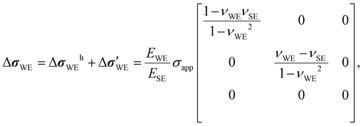
Unfortunately, the energy state of the reacting species in an electrode does depend on its mechanical state. For instance, the equilibrium potentials of Li–metal/SE and Na–metal/SE systems (both Li and Na have low yield strengths) are known to vary proportionally to external uniaxial stresses, applied perpendicular to the electrode/SE interfacial plane.19 In general, many electrode materials of interest (e.g., metal oxides and Si) have high elastic (Young's) moduli (e.g., >100 GPa), so a small strain (<1%) is sufficient to induce a stress in the several-hundred-MPa range. This is enough to change the equilibrium potential by several mV or more, which is large enough to measure and potentially influence battery behavior. In-plane biaxial stresses (i.e., when two orthogonal normal stresses are the only stresses present) also affect the equilibrium potential, demonstrated on thin-film silicon electrodes by Sethuraman et al.21 and Sheldon et al.22 Since any combination of stresses perpendicular and parallel to the electrode/SE interfacial plane can arise, incorporating the right coupling between electrochemistry and mechanics becomes critical when building SSB models, i.e., a full stress–strain tensor treatment is necessary. This is particularly so in situations where the volume changes in electrode active materials during (de)lithiation are anisotropic23–27 and the battery geometry is non-planar.28,29 In this paper, we achieve this goal by extending Goyal and Monroe's15 formalism to linear-elastic electrode materials. Although their analysis was restricted to SEs, their mechanical considerations are general enough to apply to electrode materials, especially when the electrode composition does not change. Based on their theory, we study three different loadings on an electrode/SE system, namely, (1) working electrode under out-of-plane uniaxial compression, (2) SE under in-plane uniaxial compression, and (3) SE under pure shear, to evaluate the full impact of the interfacial stress and strain tensors on the equilibrium potential. We make simplifying assumptions to arrive at approximate analytical solutions, whose accuracies are verified with numerical simulation. They are then compared with the expressions derived using the surface-normal stress as a stress descriptor, as Herring30 and Ganser et al.18 suggested. Note that we solely focus on electrodes at a fixed composition to highlight the mechanical influence on equilibrium potential; changes in electrode composition usually cause changes in the electrode stress state, and decoupling the mechanical impact from the compositional impact is not trivial. Our investigation shows that (1) mechanical properties of the WE and SE affect the equilibrium potential, (2) the deviatoric strain energy is negligibly small such that it is justifiable to ignore it, and (3) hydrostatic stress is a more general and widely applicable stress descriptor to use when writing mechanics-modified equilibrium potential, compared to the surface-normal stress.
2 General equilibrium-potential expression
Consider a working electrode (WE) deposited on a SE with a metal (reversible) reference electrode (RE) close by. The WE can be either a variable-composition electrode (e.g., lithium cobalt oxide) or a pure-composition electrode (e.g., lithium metal). When an electronic connection is made between the electrodes, metallic ions are shuttled between them via the SE, as a result of a redox reaction taking place at the electrode/SE interfaces. For an equilibrium-potential measurement, a galvanostat passes an infinitesimally small current through the system and the following reaction takes place at the WE/SE interface.| | | M(WE) ↔ Mn+(SE) + ne−(WE) | (1) |
Here, M denotes the metallic species participating in the redox reaction whose ionic form Mn+ is mobile in the SE, and n is the number of electrons involved. A bracketed subscript (either SE or WE) is added to each species to indicate its domain. At equilibrium, the relationship between the electrochemical potentials μi of the redox species i is μM = μ+ + μe−, where the subscripts M, +, and e− denote the metal atom, metal cation, and electron, respectively.
When an external stress is applied to the WE, its mechanical state changes, resulting in a change in μM. This change ΔμM should directly translate to a shift in the equilibrium potential ΔU because Δμ+ = 0 (ref. 18 and 19) and Δμe− = −nFΔU, where F is the Faraday constant. Therefore, decomposing ΔμM in terms of mechanical forces would reveal the dependency of ΔU on the changes in the WE's mechanical state. Mechanics-driven ΔμM can be written as ΔμM = ![[V with combining macron]](https://www.rsc.org/images/entities/i_char_0056_0304.gif) M(Δp − ε′:Δσ′) according to Goyal and Monroe,15
M(Δp − ε′:Δσ′) according to Goyal and Monroe,15![[thin space (1/6-em)]](https://www.rsc.org/images/entities/char_2009.gif) ‡ where M is the partial molar volume of the intercalated species M, p is the pressure, σ′ and ε′ are the deviatoric stress and strain tensors, respectively, and the double-dot operator : between the two tensors executes a dot product (i.e., generates a scalar by summing over all element-wise multiplication products; A:B = AijBij using the Einstein summation convention). As long as the full stress tensor σ is known, the deviatoric part (indicated by prime) can be obtained by subtracting the hydrostatic part (indicated by the superscript h) from it, i.e., σ = σh + σ′, where σh = tr(σ)I/3 = σiiI/3 with tr(σ) and I denoting the trace of σ and identity matrix, respectively. The same procedure applies to the strain-tensor decomposition. If all of the mechanical energy is transferred to the electrical energy (e.g., no phase changes, thus no voltage plateaus), the mechanics-driven ΔU can be expressed as
‡ where M is the partial molar volume of the intercalated species M, p is the pressure, σ′ and ε′ are the deviatoric stress and strain tensors, respectively, and the double-dot operator : between the two tensors executes a dot product (i.e., generates a scalar by summing over all element-wise multiplication products; A:B = AijBij using the Einstein summation convention). As long as the full stress tensor σ is known, the deviatoric part (indicated by prime) can be obtained by subtracting the hydrostatic part (indicated by the superscript h) from it, i.e., σ = σh + σ′, where σh = tr(σ)I/3 = σiiI/3 with tr(σ) and I denoting the trace of σ and identity matrix, respectively. The same procedure applies to the strain-tensor decomposition. If all of the mechanical energy is transferred to the electrical energy (e.g., no phase changes, thus no voltage plateaus), the mechanics-driven ΔU can be expressed as
| | 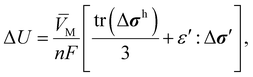 | (2) |
where the substitution Δ
p = −tr(Δ
σ)/3 = −tr(Δ
σh)/3 has been made.
Eqn (2) is general enough and therefore applies to any electrode materials in any configurations, as long as the electrode behaves linear-elastically and isotropically at a given composition and temperature. Although
M is a function of the WE's composition, this dependence can be safely dropped because of the fixed-composition assumption. Since
M is also a function of the WE's mechanical state,
eqn (2) should technically be written in an integral form. However, such dependence is difficult to quantify and often unknown; hence,
M is treated as a constant, in which case
eqn (2) suffices. Based on the first stress invariant and the derivation in Appendix A, it is clear that the square-bracketed term in
eqn (2) is coordinate-system independent, which makes Δ
U coordinate-system independent, as well. Given the choice of the coordinate system—often selected for theoretical convenience, thus arbitrary—should not affect the voltage measurement, this agrees with intuition. It is emphasized that only the
change in
σ contributes to Δ
U; thus, any residual stresses from fabrication should not affect measurements on samples on which stresses are applied.
It is noted that Goyal and Monroe's15 work is not the only expression elucidating the mechanical contribution to the Gibbs free energy. For example, Li et al.31 and later Larché and Cahn32—on which Sethuraman et al.21 and Sheldon et al.22 based their works—derived alternative expressions for the mechanics-modified μi with composition changes in mind. Their formulations explicitly include the (inverse of) elasticity tensor and therefore show clearly the composition dependence of the elastic properties like elastic modulus and Poisson's ratio. Bower et al.33 also arrived at a similar expression, which Bucci et al.34 employed in their model. Nonetheless, we base our analysis on Goyal and Monroe's work because we are only concerned with constant-composition scenarios in this paper; hence, Goyal and Monroe's expression is more straightforward to use. Unfortunately, the verification of each formalism and reconciliation between them is beyond the scope of this paper. This is a formidable task and therefore warrants a separate communication (note the works mentioned above were formulated with different applications in mind, leading to different assumptions and approximations). Practically, however, all these approaches should produce converging ΔU predictions for any systems in the linear-elastic regime, as the results and treatments of Sethuraman et al.21 and Baker et al.35 suggest. The same converging ΔU is reached in this study as well, by showing that the hydrostatic contribution accounts for the overwhelming majority (>99%) of the voltage response.
If needed, anisotropic mechanical responses can be captured by ε′ when the full elasticity tensor with anisotropic Poisson's ratios and elastic (Young's) moduli are introduced. For instance, a certain crystallographic orientation may be favored when an electrode is deposited on a monocrystalline SE substrate. Also, the lattice-structure changes in intercalation electrodes during (de)lithiation are not always isotropic.23–27 However, experimentally verified full elasticity tensors are rarely reported in the literature due to the difficulty of growing or isolating single-crystal structures. Furthermore, since many electrodes of practical interest (even thin films) are collections of many crystalline grains, only the macroscopic average behavior is of concern in practice. Therefore, we proceed by employing the isotropic and homogeneous elasticity tensor as in Appendix B (i.e., Poisson's ratio and elastic modulus are position- and direction-independent scalar quantities), which should be sufficient for this work and serve as a good first-order approximation.
With these in mind, we proceed to elucidate the mechanical effect on ΔU using eqn (2) in three different loading scenarios: (1) WE under out-of-plane uniaxial compression, (2) SE under in-plane uniaxial compression, and (3) SE under pure shear. Although the configuration typically examined and studied for battery applications is scenario I, a complex range of stress states is expected to arise in a compact particle electrode, including shear stresses, during battery operations. Hence, scenarios II and III can help provide fundamental insight on how different stress states can contribute to ΔU. Furthermore, the two scenarios are convenient for probing the research questions this paper aims to answer. Scenario II is most useful for determining whether the hydrostatic stress or surface normal stress is the right stress descriptor to use for ΔU. Scenario III most clearly illustrates the size of the deviatoric-strain-energy contribution to ΔU. Note that the two scenarios can in principle be produced in the lab with careful experimental designs; they are not only hypothetical. Our analytical study is based on a series of assumptions—in particular that the SE is significantly stiffer than the WE and the bonding between the two is strong—so as to avoid having to conduct the full contact-mechanics analysis. Although not completely general, these assumptions eliminate the need to consider any slippage or co-deformation at the interface, enabling tractable analytical derivations of the interfacial mechanical state. Numerical results are provided to verify the validity of the analytical assumptions, including when the SE and WE become comparably stiff, while retaining the strong-bonding assumption.
3 Mechanical analysis
3.1 Scenario I. Working electrode under out-of-plane uniaxial compression
We first study the most frequently encountered scenario when characterizing ΔU; a WE exposed to an out-of-plane uniaxial load, as in Fig. 1(a). Consider a WE deposited on a SE substrate for a platen-compression experiment, where the WE/SE sample is loaded uniaxially by a descending platen, in the direction perpendicular to the sample surface. This is a common experimental method for quantifying the stress-modified ΔU for WE/SE systems.19,36 Representative sample dimensions are around 1 mm for the WE and 30 mm for the SE (both in diameter), so the electrode takes up only a fraction of the SE surface. Ideally, the platen is flat and of the same size as the electrode, allowing the majority of the SE surface to remain unaffected by the applied force upon compression. We assume that the SE remains completely rigid and flat, and the bonding between the SE and WE is strong throughout the experiment. Numerical investigations will be undertaken in Section 4.1 to show that these are indeed reasonable assumptions even when both layers are elastic to a similar extent (i.e., their elastic moduli are of comparable magnitude).
 |
| | Fig. 1 Schematics of the three scenarios under study. The solid electrolyte (SE) is significantly stiffer than the working electrode (WE), i.e., EWE ≪ ESE, and the bonding between them is strong. The reference electrode (RE), also deposited on the SE, is a short distance away from the WE and mechanically relaxed. (a) Scenario I: WE under out-of-plane uniaxial compression. εs,ij denotes the j-direction strain on the surface whose normal is in the i direction in domain s = {WE, SE}. (b) Scenario II: SE under in-plane uniaxial compression. ΔσWE,iz denotes the z-direction stress acting on the surface whose normal points in the i direction in the WE. (c) Scenario III: SE under pure shear. | |
To build a stress tensor for the WE at the WE/SE interface, several factors need to be considered. Firstly, the platen exerts an externally applied stress σapp on the electrode in the z direction. At the same time, normal stresses σitf (itf for interface) in the x and y directions develop because the bonding between the two materials prevents the bottom surface of the electrode from moving at all. That is, σitf counteracts the Poisson effect on the xy plane to nullify the x- and y-direction normal strains. This is a reasonable boundary condition to impose because the electrochemical reaction taking place during the measurement (albeit at equilibrium) is an interfacial phenomenon, and the mechanical state away from the interface should be of no relevance. Using the mechanically fully relaxed state as the initial state, the change in the electrode stress tensor ΔσWE at the interface can be written as
| |  | (3) |
where
τij denotes the
j-direction shear stress on the surface whose normal is in the
i direction. Further assuming that the WE is a linear-elastic material with the elastic (Young's) modulus
EWE, shear modulus
GWE, and Poisson's ratio
νWE, the electrode strain tensor
εWE at the interface must be composed of the following elements, according to the stress–strain transformation outlined in Appendix B.
| |  | (4) |
The no-strain assumption at the interface (
i.e.,
εWE,ij = 0 for every permutation of
i = {
x,
y,
z} and
j = {
x,
y}) and symmetry in
εWE produce
τij = 0 and (1 −
νWE)
σitf =
νWEσapp; the latter can be rearranged and substituted back into
eqn (3) and (4) to eliminate
σitf. The hydrostatic and deviatoric parts can then be derived from the simplified tensors (see Appendix C), leading to the following Δ
U viaeqn (2).
| |  | (5) |
Evidently, ΔU is quadratic in σapp due to the deviatoric contribution and depends on νWE and EWE, which were not recognized in previous works dealing with similar systems.18,19 The quadratic dependence is natural because the strain energy is proportional to the stress squared in the linear-elastic regime. The size of the deviatoric contribution relative to the hydrostatic contribution is simply given by the ratio of the second and first terms inside the square brackets in eqn (5), i.e.,  . Since the quotient containing νWE is on the order of 1 and σapp/EWE < 10–3 typically, the deviatoric part should be approximately 0.1% of the hydrostatic part or less. Interestingly, eqn (5) produces ΔU = Mσapp/nF when the WE is incompressible (i.e., νWE = 0.5), which is what Carmona et al.19 observed for Li/LLZO system. For lithium, this incompressible-fluid assumption is reasonable because it has a relatively low yield strength (0.73 MPa (ref. 37)) and is known to creep under the typical battery-operating conditions.12,13,38,39 The fact that the elastic modulus of lithium metal (7.82 GPa (ref. 37)) is much lower than those of typical SEs (see Table 1) further warrants the use of eqn (5). The same applies to sodium, which is more susceptible to creep than lithium and whose elastic modulus is lower than that of lithium.40 Other common electrode materials do not obey complete incompressibility, since νWE < 0.5 usually. As the WE becomes more and more compressible, the Poisson effect should become less and less pronounced, reducing the x- and y-direction normal stresses arising from the rigid interfacial bonding. In the limit νWE → 0 where the WE exhibits no lateral deformation, the influence of the x- and y-direction normal stresses on ΔU disappears. Instead, it is entirely controlled by σapp in the z-direction, which makes sense.
Table 1 Electrode and electrolyte properties
| Material |
E (GPa) |
ν
|
G (GPa) |
Li (cm3 mol−1) |
Notes and references |
| LCO |
191 |
0.24 |
80 |
8.5 (α = 0.5) |
LiαCoO2 |
| −3.5 (α = 0.8) |
Koerver et al.,9 Cheng et al.51 |
| NMC-111 |
199 |
0.25 |
78 |
8 (α = 0.25) |
LiαNi0.33Mn0.33Co0.33O2 |
| 0.7 (α = 0.5) |
Koerver et al.,9 Cheng et al.52 |
| 1.5 (α = 0.8) |
| LiPON |
79 |
0.27 |
— |
— |
Li5.5PO4.5N0.6 |
| Xu et al.53 |
| LLZO |
149.8 |
0.257 |
— |
— |
Li6.24La3Zr2Al0.24O11.98 |
| Ni et al.54 |
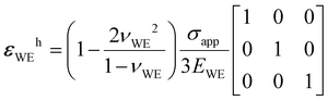
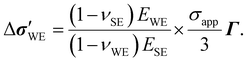
3.2 Scenario II. Solid electrolyte under in-plane uniaxial compression
As Sethuraman et al.21 demonstrated, an electrode in plane stress (where the non-zero stress components act within a single plane only) undergoes an equilibrium-potential shift relative to a mechanically relaxed state. In this section, we focus on the effects of a planar normal stress on ΔU, where an external stress σapp is applied on the two parallel sides of the SE, as Fig. 1(b) shows. This setup is chosen because the direct application of plane stresses on the WE is expected to be difficult experimentally, due to its size and thickness in typical mechanics-induced ΔU characterization experiments.
Now, consider a SE made up of a main section and a subsidiary section, as illustrated in Fig. 1(b). Although a distinction between the two sections is made to aid the description, it is reminded that we are working with one continuous piece of SE. The WE sits on the main section that directly experiences a normal stress σapp in the x direction. The subsidiary section accommodates the RE and is mechanically relaxed. We assume that the SE is much stiffer than the WE (i.e., EWE ≪ ESE), and the surface area the WE occupies on the SE is small, so the deposited electrode has minimal influence on the SE's mechanical response to the applied stresses. Further ignoring the mechanical impact of the subsidiary section on the main section, the stress the main section experiences relative to the stress-free state ΔσSE can be written as
| |  | (6) |
The corresponding strain in the SE—assuming it is linear elastic—can be easily calculated based on the Poisson effect using the transformation in Appendix B. If the bonding at the WE/SE interface is strong such that the SE displacements (uSE,ij) on the xy plane directly translate to the displacements in the WE (uWE,ij), then one can set uWE,ij = uSE,ij × LWE/LSE for i = {x, y, z} and j = {x, y}, where LWE and LSE denote the length of the WE and SE in the j direction, respectively. Assuming strains are small, the displacements can be written as us,ij = εs,ijLs for s = {WE, SE}; thus, εWE,ij = εSE,ij ensues for i = {x, y, z} and j = {x, y}. The off-diagonal terms are determined based on the symmetry relation, i.e., εWE,iz = εWE,zi for i = {x, y}. In contrast, the z-direction normal strain εWE,zz is not constrained, so we proceed without specifying its value. Thus, the strain tensor for the WE at the interface εWE is
| | 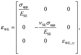 | (7) |
where
ESE and
νSE are the elastic (Young's) modulus and Poisson's ratio of the SE. When a large volume change is induced as the composition of the WE changes (
e.g., silicon undergoing lithiation and delithiation), it is important to consider the interfacial shear effects.
41,42 In this scenario, however, the main source of the interfacial shear stress and strain is the strong interfacial bonding, not a composition change. Thus, most of the interface should remain shear-free, as Mao
et al.43 illustrated using a shear-lag model, and this justifies the null off-diagonal entries in
eqn (7). Using the inverse of the transformation matrix in Appendix B, the stress tensor for the WE at the interface Δ
σWE can be obtained. The unknown strain in Δ
σWE can be identified by employing the plane-stress assumption,
i.e., set Δ
σWE,zz = 0 as off-diagonal Δ
σWE,iz and Δ
σWE,zi are zero already. This is reasonable because the WE is not exposed to any external stresses in the
z direction, nor is it constrained in this direction. This condition is achieved when
εWE,zz is
| | 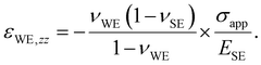 | (8) |
Substituting this produces the following Δ
σWE components
| |  | (9) |
with all other components being zero. The full stress and strain tensors, as well as their hydrostatic and deviatoric parts, are outlined in Appendix D. Incorporating these into
eqn (2), Δ
U becomes
| |  | (10) |
As before, the quadratic term stems from the deviatoric strain energy. The ratio of the second and first terms inside the square brackets in
eqn (10) shows the relative importance of the deviatoric contribution. Dropping second-order and higher terms involving
νWE and
νSE, the ratio can be approximated as

, where the quotient involving
ν's is on the order of 1. Given
σapp/
ESE < 10
–3 typically, the deviatoric part again reduces only to approximately 0.1% of the hydrostatic part or less. It is emphasized that this equation is only accurate when the SE strains remain unaffected by the presence of the WE. This is an idealized assumption and incongruence would be present in reality, especially when the WE is relatively stiff compared to the SE (the interfacial bonding might be compromised in this case, as well). Thus, the accuracy of
eqn (10) is expected to decrease as
EWE increases, which is demonstrated numerically in Section 4.2.
A practical setup that can emulate the plane-stress condition in Fig. 1(b) may be contrived by modifying the standard cantilever system, as illustrated in Fig. 2. One end of the cantilever is completely fixed to a wall or a rigid frame, while a weight can be hung at the other end to generate a combination of normal and shear stresses across the beam. For cantilevers made of homogeneous, linear-elastic materials with large enough cross-sectional height-to-width ratio (h/b), the stress distributions and deflection (displacement from the unloaded position) can be easily obtained from the standard mechanical-engineering textbooks.44,45 A direct application of such analytical expressions may be reasonable if the cantilever beam in Fig. 2 was made entirely of a SE and the WE that sits on its surface is small enough and has a lower elastic modulus than the SE. However, utilizing such analytical expressions are likely inaccurate for practical setups because many WEs are stiffer than typical SEs, as Table 1 shows. Furthermore, the commonly used SEs would be too brittle to sustain any significant hanging weight in this configuration; even attaching them to the supporting wall or frame would be challenging. This issue may be circumvented by embedding a small piece of SE into a cantilever beam made of a more pliable material like acrylic (whose elastic modulus is 2.2 GPa (ref. 46)). As Fig. 2(b) shows, a notch can be carved out of the beam to accommodate the SE, with the bonding between the two provided by an appropriate adhesive. To avoid delamination, the SE should only experience compression; this is ensured by placing it in the bottom half of the beam. Although the RE should be positioned where the SE is mechanically fully relaxed, e.g., at the end of the beam (x = L), this is impractical. Instead, placing it on or close to the center line of the beam (y = 0) should be a good alternative because the normal stress (and therefore any contribution to ΔU) should be small there. Note that a non-zero shear stress is expected to be present along the center line, but its influence on ΔU is small enough to ignore, as will be illustrated in Section 3.3. The last hurdle in using eqn (10) is that σapp acting on the SE is difficult to obtain analytically in this cantilever setup. One possible way of acquiring it is to attach a strain gauge to the back of the cantilever beam to infer it, assuming linear elasticity holds.
 |
| | Fig. 2 Illustration of the cantilever experiment to emulate scenario II to provide experimental validation of eqn (10). (a) Front view. (b) Side view. | |
3.3 Scenario III. Solid electrolyte under pure shear
A close examination of eqn (2) shows that a non-zero ΔU must arise even if the electrode experiences no changes in its hydrostatic-stress state; shear stresses and strains generate deviatoric strain energy that affects its electrochemical potential. An obvious way to test the shear effect is to conduct a torsion experiment, i.e., twist a WE/SE system mounted on a cylinder surface and measure the equilibrium potential. Unfortunately, this is cumbersome to carry out experimentally because (1) it may be more laborious to deposit WE/SE systems on a curved surface than on a flat surface, and (2) it would be difficult to position a RE at a mechanically relaxed location. The second point arises because the torsion-induced shear stress is directly proportional to the radial position in the cylinder,44 so the RE has to be at the center of the cylinder—not on the surface—to be completely free from stresses, which complicates sample preparation significantly. To circumvent these issues, one may exploit the fact that the description of a given mechanical state is coordinate-system dependent and thus not unique. From Mohr's circle for plane stress, it is easy to see that a system solely subjected to two orthogonal normal stresses of equal magnitude but opposite directions (see Fig. 1(c)) is equivalent to the one experiencing pure shear stress, once the coordinate system is rotated by 45°. Because the deviatoric strain energy in eqn (2) is coordinate-system independent (as shown in Appendix A), the shear effect on ΔU can be assessed while only applying normal stresses in the coordinate system the experiment is conducted in.
As in scenario II, consider a WE and a RE deposited on the main and subsidiary sections of a SE, respectively, as shown in Fig. 1(c). The main section of the SE experiences compression in the x direction and tension in the y direction. Both external stresses have the same magnitude |σapp| to emulate pure shear. Assuming again that the subsidiary section has no influence on the mechanical state of the main section and EWE ≪ ESE, the stress tensor for the SE relative to the stress-free state ΔσSE can be written as
| |  | (11) |
The corresponding strains in the SE can be calculated
via the stress–strain transformation in Appendix B. If the interfacial bonding in the
xy plane is perfect and strong such that the
x- and
y-direction displacements in the SE put the WE under the same displacements, then
εWE,ij =
εWE,ij for
i = {
x,
y,
z} and
j = {
x,
y}, which are the same boundary conditions as the ones in scenario II. Imposing symmetry, the strain tensor for the WE at the interface
εWE reduces to
| |  | (12) |
where
ESE and
νSE are the elastic (Young's) modulus and Poisson's ratio of the SE. As in scenario II, the interfacial shear effects are ignored based on Mao
et al.'s
43 results. The remaining
z-direction normal strain
εWE,zz can be identified when the plane-stress assumption (
i.e., Δ
σWE,iz = Δ
σWE,zi = 0) is made. This is reasonable because the SE is not subjected to any mechanical constraints in the
z direction, and all external stresses act only in the
x and
y directions. Coincidentally, this is achieved when the system is in a plane-strain state (
i.e.,
εWE,iz =
εWE,zi = 0), so Δ
σWE reduces to
| |  | (13) |
It is easy to see that the WE/SE interface is under pure shear by subjecting the above tensor to a 45° rotation in the xy plane, as expected. Because ΔσWE is traceless and its off-diagonal terms are zero, ΔσWEh = 0 and  . Similarly, εWEh = 0 and
  with εWE,zz = 0. Incorporating these into eqn (2), ΔU becomes
| |  | (14) |
Thus, shear stress induces a purely quadratic response in Δ
U but its effect is expected to be small unless
EWEσapp/
ESE2 > 1. Again, this equation is only truly valid when the deposited WE does not influence the SE strains, which is difficult to argue when the WE and SE are comparably stiff. Therefore, the actual Δ
U is expected to deviate from
eqn (14) as
EWE increases; see Section 4.3 for numerical demonstration.
3.4 Numerical analysis
The validity of ΔU in eqn (5), (10), and (14) is directly tied to the soundness of the various assumptions employed in deriving them. Unfortunately, many WEs are comparably stiff to commonly used SEs, and thus the critical EWE ≪ ESE assumption is violated in many practical experimental systems. In such cases, obtaining the exact analytical solutions is challenging; instead, utilizing numerical simulation tools becomes a more favorable proposition. Through COMSOL-Multiphysics simulations, discrepancies between the simplified and more realistic mechanical states are calculated and incorporated into the ΔU equations by employing a correction factor f in the next section.
We simulate a WE/LLZO system whose interface is perfectly bonded under the three loading scenarios. The WE has the width, depth, and height of 200, 200, and 50 μm, respectively, and the SE is a cube of 1000 μm in edge length. A natural protocol for discretization is to partition the system volume based on the distance between the location to be discretized and the WE/LLZO interface. Hence, a variable meshing density that is higher for locations closer to the edges where the SE and WE meet (not the interfacial plane) is used to achieve numerical efficiency and reliability. To ensure convergence, the edge meshing density n (from which COMSOL builds the meshing in the rest of the system) is gradually increased until stable results are obtained. The simulation results presented in the next section use n that produces consistent results with those generated with at least 1.75n. Another point to note is that COMSOL does not evaluate the WE's stress state exactly at the interface. This is because a stress tensor is only defined within each domain, not at the geometric interface itself (instead, an interfacial force balance is carried out at the domain boundaries, which means a surface-normal vector suffices to describe the mechanical state there). Therefore, an evaluation plane is placed within the WE domain just above the interface (displacement by 0.05% of the WE height) to obtain the interfacial mechanical states. Given the proximity to the interface, they should be very close to the actual interfacial values. For reference, a representative stress distribution for each scenario is provided in Fig. S1 of ESI.† It is evident that the distributions are not uniform across the interface, especially in the regions close to the edges where the WE and SE meet. Our analytical treatment is based on the assumption that a position-independent single mechanical state arises in response to an applied stress. Therefore, the COMSOL results reveal the inherent limitations of our analytical approach. The presence of stress distribution further complicates the interpretation of the results because it implies a distribution of electric potential exists, i.e., mixed-potential theory is necessary to accurately delineate the voltage response. Such an analysis is beyond the scope of this paper, and we leave this for future work. Instead, the average mechanical state across the evaluation plane is taken as the characteristic state that determines ΔU. Provided the electrode material has sufficient electronic conductivity, the electrode will be equipotential, and this is a reasonable approximation. Hence, all our discussions in the next section evolve around the average ΔσWE and εWE. Correction factors f are also anchored to the average state.
4 Results and discussion
ΔU expressions derived in the previous section are now evaluated quantitatively, based on the common cathode and electrolyte material properties, as tabulated in Table 1. Numerical simulation results are presented alongside for validation. Note LLZO has been used as the SE for all COMSOL simulations. The ΔU equations can also be applied to anode materials, but we omit such application here because it is straightforward enough to do. One thing to bear in mind in this case is that the elastic properties of common anode materials such as silicon and graphite are more sensitive to the insertion-species (e.g., lithium) content than what typical oxide-based cathodes exhibit.47–50 Hence, working with a consistent set of elastic properties, appropriate for the given composition, would be important.
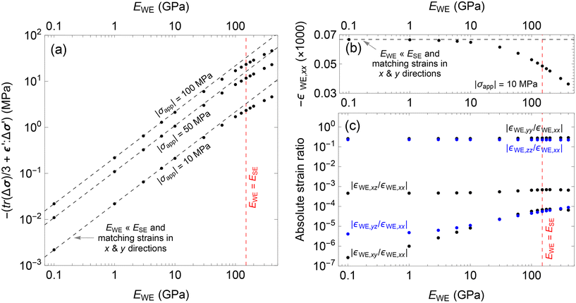
4.1 Scenario I. Working electrode under out-of-plane uniaxial compression
Fig. 3(a) shows the simulated WE mechanical state relevant to ΔU, i.e.,  as outlined in eqn (2), averaged across the evaluation plane just above the WE/SE interface. The horizontal dashed lines show the analytical values that obey the no-strain assumption in eqn (5). Evidently, the difference between the two is small when EWE ≈ 7 GPa (EWE/ESE ≈ 0.05) but increases at both smaller and larger values of EWE. When EWE < 3 GPa (EWE/ESE < 0.02), eqn (5) is not relevant because the small-strain assumption does not hold for the σapp values modeled. When the SE and WE become comparably stiff, the validity of the no-strain assumption diminishes quickly, as evident in Fig. 3(c); while the analytical expression for the main strain component εWE in eqn (21) works well across the EWE range evaluated (see Fig. 3(b)) and the simulated shear strains remain small (less than 0.1% of εWE,zz), the normal strains increase noticeably. As a result, the error in
  grows to 11% of the analytical value when EWE/ESE = 0.67 and 15% when EWE/ESE = 2 for all three σapp values. Although not constant, the error range is narrow, so a correction factor of f = 1.13 may be introduced to eqn (5) for WE/SE systems whose elastic-modulus ratio lies in the range 0.67 ≤ EWE/ESE ≤ 2.7. This correction should apply well to the systems made up of the materials listed in Table 1, where the combination that generates the largest elastic-modulus ratio is NMC-111/LiPON with EWE/ESE = 2.6. The use of constant f is further corroborated by the fact that the difference in Poisson's ratio between LCO and NMC-111 (0.24 and 0.25, respectively) is small, and so is the difference between LLZO and LiPON (0.257 and 0.27, respectively).
 |
| | Fig. 3 Scenario-I COMSOL results for a working electrode (WE) deposited on the LLZO solid electrolyte (SE). The simulation results, averaged across an evaluation plane, are shown with circular markers. Averages are taken across the evaluation plane whose z coordinate is 0.05% of the WE height above the WE/SE interface. The WE has Poisson's ratio of νWE = 0.24, and LLZO has the elastic modulus of ESE = 149.8 GPa. Note that compression produces negative stress and strain. (a) The average WE mechanical state that contributes to ΔU is plotted against the WE elastic modulus (EWE) for three out-of-plane uniaxial loadings σapp. The horizontal dashed lines correspond to the zero-interfacial-strain assumption in eqn (5). (b) The average z-direction normal strain in the WE (εWE,zz) is plotted against EWE for |σapp| = 10 MPa. The dashed line represents the analytical strain in eqn (21). (c) The magnitude of the average WE strains relative to εWE,zz are plotted against EWE. The plotted data is for |σapp| = 10 MPa, but the results for |σapp| = 50 and 100 MPa are essentially identical to what is presented in panel (c). | |
ΔU for LiαCoO2 (LCO) and LiαNi0.33Mn0.33Co0.33O2 (NMC-111) under an out-of-plane uniaxial load σapp is plotted in Fig. 4 using f = 1.13 and eqn (5) (note that the equation is independent of the SE properties). α designates the amount of lithium in a cathode unit cell. Evidently, the linear term dominates despite the presence of the quadratic term. Given the maximum |σapp| imposed during the typical platen-compression experiment is below 1 GPa, and common cathode materials have EWE > 100 GPa,55 the square-bracketed quantity in eqn (5) reduces essentially to 1. The quadratic behavior would become more obvious when σapp is comparable to EWE in magnitude, but then eqn (5) would lose its validity; the material would yield. Using hardness H as a proxy for the yield strength σY (since H ≈ 3σY with H < 20 GPa for common cathode materials55), applied stresses larger than 7 GPa would very likely cause deviation from eqn (5). Thus, for the conventional platen-compression experiment conducted at a fixed electrode composition, dropping the square-bracketed quantity should only incur a marginal error. This simplification is also appropriate for battery modeling because stresses beyond 7 GPa is unlikely in SSBs (the largest change in stress state Sethuraman et al.21 observed during charging a thin-film silicon electrode was about 1.6 GPa). Indeed, the mechanics-induced ΔU is small compared to the composition-driven ΔU (operational voltage window for both LCO and NMC-111 is 2.7–4.3 V (ref. 56 and 57)), but it can still play a significant role in determining the interfacial-current-density distribution. For example, Jung et al.58 numerically demonstrated that the mechanics-induced ΔU completely changed the current-density profile at the Li-metal/LLZO interface, compared to the one that omitted mechanical effects (the Butler–Volmer equation was used in their study, and the maximum magnitude of mechanics-modified ΔU was 7.7 mV arising from 58 MPa pressure at the Li–metal asperity tip).
 |
| | Fig. 4 Scenario-I equilibrium potential ΔU plotted using eqn (5) as a function of the out-of-plane uniaxial applied stress σapp on various working electrodes. Note that a compressive stress takes a negative sign and a correction factor of f = 1.13 has been used. The black and blue lines represent ΔU for LCO and NMC-111, respectively. Different compositions α are plotted for each electrode material, indicated by different line types. The red line shows ΔU when the surface-normal stress  is used, where is used, where  is the surface-normal vector. is the surface-normal vector. | |
When the surface-normal stress  (
( is the surface-normal vector) is used as the stress descriptor, as Herring30 and Ganser et al.18 suggested, ΔU in red in Fig. 4 ensues for LCO at α = 0.5. Clearly, the voltage response is exaggerated compared to the solid black line calculated from eqn (5); σn produces ∂ΔU/∂σapp 63% larger than the one based on the full stress–strain tensor treatment even after incorporating the correction f = 1.13. Again, the implications of this difference may be significant when calculating the interfacial-current-density distribution.
4.2 Scenario II. Solid electrolyte under in-plane uniaxial compression
The simulated mechanical state  that affects ΔU is shown in Fig. 5(a), as well as what the analytical expression in eqn (10) predicts as dashed lines. To recapitulate, eqn (10) was derived for a perfectly strain-matched interface with EWE ≪ ESE, such that the SE strains stay independent of the presence of the deposited WE. Because the external stress on the WE is administered via the SE, the stress magnitude the WE experiences is significantly reduced compared to |σapp|. Hence, the linear-elasticity assumption holds over a wider EWE window than in scenario I. Clearly, the agreement between the analytical expression and numerical solutions is good, as long as EWE < 30 GPa (EWE/ESE = 0.2). However, the discrepancy between the two grows as the WE becomes stiffer;
  is reduced by 22% relative to eqn (10) when EWE/ESE = 0.67 (EWE = 100 GPa) but as much as 47% when EWE/ESE = 2.7 (EWE = 400 GPa) for all three σapp values. Therefore, a correction factor 0.53 ≤ f ≤ 0.78 is necessary when using eqn (10) for practical experimental systems.
 |
| | Fig. 5 Scenario-II COMSOL results for a working electrode (WE) deposited on the LLZO solid electrolyte (SE). The simulation results, averaged across an evaluation plane, are shown with circular markers. Averages are taken across the evaluation plane whose z coordinate is 0.05% of the WE height above the WE/SE interface. The WE has Poisson's ratio of νWE = 0.24, and LLZO has the elastic modulus of ESE = 149.8 GPa. Note that compression produces negative stress and strain. (a) The average WE mechanical state that contributes to ΔU is plotted against the WE elastic modulus (EWE) for three in-plane uniaxial loadings σapp exerted on the SE. The dashed lines correspond to what eqn (10) predicts, where the deposited WE has no effect on the SE strains due to the EWE ≪ ESE assumption, along with the perfectly matched interfacial strains across the two domains. (b) The average x-direction normal strain in the WE (εWE,xx) is plotted against EWE for |σapp| = 10 MPa. The horizontal dashed line represents the analytical strain in eqn (7). (c) The magnitude of the average WE strains relative to εWE,xx are plotted against EWE. The plotted data is for |σapp| = 10 MPa, but the results for |σapp| = 50 and 100 MPa are essentially identical to what is presented in panel (c). | |
To identify the cause of deviation between the analytical and numerical results, the simulated WE strains are plotted in Fig. 5(b) and (c). Note that delamination is not the source of this discrepancy because the strains in the WE and SE can be matched as boundary conditions in COMSOL. Instead, the main culprit is the x-direction normal strain εWE,xx in Fig. 5(b); it is affected by how stiff the WE is and steadily diminishes as EWE increases beyond EWE = 30 GPa. This is in line with the expected behavior; a soft deposit will conform to the substrate deformation, while a stiff deposit will resist it, reducing the extent of deformation. Nonetheless, the relative magnitude of the strain components in eqn (24) are preserved, as Fig. 5(c) demonstrates.
Unlike in scenario I, a constant f cannot be selected because the variability in 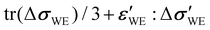 grows noticeably with increasing EWE. Nonetheless, f = 0.66 (this corresponds to the numerical result at EWE = 200 GPa in Fig. 5(a)) is appropriate for LCO and NMC-111 deposited on LLZO, which is incorporated into eqn (10) to plot ΔU in Fig. 6(a). The quadratic behavior in ΔU is clearly insignificant and the square bracket in eqn (10) can be safely discarded. The same is observed when LLZO is replaced with LiPON, as Fig. 6(b) illustrates. Note that LiPON is less stiff than LLZO (i.e., ELiPON < ELLZO) and therefore elevates ΔU because of the factor EWE/ESE present in eqn (10). However, the full effect of EWE/ESE is dampened because the deviation from the EWE ≪ ESE assumption is larger for LiPON (f = 0.53) than for LLZO (the correction factor f = 0.53 for LiPON is based on the EWE = 400 GPa result in Fig. 5(a), which has EWE/ESE = 2.7. The same ratio for NMC-111/LiPON is 2.5, which is close enough.).
 |
| | Fig. 6 Scenario-II equilibrium potential ΔU of various working electrodes plotted using eqn (10), as a function of in-plane applied stress σapp on (a) LLZO (correction factor f = 0.66) and (b) LiPON (correction factor f = 0.53). Note that compression produces negative stress. The black and blue lines represent ΔU for LCO and NMC-111, respectively. Different compositions α are plotted for each electrode material, indicated by different line types. The red line shows ΔU when the surface-normal stress  is used, where is used, where  is the surface-normal vector. is the surface-normal vector. | |
Fig. 6 shows that the mechanics-induced ΔU should be measurable, as long as Li is large enough (ΔU for NMC-111 α = 0.5 and 0.8 may be difficult to separate from the experimental noise). This is contrary to the predicted nil response from using the surface-normal stress σn. Therefore, measuring ΔU using an electrode deposited on a SE that experiences in-plane compression—as in Fig. 1(b) and 2—is a useful setup that can (in)validate Goyal and Monroe's15 theory. Nevertheless, there already exists an experimental result that refutes the use of σn; Sethuraman et al.21 measured non-zero ΔU stemming from in-plane biaxial stresses, where σn = 0. In this regard, using hydrostatic stress is more general and widely applicable than σn.
4.3 Scenario III. Solid electrolyte under pure shear
The relevant mechanical state to ΔU, i.e.,  , is plotted in Fig. 7(a); circular markers indicate numerical results while dashed lines correspond to the analytical expression in eqn (14). Contrary to the expectation, the |σapp| = 10 MPa simulation results are about 40% higher than the analytical expression in the lower EWE range. This is because the simulated hydrostatic stress tr(ΔσWE)/3 does not exactly amount to zero; normal stresses σWE,xx and σWE,yy do not nullify each other completely when added, and the plane-stress condition (ΔσWE,iz = ΔσWE,zi = 0; the i = z case is of specific concern here) is not exactly met. In particular, the COMSOL-generated tr(ΔσWE)/3 for |σapp| = 10 MPa is comparable in size to
  , hence the deviation in Fig. 7(a) is noticeable. In contrast,
  is more dominant for |σapp| = 50 and 100 MPa, and the numerical and analytical results align well, at least up to EWE = 30 GPa. Beyond this point, the difference between the two grows steadily as EWE approaches and surpasses ESE. This trend is also reflected in the x-direction normal strain εWE,xx in Fig. 7(b). Nevertheless, the strains retain the relative sizes eqn (12) prescribes, as Fig. 7(c) shows.
 |
| | Fig. 7 Scenario-III COMSOL results for a working electrode (WE) deposited on the LLZO solid electrolyte (SE). The simulation results, averaged across an evaluation plane, are shown with circular markers. Averages are taken across the evaluation plane whose z coordinate is 0.05% of the WE height above the WE/SE interface. The WE has Poisson's ratio of νWE = 0.24, and LLZO has the elastic modulus of ESE = 149.8 GPa. Note that compression produces negative stress and strain. (a) The average WE mechanical state that contributes to ΔU is plotted against the WE elastic modulus (EWE) for three shear loadings σapp exerted on the SE. The dashed lines correspond to what eqn (14) predicts, where the deposited WE has no effect on the SE strains due to the EWE ≪ ESE assumption, along with the perfectly matched interfacial strains across the two domains. (b) The average x-direction normal strain in the WE (εWE,xx) is plotted against EWE for |σapp| = 10 MPa. The horizontal dashed line represents the analytical strain in eqn (12). (c) The magnitude of the average WE strains relative to εWE,xx are plotted against EWE. The plotted data is for |σapp| = 10 MPa, but the results for |σapp| = 50 and 100 MPa are essentially identical to what is presented in panel (c). | |
It is clear that a correction factor f that depends on EWE/ESE and σapp is necessary for scenario III unlike in the previous cases; the incongruence between the numerical and analytical results does not lie within a narrow band as in scenario I, nor is it σapp independent as in scenario II. Rather than deploying a functional form of f, we proceed with eqn (14) as is, i.e., we use f = 1, to evaluate the ΔU characteristics. For practical systems where EWE > ESE, this is a good approximation at least for the lower σapp range around 10 MPa, as Fig. 7(a) illustrates. For higher σapp, this choice generates the maximum expected voltage response. Fig. 8(a) shows ΔU calculated from eqn (14) for LCO and NMC-111 deposited on LLZO. Obviously, ΔU is not completely nullified in the absence of normal stresses, an aspect that employing the surface-normal stress overlooks. However, the voltage responses to pure shear are about two orders of magnitude smaller than the responses to uniaxial loadings in Fig. 4 and 6. This is not surprising, given EWEσapp/ESE2 ≪ 1 for all systems considered in Fig. 8. In fact, the shear effect—or more generally deviatoric effect—is bound to be minute relative to the hydrostatic contribution by design. Even if the components of Δσ′ have the same order of magnitude as Δp = −tr(Δσh)/3, multiplying them with ε′ substantially decreases their shares in ΔU, provided strains would have to remain below 5% in general for the linear-elasticity assumption to hold. As a result, it is likely difficult to verify the deviatoric influence on ΔU experimentally, as the resulting voltage responses would be inundated with noise (at least if setups similar to the one Carmona et al.19 used were employed). For practical purposes, it would be safe to ignore the deviatoric contributions in constructing ΔU. Finally, Fig. 8(b) shows the responses LCO and NMC-111 produce when deposited on LiPON. Since ΔU is inversely proportional to ESE2 and ELLZO/ELiPON = 1.9, the voltage responses from WE/LiPON is about 3.6 larger than that from WE/LLZO.
 |
| | Fig. 8 Scenario-III equilibrium potential ΔU of various working electrodes plotted using eqn (14) without any correction (f = 1), as a function of the applied stress σapp on (a) LLZO and (b) LiPON. The SEs experience a compressive stress in x direction and a tensile stress of the same magnitude in the y direction, i.e., they are under pure shear. The black and blue lines represent ΔU for LCO and NMC-111, respectively. Different electrode compositions α are plotted for each electrode material, indicated by different line types. The red line shows ΔU when the surface-normal stress  is used, where is used, where  is the surface-normal vector. is the surface-normal vector. | |
5 Conclusions
Mechanics-modified equilibrium potentials for linear-elastic electrode materials were derived using the full stress–strain tensor treatment of Goyal and Monroe15 and shown to have mechanical-property dependence, provided all mechanical energy transforms to electrical energy. The analytical expressions for the three experimental scenarios considered, as summarized in Table 2, revealed that the deviatoric effect can be safely ignored for battery-modeling purposes. Instead, hydrostatic stress—with appropriate boundary conditions—is a sufficiently accurate approximation, suitable in conditions relevant to SSBs. This conclusion arises because the deviatoric mechanical energy is bound to be small compared to the hydrostatic mechanical energy. Numerical results were also provided to demonstrate the validity of the analytical expressions. Based on these results, correction factors were introduced to supplement the use of the analytical expressions in more practical systems. Furthermore, we conclude that hydrostatic stress—not surface-normal stress—is a more general and widely applicable stress descriptor in equilibrium-potential expressions, especially when in-plane normal stresses exist across the interfacial plane. Nonetheless, experimental verification of the derived expressions would be necessary to more confidently incorporate them in SSB models; the cantilever-beam setup outlined in Section 3.2 is a prime candidate for such validation.
Table 2 Summary of the mechanics-modified equilibrium potential ΔU using the big-O notation. Note that only the WE/SE interfacial mechanical state affects ΔU. Each scenario corresponds to an experimental setup that generates a unique stress state at the interface
| Scenario |
Mechanics-modified ΔU (V) |
| I. WE under out-of-plane uniaxial compression |

|
| • Incompressible fluid (νWE = 0.5) |

|
| II. SE under in-plane uniaxial compression |

|
| III. SE under pure shear |
ΔU = O(σapp2) |
Author contributions
Conceptualization: T.J., Y.S., and P.A. Investigation and formal analysis: T.J. Validation: T.J. and Y.S. Writing – original draft: T.J. Writing – review and editing: T.J., Y.S., G.M.V., and P.A. Visualization: T.J. Supervision: G.M.V. and P.A. Project administration and resources and funding acquisition: P.A.
Data availability
The COMSOL models used in this paper can be found in the Digital Repository at the University of Maryland (DRUM) at https://hdl.handle.net/1903/33809 with https://doi.org/10.13016/riru-jrdr.
Conflicts of interest
The authors declare that they have no known competing financial interests or personal relationships that could have appeared to influence the work reported in this paper.
Appendix A. Coordinate-system invariance of deviatoric strain energy
Given a coordinate transformation matrix Q that transforms a tensor α from one coordinate system to another viaαt = Q·α·QT (where the subscript t and superscript T denote transform and transpose, respectively), the invariance of the deviatoric strain energy can be derived easily using the Einstein notation. The traceless deviatoric component of αt can be written as| |  | (15) |
where δij is a Kronecker delta, and the relation QkpQkq = δpq has been used to obtain the second line in eqn (15). Substituting the stress Δσ′ and strain ε' tensors in place of α and performing the double-dot product, the desired result is produced.| |  | (16) |
In writing the Einstein notation for the change in stress, the delta symbol (Δ) was omitted for notational compactness. Note that in the fourth line of eqn (16), δpqσpq and δijδij can be replaced by δmnσmn and δmnδmn, respectively, because p, q, i, and j are dummy indicies.
Appendix B. The Poisson effect
When the material under study is linear elastic, and when the Poisson effect prevails isotropically, then the stress (σij) and strain (εij) components are connected via| | 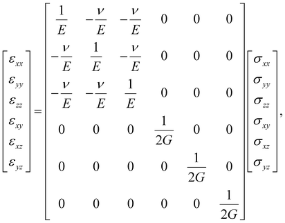 | (17) |
where ν, E, and G are Poisson's ratio, elastic (Young's) and shear moduli of the material, respectively.
Appendix C. Scenario I. Working electrode under out-of-plane uniaxial compression
Applying the x- and y-direction zero-strain conditions at the WE/SE interface, as discussed in Section 3.1, the change in the electrode stress state ΔσWE in eqn (3) reduces to| | 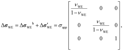 | (18) |
where σapp is the applied stress in the z direction. This tensor can be divided into a hydrostatic part ΔσWEh and a traceless deviatoric part  , as below.
| |  | (19) |
| |  | (20) |
The strain tensor εWE in eqn (4) becomes
| |  | (21) |
with the following hydrostatic
εWEh and deviatoric

parts.
| |  | (22) |
| |  | (23) |
Appendix D. Scenario II. Solid electrolyte under in-plane uniaxial compression
Following the x- and y-direction matching-strain treatment at the WE/SE interface, as outlined in Section 3.2, the strain tensor εWE in eqn (7) reduces to| |  | (24) |
after substituting eqn (8). Naturally, the hydrostatic εWEh and deviatoric  parts become
| |  | (25) |
| |  | (26) |
where| |  | (27) |
The change in the electrode stress state ΔσWE becomes
| |  | (28) |
where decomposition into a hydrostatic part Δ
σWEh and a traceless deviatoric part

produces
| |  | (29) |
| |  | (30) |
Acknowledgements
All authors were supported for this work by the US Department of Energy, Office of Science, Office of Basic Energy Sciences, under grant DE-SC0021070. The views expressed in the article do not necessarily represent the views of the US Department of Energy or the United States Government. We would also like to acknowledge Ms Bhuvsmita Bhargava for insightful discussions on experimental details and limitations.
References
- J. G. Kim, B. Son, S. Mukherjee, N. Schuppert, A. Bates, O. Kwon, M. J. Choi, H. Y. Chung and S. Park, A review of lithium and non-lithium based solid state batteries, J. Power Sources, 2015, 282, 299–322, DOI:10.1016/j.jpowsour.2015.02.054.
- J. Janek and W. G. Zeier, A solid future for battery development, Nat. Energy, 2016, 1, 16141, DOI:10.1038/nenergy.2016.141.
- Y.-K. Sun, Promising All-Solid-State Batteries for Future Electric Vehicles, ACS Energy Lett., 2020, 5, 3221–3223, DOI:10.1021/acsenergylett.0c01977.
- P. Albertus, V. Anandan, C. Ban, N. Balsara, I. Belharouak, J. Buettner-Garrett, Z. Chen, C. Daniel, M. Doeff, N. J. Dudney, B. Dunn, S. J. Harris, S. Herle, E. Herbert, S. Kalnaus, J. A. Libera, D. Lu, S. Martin, B. D. McCloskey, M. T. McDowell, Y. S. Meng, J. Nanda, J. Sakamoto, E. C. Self, S. Tepavcevic, E. Wachsman, C. Wang, A. S. Westover, J. Xiao and T. Yersak, Challenges for and Pathways toward Li-Metal-Based All-Solid-State Batteries, ACS Energy Lett., 2021, 6, 1399–1404, DOI:10.1021/acsenergylett.1c00445.
- J. Janek and W. G. Zeier, Challenges in speeding up solid-state battery development, Nat. Energy, 2023, 8, 230–240, DOI:10.1038/s41560-023-01208-9.
- J. Christensen and J. Newman, Stress generation and fracture in lithium insertion materials, J. Solid State Electrochem., 2006, 10, 293–319, DOI:10.1007/s10008-006-0095-1.
- S. W. Lee, M. T. McDowell, J. W. Choi and Y. Cui, Anomalous Shape Changes of Silicon Nanopillars by Electrochemical Lithiation, Nano Lett., 2011, 11, 3034–3039, DOI:10.1021/nl201787r.
- W. Zhang, D. Schröder, T. Arlt, I. Manke, R. Koerver, R. Pinedo, D. A. Weber, J. Sann, W. G. Zeier and J. Janek, (Electro)chemical expansion during cycling: monitoring the pressure changes in operating solid-state lithium batteries, J. Mater. Chem. A, 2017, 5, 9929–9936, 10.1039/C7TA02730C.
- R. Koerver, W. Zhang, L. de Biasi, S. Schweidler, A. O. Kondrakov, S. Kolling, T. Brezesinski, P. Hartmann, W. G. Zeier and J. Janek, Chemo-mechanical expansion of lithium electrode materials – on the route to mechanically optimized all-solid-state batteries, Energy Environ. Sci., 2018, 11, 2142–2158, 10.1039/C8EE00907D.
- S. Schweidler, L. de Biasi, A. Schiele, P. Hartmann, T. Brezesinski and J. Janek, Volume Changes of Graphite Anodes Revisited: A Combined Operando X-ray Diffraction and In Situ Pressure Analysis Study, J. Phys. Chem. C, 2018, 122, 8829–8835, DOI:10.1021/acs.jpcc.8b01873.
- J. Kasemchainan, S. Zekoll, D. S. Jolly, Z. Ning, G. O. Hartley, J. Marrow and P. G. Bruce, Critical stripping current leads to dendrite formation on plating in lithium anode solid electrolyte cells, Nat. Mater., 2019, 18, 1105–1111, DOI:10.1038/s41563-019-0438-9.
- T. Krauskopf, H. Hartmann, W. G. Zeier and J. Janek, Toward a fundamental understanding of the lithium metal anode in solid-state batteries—an electrochemo-mechanical study on the garnet-type solid electrolyte li6.25al0.25la3zr2o12, ACS Appl. Mater. Interfaces, 2019, 11, 14463–14477, DOI:10.1021/acsami.9b02537.
- M. J. Wang, R. Choudhury and J. Sakamoto, Characterizing the li-solid-electrolyte interface dynamics as a function of stack pressure and current density, Joule, 2019, 3, 2165–2178, DOI:10.1016/j.joule.2019.06.017.
- J. Sakamoto, More pressure needed, Nat. Energy, 2019, 4, 827–828, DOI:10.1038/s41560-019-0478-z.
- P. Goyal and C. W. Monroe, New Foundations of Newman's Theory for Solid Electrolytes: Thermodynamics and Transient Balances, J. Electrochem. Soc., 2017, 164, E3647–E3660, DOI:10.1149/2.0611711jes.
- J. C. Bachman, S. Muy, A. Grimaud, H.-H. Chang, N. Pour, S. F. Lux, O. Paschos, F. Maglia, S. Lupart, P. Lamp, L. Gior-dano and Y. Shao-Horn, Inorganic Solid-State Electrolytes for Lithium Batteries: Mechanisms and Properties Governing Ion Conduction, Chem. Rev., 2016, 116, 140–162, DOI:10.1021/acs.chemrev.5b00563.
- B. Zhang, R. Tan, L. Yang, J. Zheng, K. Zhang, S. Mo, Z. Lin and F. Pan, Mechanisms and properties of ion-transport in inorganic solid electrolytes, Energy Storage Mater., 2018, 10, 139–159, DOI:10.1016/j.ensm.2017.08.015.
- M. Ganser, F. E. Hildebrand, M. Klinsmann, M. Hanauer, M. Kamlah and R. M. McMeeking, An Extended Formulation of Butler-Volmer Electrochemical Reaction Kinetics Including the Influence of Mechanics, J. Electrochem. Soc., 2019, 166, H167, DOI:10.1149/2.1111904jes.
- E. A. Carmona, M. J. Wang, Y. Song, J. Sakamoto and P. Albertus, The Effect of Mechanical State on the Equilibrium Potential of Alkali Metal/Ceramic Single-Ion Conductor Systems, Adv. Energy Mater., 2021, 11, 2101355, DOI:10.1002/aenm.202101355.
- G. Li and C. W. Monroe, Multiscale lithium-battery modeling from materials to cells, Annu. Rev. Chem. Biomol. Eng., 2020, 11, 277–310, DOI:10.1146/annurev-chembioeng-012120-083016.
- V. A. Sethuraman, V. Srinivasan, A. F. Bower and P. R. Guduru, In Situ Measurements of Stress-Potential Coupling in Lithiated Silicon, J. Electrochem. Soc., 2010, 157, A1253, DOI:10.1149/1.3489378.
- B. W. Sheldon, S. K. Soni, X. Xiao and Y. Qi, Stress contributions to solution thermodynamics in li-si alloys, Electrochem. Solid-State Lett., 2011, 15, A9, DOI:10.1149/2.016201esl.
- H. Kuriyama, H. Saruwatari, H. Satake, A. Shima, F. Uesugi, H. Tanaka and T. Ushirogouchi, Observation of anisotropic microstructural changes during cycling in lini0.5co0.2mn0.3o2 cathode material, J. Power Sources, 2015, 275, 99–105, DOI:10.1016/j.jpowsour.2014.10.197.
- R. Robert and P. Novák, Structural changes and microstrain generated on lini0.80co0.15al0.05o2 during cycling: Effects on the electrochemical performance, J. Electrochem. Soc., 2015, 162, A1823, DOI:10.1149/2.0721509jes.
- G. Sun, T. Sui, B. Song, H. Zheng, L. Lu and A. M. Korsunsky, On the fragmentation of active material secondary particles in lithium ion battery cathodes induced by charge cycling, Extreme Mech. Lett., 2016, 9, 449–458, DOI:10.1016/j.eml.2016.03.018.
- P. R. Shearing, Batteries: Imaging degradation, Nat. Energy, 2016, 1, 16173, DOI:10.1038/nenergy.2016.173.
- A. O. Kondrakov, A. Schmidt, J. Xu, H. Geßwein, R. Mönig, P. Hartmann, H. Sommer, T. Brezesinski and J. Janek, Anisotropic lattice strain and mechanical degradation of high- and low-nickel ncm cathode materials for li-ion batteries, J. Phys. Chem. C, 2017, 121, 3286–3294, DOI:10.1021/acs.jpcc.6b12885.
- C. Liu, E. I. Gillette, X. Chen, A. J. Pearse, A. C. Kozen, M. A. Schroeder, K. E. Gregorczyk, S. B. Lee and G. W. Rubloff, An all-in-one nanopore battery array, Nat. Nanotechnol., 2014, 9, 1031–1039, DOI:10.1038/nnano.2014.247.
- C. Liu, N. Kim, G. W. Rubloff and S. B. Lee, High performance asymmetric v2o5−sno2 nanopore battery by atomic layer deposition, Nanoscale, 2017, 9, 11566–11573, 10.1039/C7NR02151H.
- C. Herring, Diffusional viscosity of a polycrystalline solid, J. Appl. Phys., 1950, 21, 437–445, DOI:10.1063/1.1699681.
- J. C. M. Li, R. A. Oriani and L. S. Darken, The thermodynamics of stressed solids, Z. Phys. Chem., 1966, 49, 271–290 CrossRef CAS.
- F. C. Larché and J. W. Cahn, The effect of self-stress on diffusion in solids, Acta Metall., 1982, 30, 1835–1845, DOI:10.1016/0001-6160(82)90023-2.
- A. F. Bower, P. R. Guduru and V. A. Sethuraman, A finite strain model of stress, diffusion, plastic flow, and electrochemical reactions in a lithium-ion half-cell, J. Mech. Phys. Solids, 2011, 59, 804–828, DOI:10.1016/j.jmps.2011.01.003.
- G. Bucci, S. P. V. Nadimpalli, V. A. Sethuraman, A. F. Bower and P. R. Guduru, Measurement and modeling of the mechanical and electrochemical response of amorphous si thin film electrodes during cyclic lithiation, J. Mech. Phys. Solids, 2014, 62, 276–294 CrossRef CAS.
- D. R. Baker, M. W. Verbrugge and A. F. Bower, Thermodynamics, stress, and stefan-maxwell diffusion in solids: application to small-strain materials used in commercial lithium-ion batteries, J. Solid State Electrochem., 2016, 20, 163–181, DOI:10.1007/s10008-015-3012-7.
- Y. Song, B. Bhargava, D. M. Stewart, A. A. Talin, G. W. Rubloff and P. Albertus, Electrochemical-mechanical coupling measurements, Joule, 2023, 7, 652–674, DOI:10.1016/j.joule.2023.03.001.
- A. Masias, N. Felten, R. Garcia-Mendez, J. Wolfenstine and J. Sakamoto, Elastic, plastic, and creep mechanical properties of lithium metal, J. Mater. Sci., 2019, 54, 2585–2600, DOI:10.1007/s10853-018-2971-3.
- W. S. LePage, Y. Chen, E. Kazyak, K.-H. Chen, A. J. Sanchez, A. Poli, E. M. Arruda, M. D. Thouless and N. P. Dasgupta, Lithium mechanics: Roles of strain rate and temperature and implications for lithium metal batteries, J. Electrochem. Soc., 2019, 166, A89, DOI:10.1149/2.0221902jes.
- C. G. Haslam, J. B. Wolfenstine and J. Sakamoto, The effect of aspect ratio on the mechanical behavior of li metal in solid-state cells, J. Power Sources, 2022, 520, 230831, DOI:10.1016/j.jpowsour.2021.230831.
- C. D. Fincher, Y. Zhang, G. M. Pharr and M. Pharr, Elastic and plastic characteristics of sodium metal, ACS Appl. Energy Mater., 2020, 3, 1759–1767, DOI:10.1021/acsaem.9b02225.
- S. K. Soni, B. W. Sheldon, X. Xiao, M. W. Verbrugge, A. Dongjoon, H. Haftbaradaran and G. Huajian, Stress mitigation during the lithiation of patterned amorphous si islands, J. Electrochem. Soc., 2011, 159, A38–A43, DOI:10.1149/2.048201jes.
- X. Xiao, P. Liu, M. Verbrugge, H. Haftbaradaran and H. Gao, Improved cycling stability of silicon thin film electrodes through patterning for high energy density lithium batteries, J. Power Sources, 2011, 196, 1409–1416, DOI:10.1016/j.jpowsour.2010.08.058.
- W. Mao, X. Zhu, Z. Zhang, H. Huang, C. Dai, J. Pan, Y. Pan, X. Chen and D. Fang, Measurements of fracture properties of mwcnts modified lini0.5mn0.3co0.2o2 electrodes by a modified shear lag model, Mater. Sci. Eng., A, 2020, 781, 139223, DOI:10.1016/j.msea.2020.139223.
-
J. M. Gere, Mechanics of materials, Brooks/Cole, Pacific Grove, CA, 5th edn, 2001 Search PubMed.
-
A. C. Ugural and S. K. Fenster, Advanced mechanics of materials and applied elasticity, Prentice Hall, Upper Saddle River, NJ, 5th edn, 2012 Search PubMed.
- N. K. Naik and Y. Perla, Mechanical behaviour of acrylic under high strain rate tensile loading, Polym. Test., 2008, 27, 504–512, DOI:10.1016/j.polymertesting.2008.02.005.
- V. B. Shenoy, P. Johari and Y. Qi, Elastic softening of amorphous and crystalline li–si phases with increasing li concentration: a first-principles study, J. Power Sources, 2010, 195, 6825–6830, DOI:10.1016/j.jpowsour.2010.04.044.
- V. Sethuraman, M. Chon, M. Shimshak, N. V. Winkle and P. Guduru, In situ measurement of biaxial modulus of si anode for li-ion batteries, Electrochem. Commun., 2010, 12, 1614–1617, DOI:10.1016/j.elecom.2010.09.008.
- Y. Qi, H. Guo, L. G. Hector and A. Timmons, Threefold increase in the young's modulus of graphite negative electrode during lithium intercalation, J. Electrochem. Soc., 2010, 157, A558, DOI:10.1149/1.3327913.
- Y.-L. He, H. Hu, Y.-C. Song, Z.-S. Guo, C. Liu and J.-Q. Zhang, Effects of concentration-dependent elastic modulus on the diffusion of lithium ions and diffusion induced stress in layered battery electrodes, J. Power Sources, 2014, 248, 517–523, DOI:10.1016/j.jpowsour.2013.09.118.
- E. J. Cheng, N. J. Taylor, J. Wolfenstine and J. Sakamoto, Elastic properties of lithium cobalt oxide (LiCoO2), J. Asian Ceram. Soc., 2017, 5, 113–117, DOI:10.1016/j.jascer.2017.03.001.
- E. J. Cheng, K. Hong, N. J. Taylor, H. Choe, J. Wolfenstine and J. Sakamoto, Mechanical and physical properties of LiNi0.33Mn0.33Co0.33O2 (NMC), J. Eur. Ceram. Soc., 2017, 37, 3213–3217, DOI:10.1016/j.jeurceramsoc.2017.03.048.
- F. Xu, L. Belliard, D. Fournier, E. Charron, J.-Y. Duquesne, S. Martin, C. Secouard and B. Perrin, Complete elastic characterization of lithium phosphorous oxynitride films using picosecond ultrasonics, Thin Solid Films, 2013, 548, 366–370, DOI:10.1016/j.tsf.2013.08.080.
- J. E. Ni, E. D. Case, J. S. Sakamoto, E. Rangasamy and J. B. Wolfenstine, Room temperature elastic moduli and vickers hard- ness of hot-pressed llzo cubic garnet, J. Mater. Sci., 2012, 47, 7978–7985, DOI:10.1007/s10853-012-6687-5.
- J. C. Stallard, L. Wheatcroft, S. G. Booth, R. Boston, S. A. Corr, M. F. L. De Volder, B. J. Inkson and N. A. Fleck, Mechanical properties of cathode materials for lithium-ion batteries, Joule, 2022, 6, 984–1007, DOI:10.1016/j.joule.2022.04.001.
- J. Li, C. Lin, M. Weng, Y. Qiu, P. Chen, K. Yang, W. Huang, Y. Hong, J. Li, M. Zhang, C. Dong, W. Zhao, Z. Xu, X. Wang, K. Xu, J. Sun and F. Pan, Structural origin of the high-voltage instability of lithium cobalt oxide, Nat. Nanotechnol., 2021, 16, 599–605, DOI:10.1038/s41565-021-00855-x.
- S.-L. Wu, W. Zhang, X. Song, A. K. Shukla, G. Liu, V. Battaglia and V. Srinivasan, High rate capability of li(ni1/3mn1/3co1/3)o2 electrode for li-ion batteries, J. Electrochem. Soc., 2012, 159, A438, DOI:10.1149/2.062204jes.
- T. Jung, E. A. Carmona, Y. Song and P. Albertus, Solid-electrolyte fracture models driven by lithium metal plating require electrochemical mechanical couplings, Cell Rep. Phys. Sci., 2024, 5, 102207, DOI:10.1016/j.xcrp.2024.102207.
Footnotes |
| † Electronic supplementary information (ESI) available. See DOI: https://doi.org/10.1039/d5eb00045a |
‡ Note that there is a sign difference between our ΔμM expression and the one Goyal and Monroe15 derived. This is because they omitted a sign change in converting stress to pressure such that a compressive pressure in their work attains a negative value. Thus, a negative sign has been inserted in front of  to obey the standard sign convention in mechanics. to obey the standard sign convention in mechanics. |
|
| This journal is © The Royal Society of Chemistry 2025 |
Click here to see how this site uses Cookies. View our privacy policy here. 
 Open Access Article
 This Open Access Article is licensed under a Creative Commons Attribution-Non Commercial 3.0 Unported Licence
 a,
Yueming
Song
a,
Yueming
Song


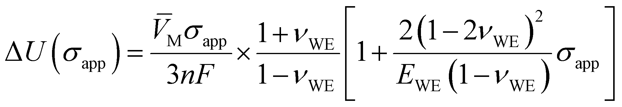
 . Since the quotient containing νWE is on the order of 1 and σapp/EWE < 10–3 typically, the deviatoric part should be approximately 0.1% of the hydrostatic part or less. Interestingly, eqn (5) produces ΔU =


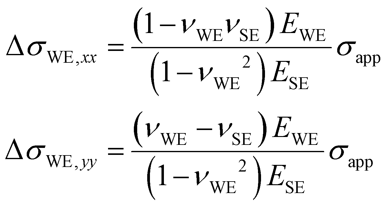
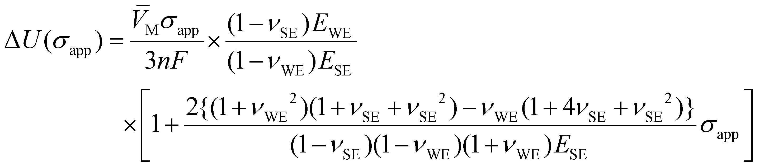
 , where the quotient involving ν's is on the order of 1. Given σapp/ESE < 10–3 typically, the deviatoric part again reduces only to approximately 0.1% of the hydrostatic part or less. It is emphasized that this equation is only accurate when the SE strains remain unaffected by the presence of the WE. This is an idealized assumption and incongruence would be present in reality, especially when the WE is relatively stiff compared to the SE (the interfacial bonding might be compromised in this case, as well). Thus, the accuracy of eqn (10) is expected to decrease as EWE increases, which is demonstrated numerically in Section 4.2.


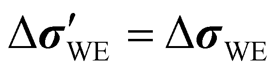 . Similarly, εWEh = 0 and
  with εWE,zz = 0. Incorporating these into eqn (2), ΔU becomes
 as outlined in eqn (2), averaged across the evaluation plane just above the WE/SE interface. The horizontal dashed lines show the analytical values that obey the no-strain assumption in eqn (5). Evidently, the difference between the two is small when EWE ≈ 7 GPa (EWE/ESE ≈ 0.05) but increases at both smaller and larger values of EWE. When EWE < 3 GPa (EWE/ESE < 0.02), eqn (5) is not relevant because the small-strain assumption does not hold for the σapp values modeled. When the SE and WE become comparably stiff, the validity of the no-strain assumption diminishes quickly, as evident in Fig. 3(c); while the analytical expression for the main strain component εWE in eqn (21) works well across the EWE range evaluated (see Fig. 3(b)) and the simulated shear strains remain small (less than 0.1% of εWE,zz), the normal strains increase noticeably. As a result, the error in
 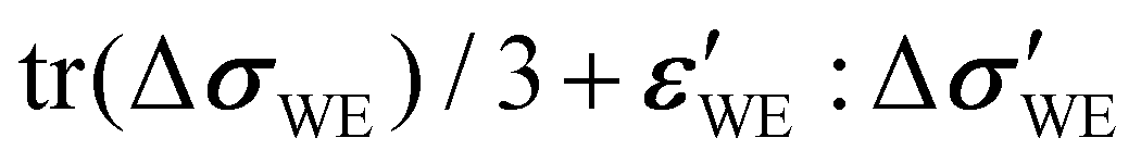 grows to 11% of the analytical value when EWE/ESE = 0.67 and 15% when EWE/ESE = 2 for all three σapp values. Although not constant, the error range is narrow, so a correction factor of f = 1.13 may be introduced to eqn (5) for WE/SE systems whose elastic-modulus ratio lies in the range 0.67 ≤ EWE/ESE ≤ 2.7. This correction should apply well to the systems made up of the materials listed in Table 1, where the combination that generates the largest elastic-modulus ratio is NMC-111/LiPON with EWE/ESE = 2.6. The use of constant f is further corroborated by the fact that the difference in Poisson's ratio between LCO and NMC-111 (0.24 and 0.25, respectively) is small, and so is the difference between LLZO and LiPON (0.257 and 0.27, respectively).


 is used, where
  is the surface-normal vector.
 (
( is the surface-normal vector) is used as the stress descriptor, as Herring30 and Ganser et al.18 suggested, ΔU in red in Fig. 4 ensues for LCO at α = 0.5. Clearly, the voltage response is exaggerated compared to the solid black line calculated from eqn (5); σn produces ∂ΔU/∂σapp 63% larger than the one based on the full stress–strain tensor treatment even after incorporating the correction f = 1.13. Again, the implications of this difference may be significant when calculating the interfacial-current-density distribution.
 that affects ΔU is shown in Fig. 5(a), as well as what the analytical expression in eqn (10) predicts as dashed lines. To recapitulate, eqn (10) was derived for a perfectly strain-matched interface with EWE ≪ ESE, such that the SE strains stay independent of the presence of the deposited WE. Because the external stress on the WE is administered via the SE, the stress magnitude the WE experiences is significantly reduced compared to |σapp|. Hence, the linear-elasticity assumption holds over a wider EWE window than in scenario I. Clearly, the agreement between the analytical expression and numerical solutions is good, as long as EWE < 30 GPa (EWE/ESE = 0.2). However, the discrepancy between the two grows as the WE becomes stiffer;
  is reduced by 22% relative to eqn (10) when EWE/ESE = 0.67 (EWE = 100 GPa) but as much as 47% when EWE/ESE = 2.7 (EWE = 400 GPa) for all three σapp values. Therefore, a correction factor 0.53 ≤ f ≤ 0.78 is necessary when using eqn (10) for practical experimental systems.
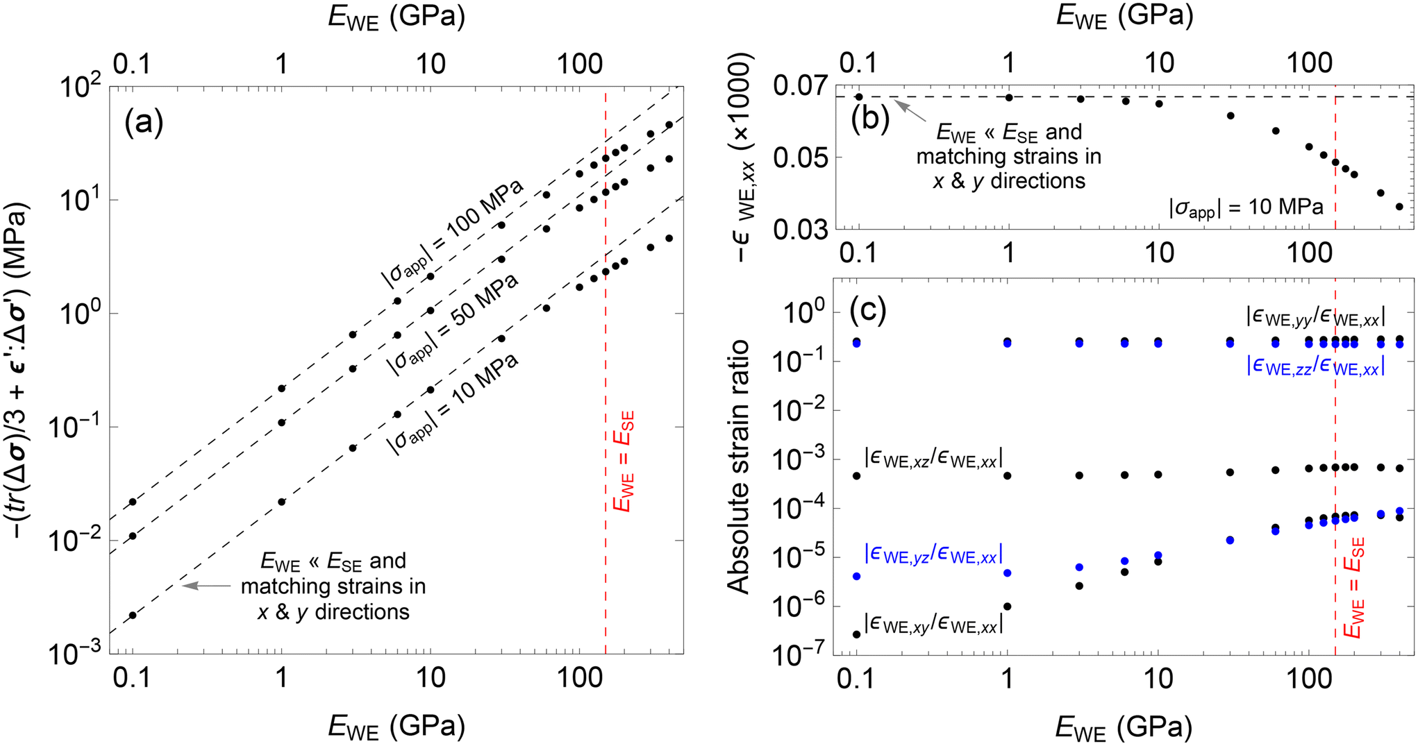
 grows noticeably with increasing EWE. Nonetheless, f = 0.66 (this corresponds to the numerical result at EWE = 200 GPa in Fig. 5(a)) is appropriate for LCO and NMC-111 deposited on LLZO, which is incorporated into eqn (10) to plot ΔU in Fig. 6(a). The quadratic behavior in ΔU is clearly insignificant and the square bracket in eqn (10) can be safely discarded. The same is observed when LLZO is replaced with LiPON, as Fig. 6(b) illustrates. Note that LiPON is less stiff than LLZO (i.e., ELiPON < ELLZO) and therefore elevates ΔU because of the factor EWE/ESE present in eqn (10). However, the full effect of EWE/ESE is dampened because the deviation from the EWE ≪ ESE assumption is larger for LiPON (f = 0.53) than for LLZO (the correction factor f = 0.53 for LiPON is based on the EWE = 400 GPa result in Fig. 5(a), which has EWE/ESE = 2.7. The same ratio for NMC-111/LiPON is 2.5, which is close enough.).
 is used, where
  is the surface-normal vector.
 , is plotted in Fig. 7(a); circular markers indicate numerical results while dashed lines correspond to the analytical expression in eqn (14). Contrary to the expectation, the |σapp| = 10 MPa simulation results are about 40% higher than the analytical expression in the lower EWE range. This is because the simulated hydrostatic stress tr(ΔσWE)/3 does not exactly amount to zero; normal stresses σWE,xx and σWE,yy do not nullify each other completely when added, and the plane-stress condition (ΔσWE,iz = ΔσWE,zi = 0; the i = z case is of specific concern here) is not exactly met. In particular, the COMSOL-generated tr(ΔσWE)/3 for |σapp| = 10 MPa is comparable in size to
  , hence the deviation in Fig. 7(a) is noticeable. In contrast,
  is more dominant for |σapp| = 50 and 100 MPa, and the numerical and analytical results align well, at least up to EWE = 30 GPa. Beyond this point, the difference between the two grows steadily as EWE approaches and surpasses ESE. This trend is also reflected in the x-direction normal strain εWE,xx in Fig. 7(b). Nevertheless, the strains retain the relative sizes eqn (12) prescribes, as Fig. 7(c) shows.

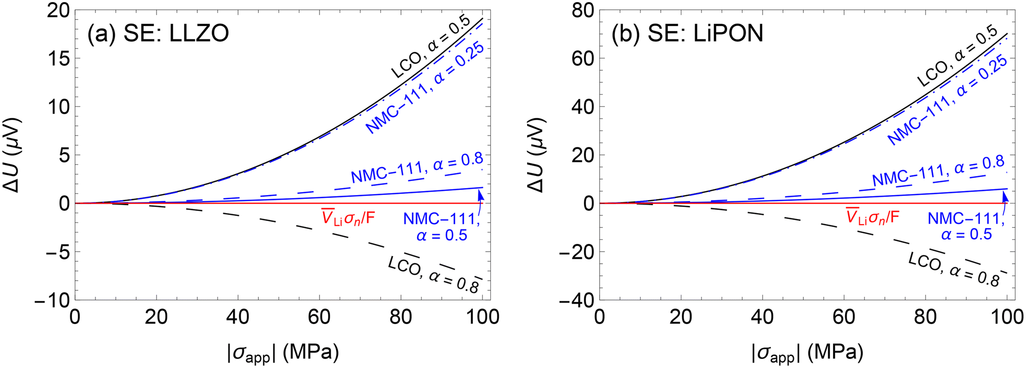
 is used, where
  is the surface-normal vector.


 , as below.

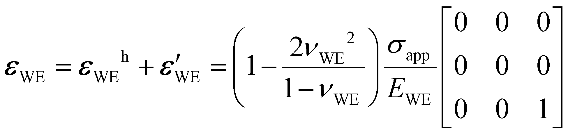
 parts.

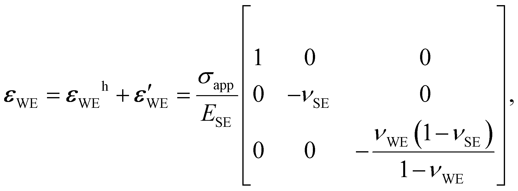
 parts become
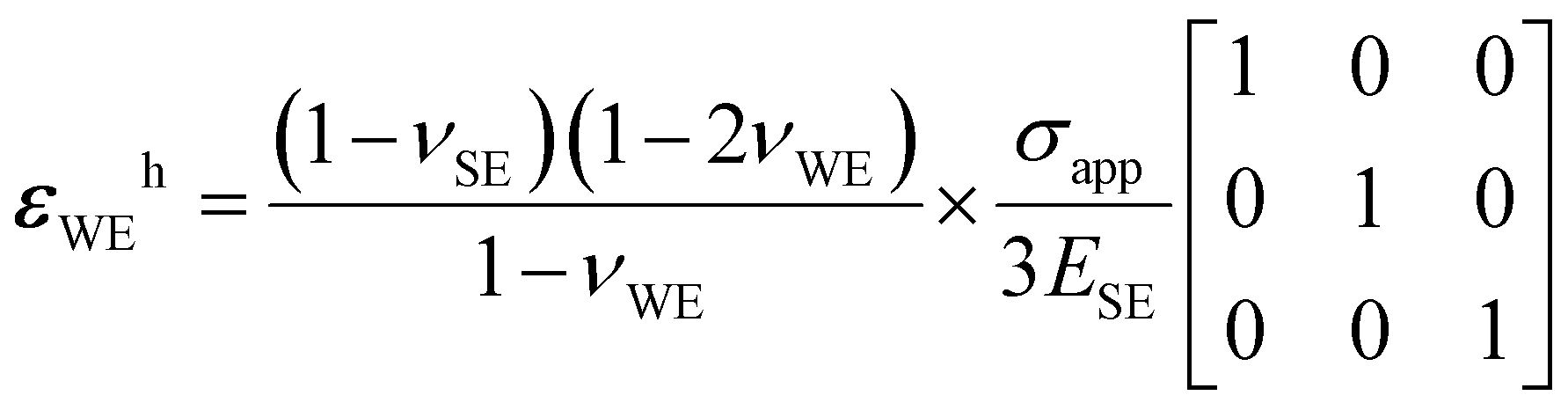


 produces

 to obey the standard sign convention in mechanics.