
 Open Access Article
 This Open Access Article is licensed under a Creative Commons Attribution-Non Commercial 3.0 Unported Licence
ArcaNN: automated enhanced sampling generation of training sets for chemically reactive machine learning interatomic potentials†
Rolf
David
 *,
Miguel
de la Puente
,
Axel
Gomez
,
Olaia
Anton
,
Guillaume
Stirnemann
* and
Damien
Laage
*
*,
Miguel
de la Puente
,
Axel
Gomez
,
Olaia
Anton
,
Guillaume
Stirnemann
* and
Damien
Laage
*
PASTEUR, Département de Chimie, École Normale Supérieure, PSL University, Sorbonne Université, CNRS, 75005 Paris, France. E-mail: rolf.david@ens.psl.eu; guillaume.stirnemann@ens.psl.eu; damien.laage@ens.psl.eu
First published on 30th October 2024
Abstract
The emergence of artificial intelligence is profoundly impacting computational chemistry, particularly through machine-learning interatomic potentials (MLIPs). Unlike traditional potential energy surface representations, MLIPs overcome the conventional computational scaling limitations by offering an effective combination of accuracy and efficiency for calculating atomic energies and forces to be used in molecular simulations. These MLIPs have significantly enhanced molecular simulations across various applications, including large-scale simulations of materials, interfaces, chemical reactions, and beyond. Despite these advances, the construction of training datasets—a critical component for the accuracy of MLIPs—has not received proportional attention, especially in the context of chemical reactivity, which depends on rare barrier-crossing events that are not easily included in the datasets. Here we address this gap by introducing ArcaNN, a comprehensive framework designed for generating training datasets for reactive MLIPs. ArcaNN employs a concurrent learning approach combined with advanced sampling techniques to ensure an accurate representation of high-energy geometries. The framework integrates automated processes for iterative training, exploration, new configuration selection, and energy and force labeling, all while ensuring reproducibility and documentation. We demonstrate ArcaNN's capabilities through two paradigm reactions: a nucleophilic substitution and a Diels–Alder reaction. These examples showcase its effectiveness, the uniformly low error of the resulting MLIP everywhere along the chemical reaction coordinate, and its potential for broad applications in reactive molecular dynamics. Finally, we provide guidelines for assessing the quality of MLIPs in reactive systems.
1 Introduction
The advent of artificial intelligence has revolutionized many fields of science, and machine learning has become an essential part of the scientific toolbox. In computational chemistry, machine-learning interatomic potentials (MLIPs) now offer an attractive method that combines accuracy and efficiency for calculating atomic energies and forces, which are the computational bottleneck when running molecular simulations. They have already led to remarkable success, ranging from the simulation of very large-scale systems1 to phase diagrams and transitions,2–4 metallic melts,5 interfaces,6–9 proteins in explicit solvent,10 and chemical reactions.6,11–20MLIPs provide a very high-dimensional fit of the potential energy surface (PES) of the system of interest, mapping the configuration space onto the potential energy. Most of the computational cost is incurred a priori during the training of the model on a dataset that spans the range of important molecular structures.21–26 The subsequent trajectory propagation then involves a much less expensive evaluation of forces with these potentials. This therefore contrasts with other molecular dynamics methods which determine forces on-the-fly via costly calculations involving, e.g., electronic structure determinations, that need to be repeated for each configuration encountered along the trajectory.
Over the years, a considerable effort has been devoted to the optimization of algorithms and network architectures, ranging from kernel-based methods25,27–29 to high-dimensional neural networks and their many flavors.30–46 As a result of these recent developments, MLIPs now offer an attractive alternative to DFT-based47,48 and reactive force field49 molecular dynamics simulations. While their computational cost is only moderately larger than that of classical force fields, they can be trained on high-level reference electronic structure calculations that provide much greater accuracy than empirical force fields. Their efficiency is thus many orders of magnitude greater than that of DFT-based simulations.
However, while recent advances have considerably optimized the architecture of MLIPS and their descriptors, dataset construction – another critical aspect affecting the quality of their energy and force predictions – has not been as extensively explored. Indeed, the training dataset should sample all typical configurations that will be encountered during the simulation, while avoiding redundancies.
Different strategies have been adopted for the construction of the training dataset, depending on the type of processes to be simulated and on the available data. In the first approach, the MLIP is trained only once, on a large collection of already available structures. This is the case, for example, with the general-purpose potentials ANI34,35 and MACE,50 which are trained on a large dataset of chemically diverse organic molecules in their equilibrium geometries. The resulting potential can then successfully describe the equilibrium fluctuations of a wide range of compounds in the gas phase. However, larger geometric distortions that exceed the amplitude of thermal fluctuations are not included in the training dataset and are likely to be poorly described by the MLIP.
A type of active learning approach based on successive iterations, named concurrent learning,51 has thus been proposed. Starting from an initial dataset, a first generation of MLIPs is simultaneously trained. The latter are then used for exploration of the potential energy surface via unbiased molecular dynamics simulations, possibly under various temperature and pressure conditions. In the configurations that are encountered, the quality of the MLIP prediction is estimated using a query-by-committee approach,52 which measures the deviation among the predictions of the assembly of potentials that were trained on the same dataset (but with different random initializations). Configurations in which the prediction uncertainty between the committee is large are then labeled with the reference calculation method and added to the training dataset for the next iteration of training and exploration. This approach is, for example, successfully implemented in DP-GEN53 and expanded in ChecMatE.54 We also note that recent uncertainty-aware and uncertainty-driven techniques have emerged as powerful tools for enhancing the accuracy and efficiency of MLIPs.55–59 By calculating the uncertainty of the MLIPs compared to the reference method, selecting configurations with high uncertainties, and possibly biasing the exploration of configurations toward poorly described regions, these approaches optimize the learning process, leading to more reliable and robust MLIPs, particularly in materials science. Other recent strategies, such as data distillation,60 have started to address the key component of constructing the training dataset.
However, a particular challenge is posed by chemically reactive systems, which require an accurate description of the energies and forces everywhere along the chemical reaction coordinate, including in the vicinity of high-energy transition states that are very rarely sampled spontaneously. This difficulty is well known,61 and has started to be addressed by some initial efforts. A recent study62 has proposed a general-purpose reactive MLIP in condensed phases trained on a dataset including configurations collected over a wide range of temperature and pressure conditions. Although this potential was shown to be successful for a number of chemical transformations, its exploration remains limited by the regions of the PES accessible via temperature and pressure changes, which implies that it is not adequate for chemical reactions with large energy barriers. Another effort63 specifically sampled reaction pathways but was limited to reactions in the gas phase. In a different approach, the training dataset can be enriched with configurations generated by enhanced sampling techniques,64 by performing random infinitesimal displacements,65 or by a combination of transition tube and normal mode sampling.66 In a very recent study, a combination of uncertainty-driven dynamics and enhanced sampling was proposed to address reactivity at solid interfaces.67 All these strategies aim to explore the high-energy regions of the PES. However, there is still a crucial lack of standardized procedures. A set of uniform and consistent protocols would be needed to ensure that the training is easily reproducible, with proper bookkeeping of every file and parameter, as well as a computational platform and workflow to support this. Currently, each user must either manually or semi-automatically implement their own strategy, which becomes increasingly tedious for more complex systems, as constructing a reliable dataset typically involves many iterations.
Here, we address this major challenge for the efficient simulation of condensed phase chemical reactions. We present ArcaNN, a comprehensive framework for generating training datasets for reactive MLIPs. It combines a concurrent learning approach for the controlled convergence of the potential and a wide range of advanced sampling techniques for exploring the chemically relevant configurations, including high-energy geometries. The exploration dynamics can be performed with either classical or quantum nuclear dynamics. These successive steps are integrated into an automated approach that includes training, extended exploration, new configuration selection and associated energy and force calculations at the reference level (labeling) steps, while keeping records so that the procedure can be easily documented and replicated.
In the following, we first summarize the main steps of concurrent learning for MLIPs and describe the ArcaNN code, its architecture, and the different steps involved in the iterative training dataset generation. We then illustrate its capabilities on two paradigm reactions: a nucleophilic substitution in solution and a Diels–Alder reaction in the gas phase. We finally provide some concluding remarks about the applications and future developments of our code.
2 Design of neural network interatomic potentials: overview
The objective of MLIPs, represented in Fig. 1A, is to approximate the potential energy surface (PES) of a system. For details regarding the different types of MLIP architectures, the training and choice of descriptors for the atomic environment, we refer the reader to excellent reviews,68–74 of which we provide a brief overview below. | ||
| Fig. 1 (A) Schematic representation of a neural network potential (NNP) that approximates the potential energy surface (PES) of a system. With a molecular structure as input, the NNP predicts the energy and forces of the system. (B) Schematic representation of the iterative training of NNPs using a concurrent learning loop. During training, several NNPs are trained on a dataset of molecular configurations, each labeled with their corresponding energies and forces. During exploration, they are then used to run MD simulations and the selection phase assesses whether there are new candidates to be labeled to expand the datasets. The loop between training, exploration, and labeling can be repeated multiple times until there are no more candidates and the NNP is then deemed ready for production. In ArcaNN, the exploration phase is improved by the use of enhanced sampling techniques to explore the chemical phase space (C) and the possibility to perform path-integral MD simulations (D). This allows the iterative enrichment of the dataset, leading to a complete description of the chemical reactivity (E). | ||
MLIPs have been developed based on different types of architectures, including artificial neural networks and kernel-based methods.25,27–29 A breakthrough in neural networks potentials (NNPs) came from the high-dimensional neural networks (HDNNs) introduced by Behler and Parrinello.30 The total energy of the system is decomposed into a sum of atomic contributions, which are assumed to exclusively depend on the local atomic environment encoded by a descriptor that satisfies the required PES invariances. Two key advantages of this scheme and of this locality approximation are their computational efficiency and the possibility to extend these neural network models to arbitrarily large systems. HDNNs with local descriptors based on a cutoff radius around each atom are used in several implementations, including BP-NNP,31–33 ANI,34,35 and DeePMD.36,37 Other MLIPs use the same atomic decomposition of the total energy but employ invariant message-passing neural networks (MPNNs)75 for their descriptors; these implementations include, e.g., DTNN,38 SchNet,39 PhysNet,40 and HIP-NN,41 which can access non-local information beyond the cutoff radius. Recent improvements include the use of equivariant, atom-centered, message-passing neural networks, like NequiP42 and its evolution Allegro,43 which have been suggested to provide an improved accuracy compared to local approaches, and to remove the limitations on accessible length scales. Finally, local models can also be extended by adding higher-order terms describing long-range effects and interactions.44–46,76,77
NNPs are trained using a supervised learning approach, on an ensemble of molecular structures, each labeled with their corresponding energies and forces. They usually demonstrate excellent accuracy in interpolating, i.e., predicting energies and forces for new configurations close to those seen during their training. However, this accuracy drops dramatically when extrapolating to configurations not seen during training, which is a key issue in machine learning models. For molecular dynamics simulations, this implies that if the trajectory ventures outside of the training dataset region, the NNPs will typically lead to unphysically large forces that abruptly terminate the simulation.
This issue can be addressed by identifying all relevant configurations a priori, for example, from an extensive sampling with a long simulation. However, this requires the ability to calculate the energies and forces during this long trajectory and necessitates, for example, ab initio molecular dynamics (aiMD). This solution is not practical since sampling with aiMD is computationally demanding, especially when the configurational space to be mapped is large. In addition, propagating long trajectories with good accuracy for the force calculations is precisely the objective of NNP-based simulations.
To address this situation where the volume of unlabeled data can be large but the cost of labeling is high, an iterative construction of the training dataset inspired by the concept of active learning78 was proposed to navigate through the data, gather feedback, and proactively seek labels for data points that are marked as requiring further attention. This concurrent learning approach,51,53 illustrated in Fig. 1B, involves three main steps: exploration, labeling, and training. These steps are repeated until convergence, which can be estimated using various descriptors and criteria.
However, exploration trajectories are usually propagated without any bias in the configurational space, and, as a consequence, chemical reactions with a free-energy barrier exceeding a few times the thermal energy do not spontaneously occur on the timescale of these simulations. An additional limitation is that during a reactive trajectory, the time spent in the transition state region is very limited. This unbalanced sampling therefore contrasts with the objective of achieving uniform sampling along the reaction coordinate to ensure that the error is low everywhere along the reaction path. Another limitation is that chemical reactions are rare events, and a given reactive trajectory between reactant and product regions is often short-lived (on the picosecond timescale). Finally, another difficulty is that for systems where several reaction pathways are in competition,14,15 we would like to sample all pathways and not only the minimal free energy one.
In order to better sample high free-energy barriers, enhanced sampling simulations are necessary. Examples include, but are not limited to, umbrella sampling,79 metadynamics80 and its variants,81,82 which have already been successfully applied in the context of data generation for NNPs.6,8,13–15,20,64,83 Generally, these approaches require identifying a set of collective variables (CVs) to bias the exploration trajectories, or setting up multiple enhanced sampling simulations covering numerous CVs to ensure that the reaction pathway is sampled adequately.
An important limitation in the current state of the art is therefore that users must either resort to a nano-reactor approach,62 which sacrifices control over specific reactivity and pathways, or they must manually set up numerous enhanced sampling simulations, which are both tedious and time-consuming. This is the limitation addressed by ArcaNN. It provides a comprehensive, flexible and automated workflow to generate datasets to train reactive NNPs while recording all the steps leading to the construction of the datasets, which can thus be easily shared and reproduced, a step towards meeting the FAIR principles84 for research data.
3 Streamlining the construction of a reactive dataset with ArcaNN
3.1 Concept
ArcaNN is a comprehensive framework, interfaced with other neural network, molecular simulation, and quantum calculation software for training NNPs, propagating trajectories, and labeling new configurations. ArcaNN allows the sampling of the chemical phase space of a given reaction (encompassing reactants, products, intermediates, and transition states with the solvent treated in a reactive manner) to adequately and efficiently build a dataset that can be used to train NNPs.The workflow combines the concurrent learning approach with enhanced sampling techniques, as shown in Fig. 1C. Starting from an easily generated dataset of structures in the reactant and product regions, ArcaNN supervises the simulation of either classical or path-integral swarms of short biased dynamics. The dataset is progressively enriched with representative structures along the reaction pathways, on which generations of NNPs are iteratively trained and used for successive rounds of exploration. This approach not only makes more efficient use of computational resources compared to an equivalent biased initial ab initio trajectory but also provides a greater number of uncorrelated samples, leading to more accurate NNPs.
3.2 Overview of the code and definitions
ArcaNN is a Python 3 package designed in a modular fashion to facilitate its extension, modification, and the integration of new features, such as interfacing with new software or types of MLIPs. The current version of ArcaNN is interfaced with the following programs:• CP2K85 for labeling.
• DeePMD-kit86,87 for training the NNPs.
• LAMMPS88 or i-PI89 for exploration using the DeePMD NNPs, both in combination with Plumed90 for enhanced sampling.
ArcaNN maintains a clear and easily readable record of the workflow. This framework offers great flexibility at each workflow step, including the full range of quantum chemistry methods available in CP2K and the diverse enhanced sampling techniques and CV definitions offered by Plumed. Users can also choose to explore any number of systems. As detailed below, these correspond to a combination of MD parameters, thermodynamic conditions, and chemical compositions.
ArcaNN is specifically designed for High-Performance Computing (HPC) clusters with CPU and GPU resources, exploiting them in an embarrassingly parallel fashion. It utilizes VMD91 for trajectory manipulation in the DCD format and Atomsk92 for converting LAMMPS data files to and from the XYZ format.
From the initial datasets and user-provided files, ArcaNN oversees the creation of necessary files and folders for the interfaced programs and submission scripts for HPC resources. It manages the training of NNPs, the exploration of phase space, and the labeling of configurations, and it iterates these steps until the NNPs accurately describe the targeted reactivity of a given system. While requiring minimal intervention, ArcaNN gives users full control over the iterative process through a series of steps and phases whose parameters can all be set or modified before execution. We now describe, in the next 4 sections, the concepts of steps, phases and systems around which ArcaNN is organized as well as address what user files are needed to start the ArcaNN procedure.
 | ||
| Fig. 2 The ArcaNN's architecture divided into five main modules corresponding to the successive steps: initialization, training, exploration, labeling and an optional test module. Each module is divided into several phases that are executed in sequence with user intervention, either proceeding from top to bottom within the same module or by following the arrows between modules. Phases with an asterisk (*) invoke a scheduler to submit the resource-intensive jobs to the HPC, while the others are almost instantaneous and are executed on the login node. In green are the phases that are mandatory, in orange are the optional phases and in blue are the phases that are mandatory only in the case of path-integral MD simulations. | ||
ArcaNN requires minimal user input beyond the user files detailed below and a comprehensive manual accompanied with example files is provided on the GitHub repository.93 ArcaNN generates all the necessary files and directories for the workflow; its operating parameters are set to default values unless tuned by the user as needed. Each time a phase is executed, two JSON files are created. One is the default JSON (default_input.json), where all the default values used are stored, providing guidelines for the user. The other JSON (used_input.json) stores all the values used for this specific phase and is created only if the phase is successfully completed, ensuring the traceability of the values used for each phase in each iteration.
Any default value can be modified through the user-provided JSON file (input.json). For example, if a user executes the training prepare phase but wants to change the learning rate, they can provide an input.json containing only the learning rate value. The user will then relaunch the training preparation phase and the input.json values will be taken into account. In this scheme, the priority is given to user values, then to values used in the previous iteration or auto-calculated from the previous iteration, and finally to the default values. This is useful, for example, if the user wants to change a parameter in the exploration; this change will be carried over to the next iteration without the need to provide an input file again. If a phase fails, an explicit message will be displayed, and the user will have to fix the issue before re-executing the phase.
Another feature of ArcaNN is its flexibility: the practical number of systems a user can define depends on their available HPC resources, rather than being constrained by the ArcaNN methodology itself. Importantly, the systems do not need to have the same chemical composition. For instance, one might include a system composed of one set of reactants and another that simulates a higher concentration with two sets of reactants, possibly within a larger solvent box. Furthermore, systems can be constructed from different molecular configurations, such as one with reactants and products, and another with reactants and different products, representing competitive reactions, or even varying solvents to explore a wide range of chemical environments.
To control the use of HPC resources, ArcaNN uses a machine.json file where HPC resources are identified through a keyword, and the configuration outlines various attributes of the HPC machine, such as the job scheduler, the maximum number of jobs in the queue, and the maximum scheduler array size. Furthermore, it provides specifics for project or task setups within this HPC resource under sub-keyword, including names for projects and allocations, architecture type, and a designated partition for job queuing as well as valid tasks for execution. Importantly, it facilitates the incorporation of multiple HPC machines, for executing specific tasks on GPUs and others on CPUs. An example of a machine.json file can be found in Fig. S2,† and more details can be found in the documentation on the GitHub repository.93
A second set of files required to initiate the training process corresponds to the initial training dataset. In the current version of ArcaNN, these datasets, which include atomic configurations, energies, forces, and virial tensors, should be formatted in the DeePMD-kit format.
We pause to provide some useful guidelines on how to generate these datasets. They are typically obtained from short aiMD simulations. To enhance the training efficacy, it is recommended that these datasets contain as many uncorrelated configurations as possible, primarily spaced over time. As a rule of thumb, configurations spaced by 20 fs provide a good starting point.
If the aiMD simulations are performed at the same DFT level as the desired reference for the NNPs, the user can directly supply the associated energies, forces, and virial tensors. However, to improve the computational efficiency, a recommended practice is to conduct the aiMD at a less computationally demanding level of theory before executing the reference level calculations solely on the selected configurations. This approach is advantageous, as the geometries generated by a cheaper theory level are usually reliable, but the energies and forces are not as good as those provided by a higher level description. For instance, initial simulations can employ a GGA functional with a minimal basis set, while subsequent reference calculations use a higher level GGA or hybrid functional accompanied by a larger basis set. Alternatively, users may opt for even more cost-effective calculations, such as semi-empirical methods like DFTB2 (ref. 95 and 96) or GFN2-xTB,97 and then perform the reference calculations on the selected configurations. ArcaNN offers flexibility in managing the initial datasets, including the option to discard them if their energy distribution significantly deviates from that of the datasets constructed during the iterative training process. Moreover, it accommodates the addition of extra datasets, independent of the initial and iterative ones, at any stage of the training. This feature is particularly useful if users provide datasets from other sources or systems that they wish to incorporate. For example, as initial datasets, users can provide datasets sampling the reactants, the products, and the pathways from reactants to products, as well as datasets from products to reactants obtained from aiMD.
3.3 Workflow
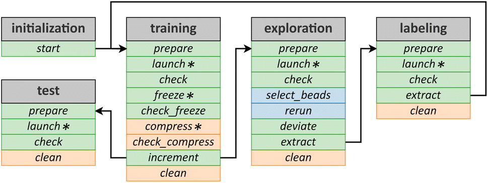
As shown in Fig. 2, the workflow is divided into five main steps: initialization, executed once at the beginning of the workflow; training (of the NNPs); exploration (swarms of enhanced sampling trajectories with selection of candidates); labeling (labeling the new candidates with the reference method), which are integral parts of the concurrent learning cycle; and testing, which is optional and can be used to assess the training of the NNPs. A recurrent phase is the optional clean phase that can be executed at the end of each step to remove unnecessary files, such as temporary files created by ArcaNN and redundant files. The other phases are specific to each step, and are detailed below. The next sections will describe the different steps and phases of the workflow.It is important to note that the execution of these steps is not automated; each phase must be manually initiated by the user. While resource-intensive tasks, such as training, exploration, and labeling, are submitted to the HPC queue manager (e.g., SLURM) for execution, ArcaNN does not provide automatic updates on their completion. Instead, the user should manually check the status of these tasks in the corresponding check phases before moving on to the next phase. This method requires more user involvement but ensures precise control over the workflow and facilitates troubleshooting and adjustments based on intermediate results.
When the set-up is complete, the user can proceed to the initialization step which involves a single phase, start, ensuring the presence of all the user files. This step corresponds to the creation of the initial training folder and the control directory, where the JSON files are saved. Additionally, it locates the initial datasets and tags them for the first training step. This phase also reads all the names of the LAMMPS datafiles provided by the user and then automatically creates the list of systems that ArcaNN will use for the exploration and labeling steps. In this step, the user can also choose the number of NNP models to train for the committee, which is set to three by default. After this step is successfully completed, the user can proceed to the training step.
During the training step, a committee of several NNPs are trained based on the existing structures in the current dataset. This step is divided into the following phases: prepare, launch, check, freeze, check_freeze, compress, check_compress, increment and clean, with an overview of the phases represented in Table 1.
| Phase | Description | Status |
|---|---|---|
| Prepare | Create necessary folders and files for the training of the NNPs (and the number of NNPs to be trained) | Mandatory |
| Launch | Submit training jobs | Mandatory |
| Check | Check if the training jobs are successful | Mandatory |
| Freeze | Freeze the NNPs | Mandatory |
| Check_freeze | Check if the freezing is successful | Mandatory |
| Compress | Compress the NNPs | Optional |
| Check_compress | Check if the compression is successful | Optional |
| Increment | Update the temporary number | Mandatory |
| Clean | Remove unnecessary files | Optional |
The prepare phase will create the necessary folders and files for the next phase. It will copy the datasets, and the dptrain.json (which is the DeePMD-kit input) file to the training folder and we refer to the documentation of the DeePMD-kit87 for this file and the associated hyperparameters. In this phase the user can define, for example, the learning rate, the number of steps, and the machine keyword for the job scheduler parameters (for more details, see the documentation on the Github repository93).
All the subsequent phases do not require further user inputs. After the prepare phase, the launch phase will submit the training jobs to the HPC cluster. The check phase will check if the training is successful, and will provide guidelines about the training duration that can be used for the next iteration. The next phase, the freeze phase, will submit jobs to the HPC cluster to convert (i.e., freeze) the models from their trainable parameters (e.g., weights and biases) to constants and remove unnecessary training operations, enabling them to be efficiently used for inference (i.e., as NNPs predicting energies and forces), while the check_freeze phase will check the success of this operation. The compress phase will submit jobs to the HPC cluster to compress the models, and the check_compress phase will check the success of compression. The model compression98 is used to boost the efficiency of inference using three techniques: tabulated inference, operator merging, and precise neighbor indexing. This is optional, and the user can choose to skip this phase. The final phase is the increment phase, which updates the iteration number, concluding the active learning cycle by producing a new generation of NNPs (or the first one). Fig. S3† shows a typical JSON output from this step, located in the control folder and named training_ITERATIONNUMBER.json, which records the results of each phase. After the training step is successfully completed, the user can proceed to the exploration step.
The exploration step is at the core of the construction of a dataset using active learning in order to include representative structures potentially present along the reaction pathway(s). If the nuclei are treated classically, the current implementation calls LAMMPS for the exploration step, which is divided into the following phases: prepare, launch, check, deviate, extract, and clean. In the case of quantum nuclei, the exploration is performed using i-PI and is divided into the following phases: prepare, launch, check, select_beads, rerun, deviate, extract, and clean. The overview of the phases is represented in Table 2.
| Phase | Description | Status |
|---|---|---|
| Prepare | Create necessary folders and files for the exploration (per system) | Mandatory |
| Launch | Submit exploration jobs | Mandatory |
| Check | Check if the explorations are successful | Mandator |
| Select_beads | Select one random bead per configuration | Mandatory (PIMD only) |
| Rerun | Calculate the model deviation on those beads | Mandatory (PIMD only) |
| Deviate | Select new candidate configurations | Mandatory |
| Extract | Extract those configurations | Mandatory |
| Clean | Remove unnecessary files | Optional |
The prepare phase creates the necessary folders and files to run MD simulations for each system using the concurrent NNPs trained at the previous step. The user can tune the number of trajectories to be run for each NNP (default value of 2). For example, for six systems, three NNPs, and two trajectories per NNP, a total of nsystems × nNNPs × ntrajectories = 6 × 3 × 2 = 36 MD simulations will be prepared. Other tunable parameters include the timestep, the number of steps, and the machine keyword for the job scheduler parameters (see the complete list in the repository93).
The launch phase will submit the MD simulations to the HPC cluster, and the check phase will ensure the success of the simulations. If some simulations have crashed, the user can choose to skip them, or to force the selection of candidates along the stable part of the trajectory. Indeed, it is very common in the early iterations for simulations to crash before the end when encountering structures deviating significantly from those on which they were trained. However, they can still be used to enrich the training database. During this phase, while the MD engine will propagate the trajectory using one of the NNPs, forces are also calculated on-the-fly with the other NNPs. For a given configuration x, the maximal deviation on the atomic forces, maxi[εFi(x)] is calculated as the maximal deviation on any atom i within the configuration. The deviation of the atomic forces on atom i for configuration x, calculated over N NNPs, is defined as:
 | (1) |
During the deviate phase, configurations are classified into three categories. Set A includes configurations that closely resemble parts of the training dataset and show minimal variance in the forces, maxi[εF,i(x)] ≤ σlow. Set B includes configurations that present a significant variance in forces, σlow < maxi[εF,i(x)] ≤ σhigh. Finally, set C includes configurations that are considered as potentially non-physical and unreliable with maxi[εF,i(x)] > σhigh. Configurations within set B will be referred to as candidates and will be labeled and added to the training dataset whereas configurations in set C will be discarded. The user can modify the values of σlow and σhigh, defining the range of set B.
We pause to discuss some useful guidelines for these values, which have been derived from our own experience. We recommend using a σlow of about four times the value of the NNP RMSE, which is typically around 0.05 eV Å−1. Therefore, a value of 0.2 eV Å−1 is a good starting point. Next, σhigh can be set to four times this value, i.e., 0.8 eV Å−1. At the later stage of the iterations, the user can reduce these values to 0.1 eV Å−1 and 0.4 eV Å−1 in order to limit the number of selected configurations once the dataset becomes rich enough in reactive structures. A third value, σmax, acts as a threshold beyond which, even if configurations encountered afterwards during the dynamics drop below σhigh, they will still be discarded as the path to these configurations is deemed unphysical, with a default value of 1.0 eV Å−1. The user can also set the maximum number of candidates to select, which is set to 50 by default (for each system), and also set how many timesteps are ignored at the beginning of each trajectory to ensure proper decorrelation from the starting point.
The deviate phase also selects starting points for the exploration step of the next iteration. These are chosen to be the configurations with the lowest deviation in set B, or, in the absence of such candidates, as the last configuration of the dynamics (which belongs to set A). If no new candidate emerges due to simulations crashing, the starting points of the explorations of the next iteration will be the same as those in the current iteration. This ensures that the next starting points are either part of the training dataset (because they will be candidates belonging to set B) or already well described by the NNPs (set A). Users also have the option to always start from the same initial configurations, which can be useful at the beginning of the iterative cycle.
The extract phase then extracts from the trajectories the selected starting points and candidates for the next step by reading the list of indices from the deviate phase. As the retrieval process can be time-consuming (on the order of minutes, especially if the trajectory files are large), the selection of candidates is split into two phases: the first (vide supra) is fast as only the deviation files are read, and the user can fine-tune the parameters (the σ or the maximum number of candidates) and only then proceeds to the extract phase to process the trajectory files and retrieve the candidate configurations. Furthermore, users have the option to increase the number of candidates twofold by slightly shifting the positions of the atoms,65 either for a specific set of atoms or for all atoms. This process applies to all original candidates, resulting in a final number of candidates that includes both the original and the altered ones. This is done using the built-in function of Atomsk92 to disturb atomic positions by applying random translation vectors to atoms, while ensuring no global translation of the system and following a normal distribution function to generate new configurations. This can be useful when the exploration phase does not yield enough candidates or if the user wishes to explore a wider range of the phase space. Caution is emphasized, as the disturbed move is performed randomly and could lead to unphysical configurations, and can be also time-consuming if the number of candidates is large.
ArcaNN also offers the possibility to train the NNPs for nuclear quantum effects using RPMD and in that case, path-integral MD are run with i-PI. To have accurate NNPs to perform the RPMD simulations, they are trained on the beads and not on the centroids, as the NNPs will be used to compute forces on each bead. It is possible to use NNPs trained on PIMD simulations to perform classical MD simulations as the classical nuclei lie between beads; thus the NNPs can interpolate the computed forces (and energies), but the beads cannot be reliably extrapolated from training with classical nuclei, and thus caution is advised in the latter case. To achieve this, the exploration step has two new phases, select_beads and rerun. As i-PI does not allow multiple models to calculate the model deviation on-the-fly, the select_beads phase will randomly select one bead per MD step, and the rerun phase will run inference on the ‘trajectory’ to determine the deviation between the models using LAMMPS. The user can also mix classical and path-integral MD simulations, with one set of systems for each type of simulation.
It is important to note that most of the exploration (during the prepare phase) and selection (during the deviate phase) parameters, as well as the possibility to create new perturbed configurations (during the extract phase), are set independently for each system, providing great flexibility to the user, who can either use the same values for all systems or set different values for each system. Identical to the training step, a JSON output is written, and an example is shown in Fig. S4.†
A key point is that if the previous iteration N results in a limited pool of candidates, ArcaNN dynamically adjusts the MD simulation lengths for the following exploration phase N + 1, aiming to increase the sampling. After the exploration step is successfully completed, the user can proceed to the labeling step.
The goal of this step is to generate labels for the candidates selected in the exploration step, which will then enrich the training dataset. This step is divided into several phases: prepare, launch, check, extract, and clean with an overview of the phases presented in Table 3.
| Phase | Description | Status |
|---|---|---|
| Prepare | Create necessary folders and files for the labeling of the candidates | Mandatory |
| Launch | Submit the labeling jobs | Mandatory |
| Check | Check if the labeling jobs are successful | Mandatory |
| Extract | Extract the labeled candidates | Mandatory |
| Clean | Remove unnecessary files | Optional |
As with the other steps, the prepare phase will ensure the creation of necessary folders and files to run the single-point calculations. A few options are available to the user besides providing the input files for CP2K, namely the number of nodes, the number of MPI processes per node, as well as the number of threads per MPI process. To improve efficiency, the single-point (SP) calculations are divided into two parts: the first SP calculation can be a quick and cheap calculation (e.g., GGA with a small basis set) to get an initial optimized wavefunction which will serve as a guess for the second SP calculation at the desired reference level of theory (e.g., GGA or hybrid-GGA with a large basis set). This significantly speeds up the labeling calculations.
The launch phase will submit the single-point calculations to the HPC cluster, and the check phase will ensure the success of the calculations (i.e., the convergence of the calculations). If a low-cost calculation does not converge, a warning is displayed; however, if the subsequent expensive calculation converges, the program continues. If the expensive calculation does not converge, an error is displayed, and the user will have to fix the issue before relaunching the phase, either by skipping the candidate or by manually relaunching the single-point calculations.
The extract phase will extract the molecular structure, energy, forces, box size, and, if present, the virial tensor from the single-point calculations and store them in the DeePMD-kit format as a new dataset. By convention, the files containing these new labeled structures are named sysname_XXX, where sysname is the name of the system and XXX is the iteration number.
As per the previous steps, a JSON file is written and is shown in Fig. S5.† After the labeling step is successfully completed, the user can proceed to the training step, completing the cycle.
| Phase | Description | Status |
|---|---|---|
| Prepare | Create necessary folders and files for the testing of the NNPs | Mandatory |
| Launch | Submit the testing jobs | Mandatory |
| Check | Check if the testing jobs are successful and concatenate the results in a JSON file | Mandatory |
| Clean | Remove unnecessary files | Optional |
The prepare phase will ensure the creation of the necessary folders and files to run the testing phase. It is important to note that here, the testing is performed on all datasets, including the initial, iterative, and extra datasets. This is not a validation of the NNPs, but a way to ensure that the NNPs are still performing well on all datasets. For a more in-depth validation, the user should provide a separate dataset that was not used for training. The launch phase will submit the testing jobs to the HPC cluster while the check phase will ensure the success of the testing jobs and record the results in a control JSON file (Fig. S6†).
4 Application to typical chemical reactions
In this section, we demonstrate the use and capabilities of ArcaNN in training NNPs on two examples: a nucleophilic substitution reaction in solution and a pericyclic reaction in the gas phase. These two reactions are selected as model test cases for which all the necessary files are provided; however, we stress that a prototype version of ArcaNN has been successfully used for more complex sequential reactions involving nucleophilic attack, nucleofuge departure and proton rearrangements.14,154.1 Nucleophilic substitution reaction
We focus on the SN2 reaction between chloromethane CH3Cl and a bromide ion Br− in acetonitrile CH3CN, represented in Fig. 3. This reaction together with other related SN2 reactions has already been studied using a range of methods including mixed QM/MM simulations and ab initio molecular dynamics.99–106 | ||
| Fig. 3 (A) Mechanism of the SN2 reaction between chloromethane and bromide ions. Collective variables used to bias or to monitor the reaction: (B) the distances between the carbon atom of the methyl group and the chlorine and bromine atoms, dC–Cl and dC–Br, respectively; (C) the angle α between the carbon atom of the methyl group and the chlorine and bromine atoms; (D) the angle ω between the plane containing the three hydrogen atoms of the methyl group (purple) and the plane containing the carbon atom of the methyl group and two hydrogen atoms (orange). | ||
The mechanism involves a single step wherein the Br− nucleophile attacks the chloromethane electrophilic carbon from the opposite side of the Cl leaving group. The nucleophilic attack and leaving group departure occur concurrently, leading to the inversion of the carbon center stereochemistry.
4.1.1.1 Initial aiMD dataset. We start from an exploration of the system in the reactant state (i.e., CH3Cl + Br−) using a classical force field. From this trajectory 20 snapshots were extracted with half of them having their bromine and chlorine atoms swapped. Using these as starting points, very short aiMD trajectories were propagated at the DFT BLYP-D3 level. By extracting structures that are as decorrelated in time as possible, we generated an initial dataset of 1000 configurations, which will be referred to as the aiMD training dataset (see Methods and the ESI†).
4.1.1.2 Iterative non-reactive datasets. We first performed iterations of the exploration, labeling, and training steps (Fig. 2). The goal was to enrich the dataset with structures not well predicted by a given iteration of the NNP, while not explicitly training for reactivity yet. In practice, we generated a number of systems that allowed scanning the diversity of arrangements between the two molecules in the reactant and product states. After 7 such iterations, we decided to stop this procedure, as the number of new candidates to be included in the dataset became negligible. We refer to each generation i of datasets (and their corresponding NNPs) as NRi (for non-reactive). These steps resulted in a modest enrichment of the initial dataset, with a total number of 1158 structures in NR7.
4.1.1.3 Exploration of reactive structures. Finally, we performed 5 iterations of the exploration, labeling, and training steps with now explicit exploration of structures along the reaction pathway. This was achieved using a variety of systems based on 1D or 2D OPES. We refer to each generation i of datasets (and their corresponding NNPs) as Ri (for non-reactive). These steps resulted in a significant enrichment of the initial dataset, with a total number of 2313 (1000 + 158 + 1155 structures) structures in R5. Although some OPES trajectories crashed during the exploration of reactive structures with intermediate datasets, simulations with R5 were found to be stable and we thus decided to stop the dataset construction and training after 5 steps (Fig. S7†).
We now discuss the benefits of the ArcaNN approach by comparing a variety of observables along the iterations. For this purpose, we first constructed a test dataset that is relevant for the chemical reaction by systematically generating 1210 structures along the reactive path between the reactant and product basins using Umbrella Sampling (US) simulations with the final R5 NNP (see Methods). Having a test dataset is critical to assess the quality of the training,107,108 and it is generally uniformly sampled along the entire phase space. To study a particular reaction, we believe that a test dataset of untrained structures uniformly sampled along the reaction pathway permits ensuring that the accuracy of the NNPs is constant for all relevant reactive structures. This is even more important if the reaction presents two pathways: both should be described with the same accuracy. Irrespective of the ArcaNN procedure, we also performed two types of enhanced sampling “production-like” simulations at each cycle with the resulting NNPs: US and OPES simulations. We tracked the occurrence of untrustworthy structures in the US simulations and, for both methods, the free-energy surfaces for the reaction. These are the metrics we used to determine the validity of the NNPs: the RMSE of the forces for an independent test set along the reaction pathway to ensure accuracy and the stability of the NNPs during enhanced sampling.
Fig. 4A shows the Root Mean Square Error (RMSE) of the force components in the training and test datasets at each ArcaNN cycle. Until the final iteration of the non-reactive dataset, we do not observe significant variations in the RMSE on the training datasets, suggesting that the NNPs train with similar accuracy, which is not surprising considering the limited augmentation of the training dataset during these iterations. However, these steps are essential to start mapping the chemical phase space, as the initial aiMD dataset contains a very inhomogeneous distribution of structures, with, for example, very few reactant configurations where CH3Cl and Br− are far apart (Fig. 4B).
 | ||
| Fig. 4 ArcaNN training for the SN2 reaction (A) histogram of the RMSE of the forces on the training dataset and the test dataset at each training cycle, with aiMD corresponding to the initial dataset, NR for each non-reactive ArcaNN cycle, and R for each reactive ArcaNN cycle. (B) Histogram of the percentage of all untrustworthy structures from the US calculations (where maxi[εF,i(x)] > 0.7 eV Å−1) with the NNPs obtained at each ArcaNN cycle. (C) Probability density of untrustworthy structures in the training datasets as a function of the absolute value of δd, with aiMD representing the initial structures, NR7 representing all 158 structures added during the non-reactive ArcaNN cycles, and R5 representing all 1155 structures added during the reactive ArcaNN cycles. (D) Free energy profile of the US calculations with the NNPs obtained at each ArcaNN cycle. | ||
We notice a clear gap between the RMSE on the training dataset and that on the test dataset that encompasses a lot of reactive structures on which these non-reactive NNPs have not been trained. However, even without the explicit inclusion of structures on the reaction pathway, the NNPs get better at extrapolating the corresponding forces, leading to a small but noticeable decrease in the RMSE on the test dataset.
When we start reactive cycles, the RMSE on the training dataset suddenly increases, while the error on the testing dataset decreases. This can be explained by the large number of new structures that are included in the dataset during the reactive cycles, especially close the transition state region (Fig. 4B). As the training dataset increases in size and diversity, overfitting on the initial structures is reduced, while simultaneously improving the description of the newly encountered higher energy configurations near the transition state, which were responsible of the poor initial performances on the testing dataset.
The only observation of the RSMEs can lead to deceptive conclusions about the necessity of iterations and the progressive exploration of the chemical phase space. Therefore, this should not be the sole aspect to consider when assessing the convergence and the quality of the NNPs for a given chemical reaction. For example, for each generation of NNPs, we report in Fig. 4C the fraction of structures encountered during 1D US simulations (such as those presented in Fig. 4D) that result in large deviations from the reference method. While the original aiMD NNPs appeared to yield reasonable RMSEs (Fig. 4A), they result in a significant fraction of poor predictions along the reaction pathway. During the non-reactive cycles, the NNPs get progressively better, with NR2 and NR3 that seem to be reliable. However, this further degrades again when continuing the non-reactive iterations, which seems surprising since the global RMSE on the test dataset keeps decreasing, although to a limited extent. This suggests that the non-reactive cycles here could probably have been stopped after the third iteration.
When starting the reactive cycles, the NNPs become more and more reliable when considering the fraction of untrustworthy structures (Fig. 4C and S7†), which goes to zero for the fifth iteration R5. However, things do not seem to significantly improve after R2. In Fig. S8,† we represent the RMSEs along the reaction coordinate for the aiMD, the NR7 and the R5 NNPs: one can see that at the final iteration, the RMSEs is constant for all structures encountered along the reaction pathway. The RMSEs for the R5 NNPs and the test dataset are reported in Fig. S9.† The RMSEs on the magnitude of the forces are similar for the training and test datasets with a value around 0.05 eV Å−1, whereas the RMSEs on the force components are equal and slightly lower, with values around 0.03 eV Å−1.
One key aspect that is overlooked in these considerations is the stability of the NNPs when running the actual simulations, especially so when using enhanced sampling methods. For example, when running the 1D US simulations for each generation of NNPs, many windows crash after a few tens to a few hundreds of ps. This is observed for all NNPs except the last one (R5). However, these simulations provide enough data to allow for overlap between adjacent windows along this collective variable, and the corresponding PMFs can be determined (Fig. 4D). Despite being unstable, the intermediate NNPs lead to free-energy profiles that do not exhibit major inconsistencies, although the barrier appears to be not quantitatively described when the aiMD or non-reactive NNPs are used. Strikingly, the transition state (TS) structure is not correct, being a carbocation, as in a SN1 mechanism (Fig. S10†). For more complex reactions involving several atom exchanges (for example, proton transfers in addition to a heavy atom exchange), it is expected that free-energy surfaces would not easily converge.
However, US simulations give seemingly physical results with non reactive NNPs for this specific case, which may fool the user into believing that subsequent optimization of the NNPs are not required. As already mentioned, the fact that all but the final R5 NNPs result in at least one non stable trajectory is already an indication that they should not fully be reliable. Long enhanced sampling simulations using, e.g., OPES appear as a more stringent test of the quality of these NNPs (see Methods for details).
For example, OPES simulations with NNPs from the R1 dataset crash after 44 ps while the one with the R3 dataset does not crash but starts becoming untrustworthy after 978.25 ps. When accounting for the bias accumulated until they crash or become untrustworthy, we can reconstruct free energy surfaces along the carbon–halogen distances (see Fig. 5), which are not correct at all and exhibit unrealistic basins. Only the final R5 NNP converges to a ΔG‡ equal to 14.74 ± 0.39 kcal mol−1 and a ΔG equal to 2.25 ± 0.44 kcal mol−1, similar to the values obtained from the US simulations with the same NNP (see below).
 | ||
| Fig. 5 Free energy surfaces for the SN2 reaction obtained from OPES simulations with the NNPs trained, respectively, on the R1 (A), R3 (B) and R5 (C) datasets. | ||
These results illustrate that the RMSE of the forces on a test dataset is not enough to ensure the validity of the NNPs. One must also check the stability of the NNPs during enhanced sampling simulations, because the explored pathways are not always the minimum free energy paths and US simulations with very high number of windows and good overlap can mask this instability. We recommend to use several types of enhanced sampling simulations to ensure the stability of the NNPs, ideally using a superset of those that will be used for the study of the reaction, especially when the reaction requires more than one collective variable for description.
We eventually illustrate how the final, stable R5 NNP can lead to quantitative and accurate information about this model SN2 reaction. In Fig. 6A, we show the free-energy profile along the asymmetric stretch of the carbon–halogen distances δd, together with the evolution of these distances and of the ω angle, indicating the Walden inversion. Fig. 6B–D show some joint probabilities of these key collective variables (CVs) throughout the reaction.
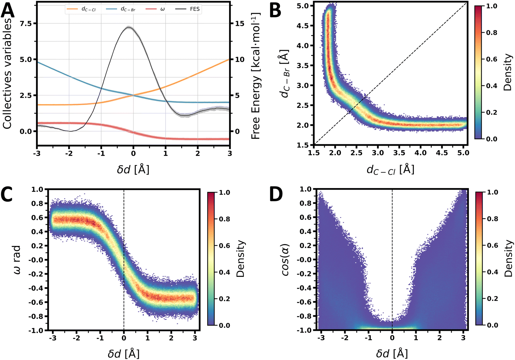 | ||
| Fig. 6 (A) Free energy surface of the SN2 reaction obtained from the US simulations with the NNP trained on the R5 dataset, with the average value (solid colors) and the 95% confidence interval (shaded colors) and the average value of the collective variables (as well as the 95% confidence interval) for each block of the US simulations (shaded colors). (B) Joint density distribution of the distance dC–Cl and the distance dC–Br, with the dotted line representing δd = 0 Å obtained from the US simulations. (C) Joint density distribution of the ω angle and δd obtained from the US simulations. (D) Joint density distribution of the cosine of the α angle and δd obtained from the US simulations. | ||
Based on the free-energy profile, we determined the reaction free energy, directly from the free energy profile, ΔG to be 2.20 ± 0.23 kcal mol−1 and the reaction free energy barrier ΔG‡ to be 14.46 ± 0.17 kcal mol−1. The transition state is located at δd = −0.175 Å, consistent with an SN2 reaction and an associative mechanism as we can see in Fig. 6A. At δd = −0.175 Å, the distances dC–Cl and dC–Br are equal to 2.4 Å and 2.575 Å, respectively.
In Fig. 6B, the density distribution of the cosine of the α angle, formed by the chlorine atom, the carbon atom, and the bromine atom (see Fig. 3C), along δd, is reported. In both the reactant and product states, α is uniformly distributed at large distances when the two molecules do not interact, but becomes more and more colinear as we approach the transition state, taking a value of 171°. This behavior is expected for the SN2 reaction mechanism, where the nucleophile attacks the carbon atom from the opposite side of the leaving group. The density distribution of the ω angle, defined as the angle between the plane formed by the three hydrogens of the chloromethane and the plane formed by the carbon and two of the three hydrogens of the chloromethane, is reported in Fig. 6C. ω (see Fig. 3D) takes a value of 32.6° in the reactant state and −30.9° in the product state, reaching a value of 2.3° at the transition state, demonstrating a Walden inversion109 of chloromethane, characteristic of the SN2 reaction.
4.2 Diels–Alder reaction
We now illustrate the capabilities of ArcaNN on another type of reaction. We select a pericyclic reaction consisting of a [4 + 2] addition: the Diels–Alder reaction between ethylene (C2H4) and 1,3-butadiene (C4H6) in the gas phase, forming cyclohexene (C6H10) (see Fig. 7A). This reaction has been extensively studied using a wide range of theoretical methods.12,110–113 For simplicity, we focus on the reactivity of the s-cis conformation of 1,3-butadiene, which is the most reactive form of the molecule112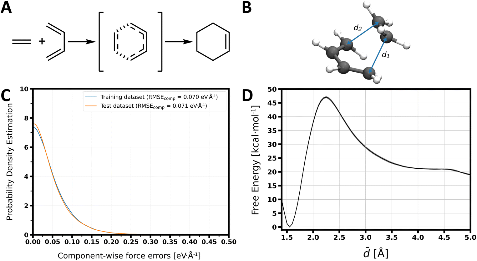 | ||
Fig. 7 (A) Mechanism of the Diels–Alder reaction between ethene and s-cis-1,3-butadiene. (B) Key collective variables used to describe the reaction: the distances d1 and d2 (C) Probability density of the component-wise force errors in the training and test datasets. (D) Free energy profile along the average ![[d with combining macron]](https://www.rsc.org/images/entities/i_char_0064_0304.gif) of the d1 and d2 distances obtained from US simulations with the NNP trained on the R8 dataset, with the average value (solid colors) and the 95% confidence interval (shaded colors). of the d1 and d2 distances obtained from US simulations with the NNP trained on the R8 dataset, with the average value (solid colors) and the 95% confidence interval (shaded colors). | ||
The absence of explicit solvent molecules drastically reduces the number of degrees of freedom and hence the training computational complexity. As a consequence, we directly initiated our training with short aiMD simulations sampling the transition between the reactant and product, propagated at the BLYP-D3 DFT level. We performed one simulation in the reactant state (C2H4 + C4H6), with the two molecules kept at close distance, one in the product state (C6H10), and two steered-MD simulations along , respectively from the reactant to the product and from the product to the reactant. From these four trajectories, we generated the aiMD training dataset consisting of 244 structures (61 structures per trajectory) (see Methods and the ESI†).
From this initial dataset, we started the ArcaNN procedure with a mixture of non-reactive and reactive systems based on steered-MD and 1D OPES along the average of the two distances (d1 and d2), corresponding to the newly formed bonds, see Fig. 7B. We performed 8 iterations of the exploration, labeling, and training steps, with a total number of 3519 (244 + 3275) structures in the final dataset, named R8. The training was considered as converged at this point as very few new structures were added to the dataset during the last iteration (<1% of the total number of structures generated during the last exploration).
To assess the quality of the NNPs, we constructed a test dataset of 1095 structures along generated using US simulations with the final R8 NNP (which were primarily used to calculate the reaction free-energy landscape, see Methods). In Fig. 7C, we show the distribution of errors on the force components in the training and test datasets at the final (R8) cycle. The RMSE of the component of the forces is ≃0.07 eV Å−1 on the training dataset and ≃0.07 eV Å−1 on the test set (see Fig. S11†); the RMSE on the forces along the reaction pathway is represented in Fig. S12.†
to calculate the free energy profile of the Diels–Alder reaction (Fig. 7D). The minimum at = 1.5 Å corresponds to the product state (C6H10), the relatively flat region beyond = 4.85 Å corresponds to the reactant state (C4H6 + C2H4), and the maximum at = 2.25 Å corresponds to the transition state. The ΔG and ΔG‡ were calculated from the free energy profile to be −19.0 ± 0.2 kcal mol−1 and 28.1 ± 0.1 kcal mol−1, respectively. This is in fair agreement with the work of Cui and Liu,112 who reported values for ΔG of −14.3 kcal mol−1 and ΔG‡ of 33.2 kcal mol−1 using a static approach at the same level of theory. As per the SN2 reaction, we just report the free energy difference between the different states. We note that our reactant state is not at infinite distance as in the work of Cui and Liu. If we examine the more precisely defined ΔG‡ of the reverse process, i.e,. the ring-opening reaction, we find an excellent agreement between our computed value 47.1 ± 0.2 kcal mol−1 and the previously-published value of 47.5 kcal mol−1.
For this prototypical Diels–Alder reaction, our simulations suggest that the mechanism is concerted and quasi-synchronous, with the two bonds forming at the same time, in agreement with the literature.110,114,115 This can be seen on the probability density distribution of the d1 and d2 distances along the reaction coordinate (see Fig. S13†).
4.3 Methods
The Methods section outlines the generation of initial datasets from aiMD simulations and the subsequent training of NNPs with ArcaNN. It details the non-reactive and reactive iterative training cycles, including dataset augmentation and parameter settings. Finally, it describes the production simulations performed using US (and OPES for the SN2) simulations to explore system reactivity and calculate free energy profiles., with initial σ = 0.05 Å, a deposition pace of 500 timesteps, and ΔE values of 20 kcal mol−1, 50 kcal mol−1, and 70 kcal mol−1, starting from both reactant and product states. In both cases, all ArcaNN parameters were maintained at their default values; 3 NNPs were trained for the committee with 2 trajectories per NNP used during the exploration step.
![[thin space (1/6-em)]](https://www.rsc.org/images/entities/char_2009.gif) 000 steps. The DeepPot-SE scheme was utilized, setting the cutoff for radial and angular information at 6 Å and applying a cosine weight function for atoms located beyond 0.5 Å. The embedding neural network that maps the environment matrix to a local embedding matrix contains 3 hidden layers with 25, 50, and 100 nodes, respectively. The following fitting neural network that maps the descriptor to the atomic energy contains 3 hidden layers with 240 nodes each. The initial and final energy loss prefactors were set to 0.01 and 1, respectively, and the force loss prefactors were set to 1000 and 1, respectively.
000 steps, and a print interval of 200 MD steps (i.e., 1% of the total length). The simulations were conducted in the NVT ensemble at 300 K with a CSVR thermostat116 and a time constant of 0.1 ps. The maximum deviation on the atomic forces was set to 0.15 for σlow, 0.7 for σhigh, and 1.0 eV Å−1 for σmax as the candidate selection criteria. At the seventh iteration, only 5 candidates were selected from the 36 MD simulations (three NNPs, two per NNP, and six systems), each lasting 400 ps. Therefore, it was decided to restart the ArcaNN procedure with a biased exploration to include reactive structures. The total number of configurations in the training dataset at this point was 1158, which will be referred to as the NR7 training dataset.
000 steps, and a print interval of 200 MD steps (i.e., 1% of the total length), at 300 K with a CSVR thermostat116 and a time constant of 0.1 ps−1. After 8 iterations of the ArcaNN procedure, the final dataset contained 3519 configurations, referred to as the R8 training dataset.
000 steps. The DeepPot-SE scheme was utilized, setting the cutoff for radial and angular information at 6 Å and applying a cosine weight function for atoms located beyond 0.5 Å. The embedding neural network that maps the environment matrix to a local embedding matrix contains 3 hidden layers with 25, 50, and 100 nodes, respectively. The following fitting neural network that maps the descriptor to the atomic energy contains 3 hidden layers with 240 nodes each. The initial and final energy loss prefactors were set to 0.01 and 1, respectively, and the force loss prefactors were set to 1000 and 1, respectively.
000 steps, and a print interval of 200 MD steps (i.e., 1% of the total length). The simulations were conducted in the NVT ensemble at 300 K with a CSVR thermostat116 and a time constant of 0.1 ps. The maximum deviation on the atomic forces was set to 0.15 for σlow, 0.7 for σhigh, and 1.0 eV Å−1 for σmax as the candidate selection criteria. At the seventh iteration, only 5 candidates were selected from the 36 MD simulations (three NNPs, two per NNP, and six systems), each lasting 400 ps. Therefore, it was decided to restart the ArcaNN procedure with a biased exploration to include reactive structures. The total number of configurations in the training dataset at this point was 1158, which will be referred to as the NR7 training dataset.
000 steps, and a print interval of 200 MD steps (i.e., 1% of the total length), at 300 K with a CSVR thermostat116 and a time constant of 0.1 ps−1. After 8 iterations of the ArcaNN procedure, the final dataset contained 3519 configurations, referred to as the R8 training dataset.
The 600 ps long production runs were divided into 6 blocks of 100 ps each, and the 1D free energy profile was calculated for each block using the Weighted Histogram Analysis Method (WHAM)117 with 312 bins along δd. Then using each block result, the average and the 95% confidence interval were calculated by setting the free energy at 0 kcal mol−1 at δd = −1.95. The ΔG and ΔG‡ were calculated from the averaged 1D free energy profile as the difference between the free energy of the reactant (CH3Cl + Br−) and product states (CH3Br + Cl−) and the difference between the free energy of the reactant and the maximum (the transition state) of the free energy profile, respectively. For the collective variables, each structure for all windows (and the full duration) was binned to a grid of δd values (same binning as the WHAM procedure), and the average and 95% confidence interval were calculated for each bin for the dC–Cl distance, the dC–Br distance, and the ω angle.
For the OPES simulations with the final R5 NNP, bias was applied to the dC–Br and dC–Cl distances, with σ = 0.05 Å for both, a deposition pace of 500 timesteps, and ΔE equal to 20 kcal mol−1. The simulation was propagated for 2.5 ns in the NVT ensemble at 300 K with a timestep of 0.5 fs using a CSVR thermostat116 with a time constant of 0.1 ps−1 (same as the production US simulations). The 2D free energy surface was calculated by reweighting the biased simulations along the dC–Br and dC–Cl distances (Fig. 5). The simulations were divided into 5 blocks of 500 ps each, and the free energy was calculated for each block by reweighting along the δd collective variables, permitting the calculation of an average and 95% interval 1D free energy profile (see Fig. S15†). The ΔG and ΔG‡ were calculated as described above for the US simulations. The same procedure as the US simulations was used to calculate the average and 95% confidence interval for the dC–Cl distance, the dC–Br distance, and the ω angle.
(see Fig. 7B). The reaction was divided into 73 windows, linearly spaced from = 1.4 Å to = 5.0 Å. All subsequent simulations were performed in the NVT ensemble at 300 K with a timestep of 0.5 fs, using a CSVR thermostat116 with a time constant of 0.1 ps−1. To maintain the system in the s-cis conformation, a flat-bottom restraint was applied to the dihedral angle with a force constant of 100 kcal mol−1 rad−2 to keep it between –π/2 rad and π/2 rad. For each window, the system was equilibrated by performing steered-MD to the target value over 50 ps with a spring constant of 1000 kcal mol−1 Å−2. This was followed by an additional 50 ps equilibration at the target value, and production runs of 600 ps for each window. The total simulation time accrued was 42.6 ns, with a simulation speed of approximately 24 ns per day on a single GPU. The free energy profile, along with its average and 95% confidence interval, as well as the ΔG and ΔG‡ values, was calculated using the same procedure as for the SN2 reaction.
, and labeling them at the reference level of theory.
5 Conclusion
ArcaNN addresses the challenge of generating training datasets for reactive MLIPs. By combining concurrent learning with advanced sampling techniques, ArcaNN facilitates the exploration of chemically relevant configurations, including high-energy geometries, and integrates classical and quantum nuclear dynamics into a standardized automated workflow. The framework is designed to be user-friendly and flexible, allowing researchers to easily set up and run ArcaNN to train neural network potentials (NNPs) for their reactive systems. We illustrated the power of ArcaNN in the context of two different reactions: first, a nucleophilic substitution (SN2) reaction in explicit solvent, and second, a pericyclic reaction in the gas phase. In both cases, we demonstrated its capabilities in generating accurate and stable NNPs, both in the reactant and product region, but most importantly along the reaction pathway. Beyond these simple examples, preliminary versions of the code were used by us for much more complex reactions involving several molecular steps and multiple pathways.14,15 We also note that the training set obtained for these reactions can be used as a starting point to study similar but more complex reactions presenting different nucleophiles and leaving groups for the SN2, or functionalized dienes and dienophiles for the Diels–Alder reaction, respectively. Although an initial aiMD training set is still needed to ensure a stable initial representation of the functionalized reagents (especially in the presence of new chemical elements), the reactive configurations in the present dataset will significantly accelerate the iterative procedure needed to refine the description of related systems exhibiting similar reactivity. We also provide guidelines on how to assess the quality of a NNP for a reactive system, suggesting that many aspects should be considered beyond the canonical RMSE on the energies and forces. Future developments of ArcaNN will include the incorporation of additional selection techniques, expansion to use other MLIPs, integration with different molecular dynamics engines, and support for various quantum chemistry packages for labeling.Through continuous improvements, ArcaNN aims to facilitate the broader adoption and application of MLIPs in computational chemistry, enabling new advancements in chemical reactivity and catalysis.
Data availability
The code for ArcaNN can be found at https://github.com/arcann-chem/arcann_training. An in-depth documentation is available at https://arcann-chem.github.io/arcann_training. The version of the code employed for this study is version 1. Necessary user files and initial aiMD datasets to start the training of the NNPs for the SN2 and the Diels–Alder reaction with ArcaNN are available in the Examples section of the GitHub repository: https://github.com/arcann-chem/arcann_training.Author contributions
Rolf David: conceptualization, methodology, software, supervision, validation, formal analysis, investigation, visualization, writing-original draft, writing-review and editing. Miguel de la Puente: software, validation, resources, writing-review and editing. Axel Gomez: software, validation, resources, writing-review and editing. Olaia Anton: validation, resources, writing-original draft, writing-review and editing. Guillaume Stirnemann: conceptualization, funding acquisition, project administration, supervision, writing-original draft, writing-review and editing. Damien Laage: conceptualization, funding acquisition, project administration, supervision, writing-original draft, writing-review and editing.Conflicts of interest
There are no conflicts to declare.Acknowledgements
This work was supported by a postdoctoral fellowship to R. D. from PSL OCAV (Idex ANR-10-IDEX-0001-02PSL) and from the European Research Council (ERC) under the European Union's Eighth Framework Program (H2020/2014–2020)/ERC grant agreement no. 757111. This project was provided with HPC and storage resources by GENCI at IDRIS/TGCC, thanks to grants A0110707156, A0130707156, A0150707156, A0130811005, and A0150811005, on the Jean Zay and Joliot Curie supercomputers, specifically on the ROME, CSL, V100, and A100 partitions. The authors thank the ENS group members and collaborators who have tested the preliminary versions of the code: Zakarya Benayad, Pierre Vieillard, Oscar Gayraud, Pierre Girard, Anne Milet, Meritxell Malagarriga Pérez, Adrián García-Martínez, Ashley Borkowski, Pauf Neupane, Ward H. Thompson, Mohammadhasan Dinpajooh, and Tomonori Hirano.Notes and references
- D. Lu, H. Wang, M. Chen, L. Lin, R. Car, W. E, W. Jia and L. Zhang, Comput. Phys. Commun., 2021, 259, 107624 CrossRef CAS.
- L. Zhang, H. Wang, R. Car and W. E, Phys. Rev. Lett., 2021, 126, 236001 CrossRef CAS PubMed.
- P. M. Piaggi, A. Z. Panagiotopoulos, P. G. Debenedetti and R. Car, J. Chem. Theory Comput., 2021, 17, 3065–3077 CrossRef CAS.
- R. He, H. Wu, L. Zhang, X. Wang, F. Fu, S. Liu and Z. Zhong, Phys. Rev. B, 2022, 105, 064104 CrossRef CAS.
- R. Ryltsev and N. Chtchelkatchev, J. Mol. Liq., 2022, 349, 118181 CrossRef CAS.
- M. de la Puente, R. David, A. Gomez and D. Laage, J. Am. Chem. Soc., 2022, 144, 10524–10529 CrossRef CAS.
- B. Wen, M. F. C. Andrade, L.-M. Liu and A. Selloni, Proc. Natl. Acad. Sci. U. S. A., 2023, 120, e2212250120 CrossRef CAS.
- M. de la Puente, A. Gomez and D. Laage, J. Phys. Chem. Lett., 2024, 15, 3096–3102 CrossRef CAS PubMed.
- G. Azom, A. Milet, R. David and R. Kumar, J. Phys. Chem. C, 2024, 128(39), 16437–16453, DOI:10.1021/acs.jpcc.4c03444.
- O. T. Unke, M. Stöhr, S. Ganscha, T. Unterthiner, H. Maennel, S. Kashubin, D. Ahlin, M. Gastegger, L. M. Sandonas, J. T. Berryman, A. Tkatchenko and K.-R. Müller, Sci. Adv., 2024, 10, eadn4397 CrossRef CAS PubMed.
- J. Zeng, L. Zhang, H. Wang and T. Zhu, Energy Fuels, 2021, 35, 762–769 CrossRef CAS.
- T. A. Young, T. Johnston-Wood, H. Zhang and F. Duarte, Phys. Chem. Chem. Phys., 2022, 24, 20820–20827 RSC.
- T. Devergne, T. Magrino, F. Pietrucci and A. M. Saitta, J. Chem. Theory Comput., 2022, 18, 5410–5421 CrossRef CAS PubMed.
- Z. Benayad, R. David and G. Stirnemann, Proc. Natl. Acad. Sci. U. S. A., 2024, 121, e2322040121 CrossRef CAS PubMed.
- R. David, I. Tuñón and D. Laage, J. Am. Chem. Soc., 2024, 146, 14213–14224 CrossRef CAS PubMed.
- A. Gomez, W. H. Thompson and D. Laage, Nat. Chem., 2024, 16, 1838–1844, DOI:10.1038/s41557-024-01593-y.
- A. Mondal, D. Kussainova, S. Yue and A. Z. Panagiotopoulos, J. Chem. Theory Comput., 2023, 19, 4584–4595 CrossRef CAS.
- S. K. Achar, L. Bernasconi, R. I. DeMaio, K. R. Howard and J. K. Johnson, ACS Appl. Mater. Interfaces, 2023, 15, 25873–25883 CrossRef CAS.
- Z. Zeng, F. Wodaczek, K. Liu, F. Stein, J. Hutter, J. Chen and B. Cheng, Nat. Commun., 2023, 14, 6131 CrossRef CAS.
- P. Zhang, A. T. Gardini, X. Xu and M. Parrinello, J. Chem. Inf. Model., 2024, 64, 3599–3604 CrossRef CAS PubMed.
- A. P. Bartók, S. De, C. Poelking, N. Bernstein, J. R. Kermode, G. Csányi and M. Ceriotti, Sci. Adv., 2017, 3, e1701816 CrossRef.
- S. Chmiela, H. E. Sauceda, K.-R. Müller and A. Tkatchenko, Nat. Commun., 2018, 9, 3887 CrossRef.
- C. Schran, F. L. Thiemann, P. Rowe, E. A. Müller, O. Marsalek and A. Michaelides, Proc. Natl. Acad. Sci. U. S. A., 2021, 118, e2110077118 CrossRef CAS PubMed.
- J. A. Keith, V. Vassilev-Galindo, B. Cheng, S. Chmiela, M. Gastegger, K.-R. Müller and A. Tkatchenko, Chem. Rev., 2021, 121, 9816–9872 CrossRef CAS PubMed.
- O. T. Unke, S. Chmiela, H. E. Sauceda, M. Gastegger, I. Poltavsky, K. T. Schütt, A. Tkatchenko and K.-R. Müller, Chem. Rev., 2021, 121, 10142–10186 CrossRef CAS.
- Y. Ding, B. Qiang, Q. Chen, Y. Liu, L. Zhang and Z. Liu, J. Chem. Inf. Model., 2024, 64, 2955–2970 CrossRef CAS.
- K.-R. Muller, S. Mika, G. Ratsch, K. Tsuda and B. Scholkopf, IEEE Trans. Neural Network., 2001, 12, 181–201 CrossRef CAS.
- A. P. Bartók, M. C. Payne, R. Kondor and G. Csányi, Phys. Rev. Lett., 2010, 104, 136403 CrossRef PubMed.
- S. Käser, L. I. Vazquez-Salazar, M. Meuwly and K. Töpfer, Digital Discovery, 2023, 2, 28–58 RSC.
- J. Behler and M. Parrinello, Phys. Rev. Lett., 2007, 98, 146401 CrossRef PubMed.
- J. Behler, J. Chem. Phys., 2011, 134, 074106 CrossRef.
- J. Behler, J. Phys.: Condens. Matter, 2014, 26, 183001 CrossRef CAS.
- J. Behler, Chem. Rev., 2021, 121, 10037–10072 CrossRef CAS PubMed.
- J. S. Smith, O. Isayev and A. E. Roitberg, Chem. Sci., 2017, 8, 3192–3203 RSC.
- C. Devereux, J. S. Smith, K. K. Huddleston, K. Barros, R. Zubatyuk, O. Isayev and A. E. Roitberg, J. Chem. Theory Comput., 2020, 16, 4192–4202 CrossRef CAS.
- L. Zhang, J. Han, H. Wang, R. Car and W. E, Phys. Rev. Lett., 2018, 120, 143001 CrossRef CAS.
- L. Zhang, J. Han, H. Wang, W. Saidi, R. Car and W. E, Adv. Neural Inf. Process. Syst., 2018, 31 Search PubMed.
- K. T. Schütt, F. Arbabzadah, S. Chmiela, K. R. Müller and A. Tkatchenko, Nat. Commun., 2017, 8, 13890 CrossRef.
- K. Schütt, P.-J. Kindermans, H. E. S. Felix, S. Chmiela, A. Tkatchenko and K.-R. Müller, Adv. Neural Inf. Process. Syst., 2017, 30 Search PubMed.
- O. T. Unke and M. Meuwly, J. Chem. Theory Comput., 2019, 15, 3678–3693 CrossRef CAS.
- N. Lubbers, J. S. Smith and K. Barros, J. Chem. Phys., 2018, 148, 241715 CrossRef PubMed.
- S. Batzner, A. Musaelian, L. Sun, M. Geiger, J. P. Mailoa, M. Kornbluth, N. Molinari, T. E. Smidt and B. Kozinsky, Nat. Commun., 2022, 13, 2453 CrossRef CAS PubMed.
- A. Musaelian, S. Batzner, A. Johansson, L. Sun, C. J. Owen, M. Kornbluth and B. Kozinsky, Nat. Commun., 2023, 14, 579 CrossRef CAS PubMed.
- T. W. Ko, J. A. Finkler, S. Goedecker and J. Behler, Nat. Commun., 2021, 12, 398 CrossRef CAS PubMed.
- L. Zhang, H. Wang, M. C. Muniz, A. Z. Panagiotopoulos, R. Car and W. E, J. Chem. Phys., 2022, 156, 124107 CrossRef CAS PubMed.
- T. W. Ko, J. A. Finkler, S. Goedecker and J. Behler, J. Chem. Theory Comput., 2023, 19, 3567–3579 CrossRef CAS.
- M. E. Tuckerman, J. Phys.: Condens. Matter, 2002, 14, R1297–R1355 CrossRef CAS.
- D. Marx and J. Hutter, Ab Initio Molecular Dynamics: Basic Theory and Advanced Methods, Cambridge University Press, 1st edn, 2009 Search PubMed.
- T. P. Senftle, S. Hong, M. M. Islam, S. B. Kylasa, Y. Zheng, Y. K. Shin, C. Junkermeier, R. Engel-Herbert, M. J. Janik, H. M. Aktulga, T. Verstraelen, A. Grama and A. C. T. Van Duin, npj Comput. Mater., 2016, 2, 15011 CrossRef CAS.
- I. Batatia, P. Benner, Y. Chiang, A. M. Elena, D. P. Kovács, J. Riebesell, X. R. Advincula, M. Asta, M. Avaylon, W. J. Baldwin, F. Berger, N. Bernstein, A. Bhowmik, S. M. Blau, V. Cărare, J. P. Darby, S. De, F. Della Pia, V. L. Deringer, R. Elijošius, Z. El-Machachi, F. Falcioni, E. Fako, A. C. Ferrari, A. Genreith-Schriever, J. George, R. E. A. Goodall, C. P. Grey, P. Grigorev, S. Han, W. Handley, H. H. Heenen, K. Hermansson, C. Holm, J. Jaafar, S. Hofmann, K. S. Jakob, H. Jung, V. Kapil, A. D. Kaplan, N. Karimitari, J. R. Kermode, N. Kroupa, J. Kullgren, M. C. Kuner, D. Kuryla, G. Liepuoniute, J. T. Margraf, I.-B. Magdău, A. Michaelides, J. H. Moore, A. A. Naik, S. P. Niblett, S. W. Norwood, N. O'Neill, C. Ortner, K. A. Persson, K. Reuter, A. S. Rosen, L. L. Schaaf, C. Schran, B. X. Shi, E. Sivonxay, T. K. Stenczel, V. Svahn, C. Sutton, T. D. Swinburne, J. Tilly, C. van der Oord, E. Varga-Umbrich, T. Vegge, M. Vondrák, Y. Wang, W. C. Witt, F. Zills and G. Csányi, arXiv, 2024, preprint, arXiv:2401.00096, https://doi.org/10.48550/arXiv.2401.00096 Search PubMed.
- L. Zhang, D.-Y. Lin, H. Wang, R. Car and W. E, Phys. Rev. Mater., 2019, 3, 023804 CrossRef CAS.
- H. S. Seung, M. Opper and H. Sompolinsky, Proceedings of the Fifth Annual Workshop on Computational Learning Theory, Pittsburgh Pennsylvania USA, 1992, pp. 287–294 Search PubMed.
- Y. Zhang, H. Wang, W. Chen, J. Zeng, L. Zhang, H. Wang and W. E, Comput. Phys. Commun., 2020, 253, 107206 CrossRef CAS.
- Y.-X. Guo, Y.-B. Zhuang, J. Shi and J. Cheng, J. Chem. Phys., 2023, 159, 094801 CrossRef CAS PubMed.
- D. Schwalbe-Koda, A. R. Tan and R. Gómez-Bombarelli, Nat. Commun., 2021, 12, 5104 CrossRef CAS PubMed.
- Y. Xie, J. Vandermause, S. Ramakers, N. H. Protik, A. Johansson and B. Kozinsky, npj Comput. Mater., 2023, 9, 36 CrossRef CAS.
- M. Kulichenko, K. Barros, N. Lubbers, Y. W. Li, R. Messerly, S. Tretiak, J. S. Smith and B. Nebgen, Nat. Comput. Sci., 2023, 3, 230–239 CrossRef PubMed.
- C. Van Der Oord, M. Sachs, D. P. Kovács, C. Ortner and G. Csányi, npj Comput. Mater., 2023, 9, 168 CrossRef CAS.
- V. Zaverkin, D. Holzmüller, H. Christiansen, F. Errica, F. Alesiani, M. Takamoto, M. Niepert and J. Kästner, npj Comput. Mater., 2024, 10, 83 CrossRef.
- D. Anstine, R. Zubatyuk and O. Isayev, ChemRxiv, 2024, preprint, DOI:10.26434/chemrxiv-2023-296ch-v2.
- Y. Yang, S. Zhang, K. D. Ranasinghe, O. Isayev and A. E. Roitberg, Annu. Rev. Phys. Chem., 2024, 75, 371–395 CrossRef CAS.
- S. Zhang, M. Z. Makoś, R. B. Jadrich, E. Kraka, K. Barros, B. T. Nebgen, S. Tretiak, O. Isayev, N. Lubbers, R. A. Messerly and J. S. Smith, Nat. Chem., 2024, 16, 727–734 CrossRef CAS.
- M. Schreiner, A. Bhowmik, T. Vegge, J. Busk and O. Winther, Sci. Data, 2022, 9, 779 CrossRef PubMed.
- M. Yang, L. Bonati, D. Polino and M. Parrinello, Catal. Today, 2022, 387, 143–149 CrossRef CAS.
- T. A. Young, T. Johnston-Wood, V. L. Deringer and F. Duarte, Chem. Sci., 2021, 12, 10944–10955 RSC.
- K. Brezina, H. Beck and O. Marsalek, J. Chem. Theory Comput., 2023, 19, 6589–6604 CrossRef CAS.
- S. Perego and L. Bonati, ChemRxiv, 2024, preprint, DOI:10.26434/chemrxiv-2024-nsp7n.
- M. Pinheiro, F. Ge, N. Ferré, P. O. Dral and M. Barbatti, Chem. Sci., 2021, 12, 14396–14413 RSC.
- M. Uhrin, Phys. Rev. B, 2021, 104, 144110 CrossRef CAS.
- S. Raghunathan and U. D. Priyakumar, Int. J. Quantum Chem., 2022, 122, e26870 CrossRef CAS.
- H. Gokcan and O. Isayev, Wiley Interdiscip. Rev.: Comput. Mol. Sci., 2022, 12, e1564 Search PubMed.
- J. Lin, R. Tamura, Y. Futamura, T. Sakurai and T. Miyazaki, Phys. Chem. Chem. Phys., 2023, 25, 17978–17986 RSC.
- A. M. Tokita and J. Behler, J. Chem. Phys., 2023, 159, 121501 CrossRef CAS.
- A. Gomez, M. de la Puente, R. David and D. Laage, C. R. Chim., 2024, 27, 1–17 CrossRef CAS.
- J. Gilmer, S. S. Schoenholz, P. F. Riley, O. Vinyals and G. E. Dahl, Proceedings of the 34th International Conference on Machine Learning, 2017, vol. 70, pp. 1263–1272 Search PubMed.
- D. M. Anstine and O. Isayev, J. Phys. Chem. A, 2023, 127, 2417–2431 CrossRef CAS.
- S. Chmiela, V. Vassilev-Galindo, O. T. Unke, A. Kabylda, H. E. Sauceda, A. Tkatchenko and K.-R. Müller, Sci. Adv., 2023, 9, eadf0873 CrossRef.
- B. Settles, Active Learning, Springer International Publishing, Cham, 2012 Search PubMed.
- G. Torrie and J. Valleau, J. Comput. Phys., 1977, 23, 187–199 CrossRef.
- A. Laio and M. Parrinello, Proc. Natl. Acad. Sci. U. S. A., 2002, 99, 12562–12566 CrossRef CAS.
- A. Barducci, G. Bussi and M. Parrinello, Phys. Rev. Lett., 2008, 100, 020603 CrossRef PubMed.
- M. Invernizzi and M. Parrinello, J. Phys. Chem. Lett., 2020, 11, 2731–2736 CrossRef CAS.
- M. de la Puente and D. Laage, J. Am. Chem. Soc., 2023, 145, 25186–25194 CrossRef CAS PubMed.
- M. D. Wilkinson, M. Dumontier, I. J. Aalbersberg, G. Appleton, M. Axton, A. Baak, N. Blomberg, J.-W. Boiten, L. Bonino da Silva Santos, P. E. Bourne, J. Bouwman, A. J. Brookes, T. Clark, M. Crosas, I. Dillo, O. Dumon, S. Edmunds, C. T. Evelo, R. Finkers, A. Gonzalez-Beltran, A. J. G. Gray, P. Groth, C. Goble, J. S. Grethe, J. Heringa, P. A. C. ’t Hoen, R. Hooft, T. Kuhn, R. Kok, J. Kok, S. J. Lusher, M. E. Martone, A. Mons, A. L. Packer, B. Persson, P. Rocca-Serra, M. Roos, R. van Schaik, S.-A. Sansone, E. Schultes, T. Sengstag, T. Slater, G. Strawn, M. A. Swertz, M. Thompson, J. van der Lei, E. van Mulligen, J. Velterop, A. Waagmeester, P. Wittenburg, K. Wolstencroft, J. Zhao and B. Mons, Sci. Data, 2016, 3, 160018 CrossRef.
- T. D. Kühne, M. Iannuzzi, M. Del Ben, V. V. Rybkin, P. Seewald, F. Stein, T. Laino, R. Z. Khaliullin, O. Schütt, F. Schiffmann, D. Golze, J. Wilhelm, S. Chulkov, M. H. Bani-Hashemian, V. Weber, U. Borštnik, M. Taillefumier, A. S. Jakobovits, A. Lazzaro, H. Pabst, T. Müller, R. Schade, M. Guidon, S. Andermatt, N. Holmberg, G. K. Schenter, A. Hehn, A. Bussy, F. Belleflamme, G. Tabacchi, A. Glöβ, M. Lass, I. Bethune, C. J. Mundy, C. Plessl, M. Watkins, J. V. Vondele, M. Krack and J. Hutter, J. Chem. Phys., 2020, 152, 194103 CrossRef.
- H. Wang, L. Zhang, J. Han and W. E, Comput. Phys. Commun., 2018, 228, 178–184 CrossRef CAS.
- J. Zeng, D. Zhang, D. Lu, P. Mo, Z. Li, Y. Chen, M. Rynik, L. Huang, Z. Li, S. Shi, Y. Wang, H. Ye, P. Tuo, J. Yang, Y. Ding, Y. Li, D. Tisi, Q. Zeng, H. Bao, Y. Xia, J. Huang, K. Muraoka, Y. Wang, J. Chang, F. Yuan, S. L. Bore, C. Cai, Y. Lin, B. Wang, J. Xu, J.-X. Zhu, C. Luo, Y. Zhang, R. E. A. Goodall, W. Liang, A. K. Singh, S. Yao, J. Zhang, R. Wentzcovitch, J. Han, J. Liu, W. Jia, D. M. York, W. E, R. Car, L. Zhang and H. Wang, J. Chem. Phys., 2023, 159, 054801 CrossRef CAS PubMed.
- A. P. Thompson, H. M. Aktulga, R. Berger, D. S. Bolintineanu, W. M. Brown, P. S. Crozier, P. J. in ’t Veld, A. Kohlmeyer, S. G. Moore, T. D. Nguyen, R. Shan, M. J. Stevens, J. Tranchida, C. Trott and S. J. Plimpton, Comput. Phys. Commun., 2022, 271, 108171 CrossRef CAS.
- V. Kapil, M. Rossi, O. Marsalek, R. Petraglia, Y. Litman, T. Spura, B. Cheng, A. Cuzzocrea, R. H. Meißner, D. M. Wilkins, B. A. Helfrecht, P. Juda, S. P. Bienvenue, W. Fang, J. Kessler, I. Poltavsky, S. Vandenbrande, J. Wieme, C. Corminboeuf, T. D. Kühne, D. E. Manolopoulos, T. E. Markland, J. O. Richardson, A. Tkatchenko, G. A. Tribello, V. Van Speybroeck and M. Ceriotti, Comput. Phys. Commun., 2019, 236, 214–223 CrossRef CAS.
- G. A. Tribello, M. Bonomi, D. Branduardi, C. Camilloni and G. Bussi, Comput. Phys. Commun., 2014, 185, 604–613 CrossRef CAS.
- W. Humphrey, A. Dalke and K. Schulten, J. Mol. Graphics, 1996, 14, 33–38 CrossRef CAS PubMed.
- P. Hirel, Comput. Phys. Commun., 2015, 197, 212–219 CrossRef CAS.
- R. David, M. de la Puente, A. Gomez, O. Anton, G. Stirnemann and D. Laage, ArcaNN, GitHub, 2024 Search PubMed.
- H. Grubmüller, B. Heymann and P. Tavan, Science, 1996, 271, 997–999 CrossRef PubMed.
- M. Elstner, D. Porezag, G. Jungnickel, J. Elsner, M. Haugk, T. Frauenheim, S. Suhai and G. Seifert, Phys. Rev. B: Condens. Matter Mater. Phys., 1998, 58, 7260–7268 CrossRef CAS.
- M. Elstner and G. Seifert, Philos. Trans. R. Soc., A, 2014, 372, 20120483 CrossRef.
- C. Bannwarth, S. Ehlert and S. Grimme, J. Chem. Theory Comput., 2019, 15, 1652–1671 CrossRef CAS PubMed.
- D. Lu, W. Jiang, Y. Chen, L. Zhang, W. Jia, H. Wang and M. Chen, J. Chem. Theory Comput., 2022, 18, 5559–5567 CrossRef CAS.
- J. Chandrasekhar, S. F. Smith and W. L. Jorgensen, J. Am. Chem. Soc., 1984, 106, 3049–3050 CrossRef CAS.
- J. Chandrasekhar, S. F. Smith and W. L. Jorgensen, J. Am. Chem. Soc., 1985, 107, 154–163 CrossRef CAS.
- J. P. Bergsma, B. J. Gertner, K. R. Wilson and J. T. Hynes, J. Chem. Phys., 1987, 86, 1356–1376 CrossRef CAS.
- J.-K. Hwang, G. King, S. Creighton and A. Warshel, J. Am. Chem. Soc., 1988, 110, 5297–5311 CrossRef CAS.
- S. Raugei, G. Cardini and V. Schettino, J. Chem. Phys., 1999, 111, 10887–10894 CrossRef CAS.
- S. Raugei, G. Cardini and V. Schettino, J. Chem. Phys., 2001, 114, 4089–4098 CrossRef CAS.
- M. Pagliai, S. Raugei, G. Cardini and V. Schettino, J. Mol. Struct.: THEOCHEM, 2003, 630, 141–149 CrossRef CAS.
- D. Valverde, H. C. Georg and S. Canuto, J. Phys. Chem. B, 2022, 126, 3685–3692 CrossRef CAS PubMed.
- J. D. Morrow, J. L. A. Gardner and V. L. Deringer, J. Chem. Phys., 2023, 158, 121501 CrossRef CAS PubMed.
- T. Maxson, A. Soyemi, B. W. J. Chen and T. Szilvási, J. Phys. Chem. C, 2024, 128, 6524–6537 CrossRef CAS.
- P. Walden, Ber. Dtsch. Chem. Ges., 1896, 29, 133–138 CrossRef.
- S. Sakai, J. Phys. Chem. A, 2000, 104, 922–927 CrossRef CAS.
- L. R. Domingo and J. A. Sáez, Org. Biomol. Chem., 2009, 7, 3576 RSC.
- C.-X. Cui and Y.-J. Liu, J. Phys. Org. Chem., 2014, 27, 652–660 CrossRef CAS.
- L. R. Pestana, H. Hao and T. Head-Gordon, Nano Lett., 2020, 20, 606–611 CrossRef CAS.
- K. N. Houk, Y. T. Lin and F. K. Brown, J. Am. Chem. Soc., 1986, 108, 554–556 CrossRef CAS.
- D. A. Singleton, B. E. Schulmeier, C. Hang, A. A. Thomas, S.-W. Leung and S. R. Merrigan, Tetrahedron, 2001, 57, 5149–5160 CrossRef CAS.
- G. Bussi, D. Donadio and M. Parrinello, J. Chem. Phys., 2007, 126, 14101 CrossRef.
- S. Kumar, J. M. Rosenberg, D. Bouzida, R. H. Swendsen and P. A. Kollman, J. Comput. Chem., 1992, 13, 1011–1021 CrossRef CAS.
Footnote |
| † Electronic supplementary information (ESI) available: Details of the initial ab initio MD simulations for the SN2 reaction, timings of ArcaNN training for the SN2 and Diels–Alder example reactions, examples of user-provided folder structures, examples of machine JSON files used by ArcaNN, examples of JSON control files generated by ArcaNN, evolution of candidate and rejected structures with exploration time for the ArcaNN reactive training for the SN2 reaction, joint density distribution of key distances in training datasets for the SN2 reaction, validation of the R5 NNP for the SN2 reaction and R8 NNP for the Diels–Alder reaction, free energy profiles and collective variables for NR2 and NR3 NNPs for the SN2 reaction, OPES 1D free energy profiles and CVs from the R5 NNP for the SN2 reaction, and joint density distribution of key distance in the umbrella sampling simulations for the Diels–Alder reaction. See DOI: https://doi.org/10.1039/d4dd00209a |
| This journal is © The Royal Society of Chemistry 2025 |