DOI:
10.1039/D4CS00868E
(Tutorial Review)
Chem. Soc. Rev., 2025,
54, 9145-9160
Virtual transition states: making sense of multiple transition states in parallel and series
Received
5th July 2025
First published on 18th September 2025
Abstract
The apparent Gibbs energies of activation for chemical reactions that involve multiple paths in parallel and/or multiple steps in series may involve several transition states (TSs) lying close in energy. The virtual TS is a weighted average of these contributing real TSs, and the weighting factors are easily obtained from the Gibbs energies of these TSs relative to a common reactant state. Examples from organic reaction mechanisms are used to illustrate the concept and its implications for the interpretation of features of complex Hammett plots and of kinetic isotope effects (KIEs). The concept allows for a considerable simplification of the treatment of KIEs for enzymic reactions, and holds promise for the application of modern methods of computational simulation to assist in the interpretation of experimental kinetic investigations of complex mechanisms.

Ian H. Williams
| Ian Williams is Emeritus Professor of Chemistry at the University of Bath, where he taught physical organic and computational chemistry for many years before retirement in 2021. He continues to pursue research applying computational methods to problems at the interface of physical chemistry and organic chemistry, especially organic reaction mechanisms, enzyme catalysis, and kinetic isotope effects. He is Secretary of the IUPAC Division of Organic and Biomolecular Chemistry during 2026–29, and he chairs the Divisional Project to update terms in this area of chemistry for the IUPAC ‘Gold Book’ Compendium of Chemical Terminology. |
Key learning points
The virtual TS – a weighted average of real TSs – is a useful concept to aid interpretation of empirical observations for complex reaction mechanisms. Multiple TSs in parallel: virtual TS is lower in energy than each individual real TS. Multiple TSs in series: virtual TS is higher in energy than each individual real TS. The traditional treatment of kinetic isotope effects (KIEs) for multistep enzymic reactions is unnecessarily complicated; the “virtual TS” approach is simpler. It is safer and easier to compare computed KIEs directly with observed KIEs and not to ‘intrinsic’ KIEs of dubious validity.
|
1. Interplay of theory and experiment in the elucidation of reaction mechanism
1.1 The role of the transition state
‘The chief value of the transition-state theory in organic chemistry is the picture it gives of how a reaction takes place. Most discussions of the mechanisms of organic reactions are thus presented in terms of the transition-state theory. Indeed, the attempt to find a mechanism of a given reaction is essentially an attempt to define the one or more transition states between the starting materials and the products.’1
This prescient quotation from a 1962 textbook on organic reaction mechanisms (the italics are in the original text) provides the perfect viewpoint from which to start this Tutorial Review, but it differs from what may be seen from inspection of most contemporary textbooks of organic chemistry. More usually, a mechanism for a complex transformation is written as a sequence of intermediates leading from the starting materials to the products, with each step symbolised by a reaction arrow, and often with the formal electron flow within each step being represented by means of curly arrows. There's nothing wrong with that, but it can lead to some unfortunate misunderstandings. In answer to an exam question on the characteristics of SN1 and SN2 mechanisms, this reviewer has many times read (unfortunately) that the former mechanism involves an intermediate while the latter has a transition state (TS); that statement is correct insofar as it goes, but it seems to imply that the SN1 mechanism does not involve a TS whereas, of course, a reaction going by the SN1 mechanism proceeds through (at least) two TSs, one leading to the intermediate and another leading from it. This should be apparent if an energy profile for the reaction is sketched (Fig. 1) between the reactant state (RS) and the product state (PS).
 |
| | Fig. 1 Energy profiles for nucleophilic substitution reactions following (left) SN2 and (right) SN1 mechanisms. | |
Nowadays, browsing the contents of a current issue of any leading journal in the field of chemistry is likely to reveal an account of experimental synthetic and/or mechanistic investigations which are complemented and supported by the results of computational modelling of the reaction sequence, including both intermediates and TSs. This is testament to the very significant advances that have been made over recent decades in the power and accessibility of hardware and software for doing chemistry computationally, as well as to the growing recognition of, and appreciation for, the complementary roles of theory and experiment. While chemistry is (and always will be) an empirical subject, its development depends (and always has done) on models, concepts, and theories. The relationship between theory and experiment in the characterisation of TSs was explored in an earlier review,2 since when the subject has progressed very considerably.
1.2 Virtual transition states
The quotation above from Waley's textbook contains the crucial phrase ‘one or more transition states’ within the italicised sentence.1 For an elementary reaction there is only one TS, and therefore attempts to infer its nature by means of experimental investigations relate to that single TS alone. However, many reaction mechanisms across the breadth of chemistry and biochemistry (not just organic mechanisms!) involve multiple elementary steps, either in series or in parallel, or a combination of both. It may be the case, within a complex mechanism, that a single TS has a Gibbs energy much higher than those of other relevant TSs and experimental investigations may therefore yield information about this TS in a straightforward manner. But if two or more TSs are encountered between the RS and the PS, and their Gibbs energies do not differ greatly, then experiments provide information not about any individual TS but rather about a weighted average of them. Schowen has denoted this entity as a ‘virtual TS’, and its inferred structure as a ‘virtual transition-state structure’.3
1.3 Transition states and transition structures
At this point it is appropriate to clarify some terminology. The fact that very complex reactions are now studied routinely in condensed media, either in solution, or at an interface, or within the active site of an enzyme, warrants making a distinction between a transition state and a transition structure; both could, of course, be abbreviated as ‘TS’, but it is important to understand that these terms are not synonymous. A transition structure is a molecular entity corresponding to a saddle point on a potential-energy surface, with a specific geometry and energy, and with one negative force constant and its associated imaginary frequency.4 A transition state (for which the acronym TS will be used exclusively in this Tutorial Review) is a state of a molecular system from which there are equal probabilities of evolving toward the reactant state (RS) and product state (PS) of an elementary reaction.4 A transition structure corresponds to the maximum along the minimum-potential-energy path connecting reactant and product structures, but a transition state corresponds to the maximum along the minimum-free-energy path connecting reactant and product states. In the early days of transition-state theory, when the pinnacle of calculational achievement was an approximate potential-energy surface (PES) for H + H2 in vacuum,5 the distinction now being made was unnecessary, even though it was unclear whether the TS was defined by potential energy or free energy.6
1.3.1 Potential energy or free energy?.
The British Nobel laureate, George Porter, at a special meeting of the Chemical Society in 1962 to which the leading experts of the day had been convened to discuss ‘The Transition State’, commented that ‘potential-energy and free-energy are used rather indiscriminately to define the transition state’.7 Contemporary textbooks were equivocal, often labelling the ordinate of an energy profile diagram (cf.Fig. 1) simply as ‘energy’.8,9 Although ‘free energy’10 or, more precisely, ‘standard molar free energy’11 were specified in later books, modern texts still differ in their usage.12,13 While the distinction is of no great significance in many instances (e.g. to describe energy profiles for unimolecular reactions) it is important for other cases (e.g. to explain reactivity effects arising from changes in concentration of a second reagent – see Section 3.1.3). Oancea and de Maeyer have critically considered the merits and demerits of alternative choices of ordinate for free-energy-profile diagrams, including the use of actual concentrations (instead of standard-state concentrations) for some or all components of a reacting system.14
1.3.2 Implications for computational chemistry.
As electronic-structure calculations for organic molecules became increasingly feasible, and the saddle-point on a PES could be located with some precision, so reports of computed ‘transition states’ frequently appeared, even though these should now be considered as transition structures. It is routinely possible to construct an energy-profile diagram for an elementary reaction, with the ordinate as potential energy and the abscissa as some suitable combination of geometrical coordinates that allows for monotonic change from RS to PS via a single TS: intrinsic reaction coordinate (IRC) calculations are commonly used for this purpose.15 More recently it has become possible to perform computational simulations for very large, flexible supramolecular systems16 for which it is impractical to explore comprehensively a complete mega-dimensional potential-energy hypersurface: the appropriate way to determine the energetics of chemical reaction within such a condensed-phase system is evaluate the changes in free energy along a reaction path, often by means of computing the potential of mean force (obtained by averaging over all other coordinates and momenta of the system) with respect to a chosen reaction coordinate.17
A transition structure, defined in relation to a PES, is a mechanical entity (a collection of masses, connected by springs, with a definite average geometry); but a transition state, defined in relation to a free-energy surface (FES), is a statistical-mechanical entity.6,18 It is now common to compute the standard molar enthalpy and entropy of a transition structure within the rigid-rotor harmonic-oscillator ideal-gas approximation19 (usually at a standard pressure of 1 atm and a temperature of 298.15 K) and to present its energy relative to a reactant structure as a Gibbs energy of activation. It should be noted that this method assumes that a single (microscopic) structure is entirely representative of the myriad (e.g. Avogadro's number) of structures in a macroscopic system at a given temperature and pressure. Similarly, if solvation energies are estimated by means of a continuum model,20 the resulting free energies (usually for a standard state of 1 M) are obtained in an implicitly averaged manner (by virtue of the parameterisation within the model), so that a single structure stands in for an entire ensemble of structures. Such approximations are useful, but not always wholly correct. It was pointed out long ago that the position of the maximum along a minimum-energy path across a PES often does not coincide with the position of the maximum along a minimum-energy path across a FES;18 variational transition-state theory takes this into account by seeking to find the true free-energy bottleneck to a reaction.6,21
1.4 Transition-state structure
Having carefully distinguished the terms transition structure and transition state, what should one call a structure (usually rather approximate) that is inferred for the TS of a chemical reaction by means of the application of (usually indirect) experimental techniques? For example, the value of the reaction parameter ρ from a Hammett correlation may be interpreted as a measure of charge development at the reacting centre in a transition state,2,22 or a kinetic isotope effect (KIE) may be interpreted as a measure of bonding change or hybridisation as between the RS and the TS.2,22 The term ‘transition-state structure’ serves this purpose. Many examples may be found in the literature of organic and bio-organic chemistry.23,24 For example, linear free-energy relationships have been used to deduce features of transition-state structure in biological phosphoryl-transfer reactions25 and KIEs for multiple isotopic substitutions have been extensively employed to derive transition-state structures for a wide range of enzymic reactions.26 Of course, if the reaction under investigation has a complex mechanism involving multiple TSs in parallel or in series, then experiments yield information about a virtual TS structure, as noted above.3 Stein has described this situation succinctly as follows.
‘For reactions in which more than a single TS is kinetically significant, any experiment designed to probe the structure of the rate-limiting TS will yield information not about a single, real TS, but rather about a “virtual” TS whose structure is a weighted average of structures of the several rate-limiting, real TSs.’24
2. Multiple TSs in parallel
2.1 Multiple paths from a single RS
Consider the possibility that a single RS leads to a single PS by means of multiple pathways in parallel. Each pathway across the PES for the reacting system has a distinct saddle point and the FES in that vicinity has a TS at the maximum along each separate path of minimum free energy. The situation is illustrated by Fig. 2 which shows five paths in parallel, each with its own TS.
 |
| | Fig. 2 Multiple paths in parallel from a single RS. Each TS is located at a minimum along the left-right ridge of the ‘sierra’, but each is located at the highest point through its own mountain pass from front (RS) to back (PS). | |
The total rate of reaction from RS to PS is the sum of the rates for reaction by each of the separate paths, and the observed (or empirical) rate constant is the apparent rate constant kparallelapp given by the sum of the individual rate constants ki (eqn (1)). Generalising for N parallel pathways, the apparent Gibbs energy of activation Δ‡Gparallelapp is given by eqn (2).
| |  | (1) |
| |  | (2) |
This apparent Gibbs energy of activation corresponds to the virtual TS for this complex reaction mechanism. The contribution of each individual TSi to the overall activation energy is simply its Boltzmann weighting, wi, as given by eqn (3).
| |  | (3) |
Corresponding with normal chemical intuition, the TS that makes the largest contribution is the one with the lowest Gibbs energy. Moreover, it is important to note that the apparent Gibbs energy of activation is less than any of the values of Δ‡Gi for individual pathways, by virtue of entropy (see below).
2.1.1 Enantiomeric TSs.
A trivial example of parallel pathways from a single RS would be any reaction involving achiral reactants that proceeds via a pair of enantiomeric TSs. Clearly, half of the racemic reaction product is formed by each of the two chiral TSs, with w1 = w2 = 0.5 (from eqn (3)), and the apparent Gibbs energy of activation is lower than the value of Δ‡G1 = Δ‡G2 for the individual TSs by an amount equal to RT![[thin space (1/6-em)]](https://www.rsc.org/images/entities/char_2009.gif) ln2. This difference can be understood as being due the entropy of mixing of the two enantiomeric TSs; equivalently, the virtual TS may be considered to have a symmetry number equal to ½.28
ln2. This difference can be understood as being due the entropy of mixing of the two enantiomeric TSs; equivalently, the virtual TS may be considered to have a symmetry number equal to ½.28
2.1.2 Complex Hammett plot for stilbene bromination.
A Hammett plot of logarithms of rate-constant ratios (or of the numerical values of logarithms of rate constants themselves29) against substituent constants σ for a series of reactions involving a set of compounds containing a substituted aryl group may comprise more than a single straight-line section. If, as σ increases positively, the slope (ρ) of the linear correlation changes in a positive direction – for example, from a large negative value of ρ to a less-negative value – then this empirical evidence may indicate a change in reaction mechanism.12,30,31 The electrophilic bromination of trans-monosubstituted stilbenes illustrates this behaviour (Fig. 3): the initial step is the formal addition of Br+ to the alkene moiety, but this may lead either to an open carbocation (red) or to a cyclic bromonium cation (green) as an intermediate, which is subsequently subjected to nucleophilic attacked by Br− to yield a vicinal dibromide product.
 |
| | Fig. 3 Left: Alternative mechanisms for electrophilic bromination of trans-monosubstituted stilbenes, together with Hammett plot. Strongly electron-donating substituents favour the left-hand path via the open carbocation (red) and are correlated by σ+; electron withdrawing substituents favour the right-hand path via the cyclic bromonium cation (green) and are correlated by σ. Blue points denote X = m-CH3 and H; the solid black curve is represented by eqn (6). Right: Relative Gibbs energies of TSs leading to open (red) and cyclic (green) cationic intermediates for (a) strongly electron-donating substituents, (b) X = m-CH3 and H, (c) electron withdrawing substituents. | |
Second-order rate constants for reaction of stilbenes with Br2 and a large excess of NaBr in methanol at 298 K were reported by Ruasse and Dubois.32 The left-hand side of Fig. 3 shows a Hammett plot of the logarithms of numerical values of the observed rate constants (i.e. reduced second-order rate constants {kobs}29). The compounds with strongly electron-donating substituents give a linear correlation against σ+ (eqn (4) for red points in Fig. 3) with slope ρ = −5.56, whereas electron-withdrawing substituents give a different linear correlation against σ (eqn (5) for green points in Fig. 3) with a much less steep slope ρ = −1.65.
| | | log10{kredobs} = −5.56σ+ + 0.70 | (4) |
| | | log10{kgreenobs} = −1.65σ + 1.29 | (5) |
The change from the ‘red’ to the ‘green’ mechanism reflects the reduction in energy of the latter reaction pathway with respect to the former as the result of the substituents becoming electron-withdrawing instead of electron-attracting: the observed rate constant corresponds to the faster of the two alternative possibilities. However, the values of log10{kobs} for two of the stilbenes (with X = m-CH3 and H, blue) lie above each of the two extrapolated (dotted) linear segments of the plot. These compounds react with larger apparent rate constants than would be predicted from either of the linear correlations: this indicates that they react by both mechanisms in parallel, and that the observed rate constant for each corresponds to a virtual TS. Empirical expressions for kredobs and kgreenobs may be obtained by taking the antilogarithms of eqn (3) and (4); substitution of these into eqn (2) yields an expression for log10{kapp}, eqn (6), which gives the black curve in Fig. 3. The two blue points lie satisfactorily on this curve, as expected;33 moreover, the point of intersection of the extrapolated red and green regression lines occurs at log10{kredobs} = log10{kgreenobs} = 1.54, whereas the value of log10{kblackobs} at this point on the abscissa is 1.84; the difference of 0.3 is equal to log102, as expected for two TSs of equal energy.
| | | log10{kblackapp} = log10[{kredobs} + {kgreenobs}] = log10{10(−5.56σ++0.70) + 10(−1.65σ + 1.29)} | (6) |
In principle, reaction may occur by means of both mechanisms for all substituents, but in practice the contribution of the less-favourable TS is negligible when the mole fraction of one of the competing TSs is less than about 0.01.34 This corresponds to a difference of two log units on the ordinate of the Hammett plot, or to a difference in Gibbs energy between them greater than about RTln(100) ≈ 4.6RT ≈ 11.4 kJ mol−1 at 298 K. The right-hand side of Fig. 3 shows three schematic energy diagrams. The pairs of bold red and green parabolas represent the TSs leading to the open and cyclic cationic intermediates Iopen and Icyclic, respectively, for the two parallel reaction pathways. In (a), the ‘red’ intermediate and TS are significantly lower than the ‘green’ intermediate and TS. As the substituent becomes less electron donating, the energies of all TSs and intermediates are raised relative to reactants R, but more markedly for the ‘red’ species. In (b) the two TSs are of approximately equal energy, whereas in (c) the ‘green’ TS is lower than the ‘red’, even though the barrier heights are greater than in either (a) or (b).
2.2 Multiple RSs and TSs
There are many reactions in which there are multiple RS conformers and multiple TS conformers. If the energetic barriers between the RS conformers were high, then each RS would react separately by means of its own associated TS. However, if the energetic barriers between the RS conformers are low, such that they may interconvert rapidly at the relevant temperature, then Curtin–Hammett conditions apply,35,36 and each RS may undergo reaction by means of any of the TS conformers. Originally, the Curtin–Hammett principle (as first coined by Eliel37) affirmed simply that the ratio of two PSs formed from one RS depends only on the Gibbs-energy difference between the two TSs and is unrelated to the Gibbs energy of the RS. It was soon extended by Winstein and Holness38 (who cited Curtin's personal communication with Hammett, as quoted in a now hard-to-obtain source39) to reactions in which two RS conformers lead to two PSs with relative rates that are independent of the RS Gibbs-energy difference. Their analysis may be further extended to multiple RS conformers and an equal number N of TSs, as in eqn (7), where kii represents the individual rate constant for reaction from RS conformer i (with mole fraction xRSi) through TS conformer i. (Baldwin and et al.40 have generalised this expression to unequal numbers of RSs and TSs, but this will not be discussed here.) The corresponding expression for the apparent Gibbs energy of activation is given by eqn (8) and (9).| |  | (7) |
| |  | (8) |
| |  | (9) |
But the definition of the mole fraction xRSi is the ratio of the Boltzmann population for conformer i with respect to the sum of the populations (which is itself the partition function, QRS):
| |  | (10) |
If all energies are taken relative to the RS conformer of lowest energy, the Boltzmann population of that lowest-energy conformer is clearly equal to 1, and thence its mole fraction xRS0 is given by eqn (11).
| |  | (11) |
| | | ∴ xRSi = xRS0exp(−ΔGRSi/RT) | (12) |
Substituting eqn (12) into eqn (9) gives
| |  | (13) |
where Δ
‡Gi0 is the Gibbs energy of TS conformer
i relative to the RS conformer of lowest energy.
Eqn (13) provides a convenient expression for the apparent Gibbs energy of activation for parallel reactions since it focuses on the relative TS energies rather than the RS energies. Moreover, note that the terms within the curly brackets may be replaced simply by partition functions for RS and TS (
eqn (14)), as expected for the Gibbs energy of activation within transition-state theory.
| | | Δ‡Gparallelapp = −RTln{QTS/QRS} | (14) |
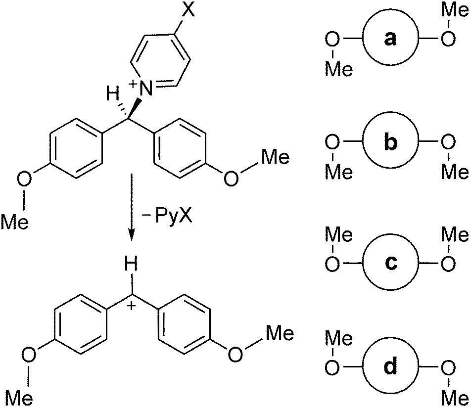
2.2.1 Conformationally mobile 4,4′-disubstituted benzhydrylpyridinium cations.
An example to illustrate the application of these relationships is provided by heterolysis of 4,4′-disubstituted benzhydrylpyridinium cations.41 These are reactions which satisfy Curtin–Hammett conditions, having low barriers for internal rotation of (for example) the methoxy substituents shown in Scheme 1. The four RS conformers lie within about 3 kJ mol−1 of each other and are separated by Gibbs-energy barriers of less than 20 kJ mol−1 at 298 K, as computed by means of the M06-2X/6-311+G(2d,p)/PCM = EtOH method.42 The vertical blue lines represent calculated Gibbs energies of activation for heterolysis of the C–N bond via each individual TS conformer, a to d, with respect the single RS conformer of lowest energy, namely a. Application of eqn (10) yields the apparent Gibbs energy of activation for the four parallel reactions, as shown by the dashed red line, which has a value less than any of the individual values for Δ‡Gi0 (where i = a, b, c or d). The mole fractions of the four RS conformers in this example are xRSa = 0.52, xRSb = 0.15, xRSc = 0.17, and xRSd = 0.15; the mole fractions of the four TS conformers are xTSa = 0.16, xTSb = 0.43, xTSc = 0.14, and xTSd = 0.27. The TS making the largest contribution to the overall reaction is the one with the largest mole fraction, but all four make significant contributions owing to their closeness in energy. The virtual TS is the weighted average of the four TS conformers (Fig. 4).
 |
| | Scheme 1 Top: Heterolysis of one conformer of 4,4′-dimethoxybenzhydrylpyridinium cation. Bottom: Cartoon representations for other reactant conformers a, b, c and d to illustrate methoxy-group orientations.42 | |
 |
| | Fig. 4 Individual and apparent Gibbs energies of activation for heterolysis of 4,4′-dimethoxy benzhydrylpyridinium computed with the M06-2X/6-311+G(2d,p)/PCM = EtOH method. (Reproduced from ref. 33 with permission). | |
3. Analogy between rate constant and electrical conductance
Just as the rate of a first-order reaction is given as the product of a rate constant and a concentration, so the current (I) flowing through an electrical circuit is the product of a conductance (C) and a potential difference (V).34,43–45
Adding branches in parallel within an electrical circuit increases the current flowing through the circuit for a given potential difference because the total conductance is increased and conversely the total resistance (the reciprocal of conductance) is decreased. The total conductance is the sum of the conductance Ci for each of the N parallel branches:
As seen in Section 2 above, the total rate constant for reactions in parallel is also the sum of the individual rate constants.
In this reviewer's experience, the kinetic behaviour of parallel reactions is more readily understandable than that of reactions in series, which is discussed below in Section 4. (Perhaps this is due to the relative familiarity of the concept of Boltzmann populations?) However, before entering discussion of the kinetics of consecutive reactions, it is helpful to consider the analogy of resistors in series. It seems to be much easier to access straightforward accounts of the characteristics of electrical circuits (online or in textbooks) than to find clear treatments of apparent rate constants for sequential multistep chemical reactions!
Since adding resistances in series within a circuit gives the total resistance as the sum of the individual resistances, the reciprocal of the corresponding total conductance is the sum of the reciprocals of the N individual conductances in series:
As seen in Section 4 below, the reciprocal of the total rate constant for series of reaction steps is also the sum of the reciprocals of the individual rate constants.
4. Multiple TSs in series
Many complex mechanisms involve two or more consecutive steps prior to an irreversible step that terminates a sequence of TSs in series. Many textbooks consider the kinetics of a simple two-step mechanism with a single high-energy intermediate, such as illustrated by Fig. 1 for the SN1 mechanism, in terms of two extreme cases: either (a) the Gibbs energy of TS1 is very much higher than that of TS2 (i.e. Δ‡G1 ≫ Δ‡G2) or (b) the Gibbs energy of TS1 is very much lower than that of TS2 (i.e. Δ‡G1 ≪ Δ‡G2). In case (b) the amount of intermediate formed in the rapid first step accumulates to a significant concentration before it decreases slowly by means of the slow second step; this type of mechanism will not be considered further here. In case (a), the intermediate reacts by the rapid second step as soon as it is formed by the slow first step, and therefore its concentration remains very low and approximately constant throughout the course of reaction. It is usual to apply the steady-state approximation to this case (Scheme 2),46 which will now be considered and extended to multiple steps involving TSs which are close in energy.
 |
| | Scheme 2 Two-step steady-state reaction showing alternative definition of rate constants. | |
4.1 Steady-state apparent rate constants for two-step mechanisms
Because the rates of formation and breakdown of the intermediate are approximately equal, rearrangement of eqn (15) allows the steady-state concentration [Int] of the intermediate (Scheme 2) to be determined (eqn (16)), and hence the overall rate of reaction is equal to the rate of the irreversible second step (eqn (17)) from which the apparent rate constant is easily identified.| | | k1[RS] − k−1[Int] − k2[Int]ss = 0 | (15) |
| | | ∴ [Int]ss = k1[RS]/(k−1 + k2) | (16) |
| | | Rate = k2[Int]ss = k1k2[RS]/(k−1 + k2) | (17) |
| | | kseriesapp = k1k2/(k−1 + k2) | (18) |
Note that the k1, k−1 and k2 in eqn (15)–(18) denote rate constants for individual forward or backward reaction steps and that the latter two both relate to the intermediate.
It is instructive to consider the reciprocal of kseriesapp, as in eqn (19).
| | | 1/kseriesapp = (k−1 + k2)/k1k2 = k−1/k1k2 + k2/k1k2 = 1/K1k2 + 1/k1 | (19) |
Here K1 is the equilibrium constant for step 1, and the product K1k2 is the net rate coefficient for step 2 with respect to RS (instead of Int), which is conveniently denoted by a superscript °, as in  . This equation can be expressed in terms of Gibbs energies relative to RS as the common reference state.
| |  | (20) |
| |  | (21) |
| |  | (22) |
The reciprocal of the apparent rate constant for the complex mechanism is the sum of the reciprocals of the rate constants for the two steps, each with respect to RS, and each of the exponentials in eqn (22) has a plus sign before the Gibbs energy of activation relative to RS. Clearly, the apparent Gibbs energy of activation must always be greater than the Gibbs energy difference between RS and either of the two TSs. Also, if the two TSs are of equal energy, then the value of Δ‡Gseriesapp is greater than either  or
or  by RTln2 (or 2.3RTlog102).
As with two reactions in parallel, the apparent Gibbs energy of activation for a reaction with two steps in series corresponds to the virtual TS. The contribution, wi, of each individual TSi to the overall activation energy is not its Boltzmann weighting but is given by an analogous eqn (23) in which the minus signs of eqn (3) are replaced by plus signs.
| |  | (23) |
The TS that makes the larger contribution is the one with the higher Gibbs energy, and the apparent Gibbs energy of activation is more than either of the values of  for the two steps. It may not be immediately obvious why the Gibbs energy of activation is not simply that involving the TS of higher Gibbs energy alone: it is often stated that the rate-limiting step is the slowest step47 or that involving the TS of highest energy.12 It is important to recognise that the overall rate of reaction through a sequence of steady-state steps is the same as the rate through any one of the individual TSs in series.34,48 Using eqn (23) and taking [RS] = 1 M (i.e. the standard state concentration), then the overall rate is given by eqn (24).
| |  | (24) |
The coefficient of the  rate constant for reaction through the TS of higher energy (in the two-step sequence) is not [RS] = 1 but w2 < 1. Although
  is larger than
  , the weighting factor w1 is smaller than w2, so that the apparent rate constant is the same regardless of which TS is considered. Whenever there are non-negligible values of wi for TSs other than the one of highest Gibbs energy, then the other TSs are kinetically significant to some extent; and because the weighting factor associated with the TS of highest Gibbs energy has a value less than unity, the apparent rate constant is less than the individual rate constant for that step, and the apparent Gibbs energy of activation is greater than that for that same step alone, and corresponds to a virtual TS as a weighted average rather than to any single TS for a single rate-limiting step.
4.1.1 Apparent KIE for two-step steady-state mechanism.
It is convenient to introduce a left superscript * to denote isotopic substitution (where * may represent 2H, 3H, 13C, 14C, etc.) in RS. The isotope effect on the apparent rate constant may be written as a weighted sum of the KIEs on each of the two steps, each with respect to RS (eqn (25)).| |  | (25) |
4.1.2 Complex Hammett plot for aryl semicarbazone formation.
Second-order rate constants measured for reaction of semicarbazide with a range of substituted aromatic benzaldehydes yielded a non-linear Hammett correlation against σ;49 the observation of a negative change in the slope as σ increased positively was interpreted as evidence for a change in rate-limiting step, from nucleophilic addition (step 1) for electron-donating substituents to dehydration (step 2) for electron withdrawing groups.49,50 Anderson and Jencks noted that the break in slope at σ = 0 was sharp, but it should be noted that there was a degree of uncertainty in each of the original rate-constant determinations, as well as a relative paucity of data points from which to construct each section of the plot.49 Williams51 reinterpreted the Hammett plot by suggesting that the data should be correlated by two linear segments with slopes tangential to the asymptotes of a theoretical curve obtained from an equation equivalent to eqn (26) (Fig. 5), which is obtained by substitution of Hammett equations addition (with ρ1 and c1) and dehydration (with ρ2 and c2). Furthermore, he commented that this curve lay log102 below the point of intersection of the two linear sections, in accordance with the TSs for steps 1 and 2 having equal energies, as noted above. In the light of the present discussion, it may be further commented that all points on the curve lying below the two intersecting straight lines correspond to virtual TSs.| | | log10{kcurveapp} = −log10[10−(ρ1σ + c1) + 10−(ρ2σ + c2)] | (26) |
 |
| | Fig. 5 Change in rate-limiting step for reaction of semicarbazide with substituted aromatic aldehydes evidenced by concave-upwards complex Hammett plot. (Adapted from ref. 51 with permission). | |
4.1.3 Gibbs energy profiles for change of rate-limiting step.
The numerical values on the vertical axis of the Hammett plot shown in Fig. 5 are proportional to Gibbs energies of activation for the addition–elimination reactions whose observed second-order rate constants were measured experimentally: Δ‡G° = −2.3RTlog10{kobs}, where the superscript ° denotes standard molar Gibbs energy. A separate Gibbs energy profile could be sketched for reaction of each substituted aromatic aldehyde. Fig. 6 depicts three cases to illustrate the effect of the change of rate-limiting step from (a) rate-limiting nucleophilic addition to (c) rate-limiting water elimination. As the substituent X becomes less electron-donating, the Gibbs energy for TS1 relative to RS decreases more rapidly than the energy of TS2 increases, so the apparent rate constant increases while w1 > w2 (and step 1 is predominantly rate-limiting) but then falls more gently when w1 < w2 (and the contribution of step 2 dominates).
 |
| | Fig. 6 Gibbs energy profiles to illustrate change in rate-limiting step for reaction of semicarbazide with substituted aromatic aldehydes: (a) rate-limiting addition (step 1), (b) steps 1 and 2 equally rate-limiting, (c) rate-limiting dehydration. | |
4.1.4 Variable KIE accompanying two-step nucleophilic displacement.
Heterolysis of a benzhydryl pyridinium salt (cf.Scheme 1) could be the first step of a displacement reaction in which a nucleophile other than solvent adds to the intermediate benzhydrylium cation in a second step, as in Scheme 3, where unsubstituted pyridine departs from the reactant (RS) in step 1 as the nucleofuge and 4-methylpyridine enters in step 2 as the nucleophile (Nu). This example has been considered in relation to how the apparent secondary KIE Hk/Dk varies with changing concentration of Nu in a computational simulation.52 If the concentration of each reactant species (RS and Nu) were equal to 1 M, then the standard molar Gibbs energy of the reaction shown in Scheme 2 was calculated (M06-2X/6-311+G(2d,p)/PCM = EtOH) to be exoergic, and the standard molar Gibbs energies of the two TSs were found to be close, with weightings factors w1 = 0.73 and w2 = 0.27. Because both steps were found to be isotopically sensitive, the apparent value of Hk/Dk was a weighted average of the effects on each of those steps, corresponding to a virtual TS (eqn (27), which is a specific case of eqn (25)).| |  | (27) |
 |
| | Scheme 3 Two-step nucleophilic displacement (L = H or D). | |
If such a reaction were to be performed experimentally to maximise the yield of the product, then equimolar concentrations of RS and Nu would not be employed; rather, an excess of Nu would be used to drive the reaction towards completion. As Fig. 7 shows, the apparent KIE varies between limiting values as the concentration ratio [Nu]/[RS] changes. The energies used to obtain the weighting factors by means of eqn (23) are not standard molar Gibbs energies, as that of Nu relative to RS now includes an extra term equal to −2.3RTlog10([Nu]/[RS]). As w1 approaches unity (and w2 → 0), so the apparent KIE tends towards the limit (at 298 K) of 1.139 for step 1 being completely rate limiting (green Gibbs energy profile); conversely, as w1 → 0 and w2 → 1, the apparent KIE tends towards the limit of 1.153 for step 2 being completely rate limiting (red Gibbs energy profile). The variation of apparent KIE value between these limits occurs over a relative Nu concentration range of 2 orders of magnitude, i.e. 0.1 < [Nu]/[RS] < 10.52
 |
| | Fig. 7 Variation of apparent 2° α-D KIE for the reaction of Scheme 3 as a function of the relative concentration of the nucleophile Nu to the substrate RS at 298 K. (Adapted from ref. 52 based under CC BY 4.0.) | |
4.2 Steady-state apparent rate constants for multiple steps in series
The expressions for the apparent rate constant and apparent Gibbs energy of activation are easily extended to an any number N of TSs in series for a multistep steady-state reaction, as in eqn (28) and (29), where each individual rate constant and each TS Gibbs energy is relative to the RS. Once again, the apparent Gibbs energy of activation is higher than any of the values of  for the individual steps, and the TS that makes the largest contribution is the one with the highest Gibbs energy.
| |  | (28) |
| |  | (29) |
4.2.1 Virtual TS for 3-step serial mechanism.
In order for an alkyl substrate to undergo inversion of stereochemistry in an SN2 mechanism it is necessary for nucleophilic displacement to be accompanied by alkyl-group rotation; unless this occurs, the staggered conformer of the RS would lead to an eclipsed conformer of the PS. An amusing example of this fact was noted in a computational study of the identity reaction of water with protonated t-butanol.53 It is normally assumed that a tertiary alkyl substrate undergoes solvolysis only by the SN1 mechanism, but the issue is whether the t-butyl cation does or does not exist as a discrete intermediate in water as modelled by a given theoretical method. The B3LYP/6-31G*/PCM = water method predicts that the H2O + tBuOH2+ → +H2OBut + OH2 identity reaction involves a series of three TSs, each of which involves the rotation of one methyl group, and two solvated tBu+-like intermediates, both of high energy. Inserting the computed TS energies into eqn (23) leads to weighting factors of 0.13, 0.74 and 0.13, respectively. The virtual TS is the weighted average of these three, and it would ‘look like’ the expected TS for concerted nucleophilic displacement; however, each of the individual TSs appears to involve only methyl-group rotation.33,53 The overall result is that both RS and PS have energetically favourable staggered conformations (Fig. 8).
 |
| | Fig. 8 Computed transition structures for individual steps of the identity reaction H2O + tBuOH2+ → +H2OBut + OH2 (B3LYP/6-31G*/PCM = water). | |
4.2.2 Multistep steady-state enzymic reactions.
Enzymic reactions are invariably multistep processes, and it is common to employ steady-state conditions in experimental investigations of kinetics and mechanism. A minimal mechanism is as shown in Scheme 4.
 |
| | Scheme 4 Minimal enzyme mechanism. | |
KIEs offer a powerful tool to probe enzyme mechanisms, and competition experiments are often employed in which an isotopically substituted substrate S* is mixed with unsubstituted substrate S and the observed rate-constant ratio (k/*k)seriesapp is determined by means of monitoring the isotopic composition of either starting material or product as a function of the extent of reaction. Neglecting the reverse of both steps 2 and 3 in Scheme 4 makes it equivalent to the simplest two-step steady-state mechanism already discussed. The steady-state expressions for [ES] and [ES*] in an intermolecular competition experiment are given by eqn (30) and (31).54
| | | k1([E] − [ES] − [ES*] − [EP] − [EP*]) [S] − (k−1 + k2) [ES] = 0 | (30) |
| | | *k1([E] − [ES] − [ES*] − [EP] − [EP*]) [S*] − (*k−1 + *k2) [ES*] = 0 | (31) |
Solving each equation for ([E] − [ES] − [ES*] − [EP] − [EP*]) and setting the resulting expressions equal yields, upon rearrangement, eqn (32).
| | | [ES]/[ES*] = {k1/(k−1 + k2)[S]]/{*k1([/(*k−1 + *k2) [S*]]} | (32) |
Since the steady-state rates are given by
| Rate = k2[ES] = kapp[E][S] and *Rate = *k2[ES*] = *kapp[E][S] |
then the ratio of apparent rate constants may be obtained as
eqn (33).
54| |  | (33) |
This expression for the apparent KIE is simply the ratio of eqn (18) for unsubstituted and substituted substrates, and it is couched in terms of microscopic rate constants for individual forward and reverse steps. It can be easily demonstrated that the apparent KIE is also equal to the ratio of the quantities Vmax/Km for the ‘light’ and ‘heavy’ substrates, where Vmax is the maximal velocity and Km is the Michaelis constant for the enzymic reaction.54,55
| |  | (34) |
The earlier derivation of eqn (25) involves what enzyme kineticists often refer to as net rate constants56 (in this case  and
and  ), which for each step are relative to the RS. Furthermore, it is clear that the RS for the KIEs under Vmax/Km (competitive) conditions is the unbound substrate and enzyme in solution.57
The complete expression for the apparent KIE of the minimal mechanism (Scheme 4) is given by eqn (35) in terms of microscopic rate constants for all three individual steps, where K1/*K1 and K2/*K2 are equilibrium isotope effects (EIEs) for the first and second steps.57
| |  | (35) |
It is conventional to denote the rate-constant ratios (for isotopically unsubstituted substrates) k2/k−1 = Cf and k−2/k3 = Cr as forward and reverse commitments to catalysis, respectively,58 and to assume that only one step is isotopically sensitive. Using this notation and assumption, the apparent KIE may be written as eqn (36).
| |  | (36) |
The ratio k2/*k2 for the single isotopically sensitive step is the ‘intrinsic’ KIE,59 which has usually been the quantity of interest to be extracted from the experimental data. In practice, even with the assumptions already made, there remain too many unknowns unless a further simplification is made, such as the assumption that Cr = 0 (i.e. step 3 in the minimal mechanism is irreversible, as in eqn (30)–(33)). For example, in a study of 5′-methylthioadenosine nucleosidase,60Cf was determined experimentally, and thus the intrinsic KIE on Vmax/Km (for * = tritium) was obtained as:
| | | (k2/*k2) = (k/*k)seriesapp(Cf + 1) − Cf | (37) |
Many enzyme-catalysed reactions involve many more steps than the minimal mechanism: Scheme 5 is an example of a steady-state reaction with five steps in series, for which the apparent KIE is given by eqn (38), which (once again) involves microscopic rate constants for individual steps.57 The point of presenting this unwieldy expression in full is to show how much more compact it is to relate each rate constant to RS, as in eqn (39), which is simply the sum of products of the weighting factor and the net rate constant for each of the steps in the steady-state sequence. The coefficients in the numerator of eqn (38) that appear in parentheses, and without any isotopic substitution, correspond to forward and reverse commitment factors, like the Cf and Cr of eqn (36), but now more complicated, and not very readily understandable.52 These factors are much more amenable to physical interpretation in terms of relative Gibbs energies of the TSs, as shown in eqn (40a)–(40e) and Fig. 9.
| |  | (38) |
| |  | (39) |
| |  | (40a) |
| |  | (40b) |
| |  | (40c) |
| |  | (40d) |
| |  | (40e) |
 |
| | Scheme 5 More-complex enzyme mechanism. | |
 |
| | Fig. 9 Gibbs energy profile for steady-state enzymic mechanism of Scheme 5 to illustrate the relationship of the TS weighting factors to Gibbs-energy differences between the TSs (only) and the dependence of commitment factors upon Gibbs-energy differences between intermediates and TSs. | |
From these expressions, it is clear that the denominator in eqn (38) is the sum of the exponential terms in eqn (40a)–(40e), and that the weighting factors of eqn (39) are related to the commitment factors.52 However, since the commitments factors involve ratios of microscopic rate constants that depend upon the Gibbs energies of intermediates and of TSs, whereas the weighting factors depend only on the relative Gibbs energies of the TSs, it may be argued that the latter provide a much simpler way to treat KIEs for complex steady-state enzyme mechanisms. Note that the choice of the reference energy for the weighting factors is arbitrary: in eqn (23) it was the Gibbs energy of RS, and in eqn (40a)–(40e) it is the Gibbs energy of TS3, but the same values arise from any choice of reference state.
| |  | (41a) |
| |  | (41b) |
| |  | (41c) |
| |  | (41d) |
| |  | (41e) |
and
| |  | (42) |
As before, the apparent KIE is the weighted average of the KIEs on each of the net rate constants  for the individual steps in the sequence. If any of these steps are isotopically insensitive, so that
  , the weighting factors for those steps still contribute to the apparent KIE, serving to reduce its value from the intrinsic KIE for a single isotopically sensitive step.
The essence of the above discussion may be found in several places within the chemical and biochemical literature, but (in this reviewer's opinion) the simplicity of the fundamental idea has sometimes been obscured by use of traditional enzymological nomenclature, notation, and formal mathematical presentation.61–67 The weighting factor wi has been called by a variety of names, e.g. kinetic significance,68 sensitivity index,62 control function,69 rate control coefficient70 or degree of rate control.65
4.2.3 Computational modelling of multistep steady-state enzymic reactions.
Modern methods of computational simulation now provide realistic tools, complementary with experiment, for investigation of mechanisms71 and KIEs72 for enzymic reactions. To date, the goal has usually been to achieve agreement between the KIE computed for a particular step of a proposed mechanism and the experimentally derived intrinsic KIE for an isotopically sensitive step. However, it has not always been appreciated that observed KIEs are often effects on Vmax/Km rather than on Vmax, due to the necessity of using a competition method with isotopes such as tritium or 18O that cannot be enriched to high degrees: there are examples to be found in the literature of computational studies where the RS has been taken to be the bound enzyme–substrate complex ES instead of the free substrate in solution (cf. ref. 73). In many cases it has been assumed (as noted above) that only one step is isotopically sensitive, as in the study of 5′-methylthioadenosine nucleosidase,60 in which computed KIEs for that single step were compared with the derived intrinsic KIEs. There is preliminary evidence (at least) that the initial step of substrate binding has EIEs differing non-negligibly from unity;52 if confirmed, this would invalidate the derivation of the intrinsic KIEs from the observed KIEs. Consequently, it has been suggested that a better way of using computational approaches to assist experimental interpretations would be to compare computed and observed apparent KIEs directly.52
By means of appropriate QM/MM methods74 it is possible to locate TSs and intermediates along a reaction pathway, to determine their relative Gibbs energies, and to evaluate their isotopic sensitivities. Thus, for any desired isotopic substitution, both the weighting factors wi and KIEs associated with individual kinetically significant TSs may be computed by means of eqn (43), where fs and fi indicate isotopic partition-function ratios (IPFRs) for free substrate in aqueous solution and for the ith enzymic TS, respectively, and the brackets 〈⋯〉 denote averaging over numerous thermally accessible configurations.72
| |  | (43) |
Despite the fact that computational simulations may also provide KIEs and EIEs for individual elementary steps, it may not be desirable to attempt comparison with experimentally derived intrinsic KIEs if there is any doubt associated with the validity of the latter.52 The direct comparison of apparent KIEs involves, of course, the virtual TS: computational simulation allows for better insight than previously available regarding the virtual TS structure as a weighted average of the contributing TSs.
5. Complex mechanisms with TSs in series and in parallel
Hydrolysis of p-nitroacetanilide in basic solution proceeds by a mechanism (Scheme 6) in which initial formation of a tetrahedral intermediate by nucleophilic addition is followed by an elimination step that may go by either or both of two parallel pathways. Analysis of observed variations in apparent β-deuterium KIEs with changing hydroxide ion concentration used the virtual TS approach.75 Defining net rate constants in terms of the microscopic rate constants shown in Scheme 6 allows the reciprocal of the of the apparent rate constant kapp (corrected from the observed rate constant for ionisation of the anilide substrate) to be written as eqn (44), where  ,
,  and
and  . The two reciprocal terms on the right-hand side of this expression correspond to the two steps of a serial mechanism but, since the second step involves two parallel paths, the denominator of the second term is the sum of the effective rate constants for the two paths.
| |  | (44) |
 |
| | Scheme 6 Mechanism for anilide hydrolysis in basic solution. | |
The apparent KIE for his complex mechanism is given by eqn (45), where the left-superscript * denotes CD3 instead of CH3 and the weighting factors are as in eqn (45).
| |  | (45) |
| |  | (46) |
At low [HO−], decomposition of the adduct initially gives CL3CO2H + NO2C6H4NH− (where L = H or D), whereas at high [HO−] there is competing decomposition of the deprotonated adduct (initially to CL3CO2− + NO2C6H4NH−). The apparent KIE rises from 0.967 in the least-basic solution to about 0.98 with increasing hydroxide-ion concentration and falls to 0.933 in the most-basic solution. These changes (along with an apparently anomalous temperature dependence) were best explained by a shift in limitation of the rate away from the k1 TS (Scheme 6) toward the k3 TS as [HO−] increased or as the temperature was raised.75
6. Rate-limiting steps or rate-determining states?
The usefulness of the concept of a rate-limiting (or rate-determining, or rate-controlling) step in a complex reaction mechanism has been questioned and discussed many times.69,76–78 Moreover, the idea is deeply engrained within transition-state theory that it is necessary only to consider the energy difference between the RS and the TS of highest energy, and that all other TSs and intermediates can be neglected.79 There are indeed many instances where a single TS does predominate exclusively in a multistep reaction mechanism, but it is evident from the above discussion that such a situation corresponds to the weighting factor for that step to be essentially equal to unity and for all others to be effectively zero. In his treatment of the kinetics for an unbranched sequence of reaction steps exhibiting uniform flux,34 Noyes suggested a pragmatic criterion of ‘1% significance’, meaning that TSs more than RTln(100) lower in energy than the one of highest energy could reasonably be ignored; at 298 K this equates to an energy difference of at least 11.4 kJ mol−1. The whole issue of the possibility that two or more TSs lie energetically within this amount of each other, and that therefore multiple steps may be kinetically significant, is the subject of the present review of the concept of the virtual TS as a weighted average of real TSs. There are many reactions with complex mechanisms that fall within the scope of this possibility, especially enzyme-catalysed reactions.
It may seem to go against the grain of ideas learned long ago that the apparent Gibbs energy of activation can depend upon contributions from multiple TS rather than just one, and that there is no single rate-limiting step. Does this not contravene the fact that the energy difference between the RS and the TS is a quasi-thermodynamic function of state that is completely independent of the path by which the one is converted to the other? How can it be that the presence of other TSs affects the observed magnitude of the Gibbs energy of activation? It is true, of course, that the experimentally derived Gibbs energy of activation for an elementary reaction does indeed depend only on the RS and TS, for there is no ambiguity about what the TS is. However, for complex mechanisms the real TSs for individual steps may be practically inaccessible to experiment, which yields only information relating to the virtual TS, and an apparent Gibbs energy of activation that is indeed a quasi-thermodynamic state function.
Kozuch and co-workers have helpfully suggested that it is better to replace the idea of a rate-determining step by that of a pair of rate-determining states, namely ‘the transition state and intermediate which exert the strongest effect on the overall rate with a differential change on their Gibbs energies.’77 Moreover, they have advocated powerfully for the adoption of their ‘energy span model’ in order to understand features of chemical kinetics, especially within catalytic cycles.80,81 This proposal is in complete accord with the position taken in the present review that employing Gibbs energy differences, related directly to net rate constants, provides a much simpler and compact way to understand apparent activation energies and KIEs. However, Kozuch seems usually to focus upon only a single rate-determining TS within his model, and discussion of multiple TSs being kinetically significant is mostly absent, although an energy profile discussed for gold-catalysed ethane hydrogenation82 does contain two TSs of similar energy, with ‘degrees of turnover frequency control’ (XTOF,T) values that are equivalent to the TS weighting factors wi described in this review.
7. Concluding remarks
The concept of the virtual TS arose within the context of a discussion of alternative paradigms for understanding the origins of enzyme catalytic power. The conventional set of descriptions current at that time were labelled as ‘canonical’ formulations, which omitted or de-emphasized the TS but which were correct in principle.3 In contrast, Schowen proposed an alternative ‘fundamentalist’ formulation that ‘dwells on transition-state language to the exclusion of other descriptive apparatus.’3 (The labels were coined with tongue in cheek to make a point.) He noted that kinetically based probes of reaction mechanism were interpreted by considering how a perturbing variable (e.g. concentration, temperature, pressure, substrate structure or isotopic composition) affected the Gibbs energy of activation; also, since the response of the RS was likely to be reasonably well known, the interpretation centred on the TS. While this was a straightforward task for reactions involving a single rate-limiting TS, more complex situations required more careful analysis, in which the idea of the virtual TS was introduced. It is worthwhile to consider the following prescient quote from Schowen's chapter.
‘It may very well be, then, that in the future when many transition-state structures are understood and their use in predicting kinetic responses is well advanced the common technique will be to construct deliberately from known, real individual transition-state structures an appropriate virtual structure for use in rate prediction for a given reaction under certain conditions. In the meantime, however, the problem is likely to be seen from the opposite perspective, and the difficulty will be considered to lie in recognizing when one is dealing with a virtual transition state and when one has a “pure” transition state in hand. One will also desire techniques for dissecting the contributing structures out of the virtual hybrid and establishing the real, individual transition-state structures.’3
The virtual TS concept was subsequently adopted by some of Schowen's co-workers for a while,27,68,77,83 but has since been generally neglected, perhaps because of the practical difficulty of ‘dissecting the contributing structures’ from a virtual TS. The motivation for seeking now to revive the concept and to highlight its potential utility comes largely from an awareness that modern methods of computational simulation allow for reactions paths and TSs of complex mechanisms to be studied and their relative Gibbs energies and isotopic sensitivities (not to mention other properties) to be determined with increasing degrees of reliability. This opens the prospect of having a viable dissection tool to assist the interpretation of experimentally determined apparent activation energies and KIEs, leading to better understanding of complex mechanisms in chemistry and biochemistry.
Conflicts of interest
There are no conflicts to declare.
Data availability
No primary research results, software or code have been included and no new data were generated or analysed as part of this review.
Acknowledgements
I am grateful to Dr Harvey Dale (MRC Cambridge), Dr Jack Glancy (GSK), Prof. Vicent Moliner and Dr Katarzyna Świderek (Universitat Jaume I), and Prof. Iñaki Tuñón (Universitat de València) for helpful discussions.
Notes and references
-
S. G. Waley, Mechanisms of Organic and Enzymic Reactions, Clarendon Press: Oxford University Press, 1962, p. 55 Search PubMed.
- I. H. Williams, Chem. Soc. Rev., 1993, 22, 277–283 RSC.
-
R. L. Schowen, in Transition States of Biochemical Processes, ed. R. D. Gandour and R. L. Schowen, Plenum, 1978, pp. 109–111 Search PubMed.
- C. L. Perrin, I. Agranat, A. Bagno, S. E. Braslavsky, P. A. Fernandes, J.-F. Gal, G. C. Lloyd-Jones, H. Mayr, J. R. Murdoch, N. S. Nudelman, L. Radom, Z. Rappoport, M.-F. Ruasse, H.-U. Siehl, Y. Takeuchi, T. T. Tidwell, E. Uggerud and I. H. Williams, Pure Appl. Chem., 2022, 94, 353–534 CrossRef CAS.
- H. Eyring and M. Polanyi, Z. Phys. Chem., Abt. B, 1931, 12, 279–311 CAS.
- I. Tuñón and I. H. Williams, Adv. Phys. Org. Chem., 2019, 53, 29–68 CrossRef.
- G. Porter, Chem. Soc. (London) Spec. Publ., 1962, 16, 25 Search PubMed.
-
E. S. Gould, Mechanism and structure in organic chemistry, Holt, Rinehart and Winston, New York, 1959 Search PubMed.
-
R. Stewart, The investigation of organic reactions, Prentice-Hall, Englewood Cliffs, 1966 Search PubMed.
-
P. Sykes, A guidebook to mechanism in organic chemistry, Longman, 6th edn, 1986 Search PubMed.
-
H. Maskill, The physical basis of organic chemistry, Oxford University Press, Oxford, 1985 Search PubMed.
-
E. V. Anslyn and D. A. Dougherty, Modern physical organic chemistry, University Science Books, 2006 Search PubMed.
-
P. Vogel and K. N. Houk, Organic chemistry: theory, reactivity and mechanisms in modern synthesis, Wiley-VCH, Weinheim, 2019 Search PubMed.
- D. Oancea and L. de Maeyer, Prog. React. Kinet., 1994, 19, 431–457 CAS.
- K. Ishida, K. Morokuma and A. Komornicki, J. Chem. Phys., 1977, 66, 2153–2156 CrossRef CAS.
-
J. Dreyer, G. Brancato, E. Ippoliti, V. Genna, M. de Vivo, P. Carloni and U. Rothlisberger, in Simulating Enzyme Reactivity: Computational Methods in Enzyme Catalysis, ed. I. Tuñón and V. Moliner, Royal Society of Chemistry, Cambridge, 2017 Search PubMed.
-
J. Smiatek, N. Hansen and J. Kästner, in Simulating Enzyme Reactivity: Computational Methods in Enzyme Catalysis, ed. I. Tuñón and V. Moliner, Royal Society of Chemistry, Cambridge, 2017 Search PubMed.
- M. Szwarc, Chem. Soc. (London) Spec. Publ., 1962, 16, 25–27 Search PubMed.
-
W. J. Hehre, L. Radom, P. V. R. Schleyer and J. A. Pople, Ab Initio Molecular Orbital Theory, Wiley-Interscience, New York, 1986 Search PubMed.
- J. Tomasi, B. Mennucci and R. Cammi, Chem. Rev., 2005, 105, 2999–3094 CrossRef CAS PubMed.
- D. G. Truhlar and B. C. Garrett, Acc. Chem. Res., 1980, 13, 440–448 CrossRef CAS.
-
F. A. Carroll, Perspectives on Structure and Mechanism in Organic Chemistry, Brooks/Cole, Pacific Grove, CA, 1998 Search PubMed.
-
Transition States of Biochemical Processes, ed. R. D. Gandour and R. L. Schowen, Plenum, 1978 Search PubMed.
-
M. Page and A. Williams, Organic and Bio-organic Mechanisms, Addison Wesley Longman, 1997 Search PubMed.
- J. K. Lassila, J. G. Zalatan and D. Herschlag, Annu. Rev. Biochem., 2011, 80, 669–702 CrossRef CAS PubMed.
- V. L. Schramm, Annu. Rev. Biochem., 2011, 80, 703–732 CrossRef CAS PubMed.
- R. L. Stein, J. Org. Chem., 1981, 46, 3328–3330 CrossRef CAS.
- V. Gold, Trans. Faraday Soc., 1964, 60, 738–739 RSC.
- Although there is a very long history within physical organic chemistry of taking the logarithms of rate constants (as in, for example, the Hammett equation – but certainly predating Hammett's classic textbook41), it is mathematical nonsensical to take a logarithm (or an exponential) of any quantity that is not a pure number. In practice, when ‘log10k’ is written, it is tacitly interpreted as meaning ‘take the logarithm of the numerical value of the rate constant k’ while leaving aside its unit (e.g. s−1 or M−1 s−1). The IUPAC recommendation4 is to employ the reduced rate constant {k}, which is the dimensionless ratio of the rate constant to its unit: {k} = k/[k], where [k] denotes the unit of k. This practice not only provides for clarity of thought but is necessary for chemistry in the digital age to avoid errors in computational operations. RSC Publishing has long encouraged the labelling of graphical axes and tabular entries as dimensionless quantities (e.g. k/s−1).
-
P. Sykes, A guidebook to mechanism in organic chemistry, Longman, 6th edn, 1986 Search PubMed.
-
M. Page and A. Williams, Organic and bio-organic mechanisms, Longman, 1997 Search PubMed.
- M.-F. Ruasse and J.-E. Dubois, J. Org. Chem., 1972, 37, 1770–1778 CrossRef CAS.
- I. H. Williams, Pure Appl. Chem., 2025 DOI:10.1515/pac-2025-0453.
- R. M. Noyes, Prog. React. Kinet., 1964, 2, 339–362 Search PubMed.
- J. I. Seeman, J. Chem. Educ., 1986, 63, 42–48 CrossRef CAS.
- J. I. Seeman, Chem. Rev., 1988, 83, 83–134 CrossRef.
-
E. L. Eliel, Stereochemistry of Carbon Compounds, McGraw-Hill, 1962 Search PubMed.
- S. Winstein and N. J. Holness, J. Am. Chem. Soc., 1955, 77, 5562–5578 CrossRef CAS.
- D. Y. Curtin, Rec. Chem. Prog., 1954, 16, 111 Search PubMed.
- J. E. Baldwin, A. S. Raghavan, B. A. Hess and L. Smentek, J. Am. Chem. Soc., 2006, 128, 14854–14862 CrossRef CAS PubMed.
- M. Matić and B. Denegri, ChemistrySelect, 2021, 6, 2410–2423 CrossRef.
- I. H. Williams, J. Phys. Org. Chem., 2022, e4312 CrossRef CAS.
- J. A. Christiansen, Z. Phys. Chem., 1936, 33B, 145–155 CrossRef.
- W. J. Ray, Biochemistry, 1983, 22, 4625–4637 CrossRef CAS PubMed.
- S. Kozuch, ACS Catal., 2015, 5, 5242–5255 CrossRef CAS.
-
J. I. Steinfeld, J. S. Francisco and W. L. Hase, Chemical Kinetics and Dynamics, Prentice Hall, Englewood Cliffs, 1989 Search PubMed.
-
P. Vogel and K. N. Houk, Organic Chemistry: Theory, Reactivity and Mechanisms in Modern Synthesis, Wiley-VCH, Weinheim, 2019 Search PubMed.
-
L. P. Hammett, Physical organic chemistry, McGraw-Hill, New York, 1940 Search PubMed.
- D. S. Noyce, A. T. Bottini and S. G. Smith, J. Org. Chem., 1958, 23, 752–753 CrossRef CAS.
- B. M. Anderson and W. P. Jencks, J. Am. Chem. Soc., 1960, 82, 1773–1777 CrossRef CAS.
-
A. Williams, Free energy relationships in organic and bioorganic chemistry, Royal Society of Chemistry, Cambridge, 2003 Search PubMed.
- I. H. Williams, J. Phys. Chem. B, 2025, 129, 3604–3609 CrossRef CAS PubMed.
- G. D. Ruggiero and I. H. Williams, J. Chem. Soc., Perkin Trans. 2, 2001, 448–458 RSC.
-
L. Melander and W. H. Saunders, Reaction Rates of Isotopic Molecules, Wiley-Interscience, New York, 1980 Search PubMed.
- H. Simon and D. Palm, Angew. Chem., Int. Ed. Engl., 1966, 5, 920–933 CrossRef CAS.
- W. W. Cleland, Biochemistry, 1975, 14, 3220–3224 CrossRef CAS PubMed.
-
B. E. Lewis and V. L. Schramm, in Isotope Effects in Chemistry and Biology, ed. A. Kohen and H.-H. Limbach, CRC Press, Boca Raton, 2006, pp. 1019–1053 Search PubMed.
- D. B. Northrop, Biochemistry, 1975, 14, 2644–2651 CrossRef CAS PubMed.
-
D. B. Northrop, in Enzyme Mechanism from Isotope Effects, ed. P. F. Cook, CRC Press, Boca Raton, 1991 Search PubMed.
- V. Singh and V. L. Schramm, J. Am. Chem. Soc., 2007, 129, 2783–2795 CrossRef CAS PubMed.
- T. Yomo, T. Yamano, K. Yamamoto and I. Urabe, J. Theor. Biol., 1977, 188, 301–312 CrossRef PubMed.
- W. J. Ray, Biochemistry, 1983, 22, 4625–4637 CrossRef CAS PubMed.
- M. W. Ruszczycky and V. E. Anderson, J. Theor. Biol., 2006, 243, 328–342 CrossRef CAS PubMed.
- M. W. Ruszczycky and H.-W. Liu, Methods Enzymol., 2017, 596, 459–499 CAS.
- Z. Mao and C. T. Campbell, ACS Catal., 2020, 10, 4181–4192 CrossRef CAS.
- H. J. A. Dale, A. G. Leach and G. C. Lloyd-Jones, J. Am. Chem. Soc., 2021, 143, 21079–21099 CrossRef CAS PubMed.
- C. Park, J. Chem. Educ., 2022, 99, 2556–2562 CrossRef CAS.
- F. J. Alvarez, J. Ermer, G. Hübner, A. Schellenberger and R. L. Schowen, J. Am. Chem. Soc., 1991, 113, 8402–8409 CrossRef CAS.
- K. J. Laidler, J. Chem. Educ., 1988, 65, 250–254 CrossRef CAS.
- J. Sudi, Biochim. Biophys. Acta, Protein Struct. Mol. Enzymol., 1997, 1341, 108–136 CrossRef CAS PubMed.
-
K. E. Ranaghan and A. J. Mulholland, in Simulating Enzyme Reactivity: Computational Methods in Enzyme Catalysis, ed. I. Tuñón and V. Moliner, Royal Society of Chemistry, Cambridge, 2017 Search PubMed.
-
P. B. Wilson and I. H. Williams, in Simulating Enzyme Reactivity: Computational Methods in Enzyme Catalysis, ed. I. Tuñón and V. Moliner, Royal Society of Chemistry, Cambridge, 2017 Search PubMed.
- S. Martí, V. Moliner, I. Tuñón and I. H. Williams, J. Phys. Chem. B, 2005, 109, 3707–3710 CrossRef PubMed.
- A cautionary note: it remains a severe challenge, even for current state-of-the-art methods, to predict relative Gibbs energies accurately and reliably for TSs of similar energy.
- R. L. Stein, H. Fujihara, D. M. Quinn, G. Fischer, G. Küllertz, A. Barth and R. L. Schowen, J. Am. Chem. Soc., 1984, 106, 1457–1461 CrossRef CAS.
- J. R. Murdoch, J. Chem. Educ., 1981, 58, 32–36 CrossRef CAS.
- S. Kozuch and J. M. L. Martin, ChemPhysChem, 2011, 12, 1413–1418 CrossRef CAS PubMed.
- D. Y. Murzin, Reactions, 2020, 1, 37–46 CrossRef.
-
S. Glasstone, K. J. Laidler and H. Eyring, The theory of rate processes, McGraw-Hill, New York, 1941 Search PubMed.
- S. Kozuch and S. Shaik, Acc. Chem. Res., 2011, 44, 101–110 CrossRef CAS PubMed.
- E. Solel, N. Tarranam and S. Kozuch, Chem. Commun., 2019, 55, 5306–5322 RSC.
- S. Kozuch, Wiley Interdiscip. Rev.:Comput. Mol. Sci., 2012, 2, 795–815 CAS.
- D. M. Quinn, Chem. Rev., 1987, 87, 955–979 CrossRef CAS.
|
| This journal is © The Royal Society of Chemistry 2025 |
Click here to see how this site uses Cookies. View our privacy policy here. 
 Open Access Article
 This Open Access Article is licensed under a


 . This equation can be expressed in terms of Gibbs energies relative to RS as the common reference state.


 or
or  by RT
by RT
 for the two steps. It may not be immediately obvious why the Gibbs energy of activation is not simply that involving the TS of higher Gibbs energy alone: it is often stated that the rate-limiting step is the slowest step47 or that involving the TS of highest energy.12 It is important to recognise that the overall rate of reaction through a sequence of steady-state steps is the same as the rate through any one of the individual TSs in series.34,48 Using eqn (23) and taking [RS] = 1 M (i.e. the standard state concentration), then the overall rate is given by eqn (24).
 rate constant for reaction through the TS of higher energy (in the two-step sequence) is not [RS] = 1 but w2 < 1. Although
  is larger than
  , the weighting factor w1 is smaller than w2, so that the apparent rate constant is the same regardless of which TS is considered. Whenever there are non-negligible values of wi for TSs other than the one of highest Gibbs energy, then the other TSs are kinetically significant to some extent; and because the weighting factor associated with the TS of highest Gibbs energy has a value less than unity, the apparent rate constant is less than the individual rate constant for that step, and the apparent Gibbs energy of activation is greater than that for that same step alone, and corresponds to a virtual TS as a weighted average rather than to any single TS for a single rate-limiting step.


 for the individual steps, and the TS that makes the largest contribution is the one with the highest Gibbs energy.


 and
and  ), which for each step are relative to the RS. Furthermore, it is clear that the RS for the KIEs under Vmax/Km (competitive) conditions is the unbound substrate and enzyme in solution.57


 for the individual steps in the sequence. If any of these steps are isotopically insensitive, so that
  , the weighting factors for those steps still contribute to the apparent KIE, serving to reduce its value from the intrinsic KIE for a single isotopically sensitive step.
 ,
,  and
and  . The two reciprocal terms on the right-hand side of this expression correspond to the two steps of a serial mechanism but, since the second step involves two parallel paths, the denominator of the second term is the sum of the effective rate constants for the two paths.


