
 Open Access Article
 This Open Access Article is licensed under a Creative Commons Attribution-Non Commercial 3.0 Unported Licence
Employing a similar acceptor material as the third component to enhance the performance of organic solar cells†
Kun
Wang
 *a,
Haolei
Bai
a,
Cheng
Zhang
ab,
Chunxiao
Sun
a,
Shuyang
Sang
b,
Yuechen
Li
b,
Zekun
Chen
b,
Jia’nan
Hu
a,
Xiaojun
Li
b,
Lei
Meng
*b and
Yongfang
Li
b
*a,
Haolei
Bai
a,
Cheng
Zhang
ab,
Chunxiao
Sun
a,
Shuyang
Sang
b,
Yuechen
Li
b,
Zekun
Chen
b,
Jia’nan
Hu
a,
Xiaojun
Li
b,
Lei
Meng
*b and
Yongfang
Li
b
aSchool of Materials and Chemical Engineering, Zhongyuan University of Technology, Zhengzhou, 451191, China. E-mail: kwang@zut.edu.cn
bBeijing National Laboratory for Molecular Sciences, CAS Key Laboratory of Organic Solids, Institute of Chemistry, Chinese Academy of Sciences, Beijing, 100190, China. E-mail: menglei@iccas.ac.cn
First published on 19th June 2024
Abstract
We synthesized two derivatives of Y6, namely Y-TNF and Y-TN. Compared to Y6, these two derivatives possess fluorinated and non-fluorinated extended terminal groups, respectively. Y-TNF exhibits a red-shifted absorption compared to Y-TN, a narrower bandgap, and a better matched energy level to the donor material PM6. Hence, Y-TNF demonstrates better photovoltaic performance. The incorporation of Y-TN further enhances the photovoltaic performance of binary PM6:Y-TNF devices due to its good compatibility and intermolecular interactions with Y-TNF, resulting in improved charge transport and reduced non-radiative energy loss. The ternary organic solar cells (OSCs) offer a higher device efficiency of 16.63% with a high open-circuit voltage of 0.857 V, a high short-circuit current density of 25.84 mA cm−2, and a high fill factor of 75.10%. The results show that incorporating a similar acceptor material as the third component is an effective strategy to enhance the performance of OSCs.
1. Introduction
Recent advancements in the field of organic solar cells (OSCs) have been propelled by the development of narrow bandgap small molecule acceptors (SMAs). Since ITIC1 was reported in 2015, the A–D–A-type SMAs have had great success.2,3 With the development of such materials, the power conversion efficiency (PCE) of OSCs has been increased to 18%.4 This is due to the outstanding advantages of these acceptor materials, such as strong and wide absorption in the visible and near infrared regions, easily regulated electron energy levels, and high carrier mobility.5 The crystallinity and miscibility of the A–D–A SMAs and donor materials in their blend films can also be fine-tuned.6 And then, with the advent of Y6 and its derivatives, the OSCs have culminated in a PCE surpassing 19% for single-junction photovoltaic devices.7–25 This achievement has bolstered confidence and escalated expectations for their commercial viability. The Y-series of SMAs employ benzothiadiazole as the central electron-withdrawing unit, and by augmenting the number of electron donor/acceptor units to form an A–DA′D–A molecular structure that augments electron transfer efficiency. Additionally, the ‘banana’ shape of these molecules facilitates enhanced intermolecular stacking.26,27 The two strong electron-withdrawing end groups exert a profound influence on the performance metrics of OSC devices, including the open-circuit voltage (Voc), short-circuit current density (Jsc), and fill factor (FF). Compared to altering the molecular skeleton or alkyl side chains, modifying the end groups represents a straightforward approach that can significantly enhance the performance of OSC devices.12,18,28–37In the recent developments of OSCs, the ternary blending strategy has gained widespread adoption to enhance the PCE. The Y series of SMAs have been meticulously explored for this purpose. Ding et al. employed a ternary addition approach to modulate the film morphology of the device, achieving a high FF exceeding 80%, with significant suppression of non-radiative recombination.38 Huang et al. engineered a ternary OSC with an active layer thickness of 300 nm, attaining an efficiency surpassing 18%.39 Fan et al. utilized a new Y-series acceptor in their ternary device, culminating in an impressive PCE of 19.23%.40 Actually, the third component within OSCs serves a dual purpose, influencing both blend morphology optimization and carrier dynamics management. In ternary OSCs, the employment of two similar small molecule acceptors ensures good compatibility between the individual components. This facilitates precise adjustments to the morphology of the ternary blends, thereby optimizing Jsc and FF. Moreover, alloyed acceptor structural domains can be readily obtained by minimizing the structural disparity between the guest and main acceptors.41–43 Consequently, OSCs usually demonstrate suppressed charge recombination and enhanced photon conversion efficiency.44–49 This is attributable to energy transfer and a parallel-like morphology coexisting due to complementary absorption and reduced compatibility of the third component with the host material. Similarly, charge transfer and alloy-like morphology coexist due to the cascade energy level arrangement and good compatibility of the third component with the host material.4,40,50–54 Employing similar materials for the third component can augment the compatibility between different components of the device, thus improving the charge transfer efficiency and overall performance. Additionally, a comparable structure can alleviate the complexity associated with synthesizing and producing the material.
In this study, we employed the extended end group method to synthesize two SMAs, Y-TNF and Y-TN.55 Consistent with previous research, the fluorinated end group acceptor demonstrated better performance compared to its non-fluorinated counterpart in binary systems. Notably, the incorporation of Y-TN as a third component can led to further enhancements in the performance of devices utilizing the PM6:Y-TNF active layer. A comprehensive investigation has revealed that the incorporation of Y-TN enhances the compatibility among diverse components, augments their crystallinity, bolsters the charge transfer efficiency, and diminishes the non-radiative loss. Consequently, this augmentation ameliorates the performance of binary OSC devices and proffers conceptual underpinnings for ternary OSC methodologies.
2. Results and discussion
Fig. 1a illustrates the chemical structuress of Y-TNF and Y-TN, with their respective synthetic schemes provided in Schemes S1 and S2 (ESI†) (the structural characterization results are shown in Fig. S1–S6 in the ESI†). The UV absorption spectra of Y-TNF and Y-TN in solid film and chloroform solution are depicted in Fig. 1b and Fig. S10 (ESI†), respectively. As demonstrated in Fig. 1b, both materials exhibit complementary absorption to the donor material PM6. The solid film absorption peak for Y-TN is observed at 814 nm, while the fluorinated derivative Y-TNF displays a red-shifted absorption spectrum compared to Y-TN, with its peak at 844 nm (Table S1, ESI†). Y-TN shows pronounced shoulder peaks at 350 nm, 550 nm, and 725 nm, indicating enhanced light absorption capabilities.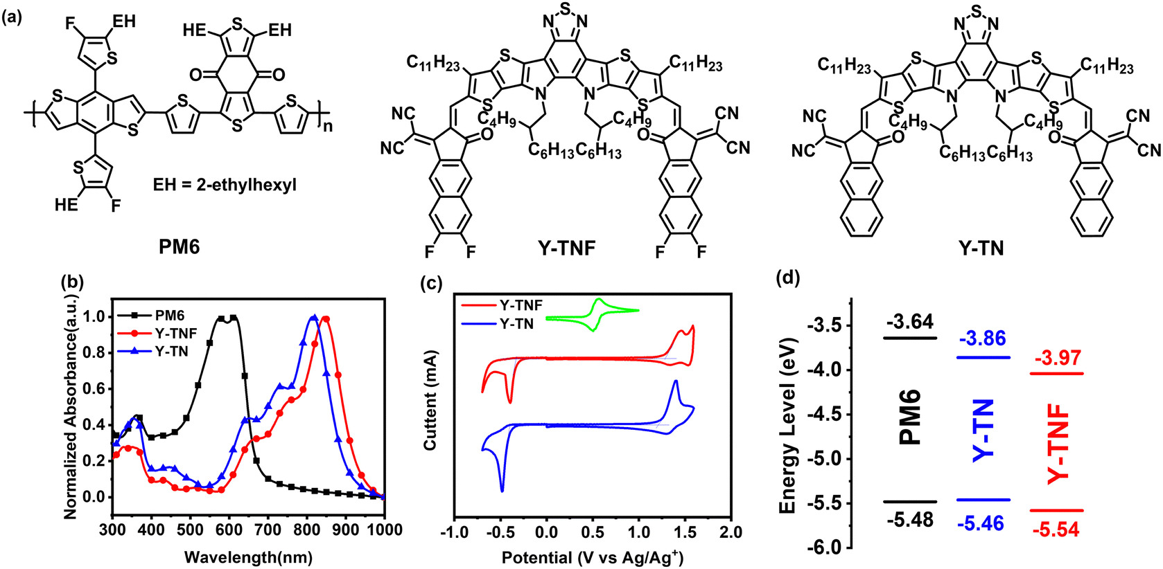 | ||
| Fig. 1 (a) The chemical structures of PM6, Y-TNF, and Y-TN; (b) the UV-vis absorption spectra of PM6, Y-TNF, and Y-TN in a solid film; (c) the cyclic voltammograms of Y-TNF and Y-TN; (d) energy levels diagram of PM6, Y-TNF, and Y-TN. | ||
The density distributions of electron clouds and the geometries of the frontier orbitals for Y-TNF and Y-TN materials were examined utilizing density-functional theory (DFT), as depicted in Fig. S7 (ESI†). Both Y-TNF and Y-TN exhibited substantial planarization. The highest occupied molecular orbital (HOMO) energy level (EHOMO) and the lowest unoccupied molecular orbital (LUMO) energy level (ELUMO) of Y-TNF experienced a slight downward shift upon the incorporation of fluorine atoms, resulting in a narrower bandgap compared to Y-TN. This narrower bandgap aligns with the trend observed from UV spectroscopic mappings (Table S1, ESI†). The electrostatic potential diagrams illustrated in Fig. S9 (ESI†) reveal that Y-TNF possesses elevated electronegativity due to the extended end group, and the addition of fluorine atoms augments the electron-withdrawing capability of the end group. The EHOMO and ELUMO values for Y-TNF and Y-TN were measured through cyclic voltammetry and determined according to the onset oxidation/reduction potentials obtained from their cyclic voltammograms.56 The EHOMO values were recorded as −5.54 eV for Y-TNF and −5.46 eV for Y-TN, while the ELUMO values were −3.97 eV for Y-TNF and −3.86 eV for Y-TN, respectively, as shown in Fig. 1d. These findings are in agreement with those derived from DFT calculations. It should be noted that the EHOMO energy level of Y-TN is slightly higher than that of the donor material PM6. The suboptimal alignment of the defective energy level results in diminished binary photovoltaic performance of the PM6:Y-TN combination. In addition, the dipole moment (μ) calculated for Y-TNF and Y-TN was 4.91 Debye and 8.67 Debye, respectively (Fig. S7, ESI†). The dipole moment directions of Y-TNF and Y-TN are shown in Fig. S8 (ESI†).
In grazing incidence wide-angle X-ray scattering (GIWAXS) measurements (Fig. 2 and Table S2, ESI†), the stacking of the alkyl chains induces Y-TNF and Y-TN to exhibit relatively well-defined (100) diffraction peaks along the in-plane (IP) and out-of-plane (OOP) direction (represented by qxy and qz, respectively). Both Y-TNF/Y-TN display distinct (100) diffraction peaks at 0.37 Å−1 and 0.4 Å−1 along the IP direction with corresponding d-spacing values of 16.98 Å and 16.53 Å, respectively. Additionally, distinct (010) π–π stacking peaks were observed for Y-TNF and Y-TN at qz = 1.67 Å−1 and 1.70 Å−1, along the OOP direction with respective d-spacing values of 3.74 Å and 3.67 Å. These observations indicate that both Y-TNF and Y-TN solid films have a preferred face-to-face alignment with the substrate.
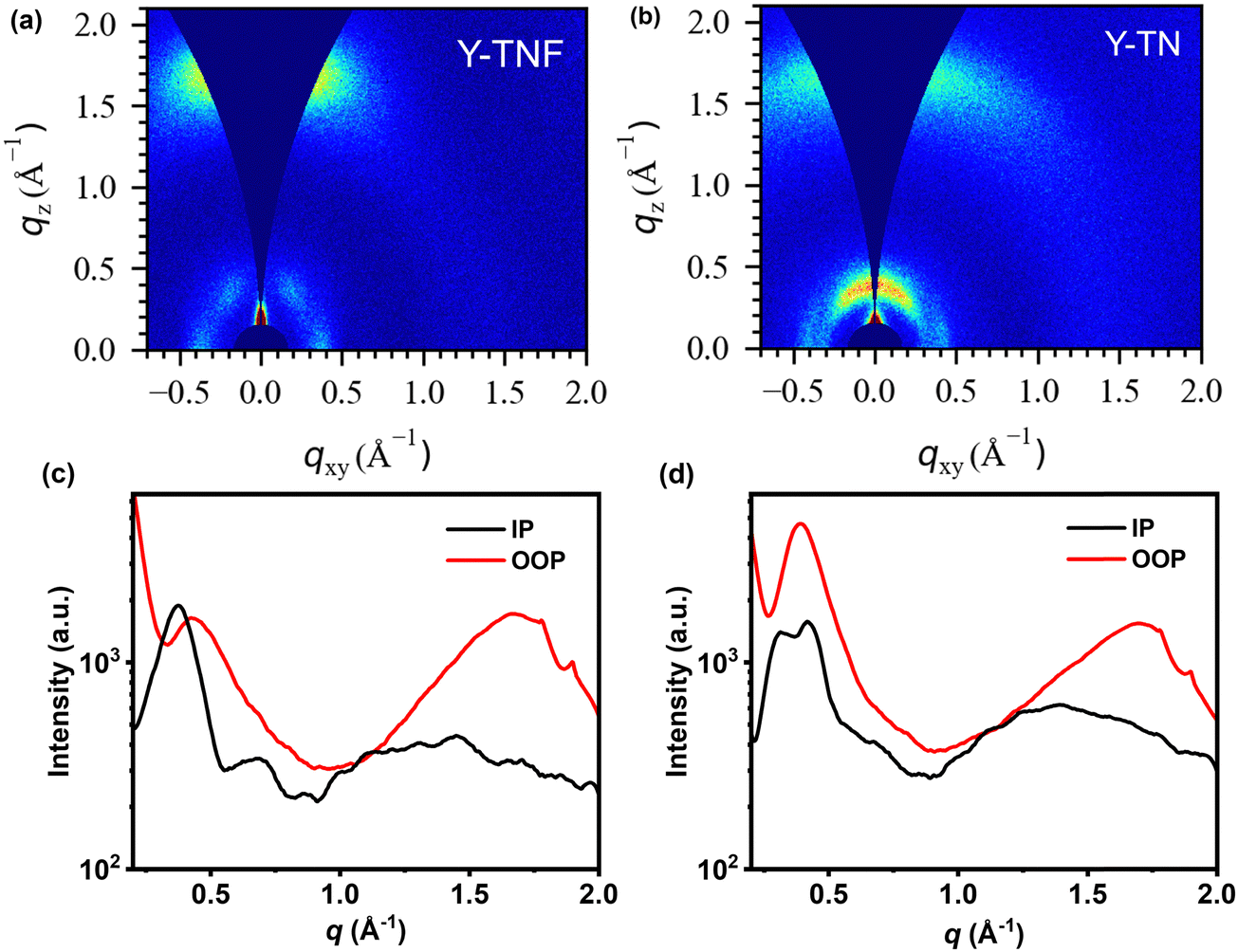 | ||
| Fig. 2 (a) The two-dimensional GIWAXS patterns of Y-TNF pure film, (b) the two-dimensional GIWAXS patterns of Y-TN pure film, (c) the corresponding in-plane and out-of-plane profiles under Y-TNF pure film optimal conditions, and (d) the corresponding in-plane and out-of-plane profiles under Y-TN pure film optimal conditions. | ||
To examine the photovoltaic properties of Y-TNF and Y-TN, OSCs devices were fabricated with the structure: ITO/PEDOT:PSS/active layer/PDINN/Ag (100 nm). The optimization process and corresponding data are presented in Fig. S11–S16 and Tables S3–S8 (ESI†). Device performance was optimized by determining the optimal addition ratio of the third component, Y-TN, as well as the effects of different additives (1,8-diiodooctane (DIO) and 1-chloronaphthalene (CN)), additive content (0%, 0.25%, and 0.5%), thermal annealing temperature (TA) (90 °C, 100 °C, and 110 °C), and TA duration (5 min, 10 min, and 15 min). The PM6:Y-TNF:Y-TN-based device achieved an impressive performance of 16.63% with a Voc of 0.857 V, high Jsc of 25.84 mA cm−2 and high FF of 75.10%, when the D![[thin space (1/6-em)]](https://www.rsc.org/images/entities/char_2009.gif) :A ratio was 1:1:0.1 (w/w/w), DIO was used as an additive (0.25%, v/v), and TA treatment was performed at 100 °C for 5 min. In contrast, the PM6:Y-TNF-based OSCs showed a PCE of 15.93% (Fig. 3 and Table 1), the OSCs based on PM6:Y-TN blend film only exhibited a PCE of 10.24% under the same conditions (Fig. S16 and Table S8, ESI†). In the external quantum efficiency (EQE) test, the EQE values of the ternary device were larger than those of the binary device at 450–550 nm and 700–850 nm after the introduction of the third component, Y-TN. Fluorine atoms have strong electronegativity and a small size, which can enhance intermolecular interactions.57–59 The introduction of fluorine atoms in Y-TNF can reduce the EHOMO and increase Jsc. However, it may also cause a deterioration in solubility and affect the morphology of the active layer film to some extent. In contrast, the introduction of a similar material, Y-TN, can enhance the FF of the device and effectively improve intermolecular stacking.
:A ratio was 1:1:0.1 (w/w/w), DIO was used as an additive (0.25%, v/v), and TA treatment was performed at 100 °C for 5 min. In contrast, the PM6:Y-TNF-based OSCs showed a PCE of 15.93% (Fig. 3 and Table 1), the OSCs based on PM6:Y-TN blend film only exhibited a PCE of 10.24% under the same conditions (Fig. S16 and Table S8, ESI†). In the external quantum efficiency (EQE) test, the EQE values of the ternary device were larger than those of the binary device at 450–550 nm and 700–850 nm after the introduction of the third component, Y-TN. Fluorine atoms have strong electronegativity and a small size, which can enhance intermolecular interactions.57–59 The introduction of fluorine atoms in Y-TNF can reduce the EHOMO and increase Jsc. However, it may also cause a deterioration in solubility and affect the morphology of the active layer film to some extent. In contrast, the introduction of a similar material, Y-TN, can enhance the FF of the device and effectively improve intermolecular stacking.
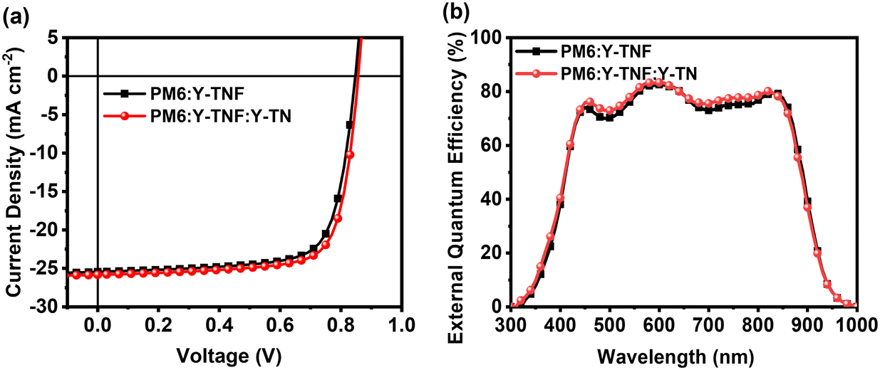 | ||
| Fig. 3 (a) J–V plots of the PM6:Y-TNF:Y-TN-based OSCs (1:1:0 and 1:1:0.1, w/w/w) with 0.25% DIO additive, and a TA treatment at 100 °C for 5 min under an illumination of AM 1.5 G, 100 mW cm−2, and (b) EQE curves of the corresponding OSCs. | ||
:1:0.1, w/w/w) with 0.25% DIO additive, and TA treatment at 100 °C for 5 min under the illumination of AM 1.5 G, 100 mW cm−2
To elucidate the factors contributing to the enhanced photovoltaic performance of the ternary device incorporating Y-TN, we conducted an investigation into exciton dissociation, charge transport, and charge collection within both the binary device (PM6:Y-TNF) and the ternary device (PM6:Y-TNF:Y-TN with D:A ratio of 1:1:0.1). Fig. 4a shows the photocurrent density (Jph) versus effective voltage (Veff) curves for binary and ternary devices, while the corresponding exciton dissociation (Pdiss) and charge collection (Pcoll) efficiencies are calculated. Jph is defined by the equation Jph = JL − JD, where JL represents the photocurrent density under illumination and JD denotes the photocurrent density in darkness. Veff is defined as Veff = V0 − Vb, where V0 is the voltage at which Jph reaches 0, and Vb is the applied bias voltage.60,61 As Veff increases gradually, Jph exhibits a positive correlation until reaching saturation. In this study, the saturation current density (Jsat) is designated as the value of Jph at Veff = 2.0 V. The exciton dissociation (Pdiss) and charge collection (Pcoll) are determined by the ratio of Jph/Jsat under short-circuit and maximum power conditions, respectively. The ternary device demonstrates Pdiss and Pcoll values of 97.70% and 86.02%, respectively, surpassing the binary device's respective values of 96.89% and 83.80%. This indicates that the incorporation of Y-TN significantly enhances the exciton dissociation and charge collection efficiency of the binary device.
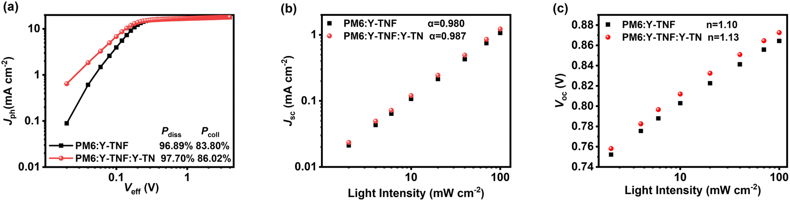 | ||
| Fig. 4 (a) Jph–Veff curves, (b) Jsc–Plight and (c) Voc–Plight of the binary device based on PM6:Y-TNF and the ternary device based on PM6:Y-TNF:Y-TN (1:1:0.1, w/w/w). | ||
The dependence of the Voc and Jsc on light intensity (Plight) was measured to evaluate the charge complexation behaviour of the corresponding devices. According to Jsc ∝ Pαlight, where α represents the degree of bimolecular complexation, the closer the value of α is to 1, the less bimolecular complexation of the corresponding device is indicated. As shown in Fig. 4b, the α value of the PM6:Y-TNF:Y-TN-based ternary device is 0.987, which is higher than that of the binary device of 0.980, indicating that the bimolecular recombination of the ternary device is inhibited. Voc ∝ (nkT/e)lnPlight, where k, T and e are the Boltzmann constant, absolute temperature and elementary charge, respectively, and n indicates whether the process is bimolecular recombination (n → 1) or trap-assisted recombination (n → 2). The slopes of Vocversus lnPlight are 1.13 and 1.10 kT/e for the ternary and binary devices, respectively (Fig. 4c), which indicates the suppressed bimolecular recombination in both the ternary and binary devices.
The photoinduced charge carrier extraction by linearly increasing voltage (Photo-CELIV) measurements was employed to investigate the carrier generation and transport behavior of the binary and ternary devices under operational conditions. Fig. 5a and Table S9 (ESI†) present the Photo-CELIV curves and data recorded for binary and ternary devices. The carrier mobility (μ) of the PM6:Y-TNF-based binary device and the PM6:Y-TNF:Y-TN-based ternary device are 1.97 × 10⁻⁴ and 2.05 × 10⁻⁴ cm2 V−1s−1, respectively. The higher carrier mobility of the ternary device suggests better charge transport. The transient photovoltage (TPV) and transient photocurrent (TPC) experiments were conducted to comprehend the charge transport and recombination characteristics of the binary and ternary devices, as shown in Fig. 5b and c. The TPV test (Fig. 5b) calculates the carrier lifetime (τ) using the formula V(t) = Voc + ΔV × exp(−t/τ). The carrier lifetimes (τ) of the binary and ternary devices are 0.62 and 0.87 μs, respectively, and the extended carrier lifetime indicates reduced charge recombination in the ternary device. In the TPC test (Fig. 5c), the device generates transient currents due to optical pulses. The more rapid transient current response of the ternary device compared to the binary device signifies that the ternary device has higher charge mobility and fewer traps. These results indicate the enhanced performance of the ternary device with the inclusion of Y-TN, which exhibits augmented charge transport, elevated exciton dissociation efficiency, and diminished carrier recombination compared to the PM6:Y-TNF-based binary device.
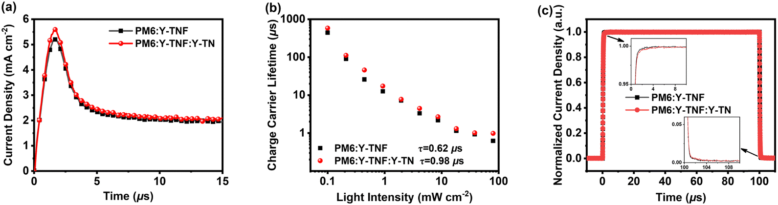 | ||
| Fig. 5 (a) Photo-CELIV curves, (b) carrier lifetime curves and (c) TPC results of the binary device based on PM6:Y-TNF and the ternary device based on PM6:Y-TNF:Y-TN (1:1:0.1, w/w/w). | ||
The AFM images of the active layer were analyzed to assess the quality of the corresponding devices. As depicted in Fig. 6(a) and (b), the root mean square (RMS) roughness values for the optimal blend films of PM6:Y-TNF and PM6:Y-TNF:Y-TN were 0.99 nm and 1.20 nm, respectively, indicating a uniform surface for both. The transmission electron microscopy (TEM) images further revealed that the active layer possessed an interpenetrating nanofibrous structure with appropriate phase separation morphology.
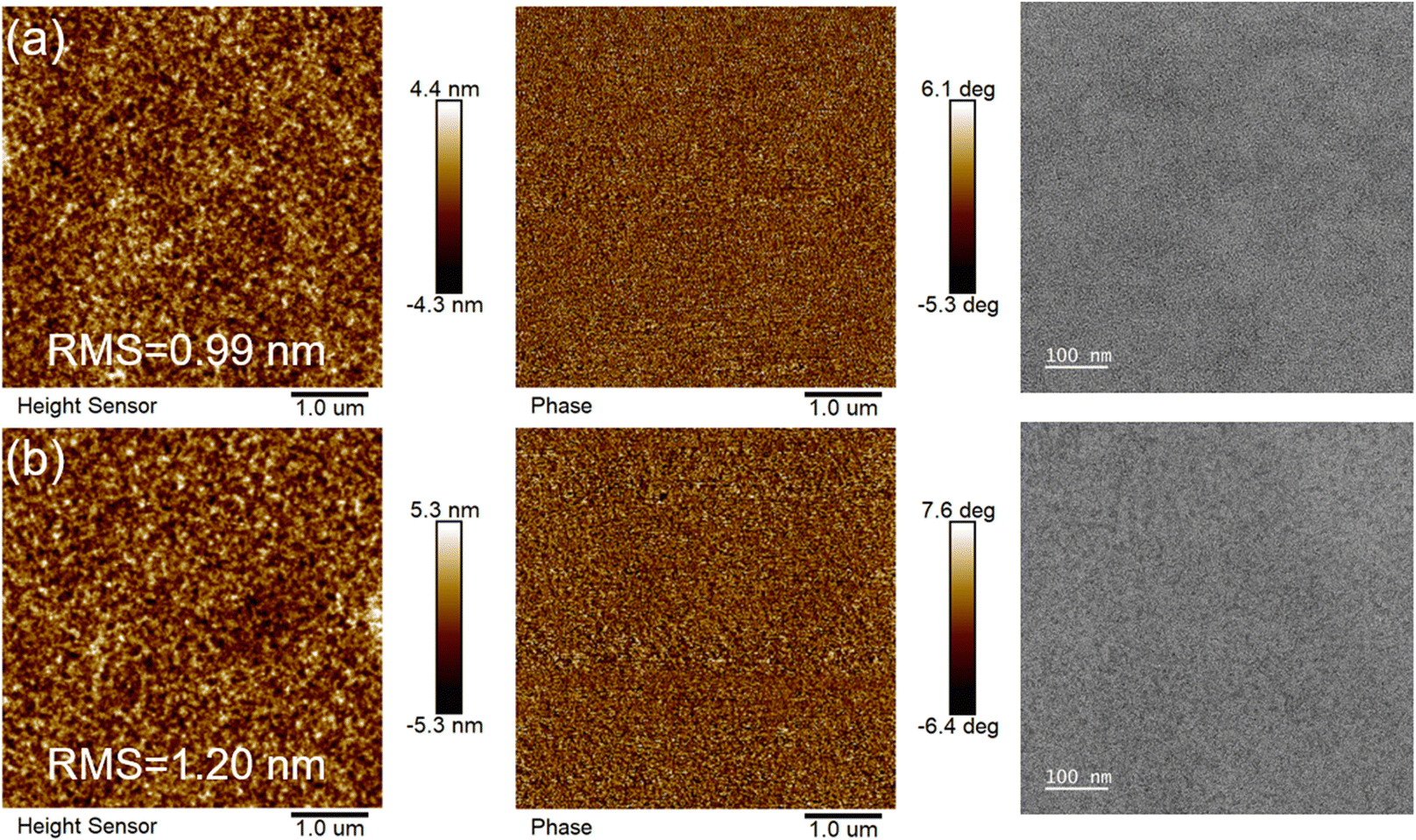 | ||
| Fig. 6 AFM (left-height image, middle-phase image) and TEM (right) images of optimal blend films of (a) PM6:Y-TNF and (b) PM6:Y-TNF:Y-TN. | ||
To elucidate the enhancements in device efficiency and stability, we conducted a morphological characterisation of the blended films. The GIWAXS results for the blend films are shown in Fig. 7, with the corresponding data summarized in Table S10 (ESI†). The film of PM6:Y-TNF exhibits a sharp (100) diffraction peak along the IP directions at qxy = 0.29 Å−1, indicative of alkyl chain packing with a d-spacing of 20.93 Å. Additionally, there is a distinct yet broad (010) π–π stacking peak along the OOP direction at qz =1.66 Å−1, corresponding to a d-spacing of 3.78 Å. The ternary blend film of PM6:Y-TNF:Y-TN also presents well-defined diffraction peaks along the IP direction at qz = 0.30 Å−1, with a reduced d-spacing of 20.26 Å, and pronounced π–π stacking peaks (010) at qz = 1.71 Å−1 with a π–π stacking distance of 3.67 Å. Both PM6:Y-TNF and PM6:Y-TNF:Y-TN demonstrate a preferred face-on stacking orientation relative to the substrate. Moreover, PM6:Y-TNF and PM6:Y-TNF:Y-TN display comparable crystalline coherence length (CCL) in the IP and OOP direction (Table S9, ESI†). These findings are consistent with the characterization results of carrier mobility and morphology.
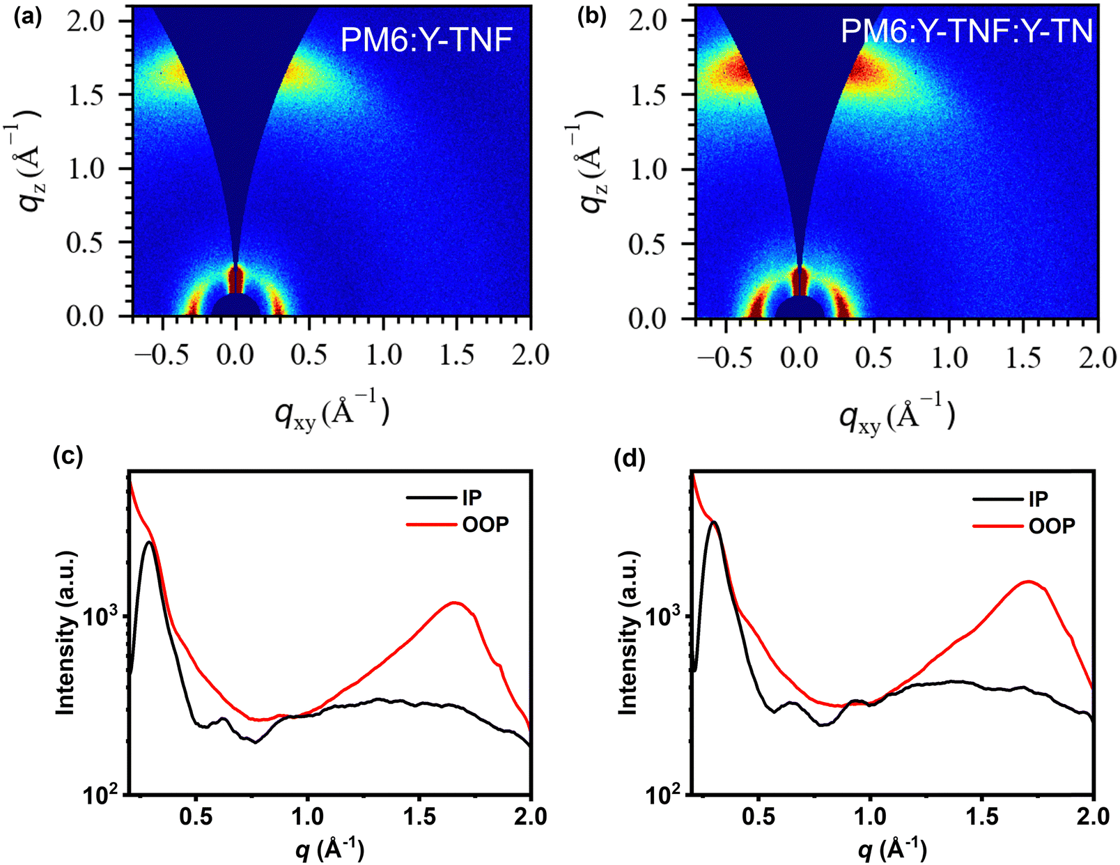 | ||
| Fig. 7 (a) The two-dimensional GIWAXS patterns of PM6:Y-TNF film, (b) the two-dimensional GIWAXS patterns of PM6:Y-TNF:Y-TN film, (c) the corresponding in-plane and out-of-plane profiles under PM6:Y-TNF film optimal conditions, and (d) the corresponding in-plane and out-of-plane profiles under PM6:Y-TNF:Y-TN film optimal conditions. | ||
3. Conclusion
Two small molecules, namely Y-TNF and Y-TN, were synthesized, based on an A–DA′D–A type molecular skeleton with fluorinated and non-fluorinated extended terminal groups. Y-TNF demonstrated a more suitable energy level, red-shifted absorption, and a narrow bandgap, leading to better photovoltaic performance compared to Y-TN. Incorporating non-fluorinated Y-TN as the third component into the PM6:Y-TNF-based OSC devices resulted in a higher PCE of 16.63%, with a high Voc of 0.857 V, a high Jsc of 25.84 mA cm−2, and a high FF of 75.10%. Non-fluorinated Y-TN effectively enhances the miscibility between the individual components of the fluorinated Y-TNF-based components, improves charge transfer efficiency and inhibits charge complexation behaviour. These results indicate that incorporating a similar acceptor material as a third component is an effective strategy to enhance the performance of OSCs.4. Experimental section
4.1. Synthesis of materials
PM6,62 Y-TNF and Y-TN55 were synthesized as reported in the literature, and the characterization results are listed in Fig. S1–S6 in the ESI.†4.2. Device fabrication method
Detailed descriptions are listed in the ESI.†Data availability
The authors confirm that the data supporting the findings of this study are available within the article and its ESI.†Conflicts of interest
There are no conflicts to declare.Acknowledgements
This work was supported by the National Natural Science Foundation of China (52173188), Zhongyuan University of Technology Discipline Strength Enhancement Program (GG202410), Program for Science & Technology Innovation Talents in Universities of Henan Province (20HASTIT030), the Training Plan of Young Backbone Teachers in Colleges and Universities of Henan Province (2019GGJS141) and Natural Science Foundation of Zhongyuan University of Technology (K2023MS008).References
- Y. Lin, J. Wang, Z.-G. Zhang, H. Bai, Y. Li, D. Zhu and X. Zhan, Adv. Mater., 2015, 27, 1170–1174 CrossRef CAS PubMed.
- B. Jia and X. Zhan, Sci. China Chem., 2020, 63, 1179–1181 CrossRef CAS.
- C. Yan, S. Barlow, Z. Wang, Y. He, K.-Y. Alex, R. M. Seth and X. Zhan, Nat. Rev. Mater., 2018, 3, 18003 CrossRef CAS.
- F. Meng, Y. Qin, Y. Zheng, Z. Zhao, Y. Sun, Y. Yang, K. Gao and D. Zhao, Angew. Chem., Int. Ed., 2023, 62, e202217173 CrossRef CAS PubMed.
- J. Wang, Y. Xie, K. Chen, H. Wu, J. M. Hodgkiss and X. Zhan, Nat. Rev. Phys., 2024, 6, 365–381 CrossRef CAS.
- Q. Wei, W. Liu, M. Leclerc, J. Yuan, H. Chen and Y. Zou, Sci. China Chem., 2020, 63, 1352–1366 CrossRef CAS.
- J. Ge, L. Xie, R. Peng and Z. Ge, Adv. Mater., 2022, 35, e2206566 CrossRef PubMed.
- H. Hu, S. Liu, J. Xu, R. Ma, Z. Peng, T. A. Dela Peña, Y. Cui, W. Liang, X. Zhou, S. Luo, H. Yu, M. Li, J. Wu, S. Chen, G. Li and Y. Chen, Angew. Chem., Int. Ed., 2024, 63, e202400086 CrossRef CAS PubMed.
- F. Liu, Y. Jiang, R. Xu, W. Su, S. Wang, Y. Zhang, K. Liu, S. Xu, W. Zhang, Y. Yi, W. Ma and X. Zhu, Angew. Chem., Int. Ed., 2024, 63, e202313791 CrossRef CAS PubMed.
- K. Liu, Y. Jiang, G. Ran, F. Liu, W. Zhang and X. Zhu, Joule, 2024, 8, 1–17 CrossRef.
- L. Wang, C. Chen, Y. Fu, C. Guo, D. Li, J. Cheng, W. Sun, Z. Gan, Y. Sun, B. Zhou, C. Liu, D. Liu, W. Li and T. Wang, Nat. Energy, 2024, 9, 208–218 CrossRef CAS.
- P. Murugan, T. Hu, X. Hu and Y. Chen, J. Mater. Chem. A, 2022, 10, 17968–17987 RSC.
- H. Chen, Y. Zou, H. Liang, T. He, X. Xu, Y. Zhang, Z. Ma, J. Wang, M. Zhang, Q. Li, C. Li, G. Long, X. Wan, Z. Yao and Y. Chen, Sci. China Chem., 2022, 65, 1362–1373 CrossRef CAS.
- S. Luo, C. Li, J. Zhang, X. Zou, H. Zhao, K. Ding, H. Huang, J. Song, J. Yi, H. Yu, K. S. Wong, G. Zhang, H. Ade, W. Ma, H. Hu, Y. Sun and H. Yan, Nat. Commun., 2023, 14, 6964 CrossRef CAS PubMed.
- W. Tang, Z. Ding, Y. Su, Q. Weng, Y. Zhang, R. Li, W. Huang, Z. Wang, Y. Wu, Y. Han, K. Zhao, Z. Yang, X. Wang and S. Liu, Adv. Funct. Mater., 2024, 34, 2312289 CrossRef CAS.
- H. Liang, X. Bi, H. Chen, T. He, Y. Lin, Y. Zhang, K. Ma, W. Feng, Z. Ma, G. Long, C. Li, B. Kan, H. Zhang, O. A. Rakitin, X. Wan, Z. Yao and Y. Chen, Nat. Commun., 2023, 14, 4707 CrossRef CAS PubMed.
- L. Wang, C. Chen, Y. Fu, C. Guo, D. Li, J. Cheng, W. Sun, Z. Gan, Y. Sun, B. Zhou, C. Liu, D. Liu, W. Li and T. Wang, Nat. Energy, 2024, 9, 208–218 CrossRef CAS.
- Q. Fan, R. Ma, Z. Bi, X. Liao, B. Wu, S. Zhang, W. Su, J. Fang, C. Zhao, C. Yan, K. Chen, Y. Li, C. Gao, G. Li and W. Ma, Adv. Funct. Mater., 2023, 33, 2211385 CrossRef CAS.
- T. Chen, S. Li, Y. Li, Z. Chen, H. Wu, Y. Lin, Y. Gao, M. Wang, G. Ding, J. Min, Z. Ma, H. Zhu, L. Zuo and H. Chen, Adv. Mater., 2023, 35, 2300400 CrossRef CAS PubMed.
- Q. Liu and K. Vandewal, Adv. Mater., 2023, 35, 2302452 CrossRef CAS PubMed.
- X. Gao, X. Ma, Z. Liu, J. Gao, Q. Qi, Y. Yu, Y. Gao, Z. Ma, L. Ye, J. Min, J. Wen, J. Gao, F. Zhang and Z. Liu, ACS Appl. Mater. Interfaces, 2022, 14, 23701–23708 CrossRef CAS PubMed.
- C. Guo, Y. Sun, L. Wang, C. Liu, C. Chen, J. Cheng, W. Xia, Z. Gan, J. Zhou, Z. Chen, J. Zhou, D. Liu, J. Guo, W. Li and T. Wang, Energy Environ. Sci., 2024, 17, 2492–2499 RSC.
- C. Liu, Y. Fu, J. Zhou, L. Wang, C. Guo, J. Cheng, W. Sun, C. Chen, J. Zhou, D. Liu, W. Li and T. Wang, Adv. Mater., 2024, 36, 2308608 CrossRef CAS PubMed.
- D. Li, N. Deng, Y. Fu, C. Guo, B. Zhou, L. Wang, J. Zhou, D. Liu, W. Li, K. Wang, Y. Sun and T. Wang, Adv. Mater., 2023, 35, 2208211 CrossRef CAS PubMed.
- P. Ding, D. Yang, S. Yang and Z. Ge, Chem. Soc. Rev., 2024, 53, 2350–2387 RSC.
- Q. Wei, J. Yuan, Y. Yi, C. Zhang and Y. Zou, Natl. Sci. Rev., 2021, 8, nwab121 CrossRef CAS PubMed.
- J. Yuan, Y. Zhang, L. Zhou, G. Zhang, H.-L. Yip, T.-K. Lau, X. Lu, C. Zhu, H. Peng, P. A. Johnson, M. Leclerc, Y. Cao, J. Ulanski, Y. Li and Y. Zou, Joule, 2019, 3, 1140–1151 CrossRef CAS.
- Y. Shi, L. Zhu, Y. Yan, M. Xie, G. Liang, J. Qiao, J. Zhang, X. Hao, K. Lu and Z. Wei, Adv. Energy Mater., 2023, 13, 2300458 CrossRef CAS.
- T. Zhang, C. An, Y. Xu, P. Bi, Z. Chen, J. Wang, N. Yang, Y. Yang, B. Xu, H. Yao, X. Hao, S. Zhang and J. Hou, Adv. Mater., 2022, 34, 2207009 CrossRef CAS PubMed.
- M. Xie, Y. Shi, L. Zhu, J. Zhang, Q. Cheng, H. Zhang, Y. Yan, M. Zhu, H. Zhou, K. Lu and Z. Wei, Energy Environ. Sci., 2023, 16, 3543–3551 RSC.
- L. Wang, Q. An, L. Yan, H.-R. Bai, M. Jiang, A. Mahmood, C. Yang, H. Zhi and J.-L. Wang, Energy Environ. Sci., 2022, 15, 320–333 RSC.
- Y. Chen, R. Ma, T. Liu, Y. Xiao, H. K. Kim, J. Zhang, C. Ma, H. Sun, F. Bai, X. Guo, K. S. Wong, X. Lu and H. Yan, Adv. Energy Mater., 2021, 11, 202003777 Search PubMed.
- A. Shang, S. Luo, J. Zhang, H. Zhao, X. Xia, M. Pan, C. Li, Y. Chen, J. Yi, X. Lu, W. Ma, H. Yan and H. Hu, Sci. China Chem., 2022, 65, 1758–1766 CrossRef CAS.
- Z. Luo, Y. Gao, H. Lai, Y. Li, Z. Wu, Z. Chen, R. Sun, J. Ren, C. E. Zhang, F. He, H. Woo, J. Min and C. Yang, Energy Environ. Sci., 2022, 15, 4601–4611 RSC.
- T. A. Dela Peña, R. Ma, Z. Xing, Q. Wei, J. I. Khan, R. M. Young, Y. Hai, S. A. Garcia, X. Zou, Z. Jin, F. L. Ng, K. L. Yeung, D. F. Swearer, M. R. Wasielewski, J. Wang, H. Cha, H. Yan, K. S. Wong, G. Li, M. Li and J. Wu, Energy Environ. Sci., 2023, 16, 3416–3429 RSC.
- Z. Jia, Q. Ma, Z. Chen, L. Meng, N. Jain, I. Angunawela, S. Qin, X. Kong, X. Li, Y. M. Yang, H. Zhu, H. Ade, F. Gao and Y. Li, Nat. Commun., 2023, 14, 1236 CrossRef CAS PubMed.
- F. Bai, J. Zhang, A. Zeng, H. Zhao, K. Duan, H. Yu, K. Cheng, G. Chai, Y. Chen, J. Liang, W. Ma and H. Yan, Joule, 2021, 5, 1231–1245 CrossRef CAS.
- Y. Zeng, D. Li, Z. Xiao, H. Wu, Z. Chen, T. Hao, S. Xiong, Z. Ma, H. Zhu, L. Ding and Q. Bao, Adv. Energy Mater., 2021, 11, 2101338 CrossRef CAS.
- Y. Wei, Y. Cai, X. Gu, G. Yao, Z. Fu, Y. Zhu, J. Yang, J. Dai, J. Zhang, X. Zhang, X. Hao, G. Lu, Z. Tang, Q. Peng, C. Zhang and H. Huang, Adv. Mater., 2023, 36, 2304225 CrossRef PubMed.
- Q. Fan, R. Ma, J. Yang, J. Gao, H. Bai, W. Su, Z. Liang, Y. Wu, L. Tang, Y. Li, Q. Wu, K. Wang, L. Yan, R. Zhang, F. Gao, G. Li and W. Ma, Angew. Chem., Int. Ed., 2023, 62, e202308307 CrossRef CAS PubMed.
- H. Bai, Q. An, M. Jiang, H. S. Ryu, J. Yang, X.-J. Zhou, H.-F. Zhi, C. Yang, X. Li, H. Y. Woo and J.-L. Wang, Adv. Funct. Mater., 2022, 32, 2200807 CrossRef CAS.
- Y. Wu, H. Yang, Y. Zou, Y. Dong, C. Cui and Y. Li, Sol. RRL, 2018, 2, 1800060 CrossRef.
- Z. Bi, H. B. Naveed, H. Wu, C. Zhang, X. Zhou, J. Wang, M. Wang, X. Wu, Q. Zhu, K. Zhou, K. Chen, C. Wang, Z. Tang and W. Ma, Adv. Energy Mater., 2022, 12, 2103735 CrossRef CAS.
- N. Gasparini, A. Salleo, I. McCulloch and D. Baran, Nat. Rev. Mater., 2019, 4, 229–242 CrossRef.
- P. Bi, J. Wang, Y. Cui, J. Zhang, T. Zhang, Z. Chen, J. Qiao, J. Dai, S. Zhang, X. Hao, Z. Wei and J. Hou, Adv. Mater., 2023, 35, 2210865 CrossRef CAS PubMed.
- W. Huang, P. Cheng, Y. M. Yang, G. Li and Y. Yang, Adv. Mater., 2018, 30, 1705706 CrossRef PubMed.
- D. Luo, Z. Jiang, W. L. Tan, L. Zhang, L. Li, C. Shan, C. R. McNeill, P. Sonar, B. Xu and A. K. K. Kyaw, Adv. Energy Mater., 2022, 13, 202203402 Search PubMed.
- M. Li, Z. Peng, K. Xian, W. Zhao, C. Liu, Y. Chen, C. Cui and L. Ye, J. Mater. Chem. A, 2023, 11, 5606–5614 RSC.
- Z. Chen, J. Zhu, D. Yang, W. Song, J. Shi, J. Ge, Y. Guo, X. Tong, F. Chen and Z. Ge, Energy Environ. Sci., 2023, 16, 3119–3127 RSC.
- H. B. Naveed and W. Ma, Joule, 2018, 2, 621–641 CrossRef CAS.
- D. Li, L. Wang, C. Guo, Y. Liu, B. Zhou, Y. Fu, J. Zhou, D. Liu, W. Li and T. Wang, ACS Mater. Lett., 2023, 5, 2065–2073 CrossRef CAS.
- L. Xie, A. Lan, Q. Gu, S. Yang, W. Song, J. Ge, R. Zhou, Z. Chen, J. Zhang, X. Zhang, D. Yang, B. Tang, T. Wu and Z. Ge, ACS Energy Lett., 2022, 8, 361–371 CrossRef.
- T. Duan, W. Feng, Y. Li, Z. Li, Z. Zhang, H. Liang, H. Chen, C. Zhong, S. Jeong, C. Yang, S. Chen, S. Lu, O. A. Rakitin, C. Li, X. Wan, B. Kan and Y. Chen, Angew. Chem., Int. Ed., 2023, 62, e202303832 Search PubMed.
- C. He, Q. Shen, B. Wu, Y. Gao, S. Li, J. Min, W. Ma, L. Zuo and H. Chen, Adv. Energy Mater., 2023, 13, 2204154 CrossRef CAS.
- G. Li, X. Zhang, L. O. Jones, J. M. Alzola, S. Mukherjee, L. W. Feng, W. Zhu, C. L. Stern, W. Huang, J. Yu, V. K. Sangwan, D. M. DeLongchamp, K. L. Kohlstedt, M. R. Wasielewski, M. C. Hersam, G. C. Schatz, A. Facchetti and T. J. Marks, J. Am. Chem. Soc., 2021, 143, 6123–6139 CrossRef CAS PubMed.
- Q. Sun, H. Wang, C. Yang and Y. Li, J. Mater. Chem., 2003, 13, 800–806 RSC.
- Y. Zhang, H. Yao, S. Zhang, Y. Qin, J. Zhang, L. Yang, W. Li, Z. Wei, F. Gao and J. Hou, Sci. China Chem., 2018, 61, 1328–1337 CrossRef CAS.
- K. Jiang, J. Zhang, C. Zhong, F. R. Lin, F. Qi, Q. Li, Z. Peng, W. Kaminsky, S.-H. Jang, J. Yu, X. Deng, H. Hu, D. Shen, F. Gao, H. Ade, M. Xiao, C. Zhang and A. K. Y. Jen, Nat. Energy, 2022, 7, 1076–1086 CrossRef.
- J. Chen, D. Li, M. Su, Y. Xiao, H. Chen, M. Lin, X. Qiao, L. Dang, X. C. Huang, F. He and Q. Wu, Angew. Chem., Int. Ed., 2023, 62, e202215930 CrossRef CAS PubMed.
- J. L. Wu, F. C. Chen, Y. S. Hsiao, F. C. Chien, P. Chen, C. H. Kuo, M. H. Huang and C. S. Hsu, ACS Nano, 2011, 5, 959–967 CrossRef CAS PubMed.
- Y. Gong, T. Zou, X. Li, H. Zhuo, S. Qin, G. Sun, L. Meng and Y. Li, Sci. China Chem., 2023, 66, 2912–2920 CrossRef CAS.
- M. Zhang, X. Guo, W. Ma, H. Ade and J. Hou, Adv. Mater., 2015, 27, 4655–4660 CrossRef CAS PubMed.
Footnote |
| † Electronic supplementary information (ESI) available. See DOI: https://doi.org/10.1039/d4ya00304g |
| This journal is © The Royal Society of Chemistry 2024 |