
 Open Access Article
 This Open Access Article is licensed under a
 Creative Commons Attribution 3.0 Unported Licence
Spin-crossover tuning of the luminescence in 2D Hofmann-type compounds in bulk and exfoliated flakes†
Víctor
García-López‡
 ,
Francisco
Marques-Moros‡
,
José
Troya
,
Josep
Canet-Ferrer
*,
Miguel
Clemente-León
* and
Eugenio
Coronado
,
Francisco
Marques-Moros‡
,
José
Troya
,
Josep
Canet-Ferrer
*,
Miguel
Clemente-León
* and
Eugenio
Coronado
Instituto de Ciencia Molecular (ICMol), Universitat de València, C/Catedrático José Beltrán 2, Paterna 46980, Spain. E-mail: miguel.clemente@uv.es; jose.canet-ferrer@uv.es; Fax: +34 963543273; Tel: +34 963544419
First published on 29th November 2023
Abstract
The synthesis, structure and magnetic and optical characterization of a new, [FeII(furtrz)2(Pt(CN)4)]·4H2O (1), flexible 2D Hofmann-type material is reported together with the optical characterization of the already reported, [Fe3II(saltrz)6(Pt(CN)4)3]·8H2O (2). Both compounds exhibit in the bulk multi-step thermal SCO. The temperature dependence of the luminescence properties of 2, reported for the first time in this work, show a clear interplay between SCO and luminescence, while in the case of 1, resonant emission shows only a subtle change around the SCO temperature. Thanks to their layered structure and weak interlayer interactions, it has been possible to obtain flakes of micrometric lateral sizes and thicknesses of a few nm of the two compounds using the well-known Scotch tape method. The effect of the miniaturization in the SCO properties and luminescence has been studied by Raman spectroscopy and luminescence. In the case of 2, the abrupt SCO is lost in the exfoliated flakes, while in 1 a clear spin transition is still observed in a plethora of flakes with thicknesses ranging from a few nanometers up to hundreds.
Introduction
The interplay between spin-crossover (SCO) and fluorescence is the focus of considerable interest1 since the control of the spin state could be used to modulate the luminescence signal and lead to applications such as thermometry,2 magneto-optical switches,3 or multi-sensors.4 Moreover, luminescence can be used as an internal proof to follow the spin transition of the SCO centers in a material. Previous reports of multifunctional luminescent SCO compounds are based on discrete complexes5–8 or coordination polymers (CPs).9–15A remarkable family of SCO CPs are Hofmann-like compounds of formula [FeII(L)xM(CN)y] constructed by the equatorial coordination of tetracyanometallates ([MII(CN)4]2− with M = Pt, Pd or Ni) and the axial coordination of aromatic N-donor ligands (L), where L can be unidentate or bidentate bridging ligands to build 2D or 3D coordination networks, respectively. This family of compounds exhibits cooperative SCO, which can be modulated by a rich host–guest chemistry.16,17 There are many examples of multifunctional Hofmann-like compounds thanks to the possibility of using different functional L ligands and guest molecules maintaining the structure and interesting SCO properties. Among them, luminescent Hofmann-like CPs have been prepared following two strategies: (i) the use of a fluorophore as pillaring ligand and (ii) the inclusion of a fluorescent guest into the cavities of the network.13–15,17–19
This family of compounds has demonstrated to be an excellent platform to investigate the SCO properties at the nano-scale as they can be miniaturized as thin films or nanoparticles maintaining the SCO properties.20 Since 2D Hofmann-like compounds display a layered structure with strong intralayer covalent bonding and weaker van der Waals interactions between the layers, an interesting possibility is the exfoliation into individual nanosheets that have found in other 2D materials a great variety of applications in electronics, gas storage or separation, catalysis or high-performance sensing.21,22 Previous attempts to exfoliate 2D Hofmann-like compounds by mechanical or solvent-mediated exfoliation methods led to low-quality nanosheets with a thickness of a few nm in the case of the liquid exfoliation method23,24 or to larger but thicker flakes (more than 300 nm thick) in that of mechanical exfoliation.25
In this work, we have explored the miniaturization by a mechanical exfoliation of luminescent SCO 2D Hofmann-like compounds. Two 2D Hofmann like compounds containing flexible ligands to minimize interlayer interactions have been prepared and characterized: the new compound [Fe(furtrz)2Pt(CN)4]·4H2O (furtrz = furanylidene-4H-1,2,4-triazol-4-amine) (1) and [Fe3II(saltrz)6(Pt(CN)4)3]·8H2O (saltrz = (E)-2-(((4H-1,2,4-triazol-4-yl)imino)methyl)phenol) (2) reported by S. Neville et al. in 2017.26 The later has been chosen due to previous reports of a dimer based on the same ligand with formula [Fe2(saltrz)5(NCS)4]·4MeOH by Y. Garcia et al. in 2011 showing an interplay between luminescent and SCO properties.5 Thanks to the layered structure of 1 and 2, it has been possible to obtain flakes of micrometric lateral sizes and thicknesses of a few nm using the well-known Scotch tape method. The interplay between SCO and luminescence in the bulk compounds has been studied together with the effect of the miniaturization in both properties.
Results and discussion
Synthesis
1 and 2 were synthesized by slow diffusion of stoichiometric amounts of Fe(ClO4)2·xH2O and furtrz or saltrz in a water/ethanol mixture on top of K2[Pt(CN)4] in water (see Experimental Section for more details). Powder X-ray diffraction (PXRD) pattern of 2 is consistent with the simulated one from the structure reported in the literature (see Fig. S1, ESI†). The structure of 1 was successfully determined by single crystal diffraction. Elemental analysis of 1 confirms the loss of one water molecule found in the crystal structure (see Experimental Section). The Zn reference compounds of formulas [Zn(furtrz)2Pt(CN)4]·EtOH·H2O (1·Zn) and [Zn3(saltrz)6(Pt(CN)4)3]·8H2O (2·Zn) were prepared in an analogous way as that of 1 and 2, respectively. The structures were solved by single crystal X-ray diffraction (see Table S1 and Fig. S2 and associated text in the ESI†).Structure
Single crystal X-ray structure analysis of 1 was performed at 120 K (100% low-spin, LS, state), 204 K (mixed spin state) and 240 K (100% high-spin, HS, state) (see Table S1, ESI†). All of them are isostructural and belong to the Pnma space group. The asymmetric unit contains crystallographically independent Fe, Pt and two furtrz with occupancies of 0.5 plus two CN ligands and disordered water molecules. It presents the typical structure of 2D Hofmann materials formed by layers of Fe2+ centers connected to four equivalent square planar N-donor [Pt(CN)4]2− in the equatorial positions and to two N from triazole of two furtrz ligands in the axial positions completing the octahedral coordination. Thus, 2D undulating layers of composition Fe[Pt(CN)4]n are generated along the ab plane with furtrz ligands protruding above and below the layer (see Fig. 1). The inter-digitation of the furtz ligands allows an efficient packing of the layers with enough space to host solvent water molecules, giving an overall formula of [Fe(furtrz)2[Pt(CN)4]]·4H2O. Similar structures have been obtained with other monodentate triazole derivatives as in compound [Fe(thtrz)2Pd(CN)4]·EtOH·H2O (thtrz = N-thiophenyl-idene-4H-1,2,4-triazol-4-amine).27 Due to the undulation of the framework, furtz ligands coming from different layers assemble in pairs with neighboring furtz along the b axis with several weak interactions. The voids are occupied at 120 K by four crystallographically independent disordered water molecules forming hydrogen bonds and giving rise to a pseudo 1D chain along the b axis. The hosted water molecules also have hydrogen bonds with the non-bonding N of the triazole. At higher temperatures, the disorder of these water molecules could not be modelled satisfactorily. It was removed from the electron density map using the OLEX solvent mask command.28 Two voids of 206.0 Å3 at 204 K and 226.0 Å3 at 240 K were found in the unit cell of the crystals occupied by approximately 16 water molecules, giving a void volume of 16.6% at 204 K and 17.4% at 240 K.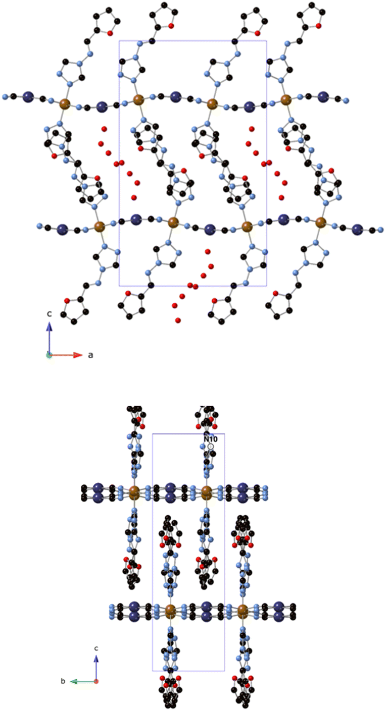 | ||
| Fig. 1 ac (top) and bc (bottom) plane projections of 1 (C (black), N (blue), O (red), Fe (orange), Pt (dark blue)). Only one of the two possible configurations are shown. Hydrogen atoms have been omitted for clarity. | ||
Fe–N bond lengths range from 2.09(3) to 2.16(4) Å at 240 K (average Fe–N bond length of 2.13(2) Å), in agreement with a HS state, and from 1.925(8) to 1.983(12) Å at 120 K (average Fe–N bond length of 1.938(12) Å), in agreement with a LS state. This is consistent with the complete thermal SCO observed from magnetic measurements in the same range of temperatures (see below). Finally, Fe–N bond lengths from 1.993(11) to 2.055(15) at 204 K (average Fe–N bond length of 2.016(16) Å) suggest an intermediate spin state.
PXRD measurements of 1 were performed at 280 K, 240 K, 200 K and 160 K in contact with the mother liquor. The most remarkable change is the shift to higher 2θ values of the peaks between 2θ = 14 and 21° upon decreasing in temperature. The position of the peaks changes noticeably comparing the mostly HS phases (280 K and 240 K), with the phase where the LS state is predominant (160 K). This is confirmed by the pattern measured at 200 K of the intermediate state which shows a peak intermediate to the HS and LS ones, in good agreement with the magnetic properties (see below). These PXRD patterns are consistent with the simulated patterns from the structures solved by single crystal X-ray diffraction (see Fig. S3, ESI†).
Magnetic properties
The thermal dependence of the product of the molar magnetic susceptibility with temperature (χMT) of 1 measured in contact with the mother liquor is shown in Fig. 2. In the cooling mode, χMT value remains constant at ca. 3.7 cm3 K·mol−1 from 300 to 210 K, which is the expected value for a Fe(II) HS. At lower temperatures, it shows an abrupt decrease in two steps. In the first one, χMT decreases from 3.5 cm3 K mol−1 at 210 K to 2.0 emu K mol−1 at 203 K, which represents the conversion of 1/2 of the Fe(II) sites from the HS to the LS. This is followed by a plateau from which a gradual decrease to 1.8 cm3 K mol−1 at 190 K takes place. At lower temperatures, there is a second abrupt decrease to reach values close to 0 cm3 K mol−1 at 183 K corresponding to a complete spin conversion. In the warming mode, the same two-step spin transition is maintained with small hysteresis loops in each step (Step 1: T1/2 ↓ ↑: 205, 214 K; Step 2: T1/2 ↓ ↑: 185, 198 K). The more marked two step-like spin transition in [Fe(thtrz)2Pd(CN)4]·EtOH·H2O, which presents a similar structure to that of 1, has been attributed to the negative cooperative impact imparted by the hydrogen-bonding network interconnecting the ligands of the two crystallographically independent Fe ions.27 A similar effect could be present in 1 due to the hydrogen bonds between triazole and water molecules placed between the ligands, although with only one type of iron. In agreement with this, the magnetic behaviour of the freshly filtered sample of 1 is shown in Fig. S4 (ESI†). The partial dehydration causes a partial loss of the step-like character of the spin transition with a decrease of the thermal hysteresis and a higher HS content in the plateau (see Fig. S4 and associated text in the ESI†). Illumination of a polycrystalline sample at 10 K with 573 and 632 nm did not give rise to an increase in the magnetic response so Light-Induced Excited Spin-State Trapping (LIESST) effect was not detected.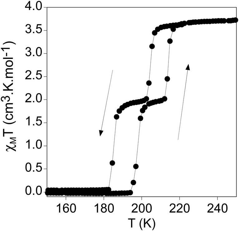 | ||
| Fig. 2 χ M T vs. temperature of 1 in contact with the mother liquor. | ||
Impact of the SCO transition on the optical properties in bulk
In this section, the impact of the SCO transition on the optical properties of both 1 and 2 materials is studied by means of photoluminescence (PL) and Raman. Then, the results are also compared to Zn references of both materials. In this way, the PL spectra of bulk crystals are acquired at different temperatures. Thus, the PL emission differences between the LS (120 K) and the HS (210 K) phases of 1, 2, and 1·Zn are shown in Fig. 3.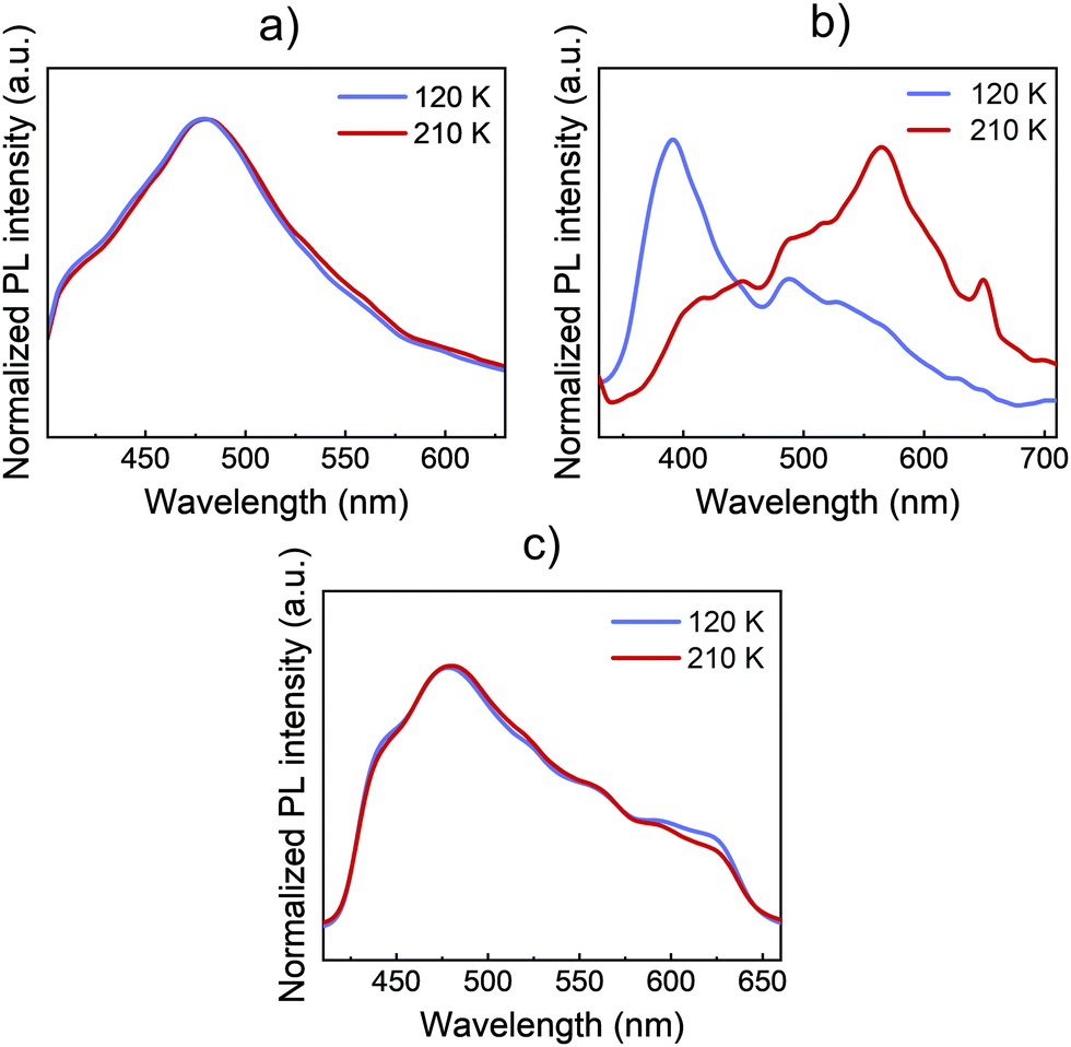 | ||
| Fig. 3 PL spectra of bulk crystals at representative temperatures in the LS and HS states of (a) 1, (b) 2, and (c) 1·Zn. Blue spectra correspond to the LS at 120 K and red spectra correspond to the HS at 210 K. Spectra have been normalized for the sake of an easier visual comparison. | ||
The bulk crystals of every material were placed on top of a silicon substrate. Then, the substrate with the sample was placed on the cold finger of a closed-cycle cryostat for the study of the PL and the Raman signal. Both compounds 1 and 2 present an intense and broad PL emission around 500 nm when exciting the bulk crystals with UV light at 325 nm. In the case of 1, the PL spectrum presents a uniform shape centred at 480 nm. Like 1·Zn, the PL emission remains nearly constant across the SCO transition temperatures, see Fig. 3a. On the contrary, in the case of 2 (see Fig. 3b), the spectral shape of the emission undergoes an abrupt change at the transition temperature (∼150 K). Here, the PL emission that dominates the spectra at 400 nm in the LS phase quenches, while the emission at lower energies, around 560 nm enhances. Thus, the shape of the PL emission is highly altered due to the SCO transition. These PL results are similar to the previous reported PL of a Fe(II) complex of the same ligand by Garcia et. al.5 On the contrary, the isostructural Zn references 1·Zn and 2·Zn do not show any noticeable change across the temperature sweep see Fig. 3c and Fig. S5 (ESI†). This further confirms that the changes in PL with temperature of 2 are directly related with spin transition. The whole temperature ramps are available in Fig. S5 (ESI†). In addition, we plotted the dependence of integrated PL intensity on the temperature for the complex 2, see Fig. S6 (ESI†). These results support that the abrupt PL changes in both bands of the spectra come from the SCO at ∼150 K, in agreement with the results reported by Garcia et. al.5
Under resonant excitation with a green 532 nm Nd:YAG laser light, the samples have been found to also present PL emission. Here, the temperature-dependent emission of 1 is again studied in order to find any optical signature of the SCO on the PL, see Fig. 4. In this way, the PL of 1 under resonant excitation is composed of a broad band centred at ∼650 nm at low temperatures in the LS state. As the temperature is increased near the transition temperature (above 170 K) there is a blue shift of the emission, where the maximum of the PL band is shifted to a lower wavelength. In addition, a higher energy shoulder can also be noticed at 560 nm in the HS. Thus, when exciting the bulk crystals of 1 with resonant excitation, due to the SCO, the PL emission shifts and slightly changes its spectral shape. However, although this shift is reproducible it is small compared to the overall width of the PL band and could be within the experimental error. For this reason, the impact of the SCO on the optical properties is further validated through Raman measurements.
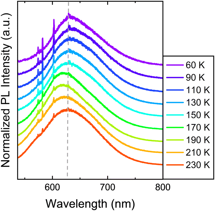 | ||
| Fig. 4 Temperature-dependent PL spectra of 1 by using a resonant 532 nm light excitation from a Nd:YAG laser. A dashed grey line has been added for reference to the eye. Notice that the spikes around 600 nm come from the Raman scattering of the sample. | ||
In this way, we investigated the experimental signatures of Raman spectroscopy for the same samples by irradiating them with the same 532 nm light from the second harmonic of a Nd:YAG laser, see Fig. 5. Here, we focus on the CN vibrations of the three materials nearby 2200 cm−1, as we found that these vibrations are the most affected by the SCO transition. In this way, as shown in Fig. 5, the CN vibrations in these materials provide a useful footprint to track the SCO.
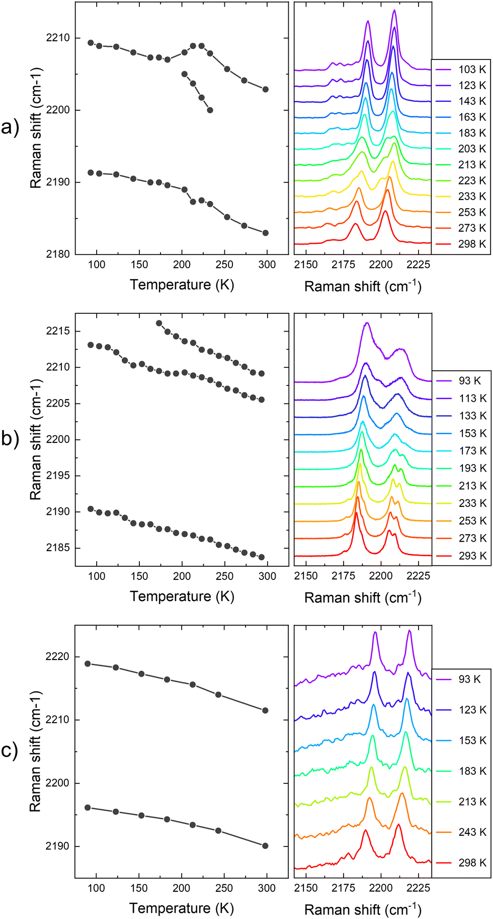 | ||
| Fig. 5 Raman shift of the CN vibration with the temperature of (a) 1 (b) 2, and (c) 1·Zn bulk crystal samples. The plot at the left represents the central frequency of the identified Raman vibrational bands. The y-axis of the Raman spectra at the right accounts for the intensity in arbitrary units. | ||
First, for the sample of 1, the Raman spectra consist of two main vibrational bands occurring at 2184 and 2205 cm−1 at 273 K, and at 2191 and 2209 cm−1 at 93 K, see Fig. 5a. A similar trend has been reported in the literature for the LS and HS forms of Fe(pz)[Pt(CN)4]·2H2O (pz = pyrazine).29 As the temperature increases from low temperatures, the CN vibrations shift to lower frequencies, due to a decrease in bond force constants due to thermal expansion and increased anharmonicity. In this way, the first peak shifts from 2191 cm−1 at 92 K to 2184 cm−1 at 273 K. The higher vibrational mode shifts from 2209 to 2205 cm−1 for the same temperature range. Importantly, the trend on the shift is broken in the temperature range of the SCO (∼200 K). Here, the higher frequency Raman mode splits in two different peaks. For example, at 200 K the split peaks are observed at 2189 and 2205 cm−1. However, at higher temperatures above 230 K, the splitting is lost and cannot be tracked. In addition to the splitting, the shift of the higher frequency peak does not follow a homogeneous trend in this temperature range. Other effects, such as relative intensity changes or splitting of Raman vibrations, have been also observed for other vibrational modes during the SCO temperature range, see Fig. S7 (ESI†). For example, a similar splitting effect is observed in the vibrational Raman mode at 1610 cm−1, which takes place at ∼200 K and it is maintained up to room temperature. Finally, we highlight the emission of vibrational modes at 2165 cm−1. Although the emission is low and is hindered by the high emission of the CN vibrations, a splitting of this peak also takes place at 200 K, again coinciding with the SCO.
Second, for the sample of 2, a similar behaviour with the temperature for the CN vibrations is tracked, see Fig. 5b. In this case, the lower frequency band matches the emission from the sample of 1 at 2184 cm−1 at 273 K, but the higher frequency band is split at this temperature. Similarly to the sample of 1, the higher frequency vibrational band is split at high temperatures coinciding with the HS state, and an additional band can be tracked at 2210 cm−1 above the transition temperature (∼150 K).26 In this way, as the temperature decreases, this second split band is apparently lost below 150 K, matching the SCO transition temperature of this compound. This splitting at high temperatures could be explained by the two unique [Fe{Pt(CN)4}] units contained in the crystal structure of compound 2.26 Regarding the Raman shift dependence with the temperature, the lower vibrational CN band shifts to 2191 cm−1 at 92 K, matching the shift of this band on the sample of 1. In addition, the shift of the higher vibrational mode goes from 2206 cm−1 to 2209 cm−1, which is also a similar shift compared to the same band on compound 1.
In Fig. 5c, we also display the Raman emission dependence with the temperature of 1·Zn. Here, the two main CN vibrational modes are tracked at 2196 and 2219 cm−1 at 93 K, which are at higher frequencies compared to the previous measurements for 1 and 2 materials. The bands shift homogeneously to lower frequencies as the temperature increases, until 2188 and 2212 cm−1 at room temperature. In this way, there is not any noticeable effect on these vibrations with the temperature, as expected for a reference sample not undergoing spin transition. This result further validates the correlation between the observed changes in the PL and Raman with the SCO of 1 and 2.
In the next sections, we study how the effect of the miniaturization of 1 and 2 bulk crystals into flakes (by mechanical exfoliation) affects the SCO properties and their optical response in these materials.
Exfoliation
The layered structures gave us the opportunity to explore the exfoliation of the two materials with the well-known Scotch tape methodology. This conventional approach, usually employed for graphene and other 2D materials, has been barely used in CPs due to the fragile nature of the crystals,30 however, thanks to the versatility provided by the molecular composition of the CPs, it is feasible to obtain compounds robust enough to be exfoliated.31 The advantage of this dry method over liquid exfoliation is the potential to achieve thin layers with high crystallinity and larger lateral sizes.Bulk crystals of 1 and 2 were exfoliated using a plastic tape (Ultron Systems) and deposited onto a 285 nm of thermally grown SiO2 substrate. As a result, a plethora of flakes with well-defined rectangular shapes (lateral dimensions of >1 μm) and different thicknesses (ranging from a few nanometers up to hundreds) were obtained, as can be clearly seen by optical and atomic force (AFM) microscopies (see Fig. 6 and Fig. S8–S10, ESI†). This contrasts with the low-quality nanosheets obtained in analogue compounds by liquid exfoliation23 and to the thicker flakes obtained from a less flexible Hofmann-like CP.25 The chemical composition and integrity of the exfoliated flakes were confirmed by Raman spectroscopy studies on specimens of different thicknesses (see Fig. 7 and Fig. S11, ESI†).
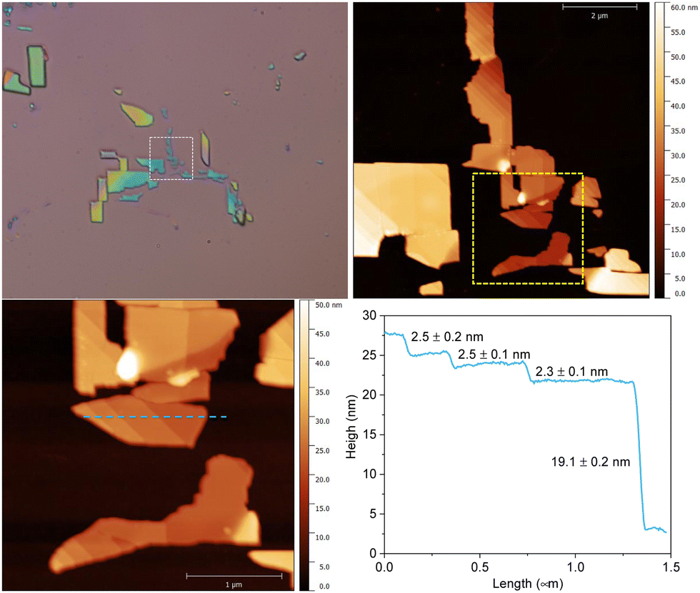 | ||
| Fig. 6 Optical and AFM images of the exfoliation of 1. General optical image (top left). AFM image (top right) of the selected region in dashed white in the top right image with its corresponding zoom (bottom left; marked in yellow in top right) and its height profile (bottom right; marked in dashed blue in the bottom left image) | ||
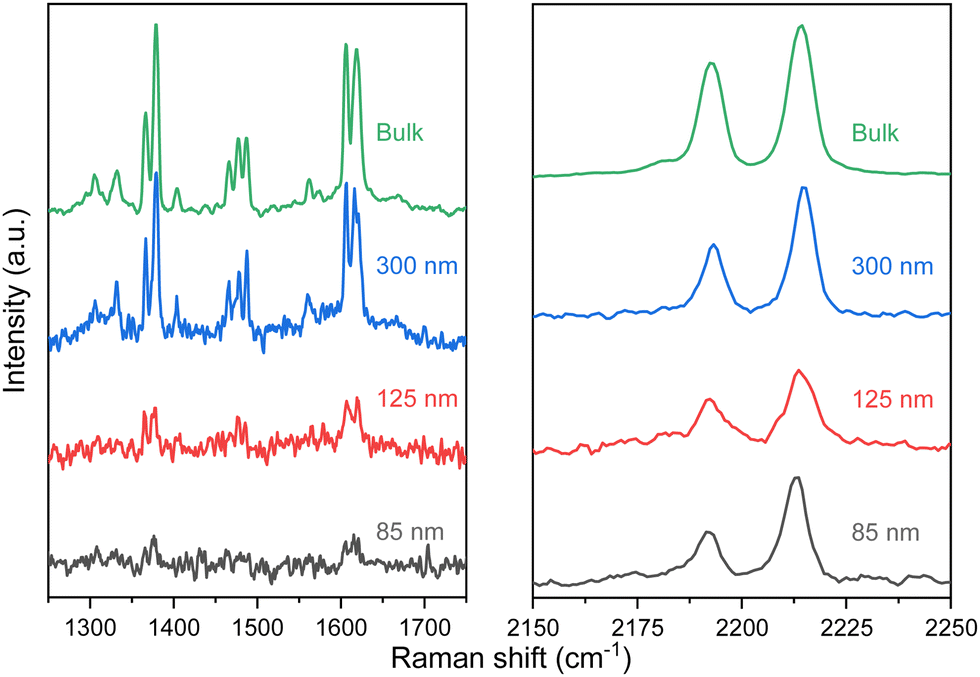 | ||
| Fig. 7 Raman spectra of selected flakes of 1 with height from 300 to 85 nm in the 1250–1800 and 2150–2250 cm−1 range of interest at room temperature. | ||
Optical signature of the SCO transition in flakes
The optical response of 1 and 2 exfoliated crystals was measured by means of PL and Raman at different temperatures across the SCO transition of the bulk. To carry out these measurements, we used the same 532 nm light excitation from the second harmonic of a Nd:YAG laser used in the bulk crystals, with an irradiation power of 0.4 mW on the sample, which is inside the linear optical response range of the samples (see Fig. S12, ESI†). Note that the spot size at the sample is in the range of hundreds of μm, in order to average the signal of diverse flakes on the substrate and avoid mechanical deviations from any cryostat vibrations or temperature dilatation of the substrate or the cold finger of the cryostat. Thus, differences between the resonant PL emission of the LS (110 K) and HS (220 K) phases for 1 in the bulk together with that of the flakes at the same temperatures are displayed in Fig. 8 (See Fig. S13 for the full temperature ramp, ESI†). At this resonant excitation wavelength of 532 nm, 1 flakes also present PL emission, which is centred around 610 nm at low temperatures. As occurs in the case of the bulk, the emission of the flakes is slightly blue-shifted at 180 K compared to 230 K, see Fig. 8b. This is the first evidence that the flakes also present a spin transition. In addition to the change observed at the SCO temperatures, 1 flakes and bulk samples present the typical redshift and broadening of the emission as the temperature increases, see the full temperature ramps in Fig. S13 (ESI†). We also performed the band deconvolution of the evolution of 1 PL spectra with the temperature, see Fig. S14 (ESI†). Hence, supported also by the fitting results in Fig. S15 (ESI†), these results show an interplay between SCO and luminescence of 1 flakes, as observed for the bulk material. However, again, the preserved shift from the bulk material in 1 flakes is small and within the experimental error.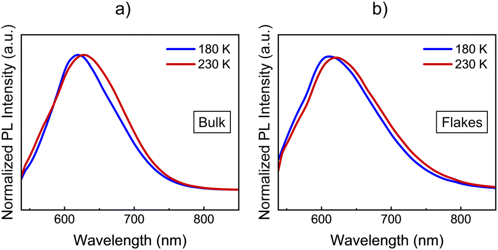 | ||
| Fig. 8 Comparison between the HS and LS PL spectra of 1 in (a) bulk and (b) flakes. Blue spectra correspond to the LS at 180 K and red spectra correspond to the HS at 230 K. Spectra have been normalized for the sake of an easier visual comparison. | ||
In this way, in order to confirm that these subtle PL emission changes are related to the SCO of the flakes and obtain robust experimental evidence of it, Raman spectra of the exfoliated flakes of 1 were measured in the same temperature range of the bulk. CN vibrations of the flakes display a shift to lower wavelengths between 180 K and 210 K (represented in Fig. 9a with grey dash lines), matching the SCO transition reported in the bulk. This can be observed in the three bands at 2180, 2200, and 2210 cm−1, although the shift is more noticeable in the vibrational band at 2200 cm−1. Compared with the Zn reference, this shift is also enhanced. While the 2200 cm−1 vibrational band shifts 12 cm−1 from 100 K to room temperature, the two vibrational bands in the reference shift ∼7 cm−1. On the other hand, in Fig. 9b we focus on the Raman vibrations in the range of 1350 to 1510 cm−1. In this case, an effect on the Raman emission can also be noticed at the same temperature range between 180 K and 210 K. Here, the vibrational band at 1375 cm−1 undergoes a shift to higher frequencies as the temperature decreases below 200 K, while the intensity of the second peak at 1385 cm−1 lowers until is not possible to track it below 180 K, coinciding with the LS state of the material (see Fig. 9b). In addition, the spectral shape of the Raman vibration observed at 1480 cm−1 is also modified in the same temperature range of the SCO (see Fig. S17 for the full temperature range, ESI†). Hence, with these measurements, we studied how the SCO electronic transition has an impact on the optical properties of 1 after the exfoliation. Thus, these measurements suggest that the spin transition is preserved in the exfoliated flakes with a small interplay between the spin transition and the resonant luminescence.
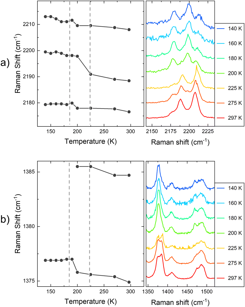 | ||
| Fig. 9 (a) Raman shift of the CN vibration with the temperature of 1 flakes. (b) Raman shift in the range between 1350 and 1510 cm−1 of 1 flakes. The plot at the left represents the central frequency of the identified Raman vibrational bands. The plot at the right shows the actual Raman spectra recorded in the flakes. | ||
Finally, in the case of 2, drastic changes in the resonant PL were not observed in the 80–260 K temperature range (Fig. S13a, ESI†). This is consistent with the lack of changes in the Raman spectra in the same temperature range (Fig. S16, ESI†). These results indicate either that the transition has no impact on the optical properties of 2 flakes, or that the SCO of the bulk crystals of 2 is lost after exfoliation and that, as a result of this, the resonant PL does not show significant changes with the temperature. The loss of SCO properties of the bulk upon miniaturisation is not uncommon and has been previously observed in nanoparticles32 and thin films.33,34
Experimental section
All chemicals are commercially available and were used as received without further purification. Caution! Perchlorate salts are explosive when subjected to heat or friction, they must be handled with care. Syntheses of furtrz, saltrz, 2, 1·Zn and 2·Zn are reported in the ESI.†Synthesis of [FeII(furtrz)2(Pt(CN)4)]·4(H2O) (1)
Fe(ClO4)2·xH2O (43.44 mg, 0.12 mmol) and furtrz (38,88 mg, 0.24 mmol) in 3 mL of 1![[thin space (1/6-em)]](https://www.rsc.org/images/entities/char_2009.gif) :1 water/EtOH were carefully layered on top of K2[Pt(CN)4]2 (44 mg, 0.12 mmol) in 3 mL of water. After a week, Yellowish plates of 1 suitable for single-crystal X-ray diffraction analysis were obtained. The crystals were filtered and washed with abundant water. Anal. Calcd for FePt(N4C7H6O)2(CN)4(H2O)3: C, 29.40; H, 2.74; N, 22.86%. Found: C, 29.20; H, 2.53; N, 22.86%.
:1 water/EtOH were carefully layered on top of K2[Pt(CN)4]2 (44 mg, 0.12 mmol) in 3 mL of water. After a week, Yellowish plates of 1 suitable for single-crystal X-ray diffraction analysis were obtained. The crystals were filtered and washed with abundant water. Anal. Calcd for FePt(N4C7H6O)2(CN)4(H2O)3: C, 29.40; H, 2.74; N, 22.86%. Found: C, 29.20; H, 2.53; N, 22.86%.
Structural characterization
Single crystals of 1, 1·Zn and 2·Zn were mounted on a glass fiber using a viscous hydrocarbon oil to coat the crystal and then transferred directly to the cold nitrogen stream for data collection. X-ray data were collected at 120 K, 204 K and 240 K for 1 and 120 K for 1·Zn and 2·Zn, on Rigaku Oxford diffraction Supernova diffractometer equipped with a graphite-monochromated Enhance (Mo) X-ray Source (λ = 0.710 73 Å) (1) and on a XtaLAB Synergy-DW diffractometer equipped with a HyPix detector and a Cu X-ray source (λ = 1.54–184 Å) (1·Zn and 2·Zn). 1 presents higher Rint values as we go higher in temperature due to the thermal vibration of the atoms and the fact that we could not grow thicker crystals (see Table S1, ESI†). The program CrysAlisPro, Rigaku Oxford Diffraction Ltd., was used for unit cell determinations and data reduction. Empirical absorption correction was performed using spherical harmonics, implemented in the SCALE3 ABSPACK scaling algorithm. The structures were solved with the ShelXT structure solution program35 and refined with the SHELXL-2013 program,36 using Olex2.28 Non-hydrogen atoms were refined anisotropically, and hydrogen atoms were placed in calculated positions refined using idealized geometries (riding model) and assigned fixed isotropic displacement parameters. In the structure of 1 at 240 K large positive and negative residual densities are reported due to the low quality of the data due to solvent disorder. Crystallographic data are summarized Table S1 (ESI†). CCDC-2299137–2299140 and 2305594 contain the supplementary crystallographic data for this paper. Additional crystallographic information is available in the ESI.† For powder X-ray diffraction patterns, a 0.5 mm glass capillary was filled with polycrystalline samples of the complexes and mounted and aligned on an Empyrean PANalytical powder diffractometer, using Cu Kα radiation (λ = 1.54–1 77 Å). A total of three scans were collected for each compound at different temperatures, between 300 K and 160 K, in the 2θ range of 5–40°.Physical characterization
The Fe/Pt and Zn/Pt ratios were measured with a Philips ESEM X230 scanning electron microscope equipped with an EDAX DX-4 microsonde. Elemental analyses (C, H, and N) were performed with a CE Instruments EA 1110 CHNS elemental analyzer. Magnetic measurements were performed with a Quantum Design MPMS-XL-5 SQUID magnetometer in the 2–300 K temperature range with an applied magnetic field of 0.1 T at a scan rate of 2 K min−1. Photomagnetic measurements were performed irradiating with a Diode Pumped Solid State Laser DPSS-532-20 from Chylas and coupled via an optical fiber to the cavity of the SQUID magnetometer. The optical power at the sample surface was adjusted to ∼3 mW cm−2. Significant change in magnetic response due to heating of the sample was not observed. The photomagnetic samples consisted of a thin layer of compound whose weight was corrected by comparison of a thermal spin-crossover curve with that of a more accurately weighted sample of the same compound.Optical microscopy and AFM.
Optical images were obtained with a Nikon Eclipse LV-100 Optical microscope and AFM images were performed with a Nanoscope IVa multimode scanning probe microscope (Bruker) in tapping mode.Raman spectroscopy
Raman spectroscopic characterization was carried out on a LabRAM HR Evolution confocal Raman microscope (Horiba). The measurements were conducted with an excitation wavelength of λexc = 532 nm. The laser was focused using a 100× objective (0.8 NA), thus leading to a laser spot with a diameter of ca. 1 μm. A CCD camera was employed to collect the backscattered light that was dispersed by an 1800 grooves per mm grating providing a spectral resolution of ∼1 cm−1. The corresponding Raman spectra were then constructed by processing the data using Lab Spec 5 software.Photoluminescence spectroscopy
PL measurements have been carried out on an ensemble spectroscopy set-up arranged on an optical table. Both, a 532 nm Nd:YAG laser and 325 nm UV diode have been used to measure the different bulk and exfoliated samples. Laser power has been maintained in all the cases inside the linear excitation regime to avoid possible damage to the sample. The excitation light is collimated, passed through a set of mirrors to the sample placed in a closed-cycle cryostat. Then, backscattering was directed through a beam splitter to the spectrometer entrance. The PL and Raman signal are then analysed with cooled silicon back-thinned CCD attached to the spectrometer. The data analysis and the band deconvolution presented in supporting information have been treated by using Origin 2021.Conclusions
Beyond the synthesis and characterization of a new 2D SCO Hofmann-type CP incorporating a luminescent ligand in 1, this work confirms the use of CP in the search of multifunctional synergetic nanomaterials as a suitable strategy. 1 and the previously reported 2 combine thermal spin transition and luminescent properties in the solid state. In the case of 2, we demonstrate in this work that there is a synergy between both properties as the spin state induces drastic changes in the emission properties. Else, the layered structure and the flexibility provided by the ligands allows the miniaturization of the two compounds through mechanical exfoliation obtaining high quality flakes of 1 and 2. 1 has demonstrated to maintain its thermal SCO properties in flakes, which is accompanied by small changes in the resonant emission as observed for the bulk material. We believe these results may be relevant for the next generation of light-sensitive SCO-based nano-devices.Conflicts of interest
There are no conflicts to declare.Acknowledgements
Financial support from the EU (ERC Advanced Grant MOL-2D 788222 and Pahfinderopen-01 4D-NMR 101099676), the Spanish MCIN (Grants PID2020-117264GB-I00 and PID2020-117152RB-I00 funded by MCIN/AEI/10.13039/501100011033 and Unidad de Excelencia María de Maeztu CEX2019-000919-M) and the Generalitat Valenciana (PROMETEO program), is acknowledged. This study forms part of the Advanced Materials programme and was supported by MCIN with funding from the European Union NextGenerationEU (PRTR-C17.I1) and by Generalitat Valenciana. Funding of the Plan GenT from Generalitat Valenciana (CIDEGENT/2018/005) to J. C.-F is acknowledged. We all thank Alejandra Soriano-Portillo for PXRD measurements, J. M. Martínez-Agudo and G. Agustí for Raman and magnetic measurements and Á. López-Muñoz for their constant technical support and helpful discussions.Notes and references
- M. K. Javed, A. Sulaiman, M. Yamashita and Z. Y. Li, Coord. Chem. Rev., 2022, 467, 214625 Search PubMed.
- L. Salmon, G. Molnár, D. Zitouni, C. Quintero, C. Bergaud, J. C. Micheau and A. Bousseksou, J. Mater. Chem., 2010, 20, 5499–5503 RSC.
- K. Senthil Kumar and M. Ruben, Coord. Chem. Rev., 2017, 346, 176–205 CrossRef CAS.
- C. Bartual-Murgui, A. Akou, C. Thibault, G. Molnár, C. Vieu, L. Salmon and A. Bousseksou, J. Mater. Chem. C, 2015, 3, 1277–1285 RSC.
- Y. Garcia, F. Robert, A. D. Naik, G. Zhou, B. Tinant, K. Robeyns, S. Michotte and L. Piraux, J. Am. Chem. Soc., 2011, 133, 15850–15853 CrossRef CAS PubMed.
- B. Benaicha, K. Van Do, A. Yangui, N. Pittala, A. Lusson, M. Sy, G. Bouchez, H. Fourati, C. J. Gómez–García, S. Triki and K. Boukheddaden, Chem. Sci., 2019, 10, 6791–6798 RSC.
- J. Yuan, M. J. Liu, S. Q. Wu, X. Zhu, N. Zhang, O. Sato and H. Z. Kou, Inorg. Chem. Front., 2019, 6, 1170–1176 RSC.
- B. X. Luo, Y. Pan, Y. S. Meng, Q. Liu, J. Yin, T. Liu and Y. Y. Zhu, Eur. J. Inorg. Chem., 2021, 3992–3999 CrossRef CAS.
- C. Lochenie, K. Schötz, F. Panzer, H. Kurz, B. Maier, F. Puchtler, S. Agarwal, A. Köhler and B. Weber, J. Am. Chem. Soc., 2018, 140, 700–709 CrossRef CAS PubMed.
- J. Y. Ge, Z. Chen, L. Zhang, X. Liang, J. Su, M. Kurmoo and J. L. Zuo, Angew. Chem., Int. Ed., 2019, 58, 8789–8793 CrossRef CAS PubMed.
- S. Ghosh, S. Kamilya, T. Pramanik, M. Rouzières, R. Herchel, S. Mehta and A. Mondal, Inorg. Chem., 2020, 59, 13009–13013 CrossRef CAS PubMed.
- J. Wang, M. Kong, X. J. Song, Y. Jing, Y. Zhao and Y. Song, Inorg. Chem., 2022, 61, 20923–20930 CrossRef CAS PubMed.
- T. Delgado, M. Meneses-Sánchez, L. Piñeiro-López, C. Bartual-Murgui, M. C. Muñoz and J. A. Real, Chem. Sci., 2018, 9, 8446–8452 RSC.
- M. Meneses-Sánchez, L. Piñeiro-López, T. Delgado, C. Bartual-Murgui, M. C. Muñoz, P. Chakraborty and J. A. Real, J. Mater. Chem. C, 2020, 8, 1623–1633 RSC.
- R. Turo-Cortés, M. Meneses-Sánchez, T. Delgado, C. Bartual-Murgui, M. C. Muñoz and J. A. Real, J. Mater. Chem. C, 2022, 10, 10686–10698 RSC.
- M. C. Muñoz and J. A. Real, Coord. Chem. Rev., 2011, 255, 2068–2093 CrossRef.
- Z. P. Ni, J. L. Liu, M. N. Hoque, W. Liu, J. Y. Li, Y. C. Chen and M. L. Tong, Coord. Chem. Rev., 2017, 335, 28–43 CrossRef CAS.
- C. F. Wang, J. Chuan and Q. Li, Inorg. Chem. Front., 2022, 9, 3251–3258 RSC.
- F. F. Yan, W. J. Jiang, N. T. Yao, P. D. Mao, L. Zhao, H. Y. Sun, Y. S. Meng and T. Liu, Chem. Sci., 2023, 14, 6936–6942 RSC.
- K. Otsubo, T. Haraguchi and H. Kitagawa, Coord. Chem. Rev., 2017, 346, 123–128 CrossRef CAS.
- M. Xu, T. Liang, M. Shi and H. Chen, Chem. Rev., 2013, 113, 3766–3768 CrossRef CAS PubMed.
- T. Rodenas, I. Luz, G. Prieto, B. Seoane, H. Miro, A. Corma, F. Kapteijn, F. X. Llabrés, I. Xamena and J. Gascon, Nat. Mater., 2015, 14, 48 CrossRef CAS PubMed.
- B. J. Córdova Wong, D. Xu, S. S. Bao, L. M. Zheng and J. Lei, ACS Appl. Mater. Interfaces, 2019, 11, 12986–12992 CrossRef PubMed.
- C. D. Polyzou, O. Malina, M. Polaskova, M. Tripathi, A. B. Dalton, J. Parthenios and V. Tangoulis, J. Mater. Chem. C, 2021, 9, 15671–15682 RSC.
- C. Boix-Constant, V. García-López, E. Navarro-Moratalla, M. Clemente-León, J. L. Zafra, J. Casado, F. Guinea, S. Mañas-Valero and E. Coronado, Adv. Mater., 2022, 34, 2110027 CrossRef CAS PubMed.
- N. F. Sciortino, K. A. Zenere, M. E. Corrigan, G. J. Halder, G. Chastanet, J. F. Létard, C. J. Kepert and S. M. Neville, Chem. Sci., 2017, 8, 701–707 RSC.
- Y. M. Klein, Na. F. Sciortino, F. Ragon, C. E. Housecroft, C. J. Kepert and S. M. Neville, Chem. Commun., 2014, 50, 3838–3840 RSC.
- O. V. Dolomanov, L. J. Bourhis, R. J. Gildea, J. A. K. Howard and H. Puschmann, J. Appl. Crystallogr., 2009, 42, 339–341 CrossRef CAS.
- G. Molnár, V. Niel, A. B. Gaspar, J. A. Real, A. Zwick, A. Bousseksou and J. J. McGarvey, J. Phys. Chem. B, 2002, 106, 9701–9707 CrossRef.
- A. Abhervé, S. Mañas-Valero, M. Clemente-León and E. Coronado, Chem. Sci., 2015, 6, 4665–4673 RSC.
- J. López-Cabrelles, S. Mañas-Valero, I. J. Vitórica-Yrezábal, P. J. Bereciartua, J. A. Rodríguez-Velamazán, J. C. Waerenborgh, B. J. C. Vieira, D. Davidovikj, P. G. Steeneken, H. S. J. van der Zant, G. Mínguez Espallargas and E. Coronado, Nat. Chem., 2018, 10, 1001–1007 CrossRef PubMed.
- V. Martínez, I. Boldog, A. B. Gaspar, V. Ksenofontov, A. Bhattacharjee, P. Gütlich and J. A. Real, Chem. Mater., 2010, 22, 4271–4281 CrossRef.
- M. Kelai, V. Repain, A. Tauzin, W. Li, Y. Girard, J. Lagoute, S. Rousset, E. Otero, P. Sainctavit, M. A. Arrio, M. L. Boillot, T. Mallah, C. Enachescu and A. Bellec, J. Phys. Chem. Lett., 2021, 12, 6152–6158 CrossRef CAS PubMed.
- V. Rubio-Gimenez, C. Bartual-Murgui, M. Galbiati, A. Núñez-López, J. Castells-Gil, B. Quinard, P. Seneor, E. Otero, P. Ohresser, A. Cantarero, E. Coronado, J. A. Real, R. Mattana, S. Tatay and C. Martí-Gastaldo, Chem. Sci., 2019, 10, 4038–4047 RSC.
- G. M. Sheldrick, Acta Crystallogr., Sect. A: Found. Crystallogr., 2015, 71, 3 CrossRef PubMed.
- G. M. Sheldrick, Acta Crystallogr., Sect. C: Struct. Chem., 2015, 71, 3 Search PubMed.
Footnotes |
| † Electronic supplementary information (ESI) available. CCDC 2299137–2299140 and 2305594. For ESI and crystallographic data in CIF or other electronic format see DOI: https://doi.org/10.1039/d3tc03693f |
| ‡ V. G.-L. and F. M.-M. contributed equally to this work. |
| This journal is © The Royal Society of Chemistry 2024 |