
 Open Access Article
 This Open Access Article is licensed under a Creative Commons Attribution-Non Commercial 3.0 Unported Licence
Promoting oxygen electrode reaction kinetics in photo-assisted Li–O2 batteries through heterostructure design and built-in electric field construction†
Yinglei
Tao
a,
Tao
Wang
 *a,
Xingyu
Yu
a,
Ke
Gong
b,
Hao
Gong
d,
Haixia
Chen
a,
Xiaoli
Fan
c,
Aidi
Zhang
b,
Xianli
Huang
a,
Kun
Chang
a and
Jianping
He
a
*a,
Xingyu
Yu
a,
Ke
Gong
b,
Hao
Gong
d,
Haixia
Chen
a,
Xiaoli
Fan
c,
Aidi
Zhang
b,
Xianli
Huang
a,
Kun
Chang
a and
Jianping
He
a
aCollege of Materials Science and Technology, Jiangsu Key Laboratory of Materials and Technology for Energy Conversion, Nanjing University of Aeronautics and Astronautics, Nanjing 210016, P. R. China. E-mail: wangtao0729@nuaa.edu.cn
bEngineering Research Center of Functional Polymer Membrane Materials of Jiangsu Province, Nanjing Bready Advanced Materials Technology Co., Ltd, No. 8 Baoding Road, Nanjing, 211103, P. R. China
cSchool of Materials Science and Engineering, Nanjing Institute of Technology, Nanjing, 211167, P.R. China
dDepartment of Chemistry and Materials Science, College of Science, Nanjing Forestry University, Nanjing 210037, P. R. China
First published on 20th September 2024
Abstract
Li–O2 batteries (LOBs) boast an exceptionally high theoretical energy density; however, the slow kinetics of the oxygen electrode reaction have been a significant hurdle in their advancement and practical application. In this study, a composite of bismuth oxyhalide heterojunction incorporated with metal–organic frameworks (MOFs) was engineered on carbon cloth (Zr-MOF/BiOIBr/CC) as an efficient bifunctional catalyst to enhance the oxygen electrode reaction in photo-assisted LOBs. Compared to Zr-MOF/CC, Zr-MOF/BiOIBr/CC significantly expands the light absorption spectrum of the catalyst. Furthermore, the built-in electric field in the heterojunction aids in the separation and directional movement of photogenerated carriers, thereby expediting the reaction kinetics of LOBs. Consequently, the photo-assisted LOBs with Zr-MOF/BiOIBr/CC as the cathodes display a discharge potential of 3.05 V, a low charge potential of 3.20 V, and an energy efficiency of up to 95.3%, and can sustain an extended cycle life of over 255 cycles. This study underscores the potential application of MOFs/semiconductor heterostructural materials in photo-assisted LOBs and offers insights into the systematic design of photo-assisted air batteries and other advanced semiconductors.
1. Introduction
In the modern era, grappling with pressing challenges including energy, environmental protection, and economic issues, aprotic Li–O2 batteries (LOBs) are identified as one of the most promising energy storage systems owing to their astonishing theoretical energy density.1–3 Unlike conventional lithium-ion batteries, LOBs achieve an energy density of up to 3500 W h kg−1 through redox electrochemical reactions (2Li+ + O2 + 2e− ↔ Li2O2).4,5 However, the sluggish reaction kinetics of the oxygen reduction reaction (ORR) and oxygen evolution reaction (OER) in LOBs hinder their further development and practical deployment.6 Consequently, devising efficient cathode catalysts to effectively promote the oxygen electrode reactions is paramount for advancing the development and application of LOBs. At present, the design and research on LOB cathode catalysts mainly focus on precious metals and their compounds,7,8 but are limited due to their scarcity and high cost. Metal oxides,9–11 metal sulfides,12,13 and carbon materials14,15 are also widely used in LOB cathode catalysts. However, due to factors such as slow catalytic kinetics, it is difficult to achieve effective charge transfer between Li2O2 and the cathode. The high overpotential generated during charging, resulting in low energy efficiency and poor cycle life, still cannot be effectively solved.To address the aforementioned issues, an intuitive and effective approach is to use efficient optoelectronic semiconductor catalysts.16–21 Upon light excitation, a substantial quantity of photogenerated electrons and holes will be generated to engage in the ORR/OER processes of LOBs, greatly enhancing the kinetics of the reaction. For instance, Wu et al.22 synthesized a CVO@CNT catalyst that not only successfully reduces the high overpotential generated during the charging process, but also effectively reduces the occurrence of side reactions. Lv et al.23 reported a Co-TABQ material serving as a bifunctional catalyst for photo-assisted LOBs, achieving an ultra-low charge/discharge overpotential of 0.20 V and an energy efficiency of up to 94%. Yang et al.24 designed a bimetallic organic framework (MOF) Fe-UiO-66, which achieved an extension of visible light response and reduced the charge/discharge overpotential to 0.14 V.
However, most photocatalysts currently employed in photo-assisted LOBs exhibit a limited light absorption range, and can only absorb ultraviolet light, making it difficult to effectively utilize light energy.25 In addition, they also face issues such as high recombination rates of photogenerated carriers and mismatch between the band structure and the ORR and OER kinetics of LOBs.26 By constructing efficient heterojunction systems (such as type II, Z-type, and S-type heterojunctions), the recombination of electrons and holes can be effectively suppressed, and the light absorption range of photocatalysts can be expanded.26–29 Therefore, it is important and challenging to design a heterojunction structure that can match the redox kinetics of photo-assisted LOBs, allowing more photogenerated electrons and holes to participate in the ORR/OER processes, effectively improving the reaction kinetics of LOBs, thereby fundamentally reducing charge–discharge overpotential and enhancing cycling stability.
MOFs have gained recognition as powerful candidates for catalyzing LOB reactions benefiting from their adjustable structure and abundant active sites.30,31 Some MOFs exhibit semiconductor properties in various photocatalytic applications by absorption of visible light to generate photo-carriers, participating in the ORR and OER, and promoting reaction kinetics.32,33 In addition, the large surface area and abundant pore structure of MOFs provide more exposed active sites and transport channels.34,35 The aforementioned characteristics of MOFs demonstrate their potential as photoelectrodes for photo-assisted LOBs, facilitating the progress of the ORR and OER.
This article reports a MOF composite bismuth halide oxide heterojunction (Zr-MOF/BiOIBr/CC) grown on carbon cloth as an efficient bifunctional cathode catalyst for photo-assisted LOBs. In comparison to Zr-MOF/CC, Zr-MOF/BiOIBr/CC not only broadens the light absorption range of the catalyst but also effectively promotes the separation and directional migration of photogenerated carriers in the heterojunction, significantly enhancing the reaction kinetics of LOBs. This enables photo-assisted LOBs with Zr-MOF/BiOIBr/CC as the cathode to achieve a discharge/charge potential of 3.05/3.20 V, with an energy efficiency of up to 95.3%, and an ultra-long cycle life of over 250 cycles. This work will serve as inspiration for the development of photo-assisted air batteries and other advanced semiconductor systems.
2. Experimental section
2.1 Chemicals
2-Aminoterephthalic acid (NH2-BDC), zirconium tetrachloride (ZrCl4), acetic acid (AA), bismuth nitrate pentahydrate (Bi(NO3)3·5H2O), sodium bromide (NaBr), potassium iodide (KI), lithium bis-trifluoromethane sulfonimide salt (LiTFSI, ≥99%), and TEGDME were purchased from Aladdin Chemical Co., Ltd. Nitric acid (HNO3), N,N-dimethylformamide (DMF), ethanol (C2H5OH, ≥99%), and methanol (MeOH, ≥99%) solvents were purchased from China National Pharmaceutical Group Chemical Reagent Co., Ltd. Carbon fiber cloth (CC) was purchased from Taiwan Carbon Energy.2.2 Materials preparation
![[thin space (1/6-em)]](https://www.rsc.org/images/entities/char_2009.gif) :water; volume ratio of 1:2) for 12 h to ensure sufficient carboxylation of the carbon cloth. Afterwards, remove the carbon cloth and rinse thoroughly with deionized water. Finally, dry the preprocessed carbon cloth under vacuum for 12 h and mark it as CC.
:water; volume ratio of 1:2) for 12 h to ensure sufficient carboxylation of the carbon cloth. Afterwards, remove the carbon cloth and rinse thoroughly with deionized water. Finally, dry the preprocessed carbon cloth under vacuum for 12 h and mark it as CC.
2.3 Characterization
The surface morphology of Zr-MOF/CC and Zr-MOF/BiOIBr/CC was observed by ionization dual beam scanning electron microscopy (SEM, Hitachi SU8010). TEM and element mappings were used to analyze the powder scraped from Zr-MOF/BiOIBr/CC using a JEOL JEM 2100F. The crystal structures of Zr-MOF/CC and Zr-MOF/BiOIBr/CC were characterized using an X-ray diffractometer (XRD) with a radiation range of 5–60°. Fourier transform infrared (FT-IR) spectra were obtained using a Thermo Scientific Nicolet iS10. The elemental composition and chemical valence states of Zr-MOF/CC and Zr-MOF/BiOIBr/CC were studied using X-ray photoelectron spectroscopy (XPS). The work functions of Zr-MOF and BiOIBr were measured using UPS. UV-vis spectra were obtained using a Shimadzu UV-3600 spectrophotometer. A three-electrode system was constructed, and the Mott–Schottky curve was obtained using an electrochemical workstation (CHI) to determine the conduction band (CB) of Zr-MOF/CC and BiOIBr/CC. The photoluminescence (PL) spectrum was obtained using the Aminco Bowman Series2 fluorescence spectrometer. The generation of discharge product Li2O2 was detected using a Raman spectrometer (HORIBA Scientific LabRAM HR Evolution).2.4 Electrochemical measurements
The synthesized Zr-MOF/CC and Zr-MOF/BiOIBr/CC were used as self-supporting electrodes, and the battery was assembled using a self-made device. Assemble the battery in a glove box containing Ar (O2 < 0.01 ppm, H2O < 0.01 ppm) using a synthesized self-supporting electrode as the cathode, 1 M LiTFSI/TEGDME as the electrolyte, glass fiber (Whatman GF/D) as the separator, and lithium metal foil as the anode. Fill the assembled LOB with oxygen for testing, with an effective illumination area of 0.2 cm2. Use a 300 W xenon lamp equipped with an AM 1.5G filter as the light source. Perform ORR and OER tests in the range of 2.5–3.2 V and 3.0–4.0 V, respectively, to obtain linear sweep voltammetry (LSV) curves with a scan rate of 5 mV s−1. Within 0–5 hours, turn on and off the light every 1 hour and draw a voltage–time (V–t) curve. Perform electrochemical impedance spectroscopy (EIS) testing using a Zahner electrochemical workstation in the frequency range of 0.1–105 Hz. Use a CHI660E electrochemical workstation to obtain the cyclic voltammetry (CV) curve. Obtain the electrochemical performance of LOBs using a LAND battery testing system.3. Results and discussion
The synthesis process of the Zr-MOF/BiOIBr/CC self-supporting cathode is shown in Fig. 1. Zr-MOF octahedral particles and BiOIBr nanosheets were successively grown on carbon cloth by a solvothermal method and chemical bath deposition method. In short, Zr-MOF particles were first grown on acidified carbon cloth by a solvothermal method. The covalent binding of Zr4+ ions in Zr-MOF with the –COOH group on the acidified carbon cloth results in strong adhesion between the Zr-MOF and the surface of the carbon cloth.36 Then, BiOIBr nanosheets were further grown on Zr-MOF/CC by a chemical bath deposition method, denoted as Zr-MOF/BiOIBr/CC, and used as efficient bifunctional cathode catalysts for photo-assisted LOBs. The heterojunction formed between the two greatly enhances the photocatalytic ability. The specific steps are provided in the Experimental section.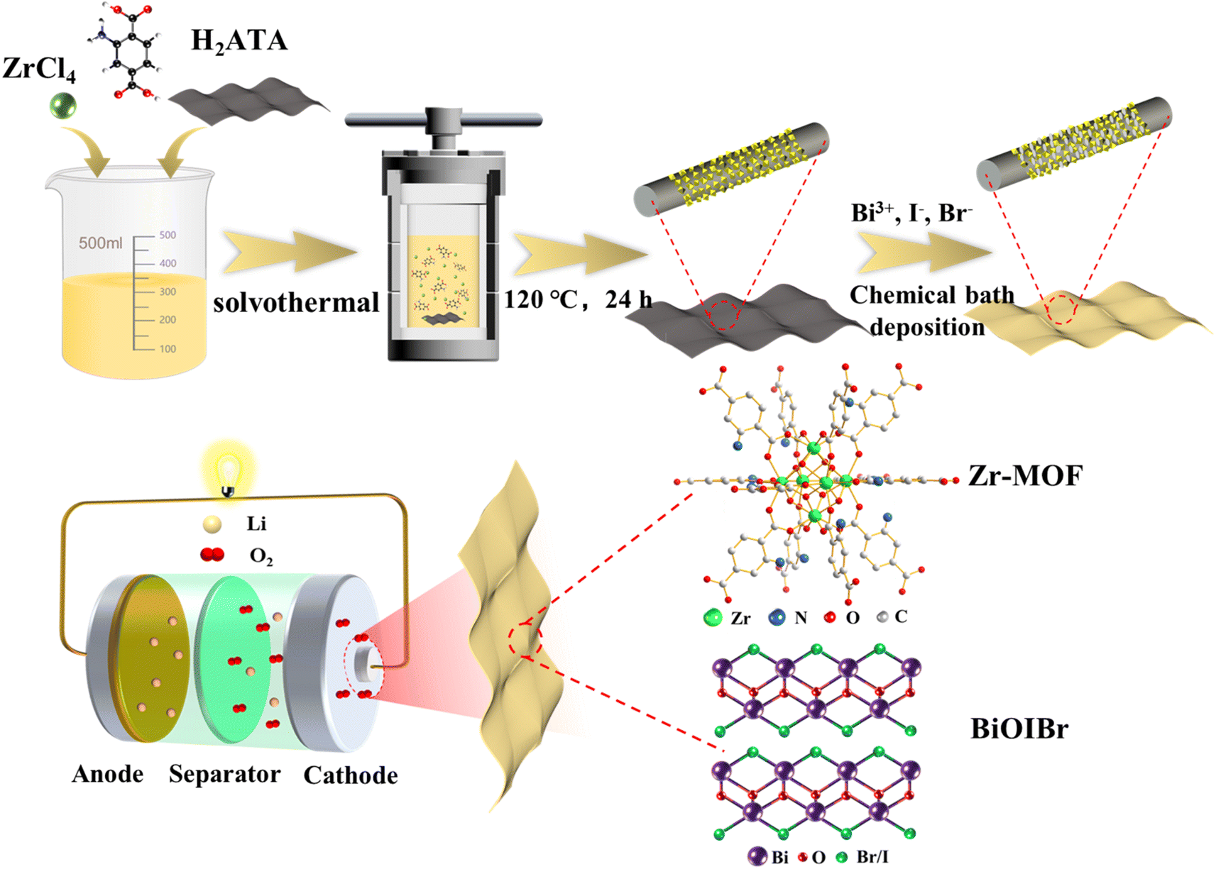 | ||
| Fig. 1 Schematic diagram of the preparation of Zr-MOF/BiOIBr/CC. | ||
The microstructural morphology of Zr-MOF/CC and Zr-MOF/BiOIBr/CC was characterized using scanning electron microscopy (SEM). Fig. 2a illustrates the Zr-MOF octahedral particles grown on the carbon cloth, demonstrating a relatively uniform distribution across the fabric with no large-scale agglomeration or stacking, and with particle sizes predominantly ranging from 100 to 300 nm. In the SEM images of Zr-MOF/BiOIBr/CC, as shown in Fig. 2b and c, sheet-like products with a size of approximately 300 nm were observed, corresponding to BiOIBr nanosheets. Additionally, the observation of the combination of nanosheets with octahedral particles confirms the successful fabrication of Zr-MOF/BiOIBr/CC. Furthermore, TEM tests were conducted to further verify the formation of heterostructures between Zr-MOF and BiOIBr, as depicted in Fig. 2d–f. Fig. 2f clearly shows the lattice stripe spacing of 0.281 nm, corresponding to the (110) crystal planes of BiOI and BiOBr, and forms a clear heterostructure with Zr-MOF, which preliminarily proves the successful construction of the Zr-MOF/BiOIBr heterojunction. Furthermore, it is worth noting that the lattice spacing of 0.281 nm is located between 0.278 nm of the BiOBr (110) plane and 0.282 nm of the BiOI (110) plane, indicating the existence of BiOIBr in the form of a solid solution.37 The elemental mappings depicted in Fig. 2g illustrate a homogeneous distribution of Zr, Bi, I, and Br elements.
 | ||
| Fig. 2 (a) SEM image of Zr-MOF/CC, (b and c) SEM images of Zr-MOF/BiOIBr/CC, (d–f) TEM images of Zr MOF/BiOIBr, and (g) elemental mappings of Zr, Bi, I, and Br. | ||
The crystal structures of the samples were analyzed by XRD, as shown in Fig. 3a. The obtained Zr-MOF/CC and Zr-MOF/BiOIBr/CC exhibit distinct diffraction peaks at 7.3° and 8.4°, which is consistent with the simulated diffraction peaks of Zr-MOF (Fig. S1†). A broad peak between 20° and 30° belongs to the diffraction peak of CC. In addition, diffraction peaks belonging to BiOI and BiOBr were observed in the Zr-MOF/BiOIBr/CC samples, which highly matched the standard PDF cards of BiOI (JCPDS: 10-0445) and BiOBr (JCPDS: 09-0393), further proving the successful synthesis of Zr-MOF/BiOIBr/CC materials. In addition, as shown in Fig. S2,† compared with the standard diffraction peak of BiOI at 2θ = 29.66°, the diffraction peak of Zr-MOF/BiOIBr/CC is offset to the right by a small angle, making the diffraction peak of Zr-MOF/BiOIBr/CC reach 30.15°. At the same time, compared with the standard diffraction peak of BiOBr at 2θ = 32.28°, the diffraction peak of Zr-MOF/BiOIBr/CC is shifted to the left by a small angle, making the diffraction peak of Zr-MOF/BiOIBr/CC reach 30.03°. The above results once again prove that BiOBr and BiOI are not independent phases, but form a BiOIBr solid solution.38 In the FTIR spectrum (Fig. 3b), the peaks at 1570 and 1256 cm−1 are attributed to the tensile vibration of –COOH and the shear vibration of C–N in Zr-MOF.39,40 The broad peak at 3429 cm−1 corresponds to the absorption peak of O–H of adsorbed water molecules. In addition, a stretching vibration absorption peak attributed to the Bi–O bond was observed at 510 cm−1 of BiOIBr/CC (Fig. S3†), but it was not found in Zr-MOF/BiOIBr/CC, which may be due to the weak absorption peak intensity of the Bi–O bond.41
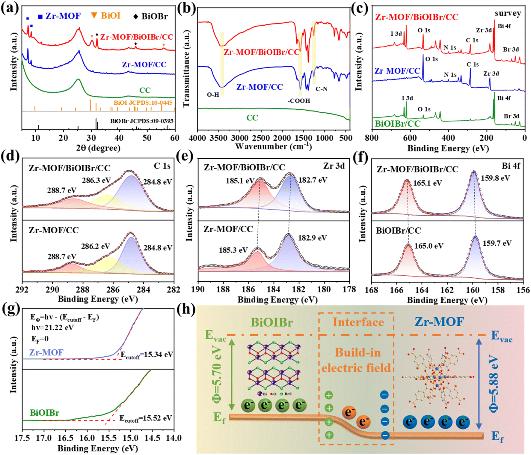 | ||
| Fig. 3 (a) XRD spectra of CC, Zr-MOF/CC, and Zr-MOF/BiOIBr/CC, (b) FT-IR spectroscopy, XPS of (c) survey, (d) C 1s, (e) Zr 3d, (f) Bi 4f, (g) UPS spectra, and (h) schematic diagram of the formation of BIEF in Zr-MOF and BiOIBr. | ||
To further analyze the elemental composition and chemical valence states of BiOIBr/CC, Zr-MOF/CC, and Zr-MOF/BiOIBr/CC, XPS testing was conducted. The survey spectrum in Fig. 3c shows that BiOIBr/CC contains Br, I, O, and Bi elements, while Zr-MOF/CC contains signals of C, O, N, and Zr elements. Zr-MOF/BiOIBr/CC showed the coexistence of many elements mentioned above, indicating that after loading Zr-MOF on the carbon cloth, BiOIBr was further successfully introduced, which is consistent with the conclusions obtained from XRD and SEM images. In the C 1s spectrum of Zr-MOF/CC and Zr-MOF/BiOIBr/CC (Fig. 3d), the peak at 284.8 eV belongs to the carbon component on the benzene ring, while the peaks at 286.3 and 288.7 eV belong to C–N and O–C![[double bond, length as m-dash]](https://www.rsc.org/images/entities/char_e001.gif) O.42 In the Zr 3d spectrum (Fig. 3e), Zr-MOF/BiOIBr/CC exhibits two distinct characteristic peaks at 182.7 and 185.1 eV, attributable to Zr 3d5/2 and Zr 3d3/2. In addition, compared with the peak values of Zr-MOF/CC at 182.9 and 185.3 eV, the binding energy of Zr-MOF/BiOIBr/CC shows a slight negative shift (∼0.2 eV). In the Bi 4f spectrum (Fig. 3f), the characteristic peaks of Zr-MOF/BiOIBr/CC at 159.8 and 165.1 eV show a slight positive shift in binding energy (∼0.1 eV) compared to the peaks of BiOIBr/CC at 159.7 and 165.0 eV. Shifting towards higher binding energy signifies a reduction in electron cloud density, whereas shifting towards lower binding energy demonstrates an increase in electron cloud density.43 Therefore, this confirms the strong interaction between Zr-MOF and BiOIBr, where electrons migrate from BiOIBr to Zr-MOF. The strong electron interaction between them is conducive to the construction of heterogeneous structures and the formation of built-in electric fields (BIEF).26,44
O.42 In the Zr 3d spectrum (Fig. 3e), Zr-MOF/BiOIBr/CC exhibits two distinct characteristic peaks at 182.7 and 185.1 eV, attributable to Zr 3d5/2 and Zr 3d3/2. In addition, compared with the peak values of Zr-MOF/CC at 182.9 and 185.3 eV, the binding energy of Zr-MOF/BiOIBr/CC shows a slight negative shift (∼0.2 eV). In the Bi 4f spectrum (Fig. 3f), the characteristic peaks of Zr-MOF/BiOIBr/CC at 159.8 and 165.1 eV show a slight positive shift in binding energy (∼0.1 eV) compared to the peaks of BiOIBr/CC at 159.7 and 165.0 eV. Shifting towards higher binding energy signifies a reduction in electron cloud density, whereas shifting towards lower binding energy demonstrates an increase in electron cloud density.43 Therefore, this confirms the strong interaction between Zr-MOF and BiOIBr, where electrons migrate from BiOIBr to Zr-MOF. The strong electron interaction between them is conducive to the construction of heterogeneous structures and the formation of built-in electric fields (BIEF).26,44
The magnitude of the material work function (EΦ) determines the direction of electron migration, which is actually determined by the energy level difference between Fermi levels. Therefore, a smaller EΦ makes it easier for electrons to escape when two materials are combined.45 In order to elucidate the formation of BIEF and the driving mechanism of electron migration, UPS characterization was performed (Fig. 3g). It can be calculated that when the Fermi level (Ef) is 0 eV, the EΦ is defined as the difference between the energy of photons (hν) and the cutoff energy for secondary electron emission (Ecutoff), that is, EΦ = hv − (Ecotoff − Ef). Therefore, the calculated EΦ values of Zr-MOF and BiOIBr are 5.88 and 5.70 eV, respectively.46 And the formation mechanism of the BIEF is shown in Fig. 3h. Due to the relatively high Ef of BiOIBr compared to Zr-MOF, when the two come into contact, electrons will spontaneously transfer from the Ef of BiOIBr to Zr-MOF until the Ef on both sides reaches equilibrium. Therefore, the side close to Zr-MOF is negatively charged due to electron enrichment, while the side of BiOIBr is positively charged due to hole enrichment, resulting in a potential difference, and forming BIEF.47 The formation of the BIEF can effectively promote the separation and directional migration of charge carriers, thereby accelerating the reaction kinetics of Li–O2 batteries.
To understand the optical properties and band gaps of Zr-MOF/CC and Zr-MOF/BiOIBr/CC, UV-vis spectrum tests were conducted (Fig. 4a). The absorption edge of Zr-MOF/CC is 455 nm, exhibiting similar light absorption to the Zr-MOF powder sample (Fig. S4†). After depositing BiOIBr on Zr-MOF/CC, the absorbance edge showed a redshift, reaching 568 nm, and the light absorption intensity was enhanced. The red shift phenomenon clearly demonstrates that the introduction of BiOIBr effectively expands the light absorption range of the material. The energy band gap (Eg) of the sample can be obtained from the Tauc plot derived from the UV-vis spectrum, as shown in Fig. 4b. The band gaps of Zr-MOF/CC and BiOIBr/CC are 2.88 and 2.12 eV, respectively. In addition, to estimate the conduction band potential (CB) of the catalyst, a three electrode system was assembled and its flat band potential (FB) was measured using the Mott–Schottky (MS) method (Fig. S5†). For n-type semiconductors, FB can be approximated as CB. Therefore, by combining the Tauc plot and Mott–Schottky plot, the VB and CB potentials of Zr-MOF and BiOIBr relative to Li+/Li can be calculated using the formula EVB = ECB + Eg, and the band structures of Zr-MOF and BiOIBr can be obtained.23Fig. 4c shows the oxidation–reduction potential of O2/Li2O2 (2.96 V), which is between the CB and VB of Zr-MOF and BiOIBr, meeting the thermodynamic conditions for the ORR/OER processes of photocatalytic LOBs.
 | ||
| Fig. 4 (a) UV-vis spectrum. (b) Tauc plot. (c) Band structure diagram. (d) PL spectrum. (e) EIS spectra of Zr-MOF/CC and Zr-MOF/BiOIBr/CC with/without illumination. (f) In situ XPS spectra under dark and irradiation conditions: Zr 3d. (g) Schematic diagram of directed transfer of photogenerated carriers under the influence of BIEF. | ||
The separation efficiency of photogenerated carriers on Zr-MOF/CC and Zr-MOF/BiOIBr/CC was evaluated using steady-state photoluminescence (PL) spectroscopy. Fig. 4d shows that the PL emission peak intensity of Zr-MOF/BiOIBr/CC is much lower than that of Zr-MOF/CC, indicating that the recombination of photogenerated carriers is suppressed and the recombination rate is significantly reduced. In addition, EIS tests were conducted to characterize the kinetics of oxygen electrode reactions of LOBs. Fig. 4e shows that compared to the corresponding dark state conditions, Zr-MOF/CC and Zr-MOF/BiOIBr/CC exhibit accelerated charge transfer kinetics under illumination. Meanwhile, compared to the Zr-MOF/CC cathode (70 Ω), the Zr-MOF/BiOIBr/CC cathode (52 Ω) exhibits lower charge transfer resistance under illumination, further proving that the formed heterostructure effectively reduces the recombination of electron and hole pairs, greatly promoting the separation and migration efficiency of carriers.
The type of heterojunction determines the migration pathway of photo-generated charge carriers, which in turn affects the reaction mechanism of photo-assisted LOBs. Given that Zr-MOF/BiOIBr/CC is composed of binary semiconductors Zr-MOF and BiOIBr, the possibility of a Z-type heterojunction can be ruled out, leaving behind the possibility of a type II or S-type heterojunction.48 In order to determine whether the interface charge between Zr MOF/BiOIBr heterojunctions follows the S-scheme transfer mechanism, in situ irradiation XPS testing was conducted. Under light excitation, in the Zr 3d spectrum (Fig. 4f), the binding energy of Zr-MOF/BiOIBr exhibits a significant negative shift (∼0.07 eV) compared to the corresponding dark state conditions. However, in the Bi 4f spectrum (Fig. S6†), there is also a significant negative shift (∼0.2 eV), which does not conform to the interface charge transfer pathway between S-type heterojunctions.26 Therefore, it can be inferred that the prepared Zr-MOF/BiOIBr/CC is a type II heterojunction. In the photocatalytic process, the photogenerated carrier directional migration pathway under the influence of BIEF is shown in Fig. 4g. As explained in detail above, the difference in Ef between Zr-MOF and BiOIBr leads to electron transfer and ultimately BIEF. Under light, the electrons on the VB of Zr-MOF and BiOIBr are excited, migrate to the CB to become photogenerated electrons, and leave photogenerated holes on the VB. Under the influence of BIEF, photogenerated electrons migrate from the CB of Zr-MOF to the CB of BiOIBr, while photogenerated holes move in the opposite direction.27,28 Therefore, BIEF formed at the contact interface of Zr-MOF and BiOIBr can effectively inhibit the recombination of carriers, promote the efficient separation of photogenerated electrons and holes, and enable them to effectively participate in the ORR/OER of LOBs.
The constant current discharge/charge curves of the Zr-MOF/CC and Zr-MOF/BiOIBr/CC electrodes with and without illumination are depicted in Fig. 5a. In the dark state, the charge/discharge overpotential of the two cathodes is notably high, reaching 1.15 V (Zr-MOF/BiOIBr/CC) and 1.20 V (Zr-MOF/CC), respectively (Fig. S7†). Conversely, under illumination, the charge/discharge overpotential of LOBs decreased significantly to 0.15 V (Zr-MOF/BiOIBr/CC) and 0.41 V (Zr-MOF/CC). It is noteworthy that the Zr-MOF/BiOIBr/CC cathode, with a discharge voltage under illumination as high as 3.05 V, exceeds the thermodynamic limit of LOB (2.96 V), while the charge voltage is significantly reduced to 3.20 V, resulting in an energy efficiency up to 95.3%. Furthermore, the LSV curves (Fig. 5b and S8†) demonstrate that the Zr-MOF/BiOIBr/CC cathode exhibits the highest ORR/OER photocurrent density under illumination, reaching −6.7/1.2 mA cm−2, which is significantly higher than the −2.9/0.4 mA cm−2 of Zr-MOF/CC. The constant current discharge/charge curves of the intermittent 1 h on-off lamp LOBs (Fig. S9†) demonstrate that the discharge voltage of Zr-MOF/CC and Zr-MOF/BiOIBr/CC cathodes rapidly increases from 2.61/2.86 V without illumination to 2.98/3.05 V with illumination, while the charge voltage simultaneously decreases rapidly from 4.43/4.27 V to 3.38/3.18 V at 0.05 mA cm−2. The above observed enhancement in the performance of Zr-MOF/BiOIBr/CC is primarily attributed to the formation of heterostructures, which effectively reduce the recombination of photogenerated electrons and hole pairs, promote the separation and migration efficiency of carriers, and facilitate their effective participation in the ORR/OER of LOBs, thereby showcasing a stronger photocatalytic capability. Additionally, CV scanning tests on Zr-MOF/BiOIBr/CC (Fig. 5c) reveal a stronger redox peak in the CV curve of the cathode under photo-assisted conditions compared to its dark state counterpart, as well as a higher ORR onset potential and a lower OER onset potential, suggesting accelerated redox reaction kinetics and excellent bifunctional catalytic activity. In addition, the CV curve under an Ar gas atmosphere shows almost no fluctuation throughout the entire working voltage range, indicating that the active substance participating in electrode reactions in the LOB system is oxygen, rather than other substances in the battery system.
 | ||
| Fig. 5 (a) Constant current discharge/charge curves of Zr-MOF/CC and Zr-MOF/BiOIBr/CC cathodes with/without illumination. (b) LSV curves during the ORR process. (c) CV curve of Zr-MOF/BiOIBr/CC cathode. The rate performance of (d) Zr-MOF/CC and (e) Zr-MOF/BiOIBr/CC cathodes under illumination. (f) Overpotential. (g) The cycling performance of Zr-MOF/BiOIBr/CC cathode with/without illumination. (h) This work compares the charging/discharging overpotential and cycling times of excellent photo-assisted LOB photocathodes reported. | ||
Fig. 5d and e show the rate performance tests of Zr-MOF/CC and Zr-MOF/BiOIBr/CC cathodes under photo-assisted conditions by changing the current density. As shown in Fig. 5e, at 0.1 mA cm−2, the discharge/charge potentials of Zr-MOF/BiOIBr/CC cathode are 3.04 V and 3.29 V, respectively, exceeding the thermodynamic limit of LOB (2.96 V), and the energy efficiency reaches 92.4%. Even at a high current density of 0.50 mA cm−2, the energy efficiency can remain at 73%. In addition, when returned to 0.1 mA cm−2, the discharge/charge potential of the Zr-MOF/BiOIBr/CC cathode can almost fully recover to its previous state. Fig. 5f summarizes the overpotentials of the two cathode materials in Fig. 5d and e at different current densities. These findings demonstrate that compared to Zr-MOF/CC, the Zr-MOF/BiOIBr/CC cathode exhibits smaller charge–discharge overpotentials at all current densities. The above results demonstrate that LOBs equipped with Zr-MOF/BiOIBr/CC as photocathodes exhibit excellent rate performance.
The cycling performance of Zr-MOF/CC and Zr-MOF/BiOIBr/CC cathodes was tested at 0.05 mA cm−2, as depicted in Fig. 5g. Under illumination, the initial charge/discharge overpotential of the Zr-MOF/CC cathode reached a high of 0.41 V and could sustain only 170 cycles. In stark contrast, the charge/discharge overpotential of the Zr-MOF/BiOIBr/CC cathode under illumination significantly decreased to 0.15 V and could sustain over 255 cycles, markedly surpassing the Zr-MOF/CC under the same conditions. These results unequivocally demonstrate that the heterostructure formed on Zr-MOF/BiOIBr/CC effectively reduces electron/hole pair recombination under illumination, enhancing carriers' participation in cathodic reactions, reducing charge/discharge overpotential, and facilitating long-term stable operation of photo-assisted LOBs. In addition, compared with the representative and excellent photo-assisted LOBs in Fig. 5h and Table S1,† it can be observed that the Zr-MOF/BiOIBr/CC electrode exhibits lower charge/discharge overpotential and excellent cycling stability. This work highlights the potential application of MOF/semiconductor heterostructure materials in photo-assisted LOBs, providing inspiration for the rational design of photo-assisted air batteries and other advanced semiconductors.
The discharge product Li2O2 of LOBs, as a typical insulating and insoluble substance, is the main reason for the excessive charging and discharging overpotential and unstable cycling performance of LOBs. Therefore, exploring the deposition and decomposition process of Li2O2 is crucial for further studying the electrochemical mechanism of LOBs. To further confirm the promoting effect of Zr-MOF/BiOIBr/CC on the deposition and decomposition of Li2O2 in catalytic reactions, the microstructure of the cathodes in different states was characterized. The SEM images of Zr-MOF/BiOIBr/CC in the pristine, discharge, and recharge states are shown in Fig. 6d–f. As a self-supporting electrode without added adhesive, many Zr-MOF octahedral particles were observed to grow on CC in the pristine state and combine with BiOIBr nanosheets. After discharge, significant film-like products were observed and uniformly coated on the surface of Zr-MOF/BiOIBr/CC, as shown in Fig. 6e. After recharge, the film-like discharge products completely disappeared, and the surface morphology of the cathode was exposed again, and it can almost return to its original state. This indicates that under the catalytic action of Zr-MOF/BiOIBr/CC, a highly reversible O2/Li2O2 conversion reaction occurred on the cathode surface. In sharp contrast, the surface of the Zr-MOF/CC cathode is also coated with film products after discharge, but there are still undecomposed products after recharge (Fig. 6a–c). In addition, to illustrate the morphological differences of Li2O2 with and without illumination, we supplemented the morphology of discharge products of Zr-MOF/CC without illumination. As shown in Fig. S10,† the morphology of Li2O2 without illumination presents a sheet-like structure (Fig. S10a†), which is significantly different from the film-like morphology of Li2O2 under illumination. According to the report by Yu et al.,49 in the absence of illumination, slow ORR kinetics lead to the enrichment of Li+, thus Li2O2 tends to grow into sheet-like under the limitation of electrostatic repulsion. Under illumination, photogenerated electrons accelerate the conversion of O2 to O2−, forming a large amount of O2− on the surface, thereby accelerating the ORR reaction kinetics. At this point, the migration rate of Li+ cannot match the ORR, resulting in the formation of film-like Li2O2 through surface growth pathways.
 | ||
| Fig. 6 SEM images of Zr-MOF/CC (a–c) and Zr-MOF/BiOIBr/CC (d–f) cathodes in various states with illumination. (g) XRD patterns of the Zr-MOF/BiOIBr/CC cathode in different states. (h) Raman spectra of the Zr-MOF/BiOIBr/CC cathode in different states. (i) XPS spectra of the Zr-MOF/BiOIBr/CC cathode in different states. | ||
To further confirm the main component of the film discharge product as Li2O2, its composition was characterized using XRD, Raman and XPS. However, the absence of a significant diffraction peak corresponding to Li2O2 in the XRD pattern of Fig. 6d may be attributed to the low content of generated Li2O2 or its formation as an amorphous film product.24,50,51 In the subsequent Raman spectrum (Fig. 6h), a characteristic peak at 790 cm−1 belonging to Li2O2 was observed and disappeared after recharge. The XPS pattern in Fig. 6i shows that a peak signal corresponding to Li2O2 is observed at 55.1 eV after discharge and completely disappears after recharge, once again confirming that the generated film discharge product is indeed Li2O2. The charge transfer impedance of LOBs in different states was assessed using EIS. As depicted in Fig. S11,† the Rct (695 Ω) of LOBs after discharge significantly increased compared to the initial state (167 Ω) due to the formation of a large amount of insulating and insoluble discharge product Li2O2 on the cathode. However, the Rct (216 Ω) decreased significantly after recharge and almost returned to its initial value, once again demonstrating the highly reversible nature of the Zr-MOF/BiOIBr/CC-catalyzed LOB reaction. Moreover, to evaluate the structural stability of Zr-MOF/BiOBr/CC after cycling, we conducted XRD testing on it. As shown in Fig. S12,† after 50 cycles, the intensity change of diffraction peaks in the XRD pattern can be ignored, which confirms the excellent structural stability of Zr-MOF/BiOBr/CC.
4. Conclusion
In summary, a Zr-MOF/BiOIBr heterojunction fabricated on carbon cloth was successfully synthesized using simple solvothermal and chemical bath deposition methods, serving as an efficient bifunctional cathode catalyst for photo-assisted LOBs. The introduction of BiOIBr expands the light absorption range of the catalyst to the visible light region, achieving effective utilization of light energy. Moreover, the BIEF formed at the interface of the heterojunctions effectively inhibits carrier recombination and promotes the efficient separation of photogenerated electrons and holes. Consequently, the highly active photogenerated electrons and holes in Zr-MOF/BiOIBr/CC actively engage in the ORR/OER in LOBs, boosting the reaction kinetics and enhancing battery performance. This enhancement results in an increased discharge voltage of 3.05 V, decreased charge voltage of 3.20 V, energy efficiency of 95.3%, and a prolonged cycle life exceeding 255 cycles. This work highlights the potential application of MOFs/semiconductor heterostructure materials in photo-assisted LOBs, offering insights into the systematic design of photo-assisted air batteries and other advanced semiconductor systems.Data availability
The data supporting this study are available within the main text and the ESI.†Author contributions
Y. T., T. W., H. C. and X. Y. designed the experiment and wrote the manuscript. Y. T., K. G., H. G. and X. F. conducted the experiments. A. Z., X. H., K. C. and J. H. analysed the data. All authors discussed the results at all stages and participated in the development of the manuscript.Conflicts of interest
There are no conflicts of interest to declare.Acknowledgements
The authors acknowledge the financial support for this work from the Fund Project for Transformation of Scientific and Technological Achievements of Jiangsu Province of China (BA2023020), the National Defense Technology Innovation Special Zone Spark Project (2016300TS00911901), the Natural Science Foundation of Jiangsu Province (BK20210616), the National Science Foundation of China (22309084) and the China Postdoctoral Science Foundation (2023M731589), the Jiangsu Key Laboratory of Electrochemical Energy-Storage Technologies (EEST2021-2), Postgraduate Research & Practice Innovation Program of NUAA (xcxjh20230614, and xcxjh20230608) and a Project Funded by the Priority Academic Program Development of Jiangsu Higher Education Institutions (PAPD). In addition, we appreciate the SEM analysis provided by the Analytical Test Center of NUAA.References
- L. Rosa, D. L. Sanchez and M. Mazzotti, Energy Environ. Sci., 2021, 14, 3086–3097 RSC.
- X. Wang, D. Du, H. Xu, Y. Yan, X. Wen, L. Ren and C. Shu, Chem. Eng. J., 2023, 452, 139524 CrossRef CAS.
- X. Wang, D. Guan, F. Li, M. Li, L. Zheng and J. Xu, Adv. Mater., 2022, 34, 2104792 CrossRef CAS PubMed.
- X. Li, Y. Su, Y. Ma, L. Wei, Y. He, Y. Gu, S. Mei, Q. Mu, C. Peng, Y. Peng and Z. Deng, Appl. Catal., B, 2023, 337, 122964 CrossRef CAS.
- X. Cao, X. Zheng, Z. Sun, C. Jin, J. Tian, S. Sun and R. Yang, Appl. Catal., B, 2019, 253, 317–322 CrossRef CAS.
- C. Shu, J. Wang, J. Long, H. Liu and S. Dou, Adv. Mater., 2019, 31, 1804587 CrossRef PubMed.
- Y. Zhou, K. Yin, Q. Gu, L. Tao, Y. Li, H. Tan, J. Zhou, W. Zhang, H. Li and S. Guo, Angew. Chem., Int. Ed., 2021, 60, 26592–26598 CrossRef CAS PubMed.
- K. Song, J. Jung, M. Park, H. Park, H.-J. Kim, S.-I. Choi, J. Yang, K. Kang, Y.-K. Han and Y.-M. Kang, ACS Catal., 2018, 8, 9006–9015 CrossRef CAS.
- Y. Zhang, S. Zhang, M. Yuan, Y. Li, R. Liu, C. Nan and C. Chen, Nano Res., 2024, 17, 221–227 CrossRef CAS.
- Z. Lian, Y. Lu, S. Ma, Z. Li and Q. Liu, Chem. Eng. J., 2022, 445, 136852 CrossRef CAS.
- G. Sun, D. Yang, Z. Zhang, Y. Wang, W. Lu and M. Feng, J. Adv. Ceram., 2023, 12, 747–759 CrossRef CAS.
- S. Ding, L. Wu, F. Zhang and X. Yuan, Small, 2023, 19, 2300602 CrossRef CAS PubMed.
- D. Li, L. Zhao, J. Wang and C. Yang, Adv. Energy Mater., 2023, 13, 2204057 CrossRef CAS.
- D. Li, L. Zhao, Q. Xia, J. Wang, X. Liu, H. Xu and S. Chou, Adv. Funct. Mater., 2022, 32, 2108153 CrossRef CAS.
- H. Liang, Z. Gai, F. Chen, S. Jing, W. Kan, B. Zhao, S. Yin and P. Tsiakaras, Appl. Catal., B, 2023, 324, 122203 CrossRef CAS.
- P. Tan, X. Xiao, Y. Dai, C. Cheng and M. Ni, Renew. Sustain. Energy Rev., 2020, 127, 109877 CrossRef CAS.
- M. Li, X. Wang, F. Li, L. Zheng, J. Xu and J. Yu, Adv. Mater., 2020, 32, 1907098 CrossRef CAS PubMed.
- M. Wang, J. Chen, Z. Tian, W. Dai, B. Cui, X. Cui, D. Wang, Y. Xiao, X. Lian, C. Jiang, H. Yang, Y. Wang, Z. Sun, Y. Ding, Y.-Y. Sun, J. Zhang and W. Chen, Energy Environ. Sci., 2023, 16, 523–534 RSC.
- L. Ren, F. Kong, X. Wang, Y. Song, X. Li, F. Zhang, N. Sun, H. An, Z. Jiang and J. Wang, Nano Energy, 2022, 98, 107248 CrossRef CAS.
- Z. Hu, Y. Yang, B. Ye, X. Hu, L. Chen, H. Yu, Y. Zhou, Z. Xie and Z. Zhou, Adv. Mater. Interfaces, 2023, 10, 2300074 CrossRef.
- R. Fan, Y. Wu, H. Xie, Y. Gao, L. Wang, B. Zhao, D. Li, S. Liu, Y. Zhang, H. Kong, Y. Li, Q. Chen, A. Cao and H. Zhou, ChemSusChem, 2022, 15, e202201473 CrossRef CAS PubMed.
- D. Li, X. Lang, Y. Guo, Y. Wang, Y. Wang, H. Shi, S. Wu, W. Wang and Q.-H. Yang, Nano Energy, 2021, 85, 105966 CrossRef CAS.
- Q. Lv, Z. Zhu, S. Zhao, L. Wang, Q. Zhao, F. Li, L. A. Archer and J. Chen, J. Am. Chem. Soc., 2021, 143, 1941–1947 CrossRef CAS PubMed.
- Y. Yang, X. Hu, G. Wang, J. Han, Q. Zhang, W. Liu, Z. Xie and Z. Zhou, Adv. Funct. Mater., 2024, 34, 2315354 CrossRef CAS.
- L.-J. Zheng, F. Li, L.-N. Song, M.-L. Li, X.-X. Wang and J.-J. Xu, Energy Storage Mater., 2021, 42, 618–627 CrossRef.
- Z. Zhu, Q. Lv, Y. Ni, S. Gao, J. Geng, J. Liang and F. Li, Angew. Chem., Int. Ed., 2022, 61, e202116699 CrossRef CAS PubMed.
- H. Xue, T. Wang, Y. Feng, H. Gong, X. Fan, B. Gao, Y. Kong, C. Jiang, S. Zhang, X. Huang and J. He, Nanoscale, 2020, 12, 18742–18749 RSC.
- G.-Y. Qiao, D. Guan, S. Yuan, H. Rao, X. Chen, J.-A. Wang, J.-S. Qin, J.-J. Xu and J. Yu, J. Am. Chem. Soc., 2021, 143, 14253–14260 CrossRef CAS PubMed.
- W. Yang, J. Zhao, Z. Li, J. Xin, F. Li and Y. Wang, J. Alloys Compd., 2023, 967, 171576 CrossRef CAS.
- W. Cheng, X. Zhao, H. Su, F. Tang, W. Che, H. Zhang and Q. Liu, Nat. Energy, 2019, 4, 115–122 CrossRef CAS.
- D. Wu, Z. Guo, X. Yin, Q. Pang, B. Tu, L. Zhang, Y. Wang and Q. Li, Adv. Mater., 2014, 26, 3258–3262 CrossRef CAS PubMed.
- R. Li, W. Zhang and K. Zhou, Adv. Mater., 2018, 30, 1705512 CrossRef PubMed.
- Y. Xiao, Y. Qi, X. Wang, X. Wang, F. Zhang and C. Li, Adv. Mater., 2018, 30, 1803401 CrossRef PubMed.
- J.-S. Lee, C. Lee, J.-Y. Lee, J. Ryu and W.-H. Ryu, ACS Catal., 2018, 8, 7213–7221 CrossRef CAS.
- H.-Q. Xu, J. Hu, D. Wang, Z. Li, Q. Zhang, Y. Luo, S.-H. Yu and H.-L. Jiang, J. Am. Chem. Soc., 2015, 137, 13440–13443 CrossRef CAS PubMed.
- W. Yu, J. Zhang, Y. Xiong, Z. Wan, J. Zhu and Y. Zhang, J. Cleaner Prod., 2023, 415, 137603 CrossRef CAS.
- M. H. Urgesa, G. S. Wolde and D.-H. Kuo, J. Alloys Compd., 2023, 947, 169589 CrossRef CAS.
- S. G. Fard, M. Haghighi and M. Shabani, Appl. Catal., B, 2019, 248, 320–331 CrossRef CAS.
- C. Zhao, Z. Yan, B. Zhou, Y. Pan, A. Hu, M. He, J. Liu and J. Long, Angew. Chem., Int. Ed., 2023, 62, e202302746 CrossRef CAS PubMed.
- S. Li, K. Ji, M. Zhang, C. He, J. Wang and Z. Li, Nanoscale, 2020, 12, 9533–9540 RSC.
- H. Li, D. Wang, C. Miao, F. Xia, Y. Wang, Y. Wang, C. Liu and G. Che, J. Environ., 2022, 10, 108201 CAS.
- Y. Su, Z. Zhang, H. Liu and Y. Wang, Appl. Catal., B, 2017, 200, 448–457 CrossRef CAS.
- T. Qian, Y. Zhang, J. Cai, W. Cao, T. Liu, Z. Chen, J. Liu, F. Li and L. Zhang, J. Colloid Interface Sci., 2021, 603, 582–593 CrossRef CAS PubMed.
- H. Jiang, M. Xu, X. Zhao, H. Wang and P. Huo, J. Environ., 2023, 11, 109504 CAS.
- R. Huang, Z. Zhai, X. Chen, X. Liang, T. Yu, Y. Yang, B. Li and S. Yin, Small, 2024, 2310808 CrossRef CAS PubMed.
- S. Mao, G. Yao, P. Liu, C. Liu, Y. Wu, Z. Ding, C. Ding, M. Xia and F. Wang, Chem. Eng. J., 2023, 470, 144250 CrossRef CAS.
- Z. Zhou, L. Zhao, J. Wang, Y. Zhang, Y. Li, S. Shoukat, X. Han, Y. Long and Y. Liu, Small, 2023, 19, 2302598 CrossRef CAS PubMed.
- P. Tan, Z. Mao, Y. Li, J. Yu and L. Long, J. Colloid Interface Sci., 2024, 663, 992–1004 CrossRef CAS PubMed.
- H. Yu, D. Liu, Z. Fu, S. Wang, X. Zuo, X. Feng and Y. Zhang, Angew. Chem., Int. Ed., 2024, 63, e202401272 CrossRef CAS PubMed.
- L. Wei, Y. Su, Y. Ma, Y. Gu, Y. Qin, X. Wu, Y. He, X. Li, Y. Peng and Z. Deng, Chem. Eng. J., 2022, 448, 137591 CrossRef CAS.
- L. Zhao, J. Feng, A. Abbas, C. Wang and H. Wang, Small, 2023, 19, 2302953 CrossRef CAS PubMed.
Footnote |
| † Electronic supplementary information (ESI) available. See DOI: https://doi.org/10.1039/d4sc04923c |
| This journal is © The Royal Society of Chemistry 2024 |