 Open Access Article
Dual-strategy engineered nickel phosphide for achieving efficient hydrazine-assisted hydrogen production in seawater†
Rui-Qing
Li
 *a,
Songyun
Guo
a,
Xiaojun
Wang
a,
Xiaoyu
Wan
a,
Shuixiang
Xie
a,
Yu
Liu
a,
Changming
Wang
a,
Guangyu
Zhang
 a,
Jun
Cao
*b,
Jiamu
Dai
a,
Mingzheng
Ge
a,
Jun
Cao
*b,
Jiamu
Dai
a,
Mingzheng
Ge
 a and
Wei
Zhang
*a
aSchool of Textile and Clothing, Nantong University, Nantong 226019, PR China. E-mail: liruiqing@ntu.edu.cn; zhangwei@ntu.edu.cn
bDepartment of Physics, Zhejiang Sci-Tech University, Hangzhou 310018, PR China. E-mail: caojun2021@zstu.edu.cn
First published on 16th May 2024
Abstract
Electrocatalytic hydrogen production in seawater to alleviate freshwater shortage pressures is promising, but is hindered by the sluggish oxygen evolution reaction and detrimental chloride electrochemistry. Herein, a dual strategy approach of Fe-doping and CeO2-decoration in nickel phosphide (Fe-Ni2P/CeO2) is rationally designed to achieve superior bifunctional catalytic performance for the hydrogen evolution reaction (HER) and hydrazine oxidation reaction (HzOR) in seawater. Notably, the two-electrode Fe-Ni2P/CeO2-based hybrid seawater electrolyzer realizes energy-efficient and chlorine-free hydrogen production with ultralow cell voltages of 0.051 and 0.597 V at 10 and 400 mA cm−2, which are significantly lower than those needed in the hydrazine-free seawater electrolyzer. Density functional theory calculations manifest that the combination of Fe doping and heterointerface construction between Fe-Ni2P and CeO2 can adjust the electronic structure of the Ni2P and optimize the water dissociation barrier and hydrogen adsorption free energy, leading to improvement of the intrinsic catalytic performance. This route affords a feasible solution for future large-scale hydrogen generation using abundant ocean water.
Introduction
Hydrogen, with its high energy-density and pollution-free emissions, is a superior energy source for the realization of carbon neutrality. Water electrolysis driven by renewable electricity is a prospective scheme to prepare hydrogen.1,2 In general, water electrolyzers employ large quantities of freshwater as the electrolyte, restricting their grid-scale deployment.3 In this context, substituting freshwater with the abundant seawater of our planet would provide an unlimited hydrogen source and alleviate freshwater shortage pressures. Seawater electrolysis involves two half reactions, namely, the hydrogen evolution reaction (HER) and the oxygen evolution reaction (OER), and the OER process limits the overall electrolytic efficiency because of its intrinsically sluggish kinetics, which lead to high cell voltages.4,5 Unfortunately, the chloride ions present inevitably undergo the chlorine evolution reaction (CER), which competes with the OER at the anode, bringing about the generation of corrosive chlorine species when the overpotential exceeds 480 mV, catalyst degradation and environmental hazards in alkaline seawater.6,7 Consequently, developing chlorine-free and energy-saving seawater electrolysis technology for sustainable hydrogen production remains a formidable challenge.8 At present, two tactics have been explored to solve the above bottlenecks. Firstly, replacing the OER with thermodynamically favorable oxidation reactions of small molecules including urea, formate, hydrazine and furfural can markedly decrease electrolysis voltages and avoid the occurrence of the CER.9–12 Among these, the hydrazine oxidation reaction (HzOR, N2H4 + 4OH− → N2 + 4H2O + 4e−) possesses a low theoretical potential (−0.33 V vs. RHE) compared to the OER and CER and has environmentally friendly products, which endows it with promising application prospects.13,14 To the best of our knowledge, hydrazine is extensively considered to be an industrially toxic substance, and its disposal has adverse consequences on humans and the environment. The electrocatalytic HzOR process not only eliminates hydrazine from industrial sewage without adding oxidants or performing complicated separation treatments, but also contributes to the generation of chlorine-free and energy-efficiency hydrogen when coupled with the HER in seawater.15,16Exploiting active and steady catalysts is the second crucial solution to improve catalytic properties and overcome chlorine electrochemistry during seawater electrolysis.17–19 Currently, noble-metal materials exhibit remarkable intrinsic activities due to their special electronic structure and proper adsorption energy with reactants and intermediates.20,21 Nevertheless, their scarcity, high price and general stability impede their large-scale industrialization. It is thus meaningful to explore abundant and cheap catalysts such as oxides, phosphides, nitrides and sulfides.22–25 Phosphides, which exhibit unique structures, controllable composition and eminent electrical conductivity, represent a class of effective and promising substitutes.26,27 To the best of our knowledge, many phosphides display ordinary catalytic performances that cannot satisfy commercial demands, especially at industrial-grade current densities, due to their single and underexposed catalytic sites and inappropriate binding strength between intermediates and catalytic sites.28 Some pioneering works have committed to optimizing catalytic properties via various strategies, including heteroatom doping, modulation of the heterostructure and local coordination environment, construction of hierarchical structures, etc.29–31 Heteroatom doping can effectively regulate energy levels and improve catalytic activities without altering the initial crystal structure.32 For instance, introducing W and P into Co3N manipulates the catalytic kinetics and reduces the hydrogen production voltage.33 Although significant progress has been made, most developed catalysts are not capable of possessing satisfactory bifunctional HER and HzOR activities on account of incompatible catalytic sites. In addition, the catalytic performances can be enhanced by adding valence-changing cocatalysts to redistribute the electrons of the catalysts.34,35 Cerium oxides, with their high oxygen storage capacity and remarkable ability to gain and lose electrons, are known as effective promoters to advance catalytic activities.36 Therefore, it is promising to integrate heteroatom doping and cerium oxide coupling to adjust the electronic structure and obtain numerous catalytic sites, giving rise to remarkable the HER and HzOR performances of phosphides to realize energy-efficient hydrogen generation.
Herein, we developed self-supported Ni2P nanosheet arrays with Fe doping and CeO2 decoration on a Ni foam substrate (Fe-Ni2P/CeO2); these arrays achieve energy-efficient and chlorine-free hydrogen production in a hydrazine-assisted seawater electrolyzer. The Fe-Ni2P/CeO2 displays splendid bifunctional catalytic activities for the HER and HzOR due to the electronic structure modification via metal doping and heterostructure construction, as well as uniform nanosheet arrays. The two-electrode hybrid seawater system with Fe-Ni2P/CeO2 requires low operating voltages of 0.051 and 0.597 V to attain 10 and 400 mA cm−2, which are significantly lower than the corresponding voltages of conventional seawater electrolysis, indicating its bright prospects for producing hydrogen.
Results and discussion
Synthesis and characterization of Fe-Ni2P/CeO2
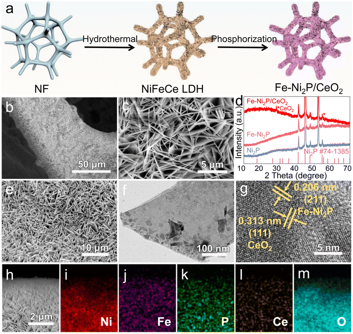
The self-supported Fe-Ni2P/CeO2 nanosheet arrays on the NF substrate were obtained by hydrothermal and phosphorization reactions, as shown in Fig. 1a. Firstly, the NiFeCe hydroxide precursor was uniformly grown on the surface of NF; the resulting X-ray diffraction (XRD) pattern (Fig. S1†) exhibits several characteristic peaks of the layered double hydroxide (NiFeCe LDH).37The morphology and structure of the NiFeCe LDH precursor were analyzed using scanning electron microscopy (SEM), and it was found to be composed of a large number of interconnected nanosheets (Fig. 1b and c). After the phosphorization treatment, we obtained Fe-Ni2P/CeO2 without other impurities as verified via XRD analysis (Fig. 1d). The characteristic peaks at 28.5° and 56.3° and at 40.7°, 47.4°, 54.3° were indexed to the (111) and (311) planes of CeO2 (JCPDS no. 34-0394) and the (111), (210), and (300) crystalline planes of Ni2P (JCPDS no. 74-1385), which correspond to Ni2P and Fe-Ni2P samples, suggesting the formation of Fe-Ni2P/CeO2. Moreover, it can be observed that the Fe-Ni2P/CeO2 retains the nanosheet-like morphology of NiFeCe LDH distributed throughout the NF skeleton (Fig. 1e and S2†), which is similar to that of Ni2P (Fig. S3a†) and Fe-Ni2P (Fig. S3b†), which is beneficial for exposing abundant active sites and providing fast electrolyte transport. For detailed analysis of the microstructure, transmission electron microscopy (TEM) measurement was carried out, and the nanosheet-like structure of Fe-Ni2P/CeO2 can also be seen (Fig. 1f), consistent with SEM results. In Fig. 1g, the high-resolution TEM (HRTEM) image exhibits two distinct lattice fringes with interplanar spacings of 0.206 and 0.313 nm, which were assigned to the (201) and (111) planes of Fe-Ni2P and CeO2, revealing the successful construction of the heterostructure. The elemental composition and distribution of Fe-Ni2P/CeO2 were studied. In Fig. 1h–m, the SEM and corresponding elemental mapping images indicate that the Fe-Ni2P/CeO2 is comprised of the elements Ni, Fe, P, Ce and O, which are homogeneously dispersed over the entire nanosheets.
The chemical status and electronic effects of Ni2P, Fe-Ni2P and Fe-Ni2P/CeO2 were identified using X-ray photoelectron spectroscopy (XPS). As shown in Fig. 2a, the Ni 2p spectrum of Ni2P has two pairs of typical spin–orbit peaks centered at 854.3 and 855.5 eV and at 872.4 and 873.4 eV, corresponding to Ni 2p3/2 and Ni 2p1/2.38 The peaks located at 861.8 and 880.0 eV are assigned as satellite peaks. Noteworthily, the Ni 2p spectrum of Fe-Ni2P (Fig. 2a) shows a positive shift of 0.4 eV compared with Ni2P, indicating that the introduction of Fe can modify the electronic structure of Ni2P. After coupling CeO2, the Ni 2p peaks of Fe-Ni2P/CeO2 shift to a more positive binding energy of 0.3 eV, suggesting further optimization of the electronic structure of Fe-Ni2P and strong electronic interaction between Fe-Ni2P and CeO2, which are beneficial to boost catalytic performances.39 Similar to the Ni 2p spectrum, the Fe 2p spectrum of Fe-Ni2P (Fig. 2b) can be fitted to two Fe doublets, with the peaks at 709.9 and 712.9 eV belonging to Fe 2p3/2 and the peaks at 722.8 and 725.7 eV corresponding to Fe 2p1/2. The signals of satellite peaks at 717.7 at and 732.3 eV can be observed. After decoration with CeO2, the Fe 2p peaks of Fe-Ni2P/CeO2 display a redshift of 0.4 eV compared to those of Fe-Ni2P, proving the existence of a coupling effect and electronic transfer between Fe-Ni2P and CeO2.40 In Fig. 2c, the peaks of P 2p at 128.9 and 129.7 eV are assigned to spin-splitting P 2p3/2 and P 2p1/2, indicating phosphide formation. The presence of P–O bonds (133.8 eV) is observed, probably because of the surface oxidation of phosphide exposed to air.41 In the Ce 3d spectrum (Fig. 2d), Ce 3d5/2 and 3d3/2 peaks can be observed.
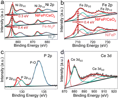 | ||
| Fig. 2 (a) Ni 2p spectra of Ni2P, Fe-Ni2P and Fe-Ni2P/CeO2. (b) Fe 2p spectra of Fe-Ni2P and Fe-Ni2P/CeO2. (c) P 2p and (d) Ce 3d spectra of Fe-Ni2P/CeO2. | ||
Electrochemical performance of Fe-Ni2P/CeO2
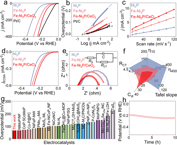
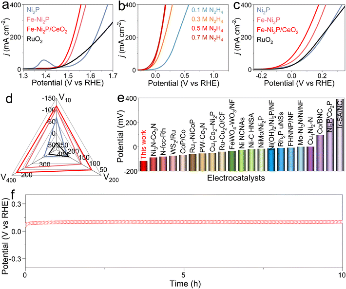
To explore the effect of Fe doping and CeO2 coupling on catalytic performance, the catalytic HER, OER and HzOR performances of Fe-Ni2P/CeO2 were evaluated in alkaline seawater, and comparative experiments for Ni2P, Fe-Ni2P and commercial Pt/C were are also conducted. Fig. 3a displays the HER polarization curves of Ni2P, Fe-Ni2P, Fe-Ni2P/CeO2 and Pt/C, and Pt/C possesses exceptional HER performance. Ni2P has general HER activity requiring a high overpotential of 157 mV to deliver 10 mA cm−2. After the introduction of Fe, the overpotential of Fe-Ni2P is reduced to 101 mV to attain the same current compared with Ni2P, indicating the enhanced HER performance of Fe-Ni2P. Inspiringly, the Fe-Ni2P/CeO2 displays an eminent activity with a low overpotential of 67 mV at 10 mA cm−2 (Fig. 3a and f), surpassing those of Ni2P, Fe-Ni2P and most exploited transition metal materials (Fig. 3g and Table S1†). Moreover, the Fe-Ni2P/CeO2 can output large current densities of 200 and 400 mA cm−2 at small overpotentials of 197 and 249 mV, which are lower than those of Ni2P (315 and 379 mV) and Fe-Ni2P (234 and 301 mV). These results indicate that cation Fe doping and CeO2 coupling play crucial roles in the promotion of HER performances. The corresponding HER kinetics were assessed using the Tafel slope derived from the polarization curves.42 The Tafel slope value of Fe-Ni2P/CeO2 (Fig. 3b and f) was calculated to be 53 mV dec−1, which was smaller than those of Ni2P (108 mV dec−1) and Fe-Ni2P (64 mV dec−1), affirming that the introduction of Fe and CeO2 can accelerate the HER kinetics and that the HER process of Fe-Ni2P/CeO2 follows a Volmer–Heyrovsky process. To examine the origin of the high catalytic activities for Fe-Ni2P/CeO2, the double layer capacitance (Cdl) was computed from the related cyclic voltammetry (CV) curves (Fig. S4†) at various scan rates, which reflect the electrochemical surface area (ECSA) because of the proportional relationship.43 In Fig. 3c and f, Fe-Ni2P/CeO2 displays a larger Cdl value (31.4 mF cm−2) than that of Ni2P (11.5 cm−2) and Fe-Ni2P (23.5 cm−2), in agreement with the outstanding activity of Fe-Ni2P/CeO2. The computed ECSA value of Fe-Ni2P/CeO2 (785 cm2) is larger than that of Ni2P (287.5 cm2) and Fe-Ni2P (587.5 cm2), indicating the exposure of plentiful catalytic sites. In Fig. 3d, the ECSA-normalized polarization curves show that Fe-Ni2P/CeO2 possesses high catalytic performance, verifying that the introduction of Fe and CeO2 can boost the intrinsic activities of active sites.44 The charge transfer process of Fe-Ni2P/CeO2 was probed using electrochemical impedance spectroscopy (EIS). As shown in Fig. 3e and f, the Nyquist diagram of Fe-Ni2P/CeO2 has the smallest semicircle radius compared to Ni2P and Fe-Ni2P, and the Fe-Ni2P/CeO2 possesses the lowest charge-transfer resistance (Rct, 3.0 Ω) and fastest electron-transfer capability at the electrode and electrolyte interface in the catalytic reaction compared with Ni2P (4.2 Ω) and Fe-Ni2P (3.7 Ω). We also assessed the HER activity of Fe-Ni2P/CeO2 in neutral seawater. Fe-Ni2P/CeO2 was found to possess high faradaic efficiency by comparing the amount of gas actually produced with the theoretical gas amount (Fig. S5†), indicating that the catalytic current is derived entirely from the intended catalytic reaction. In Fig. S6a,† it is shown that Fe-Ni2P/CeO2 exhibits good catalytic performance with a small overpotential of 161 mV at 10 mA cm−2 in 1.0 M PBS buffered seawater solution. The catalytic durability of Fe-Ni2P/CeO2 is a vital criterion to evaluate its commercialization in seawater. As shown in Fig. 3h and S6b,† the v–t curves of Fe-Ni2P/CeO2 indicate that the needed potential does not increase significantly at a constant high current density of 200 mA cm−2 during continuous measurement for 10 h, indicating no evident catalytic activity loss and outstanding stability in alkaline and neutral seawater. After the test, the phase, morphology and valence states were analyzed. The XRD (Fig. S7†) and SEM images (Fig. S8†) show that the phase and nanosheet arrays of Fe-Ni2P/CeO2 are well maintained, and the corresponding elements Ni, Fe, P, Ce and O are evenly distributed on the surface of the nanosheets (Fig. S9†). As shown in Fig. S10,† the binding energies of Ni 2p, Fe 2p and Ce 3d exhibit no obvious change, and the peak intensity of the P 2p spectrum diminishes, probably because P was partially dissolved in the electrolyte during long-term operation.45Subsequently, the OER and HzOR activities of Ni2P, Fe-Ni2P, Fe-Ni2P/CeO2 and RuO2 were investigated in seawater media with and without N2H4. For the OER, Ni2P possesses the poorest activity (Fig. 4a). After introducing Fe and CeO2, the Fe-Ni2P and Fe-Ni2P/CeO2 display sequentially improved OER performances with low potentials of 1.458 and 1.442 V at 10 mA cm−2, respectively. Even so, the required potentials for Fe-Ni2P/CeO2 at the anode are still high, leading to large voltages for water electrolysis when coupled with cathodic HER. To settle this situation, the thermodynamically favorable HzOR can be employed to substitute OER. In Fig. 4b, the HzOR activities of Fe-Ni2P/CeO2 were tested in 1 M KOH seawater with various N2H4 concentrations. Compared with the OER, the HzOR curves of Fe-Ni2P/CeO2 display a sharply increased oxidation current as the N2H4 concentration is raised from 0 M to 0.1 M. The HzOR performance continues to increase rapidly as the N2H4 concentration is increased to 0.5 M; subsequently, the HzOR performance remains basically unchanged with further increasing the N2H4 concentration from 0.5 to 0.7 M. Thus, the HzOR activities of Ni2P, Fe-Ni2P and RuO2 were tested in 1 M KOH seawater with 0.5 M N2H4. As shown in Fig. 4c and d, the working potential of Fe-Ni2P/CeO2 is as low as −117 mV at 10 mA cm−2, which is lower than those of Ni2P (−67 mV), Fe-Ni2P (−104 mV), and RuO2 (41 mV), revealing the importance of Fe doping and CeO2 decoration. Impressively, Fe-Ni2P/CeO2 requires lower potentials of 85 and 177 mV to realize large current densities of 200 and 400 mA cm−2 compared with Ni2P (202 and 331 mV), Fe-Ni2P (132 and 224 mV), and RuO2 (192 and 357 mV). The HzOR performance of Fe-Ni2P/CeO2 is superior to many reported values (Fig. 4e and Table S2†). It is worth noting that the required HzOR potential of Fe-Ni2P/CeO2 shows no obvious variation based on the v–t curve (Fig. 4f), indicating its remarkable stability and corrosion resistance. After determination of the HzOR stability, the XRD pattern (Fig. S11†) and SEM images (Fig. S12†) reveal that the phase and uniform nanosheet morphology of Fe-Ni2P/CeO2 are well preserved and the elements Ni, Fe, P, Ce and O were distributed over the nanosheets of Fe-Ni2P/CeO2 in the elemental mapping measurement (Fig. S13†). The XPS spectra (Fig. S14†) indicate that the binding energies of the elements Ni, Fe, P, Ce and O are basically unchanged except for the reduced peak intensity of the P 2p spectrum due to the partial dissolution of phosphide at a high oxidation potential. These results suggest that Fe-Ni2P/CeO2 has outstanding corrosion resistance and structural stability, and can be regarded as an active HzOR catalyst in seawater.
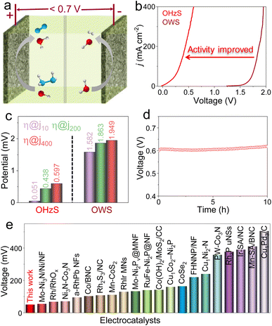
To confirm the application prospects of Fe-Ni2P/CeO2 with remarkable HER, OER, and HzOR properties, two-electrode OWS and OHZS electrolyzers engaging Fe-Ni2P/CeO2 as both cathode and anode were assembled in 1.0 M KOH seawater medium with and without 0.5 M N2H4 (Fig. 5a). As shown in Fig. 5b and c, the overall water splitting (OWS) system displays good catalytic activities with low cell voltages of 1.582, 1.863 and 1.949 V to reach 10, 200 and 400 mA cm−2, which are close to or even smaller than those of many developed catalysts (Fig. S15 and Table S3†). It should be pointed out that the competitive CER may occur and produce corrosive chlorine species at high current densities of 200 and 400 mA cm−2, resulting in catalyst corrosion and environmental hazards. After adding N2H4, the assembled OHZS electrolyzer coupling HzOR with HER not only shows a significant activity enhancement, but also realizes chlorine-free H2 generation at low voltages (Fig. 5b and c). In detail, this electrolyzer requires smaller voltages of 0.051, 0.438 and 0.597 V to deliver the same current densities compared with those needed in the OWS system and many published works (Fig. 5e and Table S4†). Therefore, the hybrid seawater electrolysis by adding the N2H4 to the electrolyte can greatly reduce hydrogen generation voltages and boost energy efficiency. Meanwhile, the Fe-Ni2P/CeO2-based OHZS system possesses excellent long-term stability at a near-industrial current density of 400 mA cm−2 after continuous electrolysis for 10 h (Fig. 5d). After the durability test, the nanosheet-like morphologies of Fe-Ni2P/CeO2 are well retained (Fig. S16 and S17†), indicating its remarkable structural robustness and corrosion resistance. These results prove that the Fe-Ni2P/CeO2 can serve as a promising catalyst to achieve sustainable hydrogen production with high energy-efficiency and chlorine-free products in seawater.
Theoretical analysis
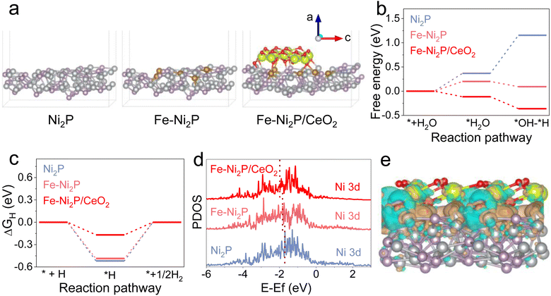
To investigate the possible mechanism for the superior catalytic performance of Fe-Ni2P/CeO2 in depth, density functional theory (DFT) calculations were carried out. The Ni2P, Fe-Ni2P and Fe-Ni2P/CeO2 models are illustrated in Fig. 6a. The H2O dissociation step is known to require a high energy barrier and to dominate the qualitative trend of HER kinetics under alkaline electrolyte.46 The optimized structures for H2O dissociation on the surface of Ni2P, Fe-Ni2P and Fe-Ni2P/CeO2 are displayed in Fig. S18–S20.†Fig. 6b exhibits the calculated H2O dissociation energies on the catalyst surfaces, and Ni2P has a large energy barrier of 0.37 eV for H2O dissociation and an adsorbed hydrogen (H*) generation barrier of 0.78 eV from broken H2O molecular bonds. After Fe doping, the corresponding energy barriers of Fe-Ni2P decreased to 0.20 and −0.11 eV, respectively. The Fe-Ni2P/CeO2 possesses the smallest activation barrier of −0.11 eV and H* formation barrier of −0.25 eV after the coupling of CeO2, implying its rapid and thermodynamically favorable H2O dissociation kinetics to generate H* and support efficient HER. Furthermore, the free energy of H* (ΔGH*) is a pivotal descriptor to assess HER performance, and the ideal ΔGH* should be close to thermoneutrality.47 The optimized H* models on the catalysts are presented in Fig. S14–S16† and the ΔGH* value of Fe-Ni2P/CeO2 (Fig. 6c) is calculated to 0.17 eV, which is closer to thermoneutrality compared to that of Ni2P (0.52 eV) and Fe-Ni2P (0.48 eV), indicating accelerated hydrogen production capacity from the H*. The reduced energy barriers for Fe-Ni2P/CeO2 signify its fast reaction kinetics and high intrinsic catalytic performance, which guarantees an effective HER process and is consistent with experimental results. In Fig. 6d, the projected partial density of states (PDOS) of Ni 3d in Ni2P, Fe-Ni2P and Fe-Ni2P/CeO2 are analyzed, and the corresponding d-band centers are calculated to be −1.05, −1.71, −1.84, and −1.99 eV, respectively. Based on the d-band theory, the downshifted d-band center indicates increased filling of the as-hybridized antibonding orbitals, leading to fluctuation in the interaction between electronic structure and adsorbates on the surface of catalysts.48 Therefore, Fe-Ni2P/CeO2 displays a small activity barrier to form chemical bonds and a low adsorption energy, which is conducive to the desorption of adsorption intermediates. The charge density difference of Fe-Ni2P/CeO2 (Fig. 6e) displays electron localization behavior and charge depletion, indicating the presence of charge transfer process on the interface of Fe-Ni2P and CeO2. These results confirm that the introduction of Fe and modification with CeO2 can synergistically regulate the electronic structure of Ni2P, thus accelerating the intrinsic catalytic kinetics of Fe-Ni2P/CeO2.Conclusions
In summary, Fe-Ni2P/CeO2 nanosheet arrays were successfully constructed as a bifunctional catalyst to obtain energy-saving hydrogen generation by coupling HER with HzOR in alkaline seawater. The as-synthesized Fe-Ni2P/CeO2 reveals excellent catalytic performances toward the HER and HzOR due to the synergistic effect of Fe doping and CeO2 coupling. Impressively, the integrated Fe-Ni2P/CeO2 couple in a two-electrode OHzS electrolyzer delivers small cell voltages of 0.051 and 0.597 V to attain 10 and 400 mA cm−2 and good stability at a large industrial current density of 400 mA cm−2 with avoidable chlorine electrochemistry. The DFT calculations offer a theoretical analysis of the splendid catalytic performances of Fe-Ni2P/CeO2, in which the Fe doping and heterointerfaces between Fe-Ni2P and CeO2 can effectively modify the electronic structure and reduce the reaction barrier.Data availability
The relevant experimental and characterization data are available in the article and the ESI.†Author contributions
Rui-Qing Li: conceptualization, formal analysis, writing – review & editing. Songyun Guo: data curation. Xiaojun Wang: formal analysis. Xiaoyu Wan: data curation, formal analysis. Shuxiang Xie: investigation. Yu Liu: formal analysis. Changming Wang: investigation. Guangyu Zhang: methodology. Jun Cao: software. Jiamu Dai: formal analysis. Mingzheng Ge; methodology. Wei Zhang: conceptualization, writing – review & editing.Conflicts of interest
There are no conflicts to declare.Acknowledgements
This work is financially supported by the National Natural Science Foundation of China (No. 22302103), the Natural Science Foundation of Jiangsu Province (No. BK20230619), the Natural Science Foundation of the Jiangsu Higher Education Institutions of China (No. 23KJB540003) and the Science Research Program of Nantong University (No. 03083110).Notes and references
- J. Turner, Nature, 2004, 305, 972 CAS.
- M. Chatenet, B. Pollet, D. Dekel, F. Dionigi, J. Deseure, P. Millet, R. Braatz, M. Bazant, M. Eikerling, I. Staffell, P. Balcombe, Y. Shao-Horn and H. Schäfer, Chem. Soc. Rev., 2022, 51, 4583 RSC.
- Y. Zuo, S. Bellani, G. Saleh, M. Ferri, D. Shinde, M. Zappia, J. Buha, R. Brescia, M. Prato, R. Pascazio, A. Annamalai, D. Souza, L. Trizio, I. Infante, F. Bonaccorso and L. Manna, J. Am. Chem. Soc., 2023, 145, 21419 CrossRef CAS PubMed.
- X. Deng, X. Zheng, Z. Gong, W. Tan and X. Pei, Chin. J. Rare Met., 2023, 47, 43 Search PubMed.
- Z. He, C. Zhang, S. Guo, P. Xu, Y. Ji, S. Luo, X. Qi, Y. Liu, N. Cheng, S. Dou, Y. Wang and B. Zhang, Chem. Sci., 2024, 15, 1123 RSC.
- H. Liu, W. Shen, H. Jin, J. Xu, P. Xi, J. Dong, Y. Zheng and S. Qiao, Angew. Chem., Int. Ed., 2023, 62, e2023116 Search PubMed.
- J. Chang, G. Wang, Z. Yang, B. Li, Q. Wang, R. Kuliiev, N. Orlovskaya, M. Gu, Y. Du, G. Wang and Y. Yang, Adv. Mater., 2021, 33, 2101425 CrossRef CAS PubMed.
- Q. Liu, Z. Yan, J. Gao, H. Fan, M. Li and E. Wang, Chem. Sci., 2023, 14, 11830 RSC.
- X. Liu, Y. Jiang, J. Huang, W. Zhong, B. He, P. Jin and Y. Chen, Carbon Energy, 2023, 5, e367 CrossRef CAS.
- J. Chi, L. Guo, J. Mao, T. Cui, J. Zhu, Y. Xia, J. Lai and L. Wang, Adv. Funct. Mater., 2023, 33, 2300625 CrossRef CAS.
- B. Sang, Y. Liu, X. Wan, S. Xie, G. Zhang, M. Ge, J. Dai, W. Zhang and R. Li, Chem. Commun., 2023, 59, 8743 RSC.
- W. Wang, X. Yu, H. He, Y. Wang, Y. Li, L. Deng and Y. Liu, Chem. Eng. J., 2023, 465, 142865 CrossRef CAS.
- Z. Wang, Q. Hong, X. Wang, H. Huang, Y. Chen and S. Li, Acta Phys.–Chim. Sin., 2023, 39, 2303028 Search PubMed.
- R. Li, S. Zeng, B. Sang, C. Xue, K. Qu, Y. Zhang, W. Zhang, G. Zhang, X. Liu, J. Deng, O. Fontaine and Y. Zhu, Nano Res., 2023, 16, 2543 CrossRef CAS.
- Y. Zhu, J. Zhang, Q. Qian, Y. Li, Z. Li, Y. Liu, C. Xiao, G. Zhang and Y. Xie, Angew. Chem., Int. Ed., 2022, 61, e202113082 CrossRef CAS PubMed.
- J. Kong, J. Zheng, H. Wu, C. Wan, M. Ye and L. Xu, Chin. J. Rare Met., 2023, 47, 797 Search PubMed.
- Y. Yang, X. Li, G. Liu, H. Liu, Y. Shi, C. Ye, Z. Fang, M. Ye and J. Shen, Adv. Mater., 2023, 36, 2307979 CrossRef.
- H. Wang, M. Sun, J. Ren and Z. Yuan, Adv. Energy Mater., 2023, 13, 2203568 CrossRef CAS.
- X. Liu, J. Chi, H. Mao and L. Wang, Adv. Energy Mater., 2023, 13, 2301438 CrossRef CAS.
- Y. Zhang, R. Yan, X. Xu, C. He, M. Zhou, Z. Zeng, T. Ma, M. Wang and S. Li, Adv. Funct. Mater., 2023, 34, 2308813 CrossRef.
- Z. Ge, Y. Ding, T. Wang, F. Shi, P. Jin, P. Chen, B. He, S. Yin and Y. Chen, J. Energy Chem., 2023, 77, 209 CrossRef CAS.
- R. Li, X. Wan, B. Chen, R. Cao, Q. Ji, J. Deng, K. Qu, X. Wang and Y. Zhu, Chem. Eng. J., 2021, 409, 128240 CrossRef CAS.
- R. Li, C. Wang, S. Xie, T. Hang, X. Wan, J. Zeng and W. Zhang, Chem. Commun., 2023, 59, 11512 RSC.
- X. Zhang, D. Wu, X. Liu, Y. Qiu, Z. Liu, H. Xie, J. Duan and B. Hou, Appl. Catal., B, 2023, 330, 122594 CrossRef CAS.
- R. Li, B. Wang, T. Gao, R. Zhang, C. Xu, X. Jiang, J. Zeng, Y. Bando, P. Hu, Y. Li and X. Wang, Nano Energy, 2019, 58, 870 CrossRef CAS.
- H. Yang, P. Guo, R. Wang, Z. Chen, H. Xu, H. Pan, D. Sun, F. Fang and R. Wu, Adv. Mater., 2022, 34, 2107548 CrossRef CAS PubMed.
- K. Zhang, G. Zhang, Q. Ji, J. Qu and H. Liu, Nano-Micro Lett., 2020, 12, 154 CrossRef CAS PubMed.
- P. Bodhankar, P. Sarawade, P. Kumar, A. Vinu, A. Kulkarni, C. Lokhande and D. Dhawale, Small, 2023, 18, 2107572 CrossRef PubMed.
- B. Sang, Y. Liu, X. Wan, S. Xie, G. Zhang, M. Ge, J. Dai, W. Zhang and R. Li, Chem. Commun., 2023, 59, 8743 RSC.
- S. Chu, W. Chen, G. Chen, J. Huang, R. Zhang, C. Song, X. Wang, C. Li and K. Ostrikov, Appl. Catal., B, 2019, 243, 537 CrossRef CAS.
- M. Ning, Y. Wang, L. Wu, L. Yang, Z. Chen, S. Song, Y. Yao, J. Bao, S. Chen and Z. Ren, Nano-Micro Lett., 2023, 15, 157 CrossRef CAS PubMed.
- Q. Wang, R. He, F. Yang, X. Tian, H. Sui and L. Feng, Chem. Eng. J., 2023, 456, 141056 CrossRef CAS.
- Y. Liu, J. Zhang, Y. Li, Q. Qian, Z. Li, Y. Zhu and G. Zhang, Nat. Commun., 2020, 11, 1853 CrossRef CAS PubMed.
- C. Li, M. Chen, Y. Xie, H. Wang and L. Jia, J. Colloid Interface Sci., 2023, 636, 103 CrossRef CAS PubMed.
- S. Meng, M. Sun, P. Zhang, C. Zhou, C. He, H. Zhang, Y. Liu, Z. Xiong, P. Zhou and B. Lai, Environ. Sci. Technol., 2023, 57, 12534 CrossRef CAS PubMed.
- C. Yang, Y. Lu, L. Zhang, Z. Kong, T. Yang, L. Tao, Y. Zou and S. Wang, Small Struct., 2021, 2, 2100058 CrossRef CAS.
- L. Wen, X. Zhang, J. Liu, X. Li, C. Xing, X. Lyu, W. Cai, W. Wang and Y. Li, Small, 2019, 15, 1902373 CrossRef PubMed.
- S. Lee, L. Bai and X. Hu, Angew. Chem., Int. Ed., 2020, 132, 8149 CrossRef.
- H. Sun, C. Tian, G. Fan, J. Qi, Z. Liu, Z. Yan, F. Cheng, J. Chen, C. Li and M. Du, Adv. Funct. Mater., 2020, 30, 1910596 CrossRef CAS.
- P. Zhou, G. Hai, G. Zhao, R. Li, X. Huang, Y. Lu and G. Wang, Appl. Catal., B, 2023, 325, 122364 CrossRef CAS.
- J. Ren, Y. Wang, L. Chen, L. Gao and W. Tian, Chem. Eng. J., 2020, 389, 124408 CrossRef CAS.
- Q. He, Y. Zhou, H. Shou, X. Wang, P. Zhang, W. Xu, S. Qiao, C. Wu, H. Liu, D. Liu, S. Chen, R. Long, Z. Qi, X. Wu and L. Song, Adv. Mater., 2022, 34, 2110604 CrossRef CAS PubMed.
- X. Zhao, K. Tang, C. Lee, C. Du, H. Yu, X. Wang, W. Qi, Q. Ye and Q. Yan, Small, 2022, 18, 2107541 CrossRef CAS PubMed.
- M. Luo, J. Yang, X. Li, M. Eguchi, Y. Yamauchi and Z. Wang, Chem. Sci., 2023, 14, 3400 RSC.
- S. Lu, C. Cheng, Y. Shi, Y. Wu, Z. Zhang and B. Zhang, Proc. Natl. Acad. Sci. U. S. A., 2023, 120, e2300549120 CrossRef CAS PubMed.
- J. Li, J. Stenlid, T. Ludwig, P. Lamoureux and F. Abild-Pedersen, J. Am. Chem. Soc., 2021, 143, 19341 CrossRef CAS PubMed.
- S. Zhang, C. Tan, R. Yan, X. Zou, F. Hu, Y. Mi, C. Yan and S. Zhao, Angew. Chem., Int. Ed., 2023, 62, e2023027 Search PubMed.
- Z. Wang, C. Zhu, H. Tan, J. Liu, L. Xu, Y. Zhang, Y. Liu, X. Zou, Z. Liu and X. Lu, Adv. Funct. Mater., 2021, 31, 2104735 CrossRef CAS.
Footnote |
| † Electronic supplementary information (ESI) available. See DOI: https://doi.org/10.1039/d4sc01160k |
| This journal is © The Royal Society of Chemistry 2024 |

