
 Open Access Article
 This Open Access Article is licensed under a Creative Commons Attribution-Non Commercial 3.0 Unported Licence
How the AI-assisted discovery and synthesis of a ternary oxide highlights capability gaps in materials science†
Joseph H.
Montoya‡
 *a,
Carolyn
Grimley‡
b,
Muratahan
Aykol
a,
Colin
Ophus
c,
Hadas
Sternlicht
cd,
Benjamin H.
Savitzky
c,
Andrew M.
Minor
cd,
Steven B.
Torrisi
a,
Jackson
Goedjen
e,
Ching-Chang
Chung
b,
Andrew H.
Comstock
e and
Shijing
Sun
a
*a,
Carolyn
Grimley‡
b,
Muratahan
Aykol
a,
Colin
Ophus
c,
Hadas
Sternlicht
cd,
Benjamin H.
Savitzky
c,
Andrew M.
Minor
cd,
Steven B.
Torrisi
a,
Jackson
Goedjen
e,
Ching-Chang
Chung
b,
Andrew H.
Comstock
e and
Shijing
Sun
a
aToyota Research Institute, Energy and Materials Division, Accelerated Materials Design and Discovery, USA. E-mail: joseph.montoya@tri.global
bLucideon, USA
cNational Center for Electron Microscopy (NCEM), Molecular Foundry, Lawrence Berkeley Lab, USA
dDepartment of Materials Science and Engineering, University of California, Berkeley, USA
eNorth Carolina State University, Department of Physics, USA
First published on 7th March 2024
Abstract
Exploratory synthesis has been the main generator of new inorganic materials for decades. However, our Edisonian and bias-prone processes of synthetic exploration alone are no longer sufficient in an age that demands rapid advances in materials development. In this work, we demonstrate an end-to-end attempt towards systematic, computer-aided discovery and laboratory synthesis of inorganic crystalline compounds as a modern alternative to purely exploratory synthesis. Our approach initializes materials discovery campaigns by autonomously mapping the synthetic feasibility of a chemical system using density functional theory with AI feedback. Following expert-driven down-selection of newly generated phases, we use solid-state synthesis and in situ characterization via hot-stage X-ray diffraction in order to realize new ternary oxide phases experimentally. We applied this strategy in six ternary transition-metal oxide chemistries previously considered well-explored, one of which culminated in the discovery of two novel phases of calcium ruthenates. Detailed characterization using room temperature X-ray powder diffraction, 4D-STEM and SQUID measurements identifies the structure and composition and confirms distinct properties, including distinct defect concentrations, of one of the new phases formed in our experimental campaigns. While the discovery of a new material guided by AI and DFT theory represents a milestone, our procedure and results also highlight a number of critical gaps in the process that can inform future efforts towards the improvement of AI-coupled methodologies.
Introduction
Materials discovery is critical to the development of new technologies, and new materials are particularly relevant to advancing energy technologies like batteries and fuel cells to mitigate pressing global challenges such as climate change. Modern materials scientists are increasingly using simulation to elucidate structure–property relationships of inorganic compounds.1,2 Density functional theory (DFT) is a particularly popular tool that allows practitioners to predict materials properties by approximately solving the ground-state electron density of inorganic crystals.3Interest in artificial intelligence for both optimization and prediction of materials properties has also surged in recent years, resulting in a plethora of open-source4–6 and commercial7–9 tools that allow users to design materials in the simulation environment with faster property prediction than ever before. With the increasing automation of DFT simulation from high-throughput databases10–13 and adoption of active learning using AI tools, autonomous simulation platforms which use feedback from AI to choose new simulations based on functionality or synthesizability have emerged.14–16
However, realizing the promise of simulation-supported and AI-guided materials discovery still requires translating the advice of such autonomous platforms into the real world, and materials in the real world possess complexity which is not completely accounted for in simulations or in the AI predictions of simulated properties. This is particularly true in the case of inorganic materials. For organic molecules, while the general problem of fully automated, AI-powered synthesis is unsolved, theories and strategies for exploratory synthesis which were well-developed prior to recent advances in AI have helped facilitate the actual making of AI-predicted molecules.17–19 For inorganic solids, however, synthesis lacks even a basic, community-adopted predictive framework, and almost always represents the rate-limiting step in getting real-world feedback into AI and DFT-driven discovery processes. Given this, we must begin to systematically explore the interface of virtual discovery technologies and real discovery processes, particularly for inorganic materials, in order to fully realize the potential of autonomous DFT.20
For this purpose, we conducted a series of experimental materials discovery campaigns based on the predictions of an autonomous virtual materials discovery system named Computational Autonomy for Materials Discovery (CAMD). CAMD has generated a wide variety of stable and metastable crystal structures in various chemical systems,21 but we focused on our experimental discovery campaigns on ternary oxides, an important class of functional materials that were previously considered well-explored by domain experts.22 Our focus was motivated by domain expertise in oxide precursor handling and synthesis, but we also identified a decline of new reports of ternary oxides in the past two decades from the ICSD23 (see Fig. S1† for a summary of historical discoveries). Thus, discovering a new ternary oxide represents a challenge which, if completed, would demonstrate the power of AI and simulation to assist scientists in synthesizing unexpected new phases. In this manuscript, we describe campaigns in six ternary oxide chemical systems (distinct combinations of elements) proposed to have stable or metastable compounds predicted by AI-guided DFT simulations which ultimately culminated in two newly discovered phases of calcium ruthenate.
While such discoveries, along with similar AI and simulation-guided materials discoveries,24–27 can be described as milestones in the practice of materials science, an honest retrospective on our results suggests that there are still significant gaps to overcome in order to improve on the AI-guided materials discovery which has happened previously in the materials science field. As such, we accompany our results with a discussion of the implications of the limited success, and many failures, of our materials discovery process. In summary, our perspective is that AI, while certainly having an impact on our process, has not yet truly accelerated it relative to what might be expected of a “normal” materials discovery effort, and will require gains in assisted synthesis and characterization before such acceleration can be realized.
Workflow
The workflow for AI-assisted discovery of new materials is outlined in Fig. 1, and includes components of autonomous simulation, downselection and targeted synthesis of predicted compounds, and phase isolation and characterization, which are each detailed in the following sections.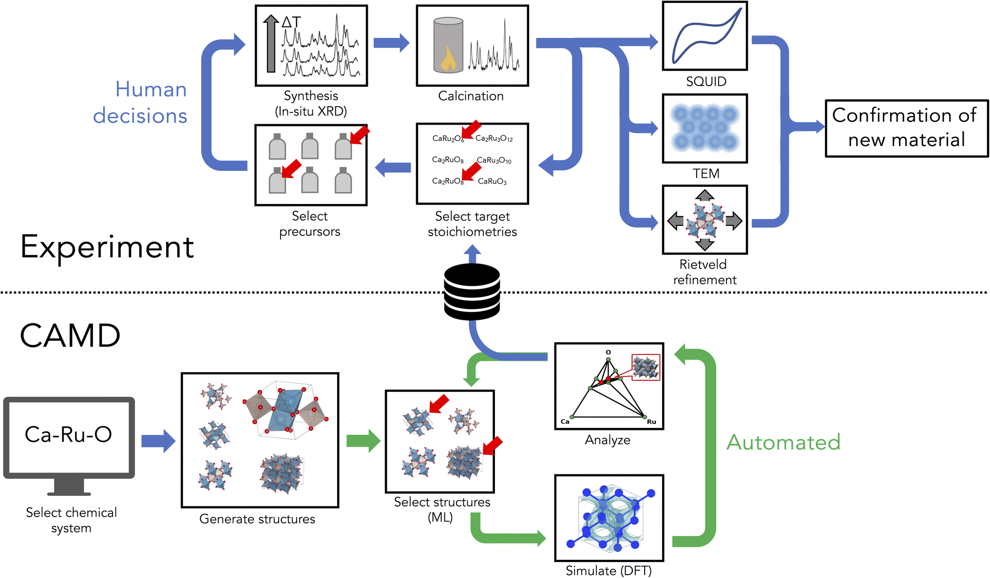 | ||
| Fig. 1 An integrated autonomous simulation and human experimental workflow showing computer-aided discovery and experimental feedback to downselect candidate systems. Green arrows indicate the portion of the workflow which is automated, i.e. the virtual crystal discovery process performed by CAMD, while the blue arrows indicate human workflows, including selection of chemical systems to be explored by CAMD and all of the experimental workflows presented in this work. | ||
Autonomous simulation with CAMD
Computational Autonomy for Materials Discovery (CAMD) generated potentially synthesizable phases from queries submitted by chemical systems or sets of constituent elements, as reported in our prior publication.14 CAMD constructs a pool of potential phases from crystal structure prototypes and then performs an adaptive learning procedure by which it acquires new phases predicted to be stable from DFT calculations. The above-mentioned pool of crystal structures is created using structural prototypes similar to those implemented in ref. 28–30 derived from ICSD that consist of distinct sets of (1) anonymous formulas (2) space groups and (3) lists of symmetrically-distinct Wyckoff positions of the associated anonymous elements. For example, the cubic perovskite SrTiO3, has an anonymous formula ABC3, space group number 221 and includes Sr, Ti, O in the Wyckoff sites a, b, c, respectively, and corresponds to the structural prototype as 221_A_a_B_b_C_c. Thus, the candidate pool is derived from every possible substitution from a given set of elements into every ternary prototype, which is also filtered by those formulae which have some charge-neutral oxidation state configuration corresponding to experimentally observed oxidation states of the given constituent elements.In CAMD, AI is implemented in “agents”, which orchestrate the active learning loop, iteratively predicting figures of merit and selecting new experiments according to those predictions. More specifically, in each iteration of the active learning procedure for virtual crystal discovery, CAMD (1) predicts the DFT-computed formation energy and its estimated uncertainty using an AdaBoost regressor (implemented in scikit-learn31) fitted to Voronoi and composition-derived features32 of each candidate crystal structure. Based on those predictions, CAMD (2) acquires crystal structures predicted to have decomposition energies within 0.2 eV above the convex hull of the phase diagram including a weighted uncertainty estimate from standard deviation of the AdaBoost ensemble, prioritizing those with the lowest predicted stabilities. CAMD then (3) performs DFT calculations using the Open Quantum Materials Database (OQMD) calculation workflow as implemented in qmpy (i.e. with a PBE or PBE + U-level structural optimization and corresponding static calculation implemented in VASP). Following this, CAMD returns to step (1) to retrain the aforementioned AdaBoost model in order to select a new batch of crystal structures from the remaining candidates. CAMD iterates this process until a user-specified maximum threshold of iterations is reached or until no new phases are predicted to be stable within the uncertainty threshold. The default CAMD agent was designed by varying machine learning models and acquisition hyperparameters in order to optimize acquisition efficiency, or the number of new, stable or metastable crystal structures acquired per DFT simulation conducted. Further details of the agent selection process are provided in our previous publication about CAMD and its strategy for implementing agents for autonomous virtual crystal discovery14 and the open-source CAMD package on github.33
We note that, since CAMD's first publication in 2020, a number of new approaches to machine and active learning for materials have been developed. Perhaps the most notable advance is the emergence of graph convolutional neural networks as a surrogate model for DFT, which has significantly enhanced prediction accuracy while enabling more elegant back-propagation in re-fitting procedures to continuously acquire results. In addition, data used to initiate CAMD virtual discovery campaigns is derived solely from DFT simulations of ICSD-included compounds, and virtual materials datasets have advanced significantly with the advent of new large datasets for both inorganic materials34,35 and surfaces.36,37 There are also new and different strategies for CAMD's generative step e.g. that make use of diffusion-based models38 and invariant structural interpolation,39 and these methods may exceed CAMD's capability in efficiency and their ability to more exhaustively explore the space of crystal structure candidates for simulation. While a rigorous benchmarking of the underlying AI methods of CAMD and newer methods is outside of the scope of this work, we speculate that novel prediction methods, datasets, and generative algorithms could significantly improve on CAMD as an AI system. Thus, the intent of this work is not to present CAMD as a novel AI system, but rather to explore the interface between an autonomous system for virtual crystal discovery and that of the materials scientist in the real-world laboratory.
In preparation for the experimental discovery campaign described in this work, CAMD autonomously explored 192 ternary oxide (i.e. AxByOz) chemical systems using the procedure outlined above. A database which includes every crystal structure simulated with DFT in CAMD in these oxide chemical systems, including those which were found to be unstable, along with around 1265 other chemical systems, was described in previous work and is available in a corresponding public data repository.14,21,33
Downselection and synthesis of target phases
A workflow was designed to reasonably attempt validation/exploration of each selected composition while limiting the amount of experimental effort focused on any one predicted phase. Six materials systems were selected from the 192 explored by CAMD. A solid-state approach to synthesis was used to limit the number of experimental parameters, combined with in situ hot stage XRD (X-ray powder diffraction) as a screening technique to maximize the ranges of feasible experimental conditions (e.g. the temperature window above which precursors melt) experimental space and capture any metastable phases. Additional heat treatments were performed in order to isolate phases of interest, followed by additional characterization as required.Initially, the six chemical systems were down-selected based on a combination of computational and practical experimental factors. Computational considerations included the number of ground-state and metastable phases predicted by CAMD and the degree of perturbation to the hull. In Fig. 2, the ground-state criteria are shown from the CAMD dataset, highlighting those that were chosen. Information about the number of near-stable (ΔEhull < 0.05 eV per atom) and metastable (ΔEhull < 0.2 eV per atom) phases predicted by CAMD is provided in the supplement (Fig. S2†). For example, Ag–Li–O, Ca–Ru–O, Li–Ru–O, and Ag–Ca–O were among the highest ranked by number of metastable phases. Ca–Ru–O and Li–Ru–O had the highest number of near-stable phases, and Mg–Ru–O had three predicted ground states with fewer metastable phases, which provided for a promising, but distinct case in terms of computationally viable structures.
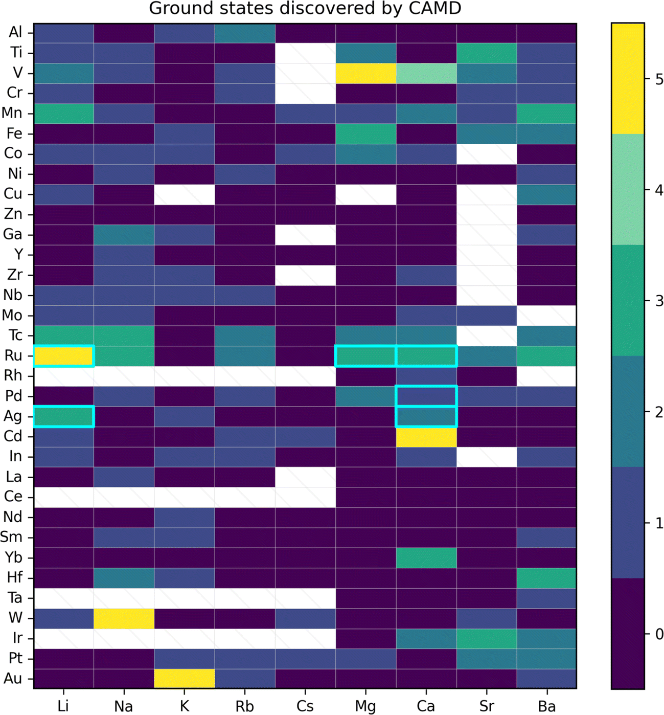 | ||
| Fig. 2 Ternary oxide systems tested in CAMD prior to experimental synthesis indicating the number of phases identified as ground states (ΔEhull < 0.001). Individual rectangles on the grid correspond to ternary oxide systems with combinations of elements on the horizontal and vertical axis labels, e.g. Al–Li–O in the upper-rightmost corner. These rectangles are colored by the number of new ground state crystals identified in CAMD, e.g. 1 new ground state phase in Al–Li–O. Systems which were down-selected for attempted real-world synthesis are highlighted with cyan outlines, and also shown in Table 1. White rectangles indicate that a CAMD campaign was not conducted in the corresponding chemical system. | ||
Practical experimental considerations included the amount of historical exploration in a given system, the commonality of the predicted oxidation state under ambient conditions, the likelihood of forming hazardous byproducts, and interest in potential applications in e.g. electrolyzer, electrocatalysis or Li-ion cathodes. In addition to reinforcing the choice of Li–Ru–O, Mg–Ru–O, and Ca–Ru–O, the catalyst application criteria led us to choose one system which was not particularly favorable, Ca–Pd–O, because it contained a common metal in catalysts (Pd). These criteria also helped us eliminate systems which seemed highly favorable from a purely computational perspective, including vanadates like Mg–V–O and Ca–V–O (well-explored, with 19 and 21 unique entries in the ICSD, respectively) and Ca–Cd–O (toxic).
Two compositions from each system, which corresponded to novel ground state compositions predicted in CAMD, were targeted. This choice was made in order to have multiple trials of each chemical system while also conforming to budget constraints.
Next, powder mixtures of oxides or carbonates containing the constituent cations of the desired ternary oxide were selected for each system. Nanoparticles were used when commercially available in an attempt to reduce kinetic limitations; when unavailable, additional milling was used to reduce particle size prior to mixing. Powders were mixed in stoichiometric quantities for each of the twelve compositions of interest using high energy milling in a zirconia jar with zirconia milling media and either deionized water or ethanol, depending on the properties of the powder mixtures. The primary screening experiments were performed by heating each composition separately in air and monitoring the phase transitions via XRD, see Table 1 for the details of each system. There were three goals for each of these experiments: one, to observe the formation of any computationally predicted or previously undiscovered phases; two, to identify the optimal temperature ranges for synthesis in the present experimental setup; and three, to benchmark the solid-state reaction by the attainment of “control” phases i.e. known pre-existing phases within the chosen system.
| System | Target stoichiometry | Precursors | Temperature range (°C) | Observed phase(s) |
|---|---|---|---|---|
| Ca–Ag–O | CaAg3O4 | CaCO3 + AgO | 25–900 | Ag2O, Ag, CaO |
| Ca3AgO4 | Ag2O, Ag, CaO | |||
| Li–Ag–O | LiAg3O4 | Li2CO3 + Ag2CO3 | 25–600 | Ag2O, Ag |
| LiAgO2 | Ag2O, Ag | |||
| Ca–Pd–O | Ca(PdO2)3 | CaCO3 + PdO | 25–900 | CaPd3O4, Pd |
| CaPdO3 | CaPd3O4, CaO, Pd | |||
| Mg–Ru–O | Mg(RuO3)2 | MgCO3 + RuO2 | 25–1100 | MgO |
| MgRuO4 | MgO | |||
| Ca–Ru–O | CaRuO4 | CaCO3 + RuO2 | 25–1100 | CaRuO3 |
| Ca3RuO6 | CaRuO3, CaO, LT phase, HT phase | |||
| Li–Ru–O | Li4RuO5 | Li2CO3 + RuO2 | 25–600 | Ru, Li2RuO3 |
| Li5RuO5 | Ru, Li2RuO3 |
Phase isolation and analysis
After the initial screening, additional long-duration heat treatments were performed for each composition. If an unidentifiable phase was observed during the screening, these heat treatments were used to isolate the phase and capture a high-resolution room-temperature X-ray diffraction pattern. If an unidentified phase was not observed, the heat treatment was targeted to test for kinetic limitations. In either case, the thermal decomposition information from the in situ XRD was used to identify favorable temperature ranges. When appropriate, alternate approaches were used to increase the likelihood of reaction, including the use of PIRO,40,41 a solid-state synthesis planning tool based on thermodynamic and nucleation theories, which guided the selection of alternate precursors with a theoretically higher likelihood of targeted phase formation.Based on the screening process, the Ca–Ru–O system was identified as containing multiple phases of interest. Additional work was performed to isolate these phases at room temperature. Heat treatments were performed using a new series of precursors suggested by PIRO, as well as temperatures ranging from 450 to 950 °C, and successive grinding and soaking steps. For these experiments, powders with larger particle sizes were used to improve peak resolution in XRD. High energy mixing in deionized water and hand-grounding with an agate mortar and pestle were applied when appropriate to control the particle sizes. To improve final phase purity, excess CaO was removed by dissolution in deionized water and vacuum filtration. Rietveld refinement was performed to quantify the phase fractions in the samples using GSAS II software. Subsequent characterization included ICP, TEM, EDS mapping, and magnetization measurements.
Results
Phase generation, isolation, and identification
The results of the CAMD campaigns corresponding to downselected chemical systems are shown in Fig. 3, including phase diagrams and sample crystal structures for each chemistry. Each system possessed at least two predicted ground states and were generally a combination of alkali or alkaline earth metals (excluding beryllium due to safety and cost constraints) with a precious metal. For each system, two ground states were selected as target compositions and are denoted in Table 1. Note that the choices of target compositions affected only the stoichiometry of the starting powder; the selected targets do not preclude the possibility of novel non-stoichiometric phases forming in a mixed region of the phase diagram. Precursors were selected for each system and in situ heat stage powder XRD scans were performed, with the temperature ranges determined to maximize the likelihood of reactions while maintaining solid state reactants. Carbonates were chosen when possible to introduce decomposition events and encourage mixed phase formation. Phases observed in the synthetic screening, along with heating temperature ranges, are summarized in Table 1. XRD patterns of each system can be found in the ESI (Fig. S10†).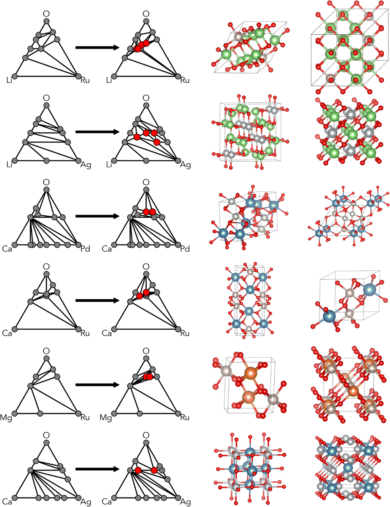 | ||
| Fig. 3 Phase diagrams and selected crystal structures resulting from CAMD campaigns in the six chemical systems chosen for synthesis. Newly identified ground-state compositions are shown in red on the right phase diagram, and two selected corresponding crystal structures are also shown. | ||
One system of particular interest is highlighted in Fig. 4: Ca–Ru–O. Two unidentified phases were observed during the two in situ variable temperature XRD scans. One phase, we refer to in this study as the “low temperature (LT) phase”, is present below ∼950 °C and is most notably characterized by the shift in the 23° peak starting at ∼650 °C. This phase is present in both experiments starting with reactant ratios targeting CaRuO4 and Ca3RuO6 product stoichiometry, respectively, and appears to be associated with a non-stoichiometric Ru content through slow diffusion of Ru forming new Ca–Ru–O structures, as evidenced by the residual intensity of the 28° RuO2 peak. Upon further heating, the residual RuO2 fully reacts into conventional CaRuO3 between 750 and 950 °C in the stoichiometric CaRuO4 targeted mixture. The visible diffraction peak positions of this LT phase indicate a structure similar to the established CaRuO3 perovskite phase, with a higher Ca-content/lower Ru-content likely causing the peak shift, i.e. Ca1+xRuO3+y. Upon cooling down, the peak positions of the LT phase never overlapped with the behavior of the established conventional CaRuO3 positions formed at higher temperatures, indicating that the observed peak shift is structurally based and not a byproduct of thermal lattice expansion.
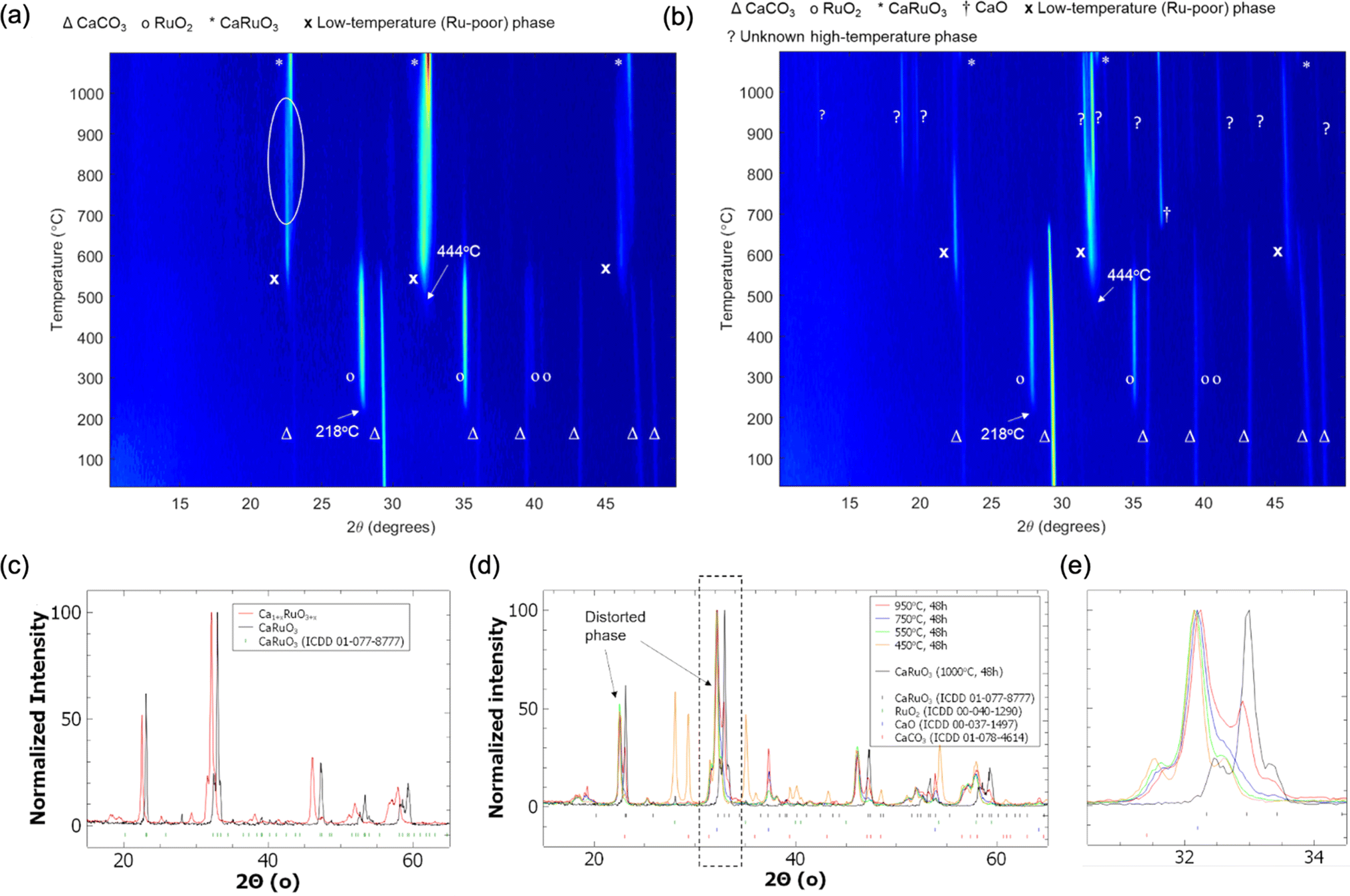 | ||
Fig. 4
In situ XRD patterns for target stoichiometry (a) CaRuO4 (precursor ratios of CaCO3![[thin space (1/6-em)]](https://www.rsc.org/images/entities/char_2009.gif) :RuO2 = 1:1) and (b) Ca3RuO6 (precursor ratios of CaCO3:RuO2 = 3:1). The phase event at 218 °C corresponds to the crystallization of the amorphous RuO2 nanoparticles used in this experiment. The event at 444 °C corresponds to the initial formation of the first mixed phase and the almost total decomposition of the CaCO3 nanoparticles; in (b) excess CaO is produced upon total decomposition. (c) Room-temperature XRD of the isolated LT phase, (d) temperature series depicting the thermal stability window and phase conversion behavior of the LT phase, and (e) enlarged region of the temperature series depicting the decrease and increase in relevant peaks of the LT phase, as discussed in the text. :RuO2 = 1:1) and (b) Ca3RuO6 (precursor ratios of CaCO3:RuO2 = 3:1). The phase event at 218 °C corresponds to the crystallization of the amorphous RuO2 nanoparticles used in this experiment. The event at 444 °C corresponds to the initial formation of the first mixed phase and the almost total decomposition of the CaCO3 nanoparticles; in (b) excess CaO is produced upon total decomposition. (c) Room-temperature XRD of the isolated LT phase, (d) temperature series depicting the thermal stability window and phase conversion behavior of the LT phase, and (e) enlarged region of the temperature series depicting the decrease and increase in relevant peaks of the LT phase, as discussed in the text. | ||
Nevertheless, during the in situ synthesis and characterization, thermal shift in lattice parameters complicates and, in some complex multiphase diffraction patterns, prevents phase identification. We therefore performed additional experiments aiming to isolate the Ca–Ru–O new phases from the in situ observations via quenching and characterized the materials in detail at room temperature. Fig. 4c shows the isolated room temperature X-ray diffraction pattern of the LT phase exhibiting lattice parameters that are different from conventional, stoichiometric CaRuO3. The heat treatments performed to isolate this phase identified a small temperature window around 550 °C, as presented in Fig. 4d, in which sufficient thermal energy was present to form the phase without promoting conversion to conventional CaRuO3; the latter has been observed to be stable at 1000 °C. As shown in Fig. 4e, this conversion is most obviously identified by the intensity decrease of the (112) CaRuO3 peak at 32.96° and the increase in the peak intensity at 33°. The transition was accompanied by a decrease in unincorporated Ca in the form of CaO, as evidenced by the diminishing height of the (200) peak at 37.48°. Further ICP-OES and EDS characterization can be found in Fig. S3,† lending credence to the hypothesis of a new phase with a bulk Ca1+xRuO3+y stoichiometry.
The second unidentified phase, the high temperature (HT) phase, is metastable and appears only in the scan targeting Ca3RuO6 stoichiometry between ∼800 and 1100 °C. The beginning of the phase decomposition can be identified in Fig. 4b at ∼1090 °C; Fig. S9† provides the annealing and cooling data which demonstrate the collapse of the metastable phase into CaRuO3 and excess CaO. This phase appears to progress from the decomposition of the low temperature phase as well as incorporation of additional Ca (as evidenced by the diminished 39° CaO peak intensity). The peak splitting may indicate progression to a low symmetry phase(s), unusual behavior for perovskite systems which typically increase in symmetry with temperature. We also attempted to isolate the HT phase via quenching, and while the phase composition is reproducible, the results still contain multiple phases and are not helpful for further phase identification. More details concerning this high temperature phase can be found in Fig. S4 in ESI.†
Structure and composition characterization
We now focus on detailed structural determination of the new LT phase that was successfully isolated and showed higher stability than the HT phase. Rietveld refinement was performed to identify the space group and the results are shown in Fig. 5 for a tetragonal CAMD prediction, and an orthorhombic CAMD prediction, and three pre-existing calcium ruthenate crystal structures in ICDD. While two new structure prototypes predicted by CAMD (Ca3RuO6 and CaRuO4) were initially used to guide the refinement, we found the LT phase more closely matched crystal structures reported in ICSD with compositions of CaRuO3. Different space groups (i.e. Pnma, Pbnm and I4/mmm) of CaRuO3 were therefore used as starting structures for the refinement. All orthorhombic structures provided equivalently good fits (Rwp ∼ 5%) if lattice strain of 2.3–2.4% was allowed; although the tetragonal prediction shared similar peak positions, the intensity disagreed significantly. Despite the high quality fit with orthorhombic phases, a minor set of peaks remained which indicated the presence of a second phase. This second phase may result from a version of a previously reported calcium-rich rhombohedral structure (Ca2.83RuO4.83),42 included in Fig. 5d. Since all well-fitting diffraction patterns started with an orthorhombic space group, we note that further investigations are required to understand the structural location of the excess Ca and its contribution to the expanded lattice parameter, as discussed below.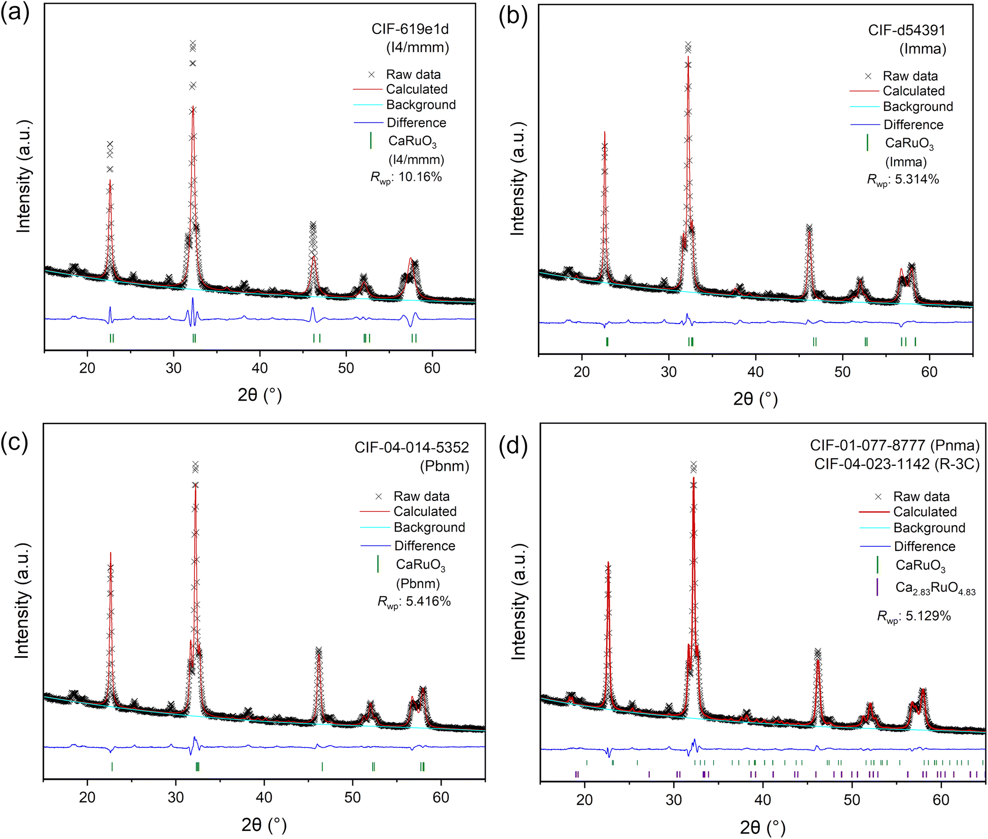 | ||
| Fig. 5 Rietveld refinement results of the LT phase from the crystal structures of two CAMD predicted phases (a, b) and three pre-existing phases (c and d) from the ICDD. | ||
To better understand the complex structure and chemistry of the new phase, scanning transmission electron microscopy (STEM) was used to determine the local structure and composition. In particular, we compare the previously reported orthorhombic CaRuO3 (CIF-01-077-8777) with the LT Ca1+xRuO3+y phase synthesized in this study. Four-dimensional STEM (4D-STEM), energy dispersive spectroscopy (EDS)-STEM and column resolved high angle annular dark field (HAADF)-STEM micrographs were acquired from a focused ion beam (fib) sample prepared from the powder batch of the LT phase. 4D-STEM and EDS-STEM were also acquired from a fib sample prepared from a powder batch of the CaRuO3 control phase used as a standard. EDS maps and 4D-STEM datasets, collected separately and acquired from the same area, were aligned with respect to each other, to allow determination of structure and composition pixel-by-pixel in parallel.
Fig. 6 presents chemical composition analysis of the LT phase synthesized in this study, demonstrating the presence of overlapping porous grains of a LT phase and a non-negligible amount of a calcium oxide secondary phase, using EDS-STEM (Fig. 7a–c) and 4D-STEM (Fig. 7d–j). Scaling between the Ca and Ru EDS intensities (Cliff–Lorimer k-factor) was extracted from the CaRuO3 control sample in order to map the atomic concentration ratio in the LT phase. The results (Fig. 7d–j) indicate a non-homogeneous microstructure. Fig. 7d and i presents an example of an area with significant changes in composition, associated with the presence of crystalline calcium oxide. Virtual images from the Bragg signal in the annulus k = 0.330 ± 0.007 Å−1, the diffraction space length of an observed peak that does not match the ternary phase, reveal crystalline calcium oxide overlapping the most pronounced pocket of elevated Ca content. The composition is strongly dependent on the local microstructure, which includes calcium oxide grains and minor amounts of amorphous phases. Using a scan over a ∼1 μm2 region of comparatively constant composition and no detected scattering from the calcium oxide peak, an atomic Ca/Ru concentration ratio of 1.6 ± 0.2 was estimated (Fig. 7e–j). The determined average composition is consistent with the structure solution, which is a distorted orthorhombic CaRuO3-type crystal structure, associated with the larger radius of Ca2+vs. Ru4+, and the excess Ca content. The EDX/4D-STEM alignment, k-factor calibration, and additional virtual Bragg imaging are shown in Fig. S6 and S7.†
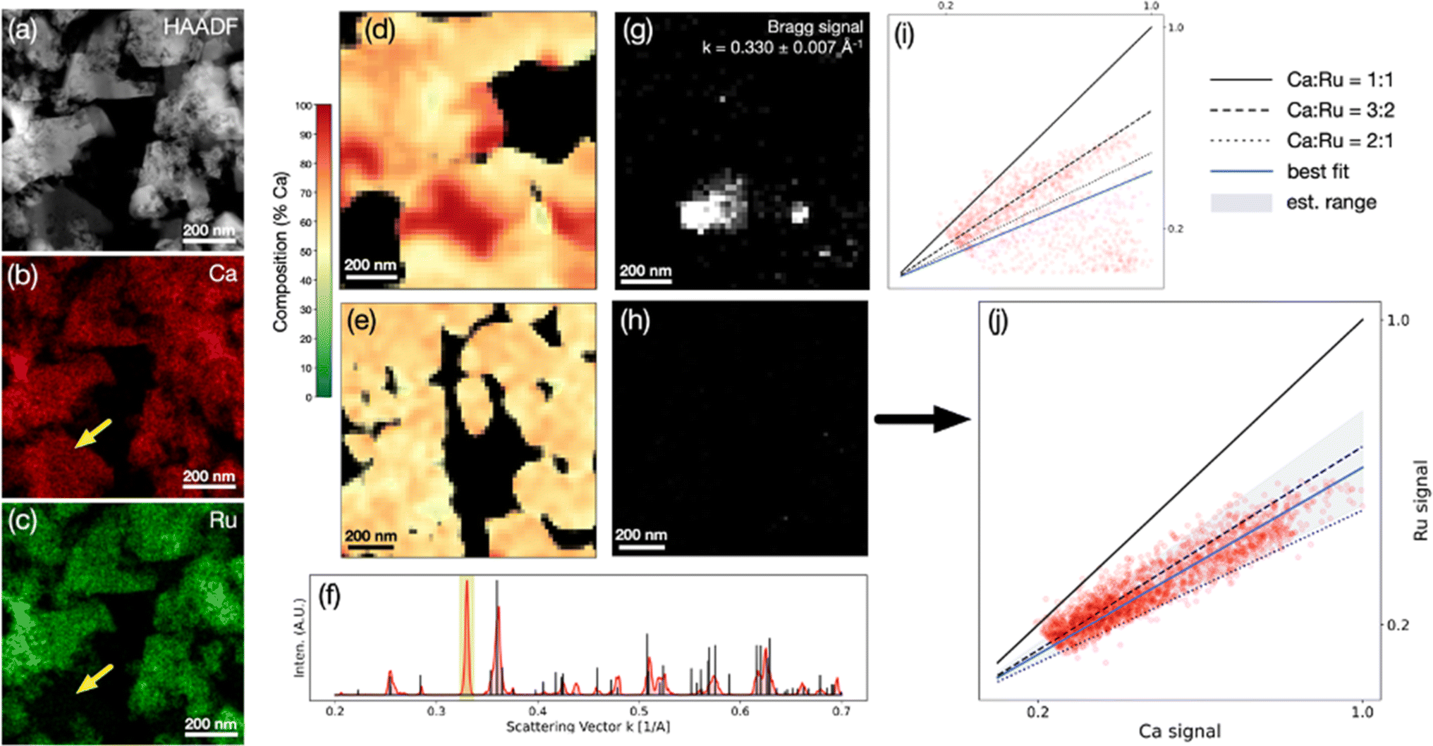 | ||
| Fig. 6 Local chemical composition analysis of the LT phase. (a–c) HAADF, Ca, and Ru signals from an EDS-STEM scan highlighting crystalline calcium oxide (yellow arrows). (d, e) Composition maps (Ca:Ru at% concentration ratio), (f) a Bragg scattering profile presenting experimental data (red), computed Ca–Ru–O peaks (black) and the integration window used to generate virtual images (yellow). (g, h) Virtual images of crystals with scattering inside 0.330 ± 0.007 Å−1 derived from correlative EDS-/4D-STEM. (i, j) Composition scatter plots derived from correlative EDS-/4D-STEM overlaid with Ca:Ru atomic ratios of 1:1, 3:2, and 2:1 (solid, dashed, dotted lines) and best fits (blue lines). In (j) the shaded blue region highlights a ±0.32 window about the 1.63 best fit line. | ||
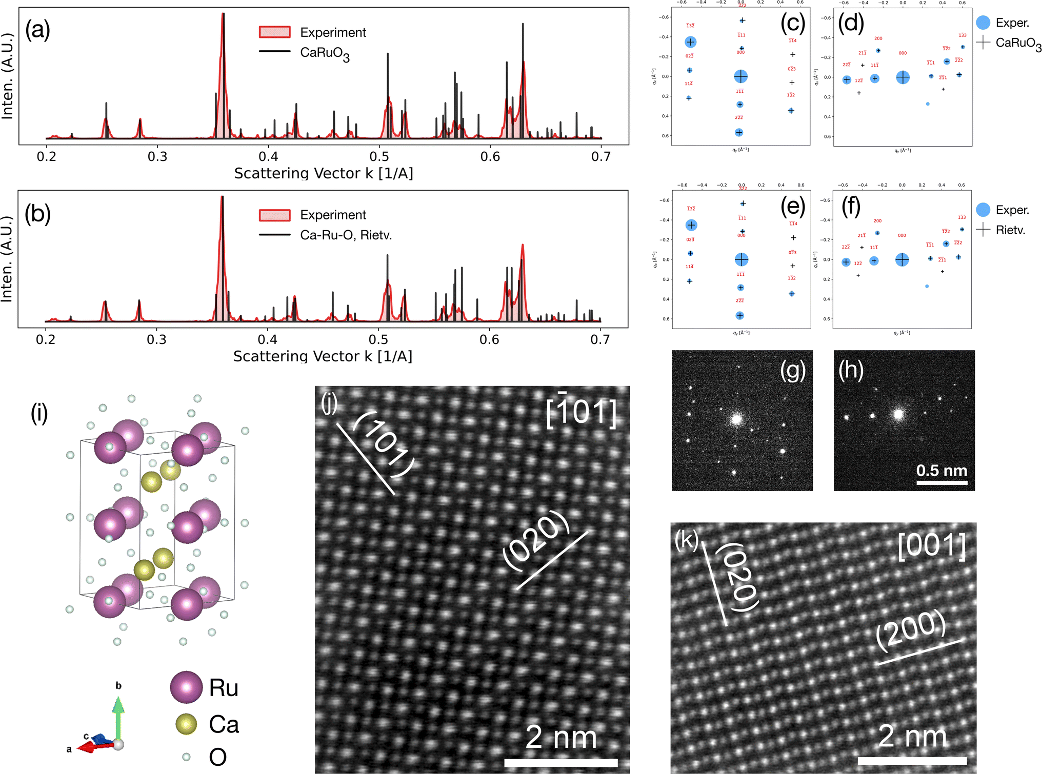 | ||
| Fig. 7 Structural analysis of the LT phase with 4D-STEM and high resolution HAADF-STEM. (a, b) Scattering profiles from the total localized Bragg signal over all 64 × 64 diffraction patterns of a single 4D-STEM scan of the LT phase over a compositionally homogeneous region, overlaid with computed scattering from the conventional orthorhombic CaRuO3 cell expanded isotropically by 2.55% (a) and the Rietveld cell in a Pnma space group (b). (c–h) Experimental and computed Bragg signal matches for selected diffraction patterns for the expanded conventional orthorhombic CaRuO3 (c, d) and X-ray Rietveld refined (e, f) cells, with the associated raw data (g, h). (i) The CaRuO3 structure; note that the atom sizes here are scaled to reflect the Z-contrast intensities of the HAADF data (ZRu = 44, ZCa = 20) rather than the electron radii (rVdWRu = 205 pm, rVdWCa = 231 pm). (j and k) Filtered (average background subtracted) aberration corrected HAADF-STEM micrographs along the [101] and [001] axes. | ||
Fig. 7 presents detailed structural analysis of the LT phase using 4D-STEM and high resolution HAADF-STEM. The results from electron microscopy also show that the LT phase exhibits an orthorhombic cell with a Pnma space group, which has been distorted with respect to a conventional orthorhombic CaRuO3 unit cell, associated with the larger radius of Ca2+vs. Ru4+, and the average measured 1.6 Ca:Ru atomic ratio. The data was compared to calculated scattering from both the X-ray Rietveld refined unit cell determined in this study (fitted with a Pnma space group) and a conventional orthorhombic CaRuO3 unit cell after isotropic expansion of 2.55%. Comparable expansion is introduced to the Rietveld refined cell via the refinement process itself. Radially integrated scattering profiles (a, b) and 2D matches in the diffraction plane (c–h) acquired from a compositionally homogeneous region show good agreement with both structures. This is due to their similarity: both are of the same space group (Pnma), with small changes in the relative atom positions.
Deviations are present in the data, such as a poorly matched minor peak near 0.39 Å−1. These are likely associated with the inherent limitations of each cell: both assume a 1:1 Ca:Ru atomic ratio, omitting necessary structural defects, and the Rietveld cell was refined for the ternary phase despite being extracted from measurements of a two phase powder system. Other possible sources of error include contaminations, secondary phases (including the observed calcium oxide and an amorphous phase detected in small amounts), and structural non-uniformities. Additional examples of 1- and 2-D scattering matches to LT phase and CaRuO3 control samples are presented in Fig. S4 and S5.† High resolution HAADF-STEM imaging (Fig. 6i and k) along the [100] and [110] directions of two different grains of the ternary phase in the LT phase indicates the presence of alternating Ca–Ru planes along (002) planes. This confirms the absence of ordering of defects or stacking faults, suggesting a significant solubility limit of excess of Ca (or high concentration of Ru vacancies) in the CaRuO3-type inorganic framework at the studied conditions, or a kinetic contribution in the form of slow diffusion processes. In the HAADF-STEM micrographs, as for the scattering profiles, the expanded orthorhombic CaRuO3 cells and Rietveld refined cells are not distinguished.
Functional characterization
To further determine whether the synthesized phases of calcium ruthenate are distinct from known materials, we conducted a preliminary characterization of their functionality. Presented herein is a discussion of the magnetic properties of the new phases and how they provide further evidence that the LT calcium ruthenate phase is distinct from known phases.The magnetic behavior of the calcium ruthenate system has been reasonably well-studied due to the interesting range of magnetic behaviors exhibited by ternary ruthenates, and particularly the discovery of superconductivity in Sr2RuO4. Yet the magnetic behavior of CaRuO3 has proven historically complex to categorize. Some papers note irreversibility in the magnetic response of samples which are field-cooled (FC) versus zero-field cooled (ZFC);43,44 at times this behavior has been interpreted as antiferromagnetic45 or described by itinerant ferromagnetism. These works additionally note some small hysteresis in the otherwise classically paramagnetic M-H loops of CaRuO3, although the temperature dependence of the hysteresis differs substantially between polycrystalline and single-crystal samples.43 Furthermore, other studies report ferromagnetism induced by small tensile strains (2–3%)46,47 and doping with e.g. Cr47 and Fe.43,44 Felner et al.44 suggested that CaRuO3 is structurally, and therefore electronically, unstable, and thus easily induced to behave in ferromagnetic or antiferromagnetic ways. The consistent conclusion from this body of literature is that CaRuO3 is on the verge of being magnetically ordered, may possess some ordering at very low temperatures (<5 K), and can be induced to exhibit antiferromagnetic or ferromagnetic coupling fairly readily.43,44,48,49
Given the rich magnetic behavior of CaRuO3 and its dependence on structural distortions, the magnetization of the LT Ca1.6RuO3+y phase and the CaRuO3 control phase was measured as described in the supplement; see Fig. 8. Both measurements exhibited paramagnetic M–H loops in addition to the previously reported irreversibility upon field-cooling. However, this irreversibility occurred at a higher temperature (165 K vs. 90 K) and was of a much larger magnitude in Ca1.6RuO3+y than CaRuO3. While the appearance of irreversibility in CaRuO3 at 90 K is consistent with ceramic CaRuO3 in literature,44 both the magnitude of the transition and the increased temperature of the Ca1.6RuO3+y behavior indicate an enhanced effect relative to the previously discussed reports. Furthermore, while this effect is distinct in magnitude, it does not represent a transition to ferromagnetic behavior. Rather, in the context of the literature discussed above, the most likely interpretation is that the insertion of additional Ca induces an effect on the Ca–O bond similar to that of the strain induced by chemical dopants,46,48 as represented by the lattice expansion discussed earlier, introducing an increased number of weak magnetic moments locally.
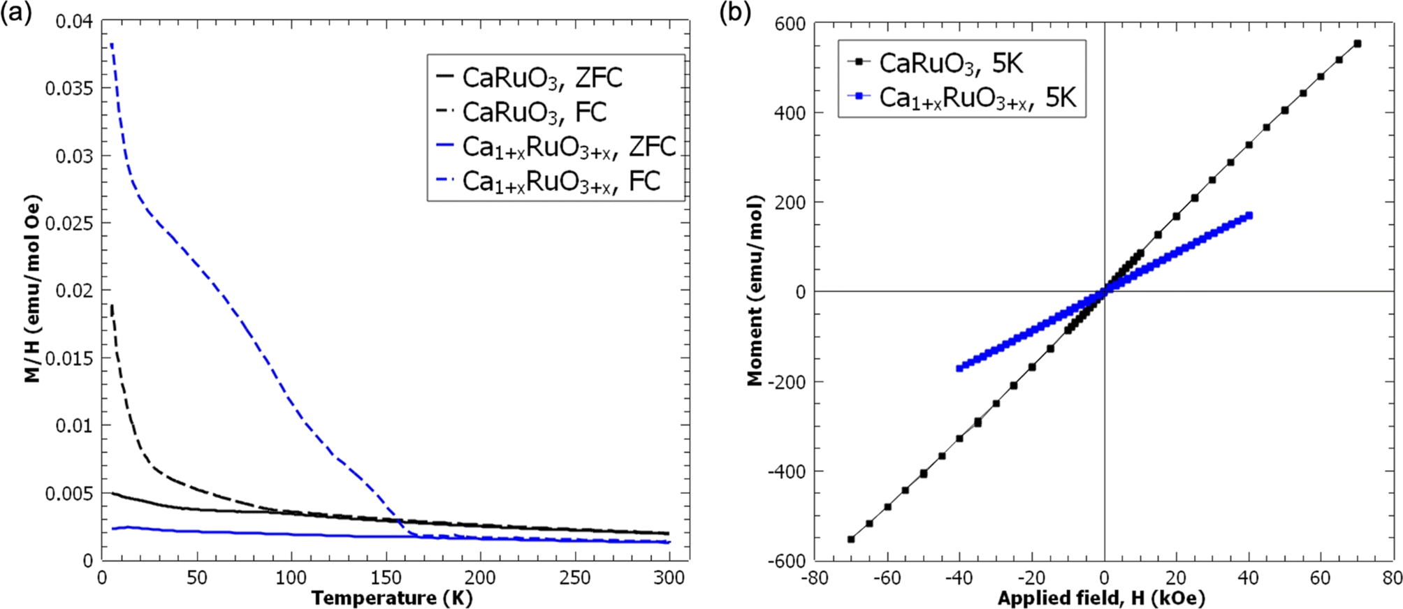 | ||
| Fig. 8 Magnetization measurements of control phase CaRuO3 and the LT phase, Ca1.6RuO3+y (a) versus temperature at 100 Oe and (b) versus applied field at 5 K. | ||
Discussion
Validation of workflow
For the sake of brevity, we do not provide a detailed discourse of each of the attempts at synthesis which resulted in known phases; however, a couple of points are worth discussing. First, it is noteworthy that in three of the systems, “control phases” (that is, previously reported ternary oxides) were observed during the in situ experiments; these include CaPd3O4, CaRuO3, and Li2RuO3. Of the remaining three systems, two did not possess a control phase, as there are no reported ternary oxides in the Mg–Ru–O and Ca–Ag–O systems in the ICSD. For the final system, Li–Ag–O, the control phase LiAg3O2 was observed during follow-up calcination experiments.We refer to these previously reported oxides as control phases because they function to validate the experimental workflow used in this study. If, as CAMD predicted, each of these systems possessed a phase with lower formation energy than the previously reported phases, the system would be expected to form that phase given sufficient energy to overcome the reaction barrier. The formation of these control phases indicates that adequate reaction energy was supplied.
There are multiple practical reasons why the CAMD predictions (along with many other hypothetical materials produced in DFT screening) may not have been observed. Many of the predicted phases required elements to adopt unusual or even previously unobserved oxidation states; in these systems, the precious metal was typically required to adopt a higher value, as in the case of the predicted CaRuO4 structure. The oxides of precious metals in particular tend to destabilize at challenging temperatures; in particular, Ag2O decomposes between 200–300 °C.50 Additional experiments were run in pure oxygen to improve the thermodynamic stability of the oxides; however, full thermodynamic stabilization requires an increase in oxygen partial pressure of several orders of magnitude in the case of many of these materials.51 In principle, phase diagrams and corresponding stabilities in varying oxygen chemical potential environments may be computed using simulation data, but comparing these explicitly to experimental conditions is still challenging. Thus, it is often not done in DFT screening experiments.
Furthermore, there are practical limitations to the accuracy of simulation both in the actual calculations as well as in their transference to the real world. Even when unusual environmental conditions were likely not required (after all, RuO2 is stable up to 1300 °C), the margin of error in the hull calculations means that a predicted ground state may not actually be more energetically favorable than other phases on the hull. On the other hand, it is commonly understood that phases which are in principle less energetically favorable relative to theoretical structures are often still the most commonly observed. TiO2 is an excellent example of this gulf between theory and practice, commonly existing as one of three polymorphs, none of which possess the monoclinic structure of the TiO2 “ground state”.52 This merely highlights the complexity of transferring computational predictions into practice. Zero-kelvin DFT does not inform the thermal or environmental stability of its models, and effective, practical inference into environmental conditions may be critical to realizing more effective AI and simulation-based guidance.
Finally, we note that there is an aspect to CAMD's lack of precision and efficiency in prediction that is due to the non-generality of its generative algorithms. Structure prototypes and substitution are seemingly sufficient to produce tens of thousands, if not millions,53 of new crystal structures that can serve as credible targets for experimental discovery campaigns. Furthermore, they may well serve to allow us to discover new crystal structures by identifying chemistries of interest. However, understanding the full space of possible periodic atomic configurations of a particular chemistry is well beyond the capabilities used by CAMD and other tools. In the ICSD alone, around 50% of crystal structures are disordered and therefore not in the Materials Project database, since they are not amenable to DFT simulation. Accounting for the effects of disorder and defects is important both in the consideration and the generative steps which help human beings identify the boundaries of exploration that are necessary to more intentionally discover materials. Until such more holistic methods exist, discovery engines based on crystal structure will be capable of identifying regions where some discovery is likely, but not necessarily where a useful or specifically structured material can be found.
Nevertheless, what we found work well and have significantly contributed to the success of the discovery of the Ca1.6RuO3+y phase include:
(1) The flexibility of the AI guidance: at the end of our campaigns, it was clear that we didn't experimentally synthesize the exact predicted novel materials, instead, we made a material which previously did not exist in any public records that are close in both structure and composition to what our CAMD have predicted. We acknowledge there are still gaps between a thermodynamically stable compound that is computationally generated, and the materials yielded under specific kinetic and instrumental conditions, and therefore instead of focusing on specific crystal structure, we share a range of promising compositions within a phase diagram that have at least one stable structure prototype. This exemplifies the power of having an autonomous AI system that iteratively guides us towards promising regions of the phase diagrams for inorganic oxide materials, which significantly shortens our journey to experimentally realize new materials.
(2) Interactive guidance during the synthesis process, instead of providing only a hypothetical crystal structure as a synthetic end goal: instead of a one-step communication of sending experimentalists a list of target crystal structures to try out, we focus on how to converge on step-by-step recipes that can be executed in the lab. This includes integrating CAMD with a synthesis planner tool, PIRO,40 which recommends precursor lists for a targeted solid-state reaction, as well as a collaborative down selection of materials for further experiments combining both AI and expert-driven aspects. Furthermore, the original list of AI-generated crystal structures are employed to assist with structural determination of the new phase conducted by crystallographers by providing a list of simulated XRD patterns beyond general databases such as ICDD and Materials Project.
(3) Efforts in tuning experimental kinetics while following the computational guidance based on thermodynamics: the experimental side of our campaign includes multiple stages. After the initial in situ synthesis and structural characterization, we performed careful phase isolation by focusing on prolonged periods of heat treatment, tighter windows of temperature, quenching, and calcination. While the follow-up experimental steps are not necessarily high-throughput, it allows us to confirm the discovery through multiple characterizations, and shed light on future computational work on structure–property relationship predictions.
Conclusions
In this manuscript, we present evidence of new experimentally validated phases of calcium ruthenate. The discovery of these phases was ultimately the result of promising chemical systems and correspondingly promising phases identified by an autonomous, AI-powered DFT simulator, CAMD. However, an accounting of our full-stack materials discovery process demonstrates that AI-powered exploratory materials discovery is still inefficient and imprecise, resulting in only one success among six tested chemical systems and only realizing new phases that were not, in fact, explicitly predicted by the crystal structure simulation. Nevertheless, these shortcomings highlight that there is a key capability gap in translating DFT-predicted crystal structures into experimentally realized phases, which in our case results primarily from the lack of (1) more detailed guidance on synthesizability and the synthesis process itself for potential crystal structure candidates, (2) a more holistic approach in which the effects of temperature and other ambient conditions in synthesis are adequately accounted for and (3) more comprehensive generative methods which can account for disorder, defects, and more generally the complexity of crystal structures that are actually observed in nature. Ultimately, addressing these shortcomings will be necessary to ensure that the promise of accelerated materials discovery can be realized.Data availability
All computational ternary oxide data from CAMD is available via the prior CAMD data release,21 and data in the chemical systems presented herein is summarized in the ESI.† XRD patterns of the phases evidenced in this manuscript are available in the ESI,† and other characterization data is available by reasonable request.Author contributions
MA, JHM, and CG conceptualized the project. MA, JHM, CG, HS, CO, and BHS developed the methodology used. MA, JHM, CG, HS, BHS, AHS, JG, CC contributed to the investigation. SBT, BHS, HS, CG, and JHM created the visualizations presented. MA, JHM, SS, CO, and AMM performed supervision of the project. JHM, CG, and SS wrote the original draft. JHM, CG, MA, HS, BHS, SBT, AHS, and SS contributing to the writing by reviewing and editing.Conflicts of interest
The authors declare no competing conflicts of interest.Acknowledgements
This work was supported by the Energy and Materials Division of the Toyota Research Institute. Discussions with Abraham Anapolsky, Brian Storey, Jens Hummelshøj, Linda Hung, Xiangyun Lei, Weike Ye, Santosh Suram, and the remainder of the Accelerated Materials Design and Discovery team at TRI are gratefully acknowledged. Work at the Molecular Foundry was supported by the Office of Science, Office of Basic Energy Sciences, of the U.S. Department of Energy under Contract No. DE-AC02-05CH11231. This work was performed in part at the Analytical Instrumentation Facility (AIF) at North Carolina State University, which is supported by the State of North Carolina and the National Science Foundation (award number ECCS-2025064). The AIF is a member of the North Carolina Research Triangle Nanotechnology Network (RTNN), a site in the National Nanotechnology Coordinated Infrastructure (NNCI). Additional thanks are extended to Richard Padbury for initial project management, and to Jenny Forrester, Lewis Reynolds, and Richard White for valuable discussions.References
- M. Jansen, Adv. Mater., 2015, 27, 3229–3242 CrossRef CAS PubMed.
- C. R. A. Catlow and G. D. Price, Nature, 1990, 347, 243–248 CrossRef CAS.
- K. F. Garrity, J. W. Bennett, K. M. Rabe and D. Vanderbilt, Comput. Mater. Sci., 2014, 81, 446–452 CrossRef CAS.
- C. Chen and S. P. Ong, Nat. Comput. Sci., 2022, 2, 718–728 CrossRef PubMed.
- A. Y.-T. Wang, S. K. Kauwe, R. J. Murdock and T. D. Sparks, npj Comput. Mater., 2021, 7, 1–10 CrossRef.
- K. Choudhary and B. DeCost, npj Comput. Mater., 2021, 7, 1–8 CrossRef.
- J. O'Mara, B. Meredig and K. Michel, JOM, 2016, 68, 2031–2034 CrossRef.
- Matlantis, http://matlantis.com/ Search PubMed.
- Schrödinger, https://www.schrodinger.com/ Search PubMed.
- S. Curtarolo, W. Setyawan, G. L. W. Hart, M. Jahnatek, R. V. Chepulskii, R. H. Taylor, S. Wang, J. Xue, K. Yang, O. Levy, M. J. Mehl, H. T. Stokes, D. O. Demchenko and D. Morgan, Comput. Mater. Sci., 2012, 58, 218–226 CrossRef CAS.
- A. Jain, S. P. Ong, G. Hautier, W. Chen, W. D. Richards, S. Dacek, S. Cholia, D. Gunter, D. Skinner, G. Ceder and K. A. Persson, APL Mater., 2013, 1, 011002 CrossRef.
- S. Kirklin, J. E. Saal, B. Meredig, A. Thompson, J. W. Doak, M. Aykol, S. Rühl and C. Wolverton, npj Comput. Mater., 2015, 1, 1–15 Search PubMed.
- K. Choudhary, K. F. Garrity, A. C. E. Reid, B. DeCost, A. J. Biacchi, A. R. Hight Walker, Z. Trautt, J. Hattrick-Simpers, A. G. Kusne, A. Centrone, A. Davydov, J. Jiang, R. Pachter, G. Cheon, E. Reed, A. Agrawal, X. Qian, V. Sharma, H. Zhuang, S. V. Kalinin, B. G. Sumpter, G. Pilania, P. Acar, S. Mandal, K. Haule, D. Vanderbilt, K. Rabe and F. Tavazza, npj Comput. Mater., 2020, 6, 1–13 CrossRef.
- J. H. Montoya, K. T. Winther, R. A. Flores, T. Bligaard, J. S. Hummelshøj and M. Aykol, Chem. Sci., 2020, 11, 8517–8532 RSC.
- L. M. Roch, F. Häse, C. Kreisbeck, T. Tamayo-Mendoza, L. P. E. Yunker, J. E. Hein and A. Aspuru-Guzik, PLoS One, 2020, 15, e0229862 CrossRef CAS PubMed.
- S. G. Baird, M. Liu and T. D. Sparks, Comput. Mater. Sci., 2022, 211, 111505 CrossRef CAS.
- D. Probst, M. Manica, Y. G. Nana Teukam, A. Castrogiovanni, F. Paratore and T. Laino, Nat. Commun., 2022, 13, 964 CrossRef CAS PubMed.
- F. Ren, X. Ding, M. Zheng, M. Korzinkin, X. Cai, W. Zhu, A. Mantsyzov, A. Aliper, V. Aladinskiy, Z. Cao, S. Kong, X. Long, B. H. M. Liu, Y. Liu, V. Naumov, A. Shneyderman, I. V. Ozerov, J. Wang, F. W. Pun, D. A. Polykovskiy, C. Sun, M. Levitt, A. Aspuru-Guzik and A. Zhavoronkov, Chem. Sci., 2023, 14, 1443–1452 RSC.
- J. M. Granda, L. Donina, V. Dragone, D.-L. Long and L. Cronin, Nature, 2018, 559, 377–381 CrossRef CAS PubMed.
- N. J. Szymanski, Y. Zeng, H. Huo, C. J. Bartel, H. Kim and G. Ceder, Mater. Horiz., 2021, 8, 2169–2198 RSC.
- W. Ye, X. Lei, M. Aykol and J. H. Montoya, Sci. Data, 2022, 9, 302 CrossRef CAS PubMed.
- G. Hautier, C. C. Fischer, A. Jain, T. Mueller and G. Ceder, Chem. Mater., 2010, 22, 3762–3767 CrossRef CAS.
- A. Belsky, M. Hellenbrandt, V. L. Karen and P. Luksch, Acta Crystallogr., Sect. B: Struct. Sci., 2002, 58, 364–369 CrossRef PubMed.
- Y. Zuo, M. Qin, C. Chen, W. Ye, X. Li, J. Luo and S. P. Ong, Mater. Today, 2021, 51, 126–135 CrossRef CAS.
- A. Mansouri Tehrani, A. O. Oliynyk, M. Parry, Z. Rizvi, S. Couper, F. Lin, L. Miyagi, T. D. Sparks and J. Brgoch, J. Am. Chem. Soc., 2018, 140, 9844–9853 CrossRef CAS PubMed.
- A. Jain, Y. Shin and K. A. Persson, Nat. Rev. Mater., 2016, 1, 1–13 Search PubMed.
- C. Collins, M. S. Dyer, M. J. Pitcher, G. F. S. Whitehead, M. Zanella, P. Mandal, J. B. Claridge, G. R. Darling and M. J. Rosseinsky, Nature, 2017, 546, 280–284 CrossRef CAS PubMed.
- M. J. Mehl, D. Hicks, C. Toher, O. Levy, R. M. Hanson, G. Hart and S. Curtarolo, Comput. Mater. Sci., 2017, 136, S1–S828 CrossRef CAS.
- A. Jain and T. Bligaard, Phys. Rev. B, 2018, 98, 214112 CrossRef.
- R. Zhu, W. Nong, S. Yamazaki and K. Hippalgaonkar, WyCryst: Wyckoff Inorganic Crystal Generator Framework, Available at SSRN: https://ssrn.com/abstract=4658842.
- F. Pedregosa, G. Varoquaux, A. Gramfort, V. Michel, B. Thirion, O. Grisel, M. Blondel, P. Prettenhofer, R. Weiss, V. Dubourg, J. Vanderplas, A. Passos, D. Cournapeau, M. Brucher, M. Perrot and É. Duchesnay, J. Mach. Learn. Res., 2011, 12, 2825–2830 Search PubMed.
- L. Ward, A. Agrawal, A. Choudhary and C. Wolverton, npj Comput. Mater., 2016, 2, 1–7 CrossRef.
- M. Aykol and J. H. Montoya, CAMD, Toyota Research Institute, Inc., 2023, https://github.com/TRI-AMDD/CAMD Search PubMed.
- J. Schmidt, H.-C. Wang, T. F. T. Cerqueira, S. Botti and M. A. L. Marques, Sci. Data, 2022, 9, 64 CrossRef CAS PubMed.
- A. Merchant, S. Batzner, S. S. Schoenholz, M. Aykol, G. Cheon and E. D. Cubuk, Nature, 2023, 624, 80–85 CrossRef CAS.
- L. Chanussot, A. Das, S. Goyal, T. Lavril, M. Shuaibi, M. Riviere, K. Tran, J. Heras-Domingo, C. Ho, W. Hu, A. Palizhati, A. Sriram, B. Wood, J. Yoon, D. Parikh, C. L. Zitnick and Z. Ulissi, ACS Catal., 2021, 11, 6059–6072 CrossRef CAS.
- R. Tran, J. Lan, M. Shuaibi, B. M. Wood, S. Goyal, A. Das, J. Heras-Domingo, A. Kolluru, A. Rizvi, N. Shoghi, A. Sriram, F. Therrien, J. Abed, O. Voznyy, E. H. Sargent, Z. Ulissi and C. L. Zitnick, ACS Catal., 2023, 13, 3066–3084 CrossRef CAS.
- C. Zeni, R. Pinsler, D. Zügner, A. Fowler, M. Horton, X. Fu, S. Shysheya, J. Crabbé, L. Sun, J. Smith, R. Tomioka and T. Xie, MatterGen: a generative model for inorganic materials design, arXiv, 2024, preprint, arXiv:2312.03687, DOI:10.48550/arXiv.2312.03687.
- J. Oba and S. Kajita, Phys. Rev. Mater., 2022, 6, 023801 CrossRef CAS.
- M. Aykol, J. H. Montoya and J. Hummelshøj, J. Am. Chem. Soc., 2021, 143, 9244–9259 CrossRef CAS PubMed.
- M. Aykol, J. Montoya, C. Fajardo and M. Puzon, piro, Toyota Research Institute, Inc., 2022, https://github.com/TRI-AMDD/piro Search PubMed.
- M. Etter, M. J. Krautloher, N. Sung, J. Bertinshaw, B. Kim and R. E. Dinnebier, Powder Diffr., 2016, 31, 59–62 CrossRef CAS.
- A. Koriyama, M. Ishizaki, T. C. Ozawa, T. Taniguchi, Y. Nagata, H. Samata, Y. Kobayashi and Y. Noro, J. Alloys Compd., 2004, 372, 58–64 CrossRef CAS.
- I. Felner, I. Nowik, I. Bradaric and M. Gospodinov, Phys. Rev. B: Condens. Matter Mater. Phys., 2000, 62, 11332–11335 CrossRef CAS.
- J. M. Longo, P. M. Raccah and J. B. Goodenough, J. Appl. Phys., 1968, 39, 1327–1328 CrossRef CAS.
- A. T. Zayak, X. Huang, J. B. Neaton and K. M. Rabe, Phys. Rev. B: Condens. Matter Mater. Phys., 2008, 77, 214410 CrossRef.
- S. Tripathi, R. Rana, S. Kumar, P. Pandey, R. S. Singh and D. S. Rana, Sci. Rep., 2015, 4, 3877 CrossRef.
- G. Cao, S. McCall, J. Bolivar, M. Shepard, F. Freibert, P. Henning, J. E. Crow and T. Yuen, Phys. Rev. B: Condens. Matter Mater. Phys., 1996, 54, 15144–15148 CrossRef CAS.
- T. He and R. J. Cava, Phys. Rev. B: Condens. Matter Mater. Phys., 2001, 63, 172403 CrossRef.
- B. V. L’vov, Thermochim. Acta, 1999, 333, 13–19 CrossRef.
- M. Hasegawa, in Treatise on Process Metallurgy, ed. S. Seetharaman, Elsevier, Boston, 2014, pp. 507–516 Search PubMed.
- Materials Data on TiO2 by Materials Project, Lawrence Berkeley National Lab. (LBNL), Berkeley, CA (United States), LBNL Materials Project, 2020 Search PubMed.
- https://matterverse.ai/, accessed April 18, 2023.
Footnotes |
| † Electronic supplementary information (ESI) available. See DOI: https://doi.org/10.1039/d3sc04823c |
| ‡ These authors contributed equally to this manuscript. |
| This journal is © The Royal Society of Chemistry 2024 |