
 Open Access Article
 This Open Access Article is licensed under a Creative Commons Attribution-Non Commercial 3.0 Unported Licence
Bimetallic copper- and nickel-rich Cu–Ni phyllosilicate catalysts for the liquid phase selective hydrogenation of furfural to furfuryl alcohol†
Tanyarat Shoosria,
Pisacha Chotiwilaiwana,
Tanisorn Rattanapornchaiwata,
Thapong Teerawatananondbc,
Takanori Miyaked,
Joongjai Panpranot e and
Patcharaporn Weerachawanasak*ac
e and
Patcharaporn Weerachawanasak*ac
aDepartment of Chemistry, School of Science, King Mongkut's Institute of Technology Ladkrabang, Bangkok, 10520, Thailand. E-mail: patcharaporn.we@kmitl.ac.th; Tel: +66-2-324-8000
bCollege of Innovation and Industrial Management, King Mongkut's Institute of Technology Ladkrabang, Bangkok, 10520, Thailand
cAdvanced Pure and Applied Chemistry Research Unit, School of Science, King Mongkut's Institute of Technology Ladkrabang, Bangkok, 10520, Thailand
dGraduate School of Science and Engineering, Environmental and Urban Major, Kansai University, 3-3-35 Yamate, Suita, Osaka 564-8680, Japan
eCenter of Excellence on Catalysis and Catalytic Reaction Engineering, Department of Chemical Engineering, Faculty of Engineering, Chulalongkorn University, Bangkok, 10330, Thailand
First published on 2nd December 2024
Abstract
Bimetallic Cu–Ni phyllosilicates (Cu–NiPS) with various Ni/Cu ratios (5![[thin space (1/6-em)]](https://www.rsc.org/images/entities/char_2009.gif) :15, 10:10, 15:5 wt%) were synthesized using ammonia evaporation hydrothermal method to obtain copper-rich or nickel-rich Cu–Ni alloys. These catalysts were evaluated for the selective hydrogenation of furfural (FF) to furfuryl alcohol (FA) in the liquid phase under relatively mild conditions (100 °C, 20 bar H2). The bimetallic Cu–NiPS catalysts exhibited excellent dispersion of the Ni–Cu alloy with average particle sizes ranging from 3.8 to 4.8 nm and demonstrated significantly enhanced catalytic performance over the monometallic nickel phyllosilicate (20% NiPS). The copper-rich Ni–Cu alloy (15% Cu–5% NiPS) exhibited the highest FF conversion efficiency (88%) and FA selectivity (90%). This superior performance is attributed to its smallest particle size, higher proportion of Cu0 and the synergistic interactions between Ni and Cu. This synergy effectively stabilizes the carbonyl group while promoting efficient H2 dissociation and FA desorption, thereby facilitating the hydrogenation of FF to FA. Furthermore, the catalyst exhibited excellent recyclability and maintained high conversion efficiency and selectivity over multiple cycles.
:15, 10:10, 15:5 wt%) were synthesized using ammonia evaporation hydrothermal method to obtain copper-rich or nickel-rich Cu–Ni alloys. These catalysts were evaluated for the selective hydrogenation of furfural (FF) to furfuryl alcohol (FA) in the liquid phase under relatively mild conditions (100 °C, 20 bar H2). The bimetallic Cu–NiPS catalysts exhibited excellent dispersion of the Ni–Cu alloy with average particle sizes ranging from 3.8 to 4.8 nm and demonstrated significantly enhanced catalytic performance over the monometallic nickel phyllosilicate (20% NiPS). The copper-rich Ni–Cu alloy (15% Cu–5% NiPS) exhibited the highest FF conversion efficiency (88%) and FA selectivity (90%). This superior performance is attributed to its smallest particle size, higher proportion of Cu0 and the synergistic interactions between Ni and Cu. This synergy effectively stabilizes the carbonyl group while promoting efficient H2 dissociation and FA desorption, thereby facilitating the hydrogenation of FF to FA. Furthermore, the catalyst exhibited excellent recyclability and maintained high conversion efficiency and selectivity over multiple cycles.
1. Introduction
Biomass is a potential and attractive chemical feedstock that serves as a sustainable carbon alternative to the diminishing fossil fuels, and hence, its demand is increasing. Oxygen-containing chemicals are attractive high-value products because of their versatile use as intermediates in the production of sustainable fuels, green solvents, and medicines. Furfural (FF) has been identified as one of the most important biomass-derived platform molecules and can be obtained by the acid-catalyzed hydrolysis and dehydration of hemicellulose.1–3 The conversion of FF into various high-value products has been explored via a variety of reactions, such as decarboxylation, oxidation, decarbonylation, and hydrogenation.4,5 Among these, the selective hydrogenation of FF to furfuryl alcohol (FA) is a significantly important reaction since FA is widely used as a green solvent, resin, binder, or fuel additive and in the synthesis of lysine and vitamin C.6,7 Typically, Cu-chromite-based catalysts have been employed as commercial catalysts in the industrial production of furfuryl alcohol.8,9 However, the main disadvantage associated with these catalysts is chromium leaching, which causes high toxicity. Additionally, the final disposal of the catalyst leads to serious environmental pollution. For these reasons, Cr-free catalysts, such as supported Ni, Cu, Co, Pt, Pd, Ir and their bimetallic combinations,10–16 have been extensively explored for the selective hydrogenation of FF to FA. Although precious metal-based catalysts have shown outstanding catalytic activity in this reaction, their high costs limit their wide application. Much effort has been devoted to developing efficient non-precious metal catalysts, such as Cu- and Ni-based catalysts. Cu-based catalysts usually show high selectivity to the hydrogenation of the carbonyl group of FF rather than the furan ring, resulting in highly selective FA production.17 Ni-based catalysts often possess high catalytic activity in the liquid-phase hydrogenation of FF but present moderate to low selectivity to FA and favor the formation of tetrahydrofurfuryl alcohol (THFA).18,19 Monometallic Ni- or Cu-based catalysts demonstrate either low activity or poor selectivity. Consequently, the development of efficient, stable, and environmentally benign non-noble bimetallic Ni–Cu catalysts for the selective hydrogenation of FF to FA is both economically and scientifically advantageous. These bimetallic catalysts offer a promising alternative to non-noble metal-based systems, combining improved performance with cost-effectiveness and sustainability.Conventional catalysts prepared by the impregnation method often exhibit weak metal–support interactions and low metal dispersion, especially at high metal loading. Hence, a preparation method for highly dispersed small metal particles is significantly desired. Metal phyllosilicates (PS) prepared by the hydrothermal method are interesting catalysts because they exhibit high dispersion of metal even at high metal loading. The high surface area of the metal phyllosilicate catalyst with strong interactions between the metal and silica would contribute to the high hydrogenation activity.20,21 Metal phyllosilicates have a unique layered structure consisting of a SiO4 tetrahedral layer and an MO6 octahedral layer, which provide more stability than the catalysts prepared by impregnation. Monometallic NiPS have been widely used for the hydrogenation of xylose,22 dimethyl oxalate,23 and CO2,24,25 and dry reforming of CH4.26 Because of the peculiar structure of metal phyllosilicates, we can expect a high surface area at high metal loading, strong metal–support interactions, and good stability. However, a bimetallic Ni–CuPS has never been applied to the catalytic hydrogenation of FF to FA.
Therefore, this work aims to synthesize bimetallic Cu–NiPS catalysts for the liquid phase selective hydrogenation of furfural to furfuryl alcohol. The catalytic activity of monometallic 20% NiPS was compared with bimetallic Cu–NiPS samples with various Ni/Cu ratios. Moreover, the characteristics of the Cu–NiPS catalysts were determined, and the stability of catalysts was investigated.
2. Materials and methods
2.1 Materials
Nickel(II) nitrate hexahydrate ((Ni(NO3)2·6H2O), 99.5%), copper(II) nitrate trihydrate (Cu(NO3)2·3H2O, 99.5%), ammonia solution 30% (NH4OH, 30%), n-propanol (C3H8O, 99.5%), toluene (C6H5CH3, 99.8%), and methanol (CH3OH, 99.9%) were obtained from CARLO ERBA. LUDOX® AS-40 colloidal silica (SiO2, 40%) and furfural (C5H4O2, 99%) were obtained from Sigma-Aldrich.2.2 Catalyst preparation
:[NH3] = 1:12) and stirred at room temperature for 10 min. To this, 5.77 mL of a colloidal silica solution (40 wt%) was introduced, and the mixture was continuously stirred at room temperature for 24 h. The pH of the solution was controlled at around 11 to 12. Then, the mixture was heated to 80 °C in a water bath to evaporate ammonia until pH ∼ 7 was reached. The obtained mixture was transferred to a Teflon autoclave reactor for hydrothermal treatment at 150 °C for 24 h. Then, the product was filtered, washed with deionized water, and dried in an oven at 60 °C overnight. The obtained solid was calcined in a tube furnace at 400 °C with a heating rate of 1 °C min−1 under a 60 mL min−1 air flow for 4 h. The catalyst was denoted as 20% NiPS.:[NH3] = 1:12) and stirred at room temperature for 10 min. Here, 5.77 mL of a colloidal silica solution (40 wt%) was introduced, and the mixture was continuously stirred at room temperature for 24 h. The pH of the solution was controlled at around 11 to 12. Then, the mixture was heated to 80 °C in a water bath to evaporate ammonia until pH ∼ 7 was reached. Thereafter, the obtained mixture was transferred to a Teflon autoclave reactor for hydrothermal treatment at 150 °C for 24 h. Then, the product was filtered, washed with deionized water, and dried in an oven at 60 °C overnight. The obtained solid was calcined in a tube furnace at 400 °C with a heating rate of 1 °C min−1 under a 60 mL min−1 air flow for 4 h. The catalysts were denoted as x% Cu–y% NiPS (5% Cu–15% NiPS, 10% Cu–10% NiPS, 15% Cu–5% NiPS).2.3 Catalyst characterization
The XRD patterns of monometallic 20% NiPS and the bimetallic Cu–NiPS catalysts were measured by an X-ray diffractometer using Cu Kα radiation. Each sample was packed in a sample holder, and then the surface was made smooth under pressure. The measurement was carried out under the following conditions: 40 kV, 30 mA, scan range = 20–80°, and step size = 0.0200°. The chemical composition of the catalysts was determined by wavelength-dispersive X-ray fluorescence spectrometers (WD-XRF). Each sample was prepared by mixing 4.5 grams of boric acid and 0.5 grams of the catalyst, followed by manual grinding. The mixture was packed in the sample holder and then compressed at 150 kN. The Cu Kα was used as the radiation source for XRF measurement at 50 kV and 60 mA. The specific surface areas, pore volumes, and average pore size diameters were determined by N2 physisorption using an Autosorb (Quantachrome) instrument. Each sample was degassed under a vacuum at 300 °C for 12 h prior to N2 physisorption. The surface area was analyzed by employing the Brunauer–Emmett–Teller (BET) method. The average pore size was calculated using the BJH desorption method. The reducibility of the metal was determined by temperature-programmed reduction using H2 gas (H2-TPR). The measurement was performed in a quartz tube connected to a thermal conductivity detector (TCD). Prior to analysis, approximately 0.03 g of the sample was activated in the air (flow rate of 30 mL min−1) from room temperature to 400 °C at a heating rate of 1 °C min−1. The system was naturally cooled down under N2 flow at 30 mL min−1 to room temperature. Then, the gas was switched to 10% H2 in Ar for 30 min. The H2-TPR profiles were obtained in 10% H2 in Ar at the heating rate of 10 °C min−1 from 80 to 900 °C. The TCD signal was calibrated by employing a known mass of CuO as the standard, considering that CuO is reduced stoichiometrically and completely to Cu and H2O. Internal TCD calibration was performed after each run by pulsing 1% H2/Ar in the fixed loop. In the reduction profile of CuO, hydrogen consumption is equal to the number of moles of reduced copper. The amount of consumed H2 is expressed as mmol of H2 per unit mass of the catalyst (mmol H2 per g). Scanning electron microscopy (SEM) was used to observe the morphology of the Cu–NiPS catalyst using a JEOL JSM-6400 scanning electron microscope. To prevent charge-up, the sample was coated with gold using an ion-sputtering device. Energy-dispersive X-ray spectroscopy (EDS) was applied for elemental mapping of the samples using the ISIS Series 300 program at Scientific Instruments Center, KMITL. The Ni–Cu nanoparticle size was measured by transmission electron microscopy (TEM) on a JEM-2010. The sample was dispersed in ethanol, deposited on copper grids coated with transparent carbon foil and dried in a vacuum. The electronic state of the catalysts was determined by X-ray photoelectron spectroscopy (XPS). The XPS analysis was performed using a Kratos Axis Ultra DLD spectrometer with a monochromatic Al Kα X-ray source (75–150 W) and analyzer pass energies of 160 eV (for survey scans) or 40 eV (for detailed scans).2.4 Liquid-phase selective hydrogenation of FF to FA
The liquid-phase hydrogenation of FF was carried out in a batch reactor. Prior to catalytic testing, the catalyst was packed in a quartz tube (0.60 mm ID) and reduced at 600 °C in a H2 flow at 30 mL min−1 for 2 h. Then, 25 mg of the catalyst, 200 μL of FF and 10 mL of the solvent (n-propanol) were loaded into the reactor. To remove moisture and air, the reactor space was purged thrice with N2 prior to the reaction. The reaction was carried out isothermally at 100 °C at 20 bar H2 with stirring at a speed of 600 rpm for 2 h. Then, the reactor was quenched to 15 °C in an ice bath and carefully depressurized. The liquid product was separated from the solid catalyst by centrifugation. The supernatant was analyzed using a SHIMADZU-2014 GC-FID equipped with an Rtx-5 capillary column. The percentage conversion of FF and selectivity of FA were calculated as follows:

3. Results and discussion
3.1 Characterization of catalysts
The XRD patterns of the calcined monometallic 20% NiPS and bimetallic Cu–NiPS catalysts (as illustrated in Fig. 1a) showed the same diffraction peaks at 2θ = 33.7° and 60.9°, which can be assigned to the Ni phyllosilicate structure, indicating the successful synthesis of the 20% NiPS and Cu–NiPS catalysts.22,27 However, the intensity of the bimetallic Cu–NiPS peaks decreased when the amount of Ni loading decreased from 20% to 5%, suggesting low crystallinity in bimetallic 15% Cu–5% NiPS. Moreover, the XRD pattern of the chrysocolla structure of CuPS (Cu2Si2O5(OH)2), which should be observed at 2θ = 30.8°, 35.0°, 57.5°, and 62.4°, was not observed in the bimetallic Cu–NiPS patterns even when Cu loading was increased from 5% to 15%. Thus, it can be said that Cu was highly and probably uniformly dispersed in bimetallic Cu–NiPS. After reduction at 600 °C, two diffraction peaks at 2θ = 44.5°, and 51.8° attributed to the metallic Ni0 species were clearly seen for the monometallic 20% NiPS catalyst, as shown in Fig. 1b. Both peaks slightly shifted to lower angles in the patterns of the bimetallic Cu–NiPS catalysts. This shift demonstrates the creation of defective sites in the metallic Ni0 phase by the Cu species, resulting in the formation of NiCu alloy species.28,29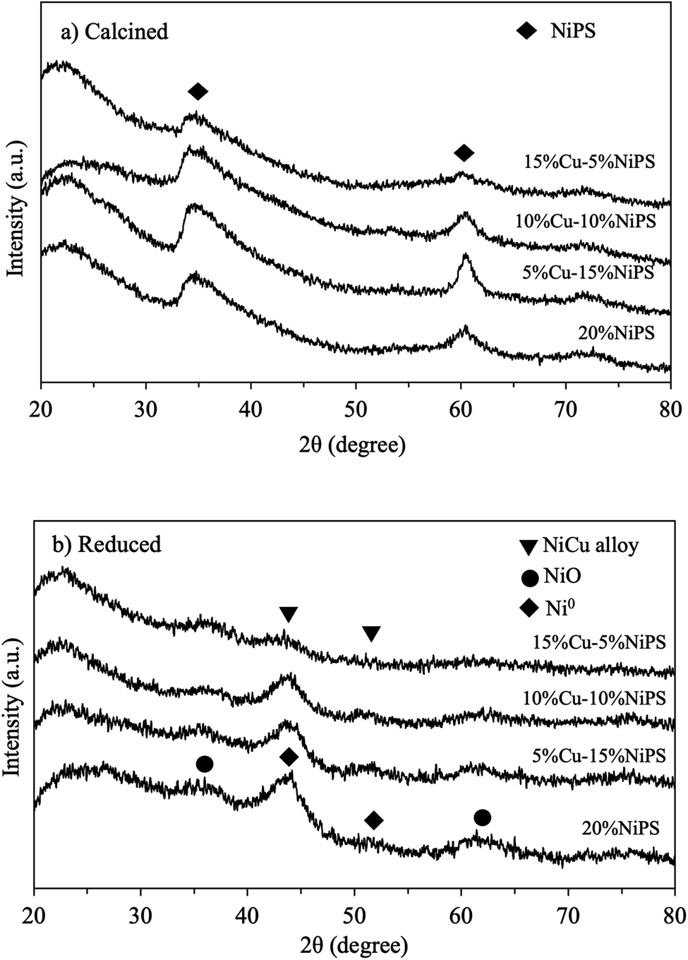 | ||
| Fig. 1 XRD patterns of monometallic 20% NiPS and bimetallic Cu–NiPS catalysts (a) calcined at 400 °C and (b) reduced at 600 °C. | ||
The morphology and metal dispersion of the calcined monometallic 20% NiPS and bimetallic Cu–NiPS catalysts were evaluated by SEM. Fig. 2 shows the SEM images of the (a) 20% NiPS, (b) 5% Cu–15% NiPS, (c) 10% Cu–10% NiPS, and (d) 15% Cu–5% NiPS catalysts along with EDX mappings. A similar dense solid morphology was clearly observed for all catalysts. In the EDX mappings, all samples showed uniform Ni and Cu dispersion corresponding to the amount of metal loading. The TEM analysis confirmed the layered structure of the phyllosilicate, metal dispersion and the average metal particle sizes (Fig. 3). For all calcined catalysts, the formation of a layered structure with randomly oriented fibers could be observed, while no metal particles were observed, indicating high dispersion of Ni2+ and Cu2+ in the phyllosilicate structure. On the other hand, the metal particles were clearly observed when the catalysts were reduced at 600 °C. This might be because the layer structure of phyllosilicate is decomposed, and the metals are exposed on the surface of the catalysts. The black spherical particles can be metallic Ni0 or Ni–Cu particles uniformly supported on silica. The average metal particle size was around 3.8–4.8 nm. The lattice patterns of both the monometallic 20% NiPS catalyst and bimetallic 15% Cu–5% NiPS catalyst were determined by high-resolution transmission electron microscopy (HR-TEM), and the results are illustrated in Fig. S2.† The lattice spacings (d-spacing) of both samples were measured at around 30 points in each sample. The d-spacing for Ni in the monometallic 20% NiPS catalyst was found to be 0.204 ± 0.004 nm, which aligns closely with the expected value (Ni-PDF: 00-004-0850). Furthermore, in the bimetallic 15% Cu–5% NiPS catalyst, the lattice spacing for the NiCu alloy was measured as 0.206 ± 0.007 nm. This value shows a slight shift from the expected d-spacings of pure Ni (PDF: 00-004-0850) and Cu (PDF: 00-004-0836). These results confirm the formation of a NiCu alloy in the bimetallic catalyst, highlighting the interactions between Ni and Cu at the atomic level.
 | ||
| Fig. 2 SEM images and EDX mappings of (a) 20% NiPS, (b) 5% Cu–15% NiPS, (c) 10% Cu–10% NiPS, and (d) 15% Cu–5% NiPS. | ||
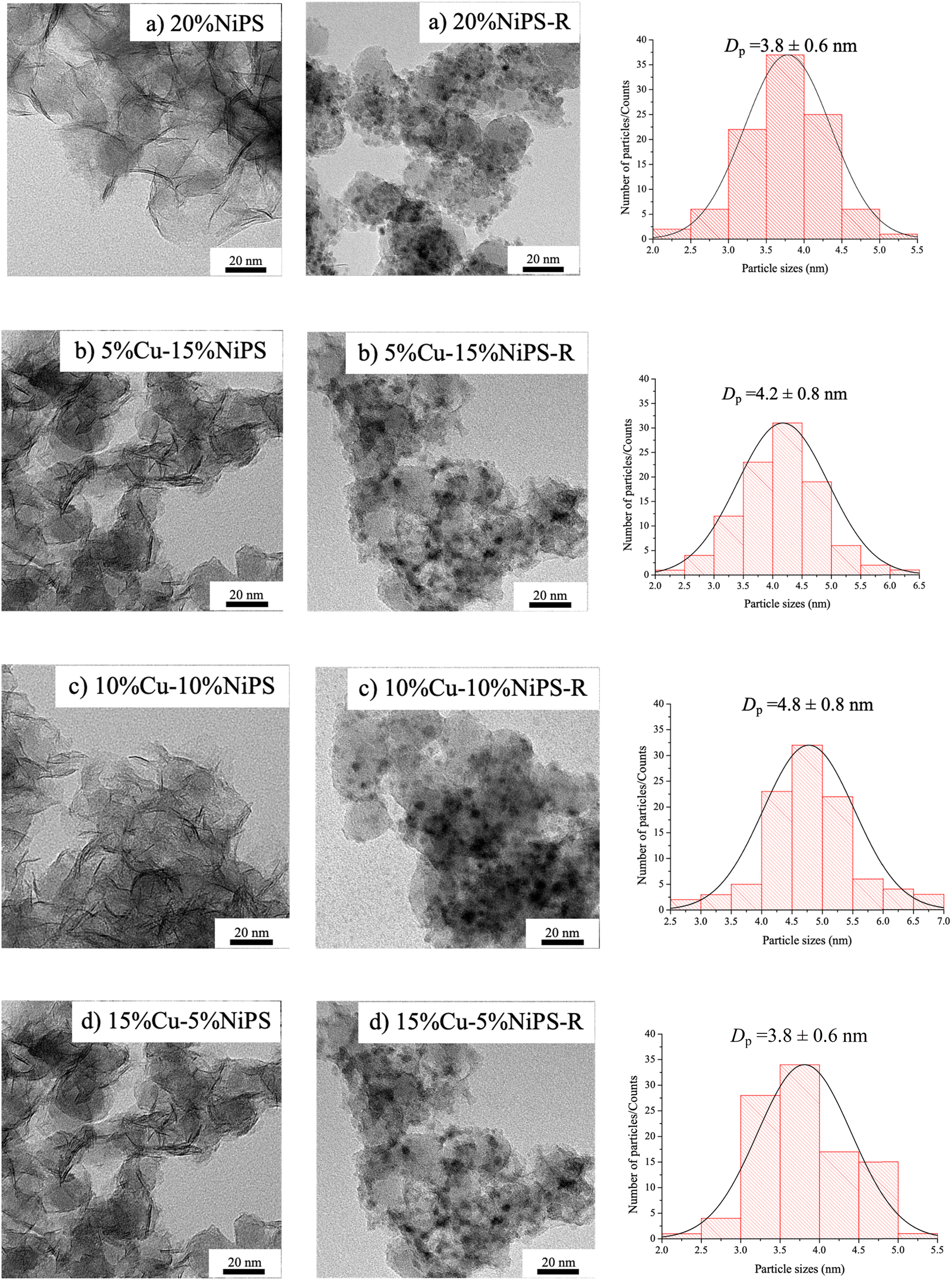 | ||
| Fig. 3 TEM images and metal particle size distributions of the calcined and reduced catalysts: (a) 20% NiPS, (b) 5% Cu–15% NiPS, (c) 10% Cu–10% NiPS, and (d) 15% Cu–5% NiPS. | ||
Table 1 summarizes the physicochemical properties of monometallic 20% NiPS and the bimetallic Cu–NiPS catalysts. The actual amount of total metal loaded on the catalysts determined by XRF was close to 20 wt% for every catalyst, which corresponds well with the intended metal loading. All the catalysts showed type IV N2 adsorption–desorption isotherms (Fig. S3†) with an H-type hysteresis loop, indicating that the Ni and Cu–Ni phyllosilicate structures were mesoporous. The BET surface area of the bimetallic Cu–NiPS catalysts increased significantly to ca. 320–380 m2 g−1 compared with the monometallic 20% NiPS (313 m2 g−1) catalyst, except for 10% Cu–10% NiPS (281 m2 g−1). However, 15% Cu–5% NiPS exhibited the highest BET surface area (378 m2 g−1) while 10% Cu–10% NiPS showed the lowest BET surface area. Moreover, the crystallite sizes of Ni and NiCu were determined by XRD using the Scherrer equation at 2θ = 43.7–43.8°, and the results coincided with those calculated based on TEM. The smallest NiCu crystallite size of around 4.0 nm was obtained for 15% Cu–5% NiPS, whereas the largest NiCu metal crystallite size of around 5.2 nm was obtained for 10% Cu–10% NiPS. This shows that the ratio of Ni and Cu influenced NiCu alloy formation. Particularly, in 10% Cu–10% NiPS, an equal amount of Ni and Cu loading tended to complete NiCu alloy formation, leading to the largest particle size.
| Catalysts | % Elemental compositionsa | N2 physisorptionb | Avg. crystallite size c (nm) | |||
|---|---|---|---|---|---|---|
| Ni | Cu | Total (Ni + Cu) | Average pore size diameter (nm) | SBET (m2 g−1) | ||
| a Determined by XRF.b Determined by N2 physical adsorption.c Determined from XRD data using the Scherrer equation at 2θ = 43.7–43.8°. | ||||||
| 20% NiPS | 19.1 | — | 19.1 | 12.7 | 313 | 4.3 |
| 5% Cu–15% NiPS | 14.3 | 4.6 | 18.9 | 11.8 | 319 | 4.4 |
| 10% Cu–10% NiPS | 9.8 | 9.7 | 19.5 | 13.8 | 281 | 5.2 |
| 15% Cu–5% NiPS | 5.0 | 13.3 | 18.3 | 13.6 | 378 | 4.0 |
The reduction behaviors of the monometallic 20% NiPS and bimetallic 5% Cu–15% NiPS, 10% Cu–10% NiPS, and 15% Cu–5% NiPS catalysts were investigated by the H2-TPR technique, and the results are illustrated in Fig. 4. 20% NiPS showed one reduction peak in the 300–700 °C range centered at around 600 °C, indicating the reduction of NiO species to metallic Ni0.30 The NiO species on general Ni/SiO2 catalysts are usually reduced at 400 °C, which is lower than the temperature required for 20% NiPS,31 indicating that the NiO species in the phyllosilicate structure has a strong metal–support interaction (SMSI). For the bimetallic Cu–NiPS catalysts, two reduction peaks were observed. The first reduction peak at around 190–205 °C was ascribed to the reduction of CuO to Cu+/Cu0 species, and the second one at around 617–650 °C was assigned to the reduction of NiO to metallic Ni0. However, the second reduction peaks of the bimetallic Cu–NiPS catalysts were at remarkably higher temperatures than that of monometallic 20% NiPS, suggesting strong synergetic interactions between Ni and Cu or the formation of the NiCu alloy.
 | ||
| Fig. 4 H2-TPR profiles of catalysts (a) 20% NiPS, (b) 5% Cu–15% NiPS, (c) 10% Cu–10% NiPS, and (d) 15% Cu–5% NiPS. | ||
The electronic states and surface compositions of monometallic 20% NiPS and the bimetallic Cu–NiPS catalysts were investigated by XPS analysis. The synergetic interactions between Ni and Cu in the bimetallic Cu–NiPS catalysts were also evaluated. Doublet peaks for Ni 2p and Cu 2p spectra in the calcined and reduced catalysts are demonstrated in Fig. 5. The binding energy (B.E.) of the Ni 2p peaks of the calcined catalysts were found at around 858.0–858.8 eV, which can be attributed to the Ni2+ species. These Ni 2p peaks shifted to the lower B.E. region at 855.1–856.4 eV after the reduction of catalysts at 600 °C, suggesting that Ni2+ was reduced to metallic Ni0. Particularly, the Ni 2p peak of the bimetallic Cu–NiPS catalysts shifted remarkably to lower B.E. values than that of monometallic 20% NiPS. This can be ascribed to electron transfer from Cu to Ni due to the formation of the Ni–Cu alloy.32,33 The B.E. of the Cu 2p peak of calcined Cu–NiPS was found at around 935.4–936 eV and could be assigned to the Cu2+ species. The Cu 2p peaks after reduction shifted to lower B.E. values at 932.7–933.4 eV, corresponding to the Cu+/Cu0 species. Moreover, these Cu 2p peaks of bimetallic Cu–NiPS catalysts significantly shifted to higher B.E. than that of monometallic 20% CuPS (not used in this study), and the results are shown in Fig. S4.† From these findings, it can be confirmed that electron transfer occurs from Cu to Ni to form the Ni–Cu alloy. The deconvoluted peaks of the copper species can be assigned to metallic Cu0 (B.E. 932.7–932.9 eV), Cu+ (B.E. 934.4–934.9 eV), and Cu2+ (B.E. 936.4–936.9 eV). The percentages of metallic Cu0 and Cu+ species (as illustrated in Fig. 5d) gradually increased when the amount of Cu loading was increased from 5 to 15%. Although Cu2+ species always appear on the surface of reduced Cu–NiPS catalysts, they were not considered in this work because the Cu–NiPS catalysts were subjected to ex situ reduction before the XPS analysis. The remaining Cu2+ species were formed from the partial oxidation of Cu0/Cu+ on the catalysts after reduction.
 | ||
| Fig. 5 XPS spectra: (a) Ni 2p and (b) Cu 2p of the calcined catalysts; (c) Ni 2p and (d) Cu 2p of the reduced catalysts. | ||
The surface composition data obtained after the reduction of the monometallic 20% NiPS and bimetallic Cu–NiPS catalysts are summarized in Table 2. The total atomic concentration ratio of the Ni and Cu species on silica the surface (Ni + Cu)/Si was not significantly different among the Cu–NiPS catalysts (around 0.23–0.27%). However, Cu showed higher dispersion on the catalyst surface than Ni considering the Cu/Si and Ni/Si ratios at the same metal loading. Furthermore, the Cu/Ni ratios represented two different Ni–Cu alloy types: (i) a nickel-rich Ni–Cu alloy appeared on 5% Cu–15% NiPS and (ii) a copper-rich Ni–Cu alloy appeared on the 10% Cu–10% NiPS and 15% Cu–5% NiPS catalysts. The exact amounts of Cu0 and Cu+ on the catalyst surfaces were calculated in terms of atomic concentration ratios of Cu0/Si and Cu+/Si. 15% Cu–5% NiPS had the highest atomic concentration ratios of Cu0/Si (0.14) and Cu+/Si (0.04), whereas 5% Cu–15% NiPS had the lowest atomic concentration ratios of Cu0/Si (0.05) and Cu+/Si (0.02) on the surface.
| Catalysts | Binding energy (eV) | Atomic concentration ratio | |||||||
|---|---|---|---|---|---|---|---|---|---|
| Ni 2p | Cu 2p | Si 1s | Ni/Si | Cu/Si | (Ni + Cu)/Si | Cu/Ni | Cu0/Si | Cu+/Si | |
| 20% NiPS | 856.4 | — | 106.3 | 0.20 | — | — | — | — | — |
| 5% Cu–15% NiPS | 856.1 | 933.4 | 106.0 | 0.14 | 0.09 | 0.23 | 0.64 | 0.05 | 0.02 |
| 10% Cu–10% NiPS | 855.8 | 933.2 | 106.9 | 0.11 | 0.16 | 0.27 | 1.45 | 0.10 | 0.03 |
| 15% Cu–5% NiPS | 855.1 | 932.7 | 105.3 | 0.02 | 0.21 | 0.23 | 10.50 | 0.14 | 0.04 |
3.2 Catalytic performance of the monometallic 20% NiPS and bimetallic Cu–NiPS catalysts in the liquid-phase selective hydrogenation of FF to FA
The catalytic performance of the monometallic 20% NiPS and bimetallic Cu–NiPS catalysts in the liquid-phase selective hydrogenation of FF to FA was evaluated in a batch-type stainless steel reactor under mild reaction conditions (H2 pressure = 20 bar, 100 °C with n-propanol as the solvent). The results are shown in Table 3. To make the activity difference clear, the conversion of FF was kept low. For a reaction time of 30 min, 20% NiPS gave the highest conversion of FF at around 41%, while bimetallic Cu–NiPS gave lower FF conversion rates (22–33%). The TOFs of the catalysts calculated from moles of FF converted to moles of metal were in the range of 0.34–0.60 h−1. The highest TOF was obtained on monometallic 20% NiPS. Similar results have been reported for FeNi/SiO2 and Ni/SiO2.34 FA selectivity was the lowest on monometallic 20% NiPS. Among the Cu–NiPS catalysts, the highest FF conversion (33%) and highest selectivity to FA (94%) were achieved on the 15% Cu–5% NiPS catalyst. Thus, the combination of Cu reduced the hydrogenation activity but increased the selectivity to FA by suppressing consecutive hydrogenation of FA. Increasing Cu loading on the bimetallic Cu–NiPS catalysts improves the selectivity to FA because surface enrichment of Cu and electron transfer from Cu to Ni contribute to the stabilization of the adsorbed C![[double bond, length as m-dash]](https://www.rsc.org/images/entities/char_e001.gif) O group of FF. Moreover, the metallic Cu0 species on bimetallic Cu–NiPS facilitate H2 dissociation, while the Cu+ species can stabilize the carbon atom of the carbonyl group (CO).35 Thus, hydrogen is easily transferred to hydrogenate CO in FF to FA, and then FA is immediately desorbed from the surface of the catalysts by the synergetic interaction between Ni and the Cu0/Cu+ species.
O group of FF. Moreover, the metallic Cu0 species on bimetallic Cu–NiPS facilitate H2 dissociation, while the Cu+ species can stabilize the carbon atom of the carbonyl group (CO).35 Thus, hydrogen is easily transferred to hydrogenate CO in FF to FA, and then FA is immediately desorbed from the surface of the catalysts by the synergetic interaction between Ni and the Cu0/Cu+ species.
| Catalyst | Conversion (%) | Selectivity (%) | TOF (h−1) | ||
|---|---|---|---|---|---|
| FA | THFAb | FEc | |||
| a Reaction conditions: catalyst 25 mg, furfural 2.4 mmol, n-propanol 10 mL, H2 pressure 20 bar, reaction temperature 100 °C and reaction time 30 min.b THFA: tetrahydrofurfuryl alcohol.c FE: furfuryl propyl ether. | |||||
| 20% NiPS | 41 | 61 | 37 | 2 | 0.60 |
| 5% Cu–15% NiPS | 22 | 76 | 24 | 0.0 | 0.34 |
| 10% Cu–10% NiPS | 27 | 93 | 7 | 0.0 | 0.40 |
| 15% Cu–5% NiPS | 33 | 94 | 6 | 0.0 | 0.53 |
To clarify the catalytic performance of the monometallic 20% NiPS and bimetallic Cu–NiPS catalysts in the liquid-phase selective hydrogenation of FF to FA, their time on stream (15–240 min.) behavior was studied (Fig. 6). For monometallic 20% NiPS, FF conversion increased from 27% to 98% and the selectivity to FA remarkably decreased from 71% to 23%, when the reaction time was prolonged from 15 to 240 min. For bimetallic Cu–NiPS, FF conversion significantly increased when the Cu loading was increased from 5% to 15%, but their FF conversion efficiency was lower than that of monometallic 20% NiPS. However, the FA selectivity of bimetallic Cu–NiPS was higher than that of monometallic 20% NiPS, especially for 15% Cu–5% NiPS (90% @ 240 min). Generally, Ni catalysts exhibit good activity in the hydrogenation of CC of aromatic rings or/and CO of aldehyde groups since the Ni surface prefers η2 (CC, CO) adsorption to form a hydroxyalkyl intermediate, resulting in high FF conversion. However, the selectivity to FA decreased due to the over-hydrogenation of FF to THFA on 20% NiPS.14,36,37 The selectivity to THFA of all catalysts are given in Fig. S5.†
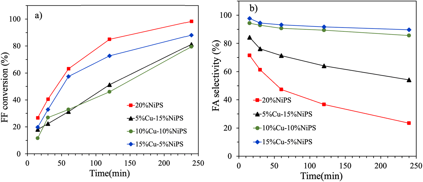 | ||
| Fig. 6 The catalytic conversion of FF (a) and the selectivity to FA (b) in the liquid-phase selective hydrogenation of FF to FA on the monometallic 20% NiPS and bimetallic Cu–NiPS catalysts. | ||
Fig. 7 shows the catalytic performance of the monometallic 20% NiPS and bimetallic Cu–NiPS catalysts in the liquid-phase selective hydrogenation of FF to FA. In the case of monometallic 20% NiPS, FA selectivity decreased while the FF conversion increased. Among the Cu–NiPS catalysts, the highest catalytic performance was achieved on the 15% Cu–5% NiPS catalyst. The FA selectivity of 15% Cu–5% NiPS and 10% Cu–10% NiPS catalysts were almost constant at around 90%. The over-hydrogenation of FA to THFA was suppressed by the presence of more Cu0/Cu+ on the NiCu alloy particles.17 Due to the synergetic interaction between Ni and Cu, Ni–Cu alloy formation (evidenced by XRD and XPS) and the Cu+ species changed the adsorption behavior on the catalyst surface.38 The copper-rich Ni–Cu alloy catalysts (15% Cu–5% NiPS and 10% Cu–10% NiPS) showed excellent FA selectivity since they had more metallic Cu0 species that could absorb carbonyl groups by the η1 (CO) mechanism. At the same time, the Cu+ species could stabilize the carbon in the carbonyl group. Moreover, electron transfer from Cu to Ni led to the formation of a copper-rich NiCu alloy, thus reducing the adsorption strength of FF and FA on metallic Ni0. Therefore, the hydrogenation of CO was favored over the hydrogenation of CC in the furan ring. At the same FF conversion rate, the preference for CO due to the effect of Cu was evident. Therefore, 15% Cu–5% NiPS illustrated the best catalytic performance in the liquid-phase selective hydrogenation of FF to FA. The formation of the smallest copper-rich NiCu alloy particles on 15% Cu–5% NiPS also contributed to their high dispersion, forming a copper-rich surface structure that yielded better catalytic performance.
 | ||
| Fig. 7 Catalytic performance of the monometallic 20% NiPS and bimetallic Cu–NiPS catalysts toward the liquid-phase selective hydrogenation of FF to FA. | ||
Scheme 1 shows the possible pathways for the hydrogenation of furfural to furfuryl alcohol on the monometallic 20% NiPS and 15% Cu–5% NiPS catalysts. On monometallic 20% NiPS, H2 is dissociated from the metallic Ni0 surface, and the FF molecules are then strongly adsorbed in the η2 (CC, CO) configuration39 The hydride species (H−) can attach to the carbon of the carbonyl group (CO), as well as the carbon in the furan ring (CC), and hydrogenation occurs on both sites to form FA and THFA, respectively.40–42 On 15% Cu–5% NiPS, which consists of small particle sites due to the highly dispersed copper-rich NiCu alloys, the co-existence of Cu0/Cu+ in the NiCu alloy is responsible for the superior catalytic conversion of FF to FA. Metallic Cu0 and Ni0 facilitate the dissociation of H2. At the same time, the Cu0/Cu+ species stabilize the carbonyl group, promoting hydrogen spillover to form FA. Furthermore, the electrons transferred from Cu to Ni cause weak adsorption of FF/FA on the metallic Ni0 sites compared with those on the monometallic 20% NiPS catalyst. Thus, the over-hydrogenation of FF to THFA is suppressed. Therefore, the 15% Cu–5% NiPS catalyst gives the best catalytic performance in the liquid-phase selective hydrogenation of FF to FA.
 | ||
| Scheme 1 Possible pathways for the hydrogenation of furfural to furfuryl alcohol on the monometallic 20% NiPS and 15% Cu–5% NiPS catalysts. | ||
Table 4 shows the catalytic performance of some reported NiCu catalysts in the liquid-phase selective hydrogenation of FF to FA compared with the 15% Cu–5% NiPS catalyst synthesized in this work. According to the literature, the composition of the NiCu alloy on the support affects the catalytic activity and selectivity. Moreover, most of the NiCu catalysts [entries 1–5] need high H2 pressure (H2 = 3–5 MPa) and high reaction temperatures (120–190 °C). In comparison, the 15% Cu–5% NiPS catalyst developed in this work gives the best catalytic activity at mild reaction conditions (100 °C, H2 = 2 MPa), similar to 2% Ni–5% Cu/SiO2.
| Entry | Catalyst | Temp. (°C) | Pressure (MPa) | Time (min) | Conv. (%) | FA sel. (%) | Ref. |
|---|---|---|---|---|---|---|---|
| 1 | Ni–Cu sol–gel | 130 | 5 | — | 70 | 100 | 43 |
| 2 | Cu3Ni1/MgAlO | 150 | 3 | 180 | 100 | 55 | 44 |
| 3 | Cu1Ni3/MgAlO | 150 | 3 | 180 | 100 | 69 | 44 |
| 4 | Ni1Cu1Al1 | 190 | 5 | 240 | 100 | 61 | 45 |
| 5 | CuNiOx | 120 | 3 | 45 | 20 | 98 | 35 |
| 6 | 2% Ni–5% Cu/SiO2 | 100 | 2 | 120 | 94 | 64 | 46 |
| 7 | 15% Cu–5% NiPS | 100 | 2 | 240 | 88 | 90 | This work |
The reusability of the 15% Cu–5% NiPS catalyst was investigated, and the results are shown in Fig. 8 After each reaction, the spent catalyst was separated and washed with n-propanol to remove residual compounds on the catalyst. Over three consecutive cycles, the FF conversion efficiency of the catalyst slightly decreased from 73% to 64%, while the FA selectivity remained at over 90%. To investigate the decline in FF conversion after four cycles, the spent catalyst was analyzed using X-ray photoelectron spectroscopy (XPS) to assess its surface composition and metal species. Additionally, inductively coupled plasma (ICP) analysis was performed to investigate metal leaching into the liquid products. Fig. S6† displays the Ni 2p, Cu 2p, and C 1s XPS spectra of the spent 15% Cu–5% NiPS catalyst in comparison with the fresh catalyst. The Ni 2p spectra of the spent catalyst exhibited a peak shift to a higher B.E. of 856.7 eV, indicating the transformation of metallic Ni0 to Ni2+. Similarly, the Cu 2p spectra showed a shift to a higher B.E. of 933.8 eV, which reflects the conversion of metallic Cu0 to Cu+/Cu2+. Furthermore, the C 1s peaks found at B.E. 285.4, 287.4, and 289.2 eV could be assigned to different types of carbon, namely C–C, CO, and O–CO, respectively. Table S1† presents the surface concentrations of elements in both the spent and fresh 15% Cu–5% NiPS catalysts. To evaluate the carbon content in the spent catalysts, Ag tape was used to prepare the XPS samples, and the Ag 3d peak at B.E. 368.2 eV was used as the reference. The results indicated that the atomic concentration of (Ni + Cu)/Si in the spent catalyst decreased by approximately 12.5%, from 0.24 to 0.21, compared with the fresh catalyst. This suggests that Ni and/or Cu may be leaching or their surfaces could be obscured by other substances. Notably, carbon was detected on the surface of the spent catalyst (C/Si = 0.53), while it was absent in the fresh catalyst. This carbon likely originates from the strong adsorption of the substrate (FF/FA), leading to the blockage of the active sites and a reduction in catalytic performance. Furthermore, the liquid products after four cycles were analyzed via ICP to assess Ni and Cu leaching; the analysis revealed that 0.4 wt% of Ni and 0.2 wt% of Cu had leached into the liquid phase. Consequently, the decrease in FF conversion from 73% to 64% after four successive cycles can be attributed to both leaching of Ni and Cu and the deposition of carbon on the catalyst surface. However, 15% Cu–5% NiPS has very good stability due to the synergetic effect between Ni and Cu in the bimetallic alloy and the strong metal–support interaction between the highly dispersed NiCu alloy particles and SiO2.
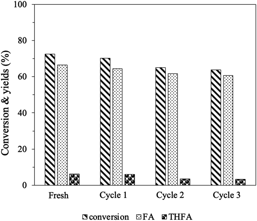 | ||
| Fig. 8 Reusability test of the 15% Cu–5% NiPS catalyst used for the hydrogenation of FF to FA. | ||
4. Conclusions
Monometallic 20% NiPS and bimetallic Cu–NiPS catalysts with various Ni/Cu ratios were synthesized by the ammonia evaporation hydrothermal method and tested in the liquid phase selective hydrogenation of FF to FA. Compared with monometallic 20% NiPS, all bimetallic Cu–NiPS catalysts demonstrated improved catalytic performance. The 15% Cu–5% NiPS catalyst exhibited the best catalytic performance. Surface enrichment of Cu was observed to influence the electronic nature of the NiCu alloy in 15% Cu–5% NiPS, which further improved the adsorption of FF, dissociation of H2, and desorption of FA, resulting in higher FF conversion and higher FA selectivity.Data availability
The data supporting this article are provided as part of the ESI.†Conflicts of interest
There are no conflicts to declare.Acknowledgements
This work was supported by Office of the Permanent Secretary, Ministry of Higher Education, Science, Research and Innovation (OPS MHESI), Thailand Science Research and Innovation (TSRI) and King Mongkut’s Institute of Technology Ladkrabang, Thailand (Grant No. RGNS 64 – 246). The Research Team Promotion grant for J. P. from the National Research Council of Thailand (NRCT), and School of Science, King Mongkut’s Institute of Technology Ladkrabang is gratefully acknowledged.References
- R. Mariscal, P. Maireles-Torres, M. Ojeda, I. Sádaba and M. López Granados, Furfural: a renewable and versatile platform molecule for the synthesis of chemicals and fuels, Energy Environ. Sci., 2016, 9, 1144–1189, 10.1039/C5EE02666K.
- Y. Luo, Z. Li, X. Li, X. Liu, J. Fan, J. H. Clark and C. Hu, The production of furfural directly from hemicellulose in lignocellulosic biomass: a review, Catal. Today, 2019, 319, 14–24, DOI:10.1016/j.cattod.2018.06.042.
- L. Zhang, G. Xi, K. Yu, H. Yu and X. Wang, Furfural production from biomass–derived carbohydrates and lignocellulosic residues via heterogeneous acid catalysts, Ind. Crops Prod., 2017, 98, 68–75, DOI:10.1016/j.indcrop.2017.01.014.
- X. Li, P. Jia and T. Wang, Furfural: A Promising Platform Compound for Sustainable Production of C4 and C5 Chemicals, ACS Catal., 2016, 6, 7621–7640, DOI:10.1021/acscatal.6b01838.
- W. Zhang, Y. Zhu, S. Niu and Y. Li, A study of furfural decarbonylation on K-doped Pd/Al2O3 catalysts, J. Mol. Catal. A:Chem., 2011, 335, 71–81, DOI:10.1016/j.molcata.2010.11.016.
- J. Long, W. Zhao, H. Li and S. Yang, Furfural as a renewable chemical platform for furfuryl alcohol production, in Biomass, Biofuels, Biochemicals, Elsevier, 2020, pp. 299–322, DOI:10.1016/B978-0-444-64307-0.00011-1.
- T. A. Natsir and S. Shimazu, Fuels and fuel additives from furfural derivatives via etherification and formation of methylfurans, Fuel Process. Technol., 2020, 200, 106308, DOI:10.1016/j.fuproc.2019.106308.
- R. Rao, A. Dandekar, R. T. K. Baker and M. A. Vannice, Properties of Copper Chromite Catalysts in Hydrogenation Reactions, J. Catal., 1997, 171, 406–419, DOI:10.1006/jcat.1997.1832.
- D. Liu, D. Zemlyanov, T. Wu, R. J. Lobo-Lapidus, J. A. Dumesic, J. T. Miller and C. L. Marshall, Deactivation mechanistic studies of copper chromite catalyst for selective hydrogenation of 2-furfuraldehyde, J. Catal., 2013, 299, 336–345, DOI:10.1016/j.jcat.2012.10.026.
- H. Li, H. Luo, L. Zhuang, W. Dai and M. Qiao, Liquid phase hydrogenation of furfural to furfuryl alcohol over the Fe-promoted Ni-B amorphous alloy catalysts, J. Mol. Catal. A:Chem., 2003, 203, 267–275, DOI:10.1016/S1381-1169(03)00368-6.
- P. Weerachawanasak, P. Krawmanee, W. Inkamhaeng, F. J. Cadete Santos Aires, T. Sooknoi and J. Panpranot, Development of bimetallic Ni-Cu/SiO2 catalysts for liquid phase selective hydrogenation of furfural to furfuryl alcohol, Catal. Commun., 2021, 149, 106221, DOI:10.1016/j.catcom.2020.106221.
- Z. Wang, X. Wang, C. Zhang, M. Arai, L. Zhou and F. Zhao, Selective hydrogenation of furfural to furfuryl alcohol over Pd/TiH2 catalyst, Mol. Catal., 2021, 508, 111599, DOI:10.1016/j.mcat.2021.111599.
- M. M. Villaverde, N. M. Bertero, T. F. Garetto and A. J. Marchi, Selective liquid-phase hydrogenation of furfural to furfuryl alcohol over Cu-based catalysts, Catal. Today, 2013, 213, 87–92, DOI:10.1016/j.cattod.2013.02.031.
- R. Šivec, M. Huš, B. Likozar and M. Grilc, Furfural hydrogenation over Cu, Ni, Pd, Pt, Re, Rh and Ru catalysts: ab initio modelling of adsorption, desorption and reaction micro-kinetics, Chem. Eng. J., 2022, 436, 135070, DOI:10.1016/j.cej.2022.135070.
- T. Intana, S. Thongratkaew, J. Nonkumwong, W. Donphai, T. Witoon, M. Chareonpanich, N. Sano, K. Faungnawakit and S. Kiatphuengpore, Kinetics study of the selective hydrogenation of furfural to furfuryl alcohol over CuAl2O4 spinel catalyst, Mol. Catal., 2023, 547, 113294, DOI:10.1016/j.mcat.2023.113294.
- X. Tian, Y. Dong and M. Zahid, Synergetic catalysis of Pt/WN-TiO2 nanocomposites for selective hydrogenation of furfural to valuable furfuryl alcohol, Mol. Catal., 2023, 545, 113188, DOI:10.1016/j.mcat.2023.113188.
- S. Sitthisa, T. Sooknoi, Y. Ma, P. B. Balbuena and D. E. Resasco, Kinetics and mechanism of hydrogenation of furfural on Cu/SiO2 catalysts, J. Catal., 2011, 277, 1–13, DOI:10.1016/j.jcat.2010.10.005.
- P. A. Kamble, C. P. Vinod, V. K. Rathod and M. L. Kantam, Hydrogenation of furfural to tetrahydrofurfuryl alcohol over nickel-supported on organoclay catalyst, Appl. Catal., A, 2024, 674, 119621, DOI:10.1016/j.apcata.2024.119621.
- Z. Li, H. Yang, S. Feng, Q. Sun, G. Gao, Z. Jiang and C. Hu, Selective hydrogenation of furfural to tetrahydrofurfuryl alcohol in isopropanol over hydrotalcite-derived nickel-based catalyst, Chem. Eng. J., 2024, 482, 149044, DOI:10.1016/j.cej.2024.149044.
- F. Dong, Y. Zhu, H. Zhao and Z. Tang, Ratio-controlled synthesis of phyllosilicate-like materials as precursors for highly efficient catalysis of the formyl group, Catal. Sci. Technol., 2017, 7, 1880–1891, 10.1039/C7CY00233E.
- W. Prasanseang, K. Choojun, Y. Poo-arporn, A. L. Huang, Y. C. Lin and T. Sooknoi, Linear long-chain α-olefins from hydrodeoxygenation of methyl palmitate over copper phyllosilicate catalysts, Appl. Catal., A, 2022, 635, 118555, DOI:10.1016/j.apcata.2022.118555.
- H. Du, X. Ma, M. Jiang, P. Yan, Y. Zhao and Z. Conrad Zhang, Efficient Ni/SiO2 catalyst derived from nickel phyllosilicate for xylose hydrogenation to xylitol, Catal. Today, 2021, 365, 265–273, DOI:10.1016/j.cattod.2020.04.009.
- L. Huang, L. Lin, C. C. Chen, R. Ye, L. B. Zhu, J. X. Yang, Y. Y. Qin, J. K. Vheng and Y. G. Yao, β-Cyclodextrin promoted the formation of copper phyllosilicate on Cu-SiO2 microspheres catalysts to enhance the low-temperature hydrogenation of dimethyl oxalate, J. Catal., 2022, 413, 943–955, DOI:10.1016/j.jcat.2022.07.016.
- Z. Q. Wang, Z. N. Xu, S. Y. Peng, M. J. Zhang, G. Lu, Q. S. Chen, Y. Chen and G. C. Guo, High-Performance and Long-Lived Cu/SiO2 Nanocatalyst for CO2 Hydrogenation, ACS Catal., 2015, 5, 4255–4259, DOI:10.1021/acscatal.5b00682.
- S. Liu, X. Cha, X. Wang, K. Xu, K. B. Tan, D. Cai, J. Huang, Q. Li and G. Zhan, Atomic layer deposition of alumina on hollow nickel phyllosilicate nanosheets for enhanced CO2 thermal hydrogenation performance, Chem. Eng. Sci., 2024, 283, 119394, DOI:10.1016/j.ces.2023.119394.
- Q. Zhang, M. Wang, T. Zhang, Y. Wang, X. Tang and P. Ning, A stable Ni/SBA-15 catalyst prepared by the ammonia evaporation method for dry reforming of methane, RSC Adv., 2015, 5, 94016–94024, 10.1039/C5RA18845H.
- S. Kuhaudomlap, O. Mekasuwandumrong, P. Praserthdam, K. M. Lee, C. W. Jones and J. Panpranot, Influence of Highly Stable Ni2+ Species in Ni Phyllosilicate Catalysts on Selective Hydrogenation of Furfural to Furfuryl Alcohol, ACS Omega, 2023, 8, 249–261, DOI:10.1021/acsomega.2c03590.
- J. Ashok, Y. Kathiraser, M. L. Ang and S. Kawi, Ni and/or Ni–Cu alloys supported over SiO2 catalysts synthesized via phyllosilicate structures for steam reforming of biomass tar reaction, Catal. Sci. Technol., 2015, 5, 4398–4409, 10.1039/C5CY00650C.
- E. T. Saw, U. Oemar, X. R. Tan, Y. Du, A. Borgna, K. Hidajat and S. Kawi, Bimetallic Ni–Cu catalyst supported on CeO2 for high-temperature water–gas shift reaction: methane suppression via enhanced CO adsorption, J. Catal., 2014, 314, 32–46, DOI:10.1016/j.jcat.2014.03.015.
- T. Lehmann, T. Wolff, C. Hamel, P. Veit, B. Garke and A. Seidel-Morgenstern, Physico-chemical characterization of Ni/MCM-41 synthesized by a template ion exchange approach, Microporous Mesoporous Mater., 2012, 151, 113–125, DOI:10.1016/j.micromeso.2011.11.006.
- R. P. Ye, W. Gong, Z. Sun, Q. Sheng, X. Shi, T. Wang, Y. Yao, J. J. Razink and L. Z. Z. Lin, et.al., Enhanced stability of Ni/SiO2 catalyst for CO2 methanation: derived from nickel phyllosilicate with strong metal-support interactions, Energy, 2019, 188, 116059, DOI:10.1016/j.energy.2019.116059.
- Y. Wu, W. Gui, X. Liu, L. Zhang, S. Wang, Z. Wang and C. Zhang, Promotional Effect of Cu for Catalytic Amination of Diethylene Glycol with Tertiarybutylamine over Ni–Cu/Al2O3 Catalysts, Catal. Lett., 2020, 150, 2427–2436, DOI:10.1007/s10562-020-03145-8.
- A. R. Naghash, T. H. Etsell and S. Xu, XRD and XPS Study of Cu–Ni Interactions on Reduced Copper–Nickel–Aluminum Oxide Solid Solution Catalysts, Chem. Mater., 2006, 18, 2480–2488, DOI:10.1021/cm051910o.
- D. Shi, Q. Yang, C. Peterson, A. F. Lamic-Humblot, J. S. Girardon, A. Griboval-Constant, L. Stievano, M. T. Sougrati, V. Briois, P. A. J. Bagot and R. Wojcieszak, et al., Bimetallic Fe-Ni/SiO2 catalysts for furfural hydrogenation: identification of the interplay between Fe and Ni during deposition-precipitation and thermal treatments, Catal. Today, 2019, 334, 162–172, DOI:10.1016/j.cattod.2018.11.041.
- W. Fang, S. Liu, A. K. Steffensen, L. Schill, G. Kastlunger and A. Riisager, On the Role of Cu+ and CuNi Alloy Phases in Mesoporous CuNi Catalyst for Furfural Hydrogenation, ACS Catal., 2023, 13, 8437–8444, DOI:10.1021/acscatal.3c01767.
- Y. Nakagawa, H. Nakazawa, H. Watanabe and K. Tomishige, Total Hydrogenation of Furfural over a Silica-Supported Nickel Catalyst Prepared by the Reduction of a Nickel Nitrate Precursor, ChemCatChem, 2012, 4, 1791–1797, DOI:10.1002/cctc.201200218.
- B. Chen, F. Li, Z. Huang and G. Yuan, Tuning catalytic selectivity of liquid-phase hydrogenation of furfural via synergistic effects of supported bimetallic catalysts, Appl. Catal., A, 2015, 500, 23–29, DOI:10.1016/j.apcata.2015.05.006.
- F. Tang, L. Wang, M. Dessie Walle, A. Mustapha and Y. N. Liu, An alloy chemistry strategy to tailoring the d-band center of Ni by Cu for efficient and selective catalytic hydrogenation of furfural, J. Catal., 2020, 383, 172–180, DOI:10.1016/j.jcat.2020.01.019.
- K. Christmann, R. J. Behm, G. Ertl, M. A. Van Hove and W. H. Weinberg, Chemisorption geometry of hydrogen on Ni(111): order and disorder, J. Chem. Phys., 1979, 70, 4168–4184, DOI:10.1063/1.438041.
- S. Liu, N. Govindarajan and K. Chan, Understanding Activity Trends in Furfural Hydrogenation on Transition Metal Surfaces, ACS Catal., 2022, 12, 12902–12910, DOI:10.1021/acscatal.2c03822.
- V. Vorotnikov, G. Mpourmpakis and D. G. Vlachos, DFT Study of Furfural Conversion to Furan, Furfuryl Alcohol, and 2-Methylfuran on Pd(111), ACS Catal., 2012, 2, 2496–2504, DOI:10.1021/cs300395a.
- N. Shan, M. K. Hanchett and B. Liu, Mechanistic Insights Evaluating Ag, Pb, and Ni as Electrocatalysts for Furfural Reduction from First-Principles Methods, J. Phys. Chem. C, 2017, 121, 25768–25777, DOI:10.1021/acs.jpcc.7b06778.
- S. A. Khromova, M. V. Bykova, O. A. Bulavchenko, D. Yu Ermakov, A. A. Saraev, V. V. Kaichev, R. H. Venderbosch and V. A. Yakovlev, Furfural Hydrogenation to Furfuryl Alcohol over Bimetallic Ni–Cu Sol–Gel Catalyst: A Model Reaction for Conversion of Oxygenates in Pyrolysis Liquids, Top. Catal., 2016, 59, 1413–1423, DOI:10.1007/s11244-016-0649-0.
- X. Chen, W. Liu, J. Luo, H. Niu, R. Li and C. Liang, Structure Evolution of Ni–Cu Bimetallic Catalysts Derived from Layered Double Hydroxides for Selective Hydrogenation of Furfural to Tetrahydrofurfuryl Alcohol, Ind. Eng. Chem. Res., 2022, 61, 12953–12965, DOI:10.1021/acs.iecr.2c01624.
- A. Aldureid, F. Medina, G. S. Patience and D. Montané, Ni-Cu/Al2O3 from Layered Double Hydroxides Hydrogenates Furfural to Alcohols, Catalysts, 2022, 12, 390, DOI:10.3390/catal12040390.
- P. Weerachawanasak, P. Krawmanee, W. Inkamhaeng, F. J. Cadete Santos Aires, T. Sooknoi and J. Panpranot, Development of bimetallic Ni-Cu/SiO2 catalysts for liquid phase selective hydrogenation of furfural to furfuryl alcohol, Catal. Commun., 2021, 149, 106221, DOI:10.1016/j.catcom.2020.106221.
Footnote |
| † Electronic supplementary information (ESI) available. See DOI: https://doi.org/10.1039/d4ra07162j |
| This journal is © The Royal Society of Chemistry 2024 |