
 Open Access Article
 This Open Access Article is licensed under a Creative Commons Attribution-Non Commercial 3.0 Unported Licence
A study on the efficient separation of oily water using mullite whiskers membrane through combined filtration and electrofiltration†
Masoumeh Naseri a,
Mohammadreza Omidkhah*a and
Seyed Foad Mousavib
a,
Mohammadreza Omidkhah*a and
Seyed Foad Mousavib
aProcess Engineering Department, Faculty of Chemical Engineering, Tarbiat Modares University, Tehran, Iran. E-mail: omidkhah@modares.ac.ir; Tel: +98-21-82-88-3334
bSchool of Chemical, Petroleum and Gas Engineering, Iran University of Science and Technology, Tehran, Iran
First published on 24th September 2024
Abstract
This study explores the efficacy of a ceramic membrane combining filtration, electrofiltration, and backwashing for oily water treatment. A secondary mullite membrane was synthesized, showcasing high permeate flux (534 LMH), biaxial flexural strength (75.21 MPa), and cost-effectiveness. Operational parameters, set at 2 bar pressure and 0.727 m s−1 cross-flow velocity, were optimized for desirable permeate flux and oil removal rates. Critical electric field intensity (Ecrit) ranged from 50 to 55 V, guiding optimal voltage selection for electrofiltration. Electrokinetic phenomena, such as electrophoresis and electroosmosis, addressed fouling issues. Higher salt concentrations exacerbated fouling and reduced electric field efficiency. Energy analysis revealed potential savings, dropping from 3.88 kW h m3 without voltage to 2.71 kW h m3 at 65 V for salt-free solutions. However, higher salt concentrations increased fouling, elevating energy consumption. These findings affirm the value of affordable ceramic membranes for oily water treatment, stressing the need for parameter optimization to enhance performance and energy efficiency.
1. Introduction
Oily wastewater from industries such as oil refineries, petrochemical plants, and offshore drilling operations poses significant environmental challenges, degrading water quality and threatening biodiversity and human health.1,2 With oil concentrations in wastewater ranging from 10 mg L−1 to 1000 mg L−1,3 the need for effective treatment and management has become increasingly critical.4–6 Traditional methods like physical, chemical, and biological processes struggle with limitations such as high costs, complex operations, and secondary pollutants.7–10 In contrast, membrane-based separation techniques have gained attention for their high efficiency, simplicity, and potential for integration into existing systems.11,12Ceramic membranes are highly promising for oily water treatment due to their exceptional thermal and chemical stability, mechanical strength, and resistance to fouling.13–17 These properties make them ideal for harsh conditions and effective in removing oil droplets and contaminants. However, their high production cost has limited widespread industrial use.18
To reduce costs while maintaining performance, researchers have focused on using low-cost raw materials, innovative fabrication, and optimized manufacturing processes for ceramic membranes.19–23 Mullite whisker membranes are particularly promising, offering reduced production costs while enhancing biaxial flexural strength and porosity.17 The growth of mullite whiskers involves the reaction of excess silicate in kaolin with alumina, facilitated by sintering aids that lower the glassy phase temperature and improve mass transfer, promoting mullite formation at lower temperatures.19 These membranes significantly boost the economic viability of ceramic membranes for oily water treatment.19,24–26
Fouling, another critical challenge in membrane technology, significantly impacts cost and energy consumption by obstructing efficient filtration and reducing membrane lifespan.27 In oily water treatment, fouling is mainly caused by the accumulation of oil droplets, organic matter, and other contaminants on the membrane surface, leading to flux decline and decreased separation efficiency.28–30 While traditional methods like physical and chemical cleaning can mitigate fouling, they often require halting operations and involve additional costs and environmental impacts. Moreover, advanced techniques such as surface modifications have shown promise but are limited by their specificity to certain foulants and the need for a priori knowledge of feed composition. Electrofiltration, a novel technique that applies an electric field across the membrane, offers a compelling alternative by reducing fouling through electrokinetic and electrochemical effects without interrupting continuous operation. This method not only improves membrane performance but also minimizes the need for chemicals, making it an excellent option for sustainable and efficient fouling management.31,32
Electrofiltration harnesses the application of an electric field across the membrane to improve separation efficiency and mitigate fouling. This technique capitalizes on various electrokinetic phenomena, such as electrophoresis, electroosmosis, and bubble formation, to enhance particle removal and minimize membrane fouling.31,33 Different configurations can be employed in electrofiltration systems, depending on the desired outcomes. One configuration utilizes the membrane surface as one of the electrodes, typically a cathode, which can enhance the removal of oil droplets and improve separation efficiency. This configuration is particularly effective when the membrane surface is modified with conductive materials, enabling direct interaction with the electric field. Another common configuration involves placing the membrane between two electrodes, where the applied electric field drives charged particles toward the electrodes, thereby reducing fouling. By positioning the membrane between two electrodes, electrofiltration facilitates the migration of charged particles toward the oppositely charged electrode, preventing their accumulation on the membrane surface.32–34
In the configuration where the membrane is placed between two electrodes, so far, organic membranes such as polyvinylidene difluoride (PVDF),35–39 polyethersulfone (PES),40–42 polysulfone (PS),43,44 polyacrylonitrile (PAN),45,46 polypropylene (PP),47,48 and nylon49 have been used. Furthermore, some studies have focused on the use of inorganic membranes, particularly ceramic membranes, with more details provided. Chiu et al.32 utilized a commercial star-shaped ceramic membrane for the electrofiltration of activated sludge suspension in wastewater treatment. They obtained a critical electric field intensity (Ecrit) ranging from 30 to 45 V cm−1 and achieved a maximum separation percentage of approximately 90%. Agana et al.50 employed electro-ultrafiltration for treating wastewater containing a 5% volume of CED dye used in automobile paint shop baths. They observed that different voltage differentials generally improved filtration under a working pressure of 100 kPa, with the highest impact seen at 60 V. Chiu et al. also used a star-shaped industrial membrane for whey suspension treatment in another study.51 They reported Ecrit ranging from 12.5 to 15 V cm−1. The effect of direct current electric field on flux in crossflow filtration using a tubular membrane was investigated by Kyllönen et al.52 They concluded that even low-velocity flows can be utilized for electrofiltration.
This study aims to design a practical membrane process in the field of combined filtration, electrofiltration, and backwashing for the treatment of crude oil/water emulsion, based on our previous work optimizing the synthesis conditions of secondary mullite membrane, which has exhibited excellent characteristics in terms of permeance, biaxial flexural strength, and cost-effectiveness.19 The ultimate goal is to develop a process that achieves the best efficiency in terms of permeate flux, removal rate, and energy consumption, using an affordable and optimized ceramic membrane. To achieve this, the impact of operational parameters, including pressure, cross-flow velocity, backwashing, and electric field strength, on membrane performance has been investigated. Furthermore, the influence of feed solution conductivity on the electrofiltration process has been examined. In our earlier work,53 we investigated the first configuration, where the membrane acts as an electrode. This study focuses on the second configuration, where the membrane is placed between two electrodes, and the results can be compared with the previous work.
2. Experimental procedures
2.1. Materials and synthesis methods
In our previous work,19 we focused on optimizing the fabrication conditions of a secondary mullite ceramic membrane. Briefly, here we refer to the optimized membrane fabrication conditions mentioned in that work. As shown in Fig. 1, kaolin and bauxite were used as the main materials, along with AlF3·3H2O and MoO3 as additives in stoichiometric proportions of mullite (3Al2O3·2SiO2).54 To homogenize the powder, a planetary mill was used at a speed of 250 rpm for 4 hours. Afterward, the obtained slurry was placed in an oven at 80 °C for 3 hours and left to be dry at room temperature for one day. Then, 1% by weight of a 5% PVA solution was added to the slurry and thoroughly mixed. Subsequently, the final powder was passed through stainless steel sieves to obtain a fine powder with suitable and uniform particle size for pressing. The final powder was then pressed into disks using a uniaxially press device at a pressure of 350 bar and within a stainless-steel mold. The disks were heat-treated in alumina crucibles inside a furnace with a controlled heating rate of 3°C min−1. The disks were first heated to 550 °C and held for 1 hour to promote calcination, then heated to 950 °C and held for another hour to initiate the formation of mullite whiskers. Finally, the temperature was raised to 1300 °C, where the disks were held for 2 hours before being naturally cooled. The resulting fabricated membranes had a thickness in the range of 2–2.5 mm and a diameter of 20 mm and were utilized for electrofiltration testing. | ||
| Fig. 1 Schematic of materials and methods used for secondary mullite ceramic membrane synthesis. | ||
2.2. Membrane characterization
Various tests were conducted to evaluate the nature and structure of the fabricated membranes, including X-Ray Diffraction (XRD) performed with an X'Pert MP device (Philips, Netherlands) across an angular range of 4 to 90°; Scanning Electron Microscopy (SEM) using a TESCAN VEGA device (Czech Republic); Apparent Porosity Analysis according to the ASTM-C20 standard method; Mercury Intrusion Porosimetry using a Thermo Finnigan device (Germany); dimensional measurement with a digital caliper (Mitutoyo, Japan) having an accuracy of 0.01 mm; and biaxial flexural strength assessed following the ISO 6872 standard method.2.3. Filtration experiments
| No. | Material name | Chemical formula | Model | Source |
|---|---|---|---|---|
| 1 | Crude oil | C144H141N3S2O3 | — | Siahmakan, Iran |
| 2 | Sodium sulfate | Na2SO4 | >99% | Dr Mojallali industrial chemical complex company, Iran |
The oily water emulsion was analyzed using Dynamic Light Scattering (DLS) with a Zetasizer Nano ZEN 3600 instrument from Malvern, England, to determine the droplet size distribution and zeta potential. Additionally, the dispersed particle images in water were examined using an optical microscope. The electrical conductivity of the oil emulsion was measured using a GLP32 Crison conductivity meter, in Spain, as the presence of salt is one of the influential parameters in the electrofiltration process. The pH of the oil emulsion, was measured using a SevenCompact™ meter.
 | (1) |
Where V is the volume of permeated water (L), A is the active area of the membrane sample (m2), and t is the time (h).
The amount of oil present in the permeate was measured using a UV-visible spectrophotometer (OPTIZEN 3220UV, South Korea). The synthesized oily water emulsion exhibited the highest absorption intensity at a wavelength of 220 nm (see Fig. S1† in the ESI† file). Based on the UV-visible absorption wavelength spectrum obtained for the desired effluent, the maximum absorption was observed at a wavelength of 220 nm. No change in the wavelength at which maximum absorption occurred was observed with varying oil concentrations in the effluent. Therefore, this wavelength was chosen to determine the oil concentration in the permeate. The correlation coefficient (R2) of the calibration curve for the effluent was determined to be 0.9985, indicating the high accuracy of the absorption method for determining oil concentrations in the permeate flow. The concentration of the unknown sample was determined using the following relationship. The removal percentage is defined by concentration in the feed (Cf) and the concentration of the same sample in the permeate (Cp) as follows:
 | (2) |
Separation performance tests of the membranes were also conducted to examine the effect of cross-flow velocity at constant pressure for specific volumetric flow rates of 20 L h−1 and 40 L h−1. Additionally, the temperature was maintained at 25 °C throughout the test duration using a constant water bath chamber. During the first 20 minutes of the test, the weight of the permeate was recorded every minute, and thereafter, every 5 minutes. Each test was conducted for 60 minutes. To maintain the stability of the feed concentration, the permeate samples were returned to the feed container every 10 minutes.
 | ||
| Fig. 2 The schematic diagram and image of the membrane system used for conducting performance tests of the membranes in the electrofiltration and backwashing processes. | ||
In the critical electric field, the variation of permeate flux remains nearly constant with increasing electric voltage. Operating at higher electric field intensities is not economically viable. To determine the critical electric current, salt-free feed was employed. Initially, the permeate flux without an electric field was measured under constant pressure, flow rate, and temperature conditions. Then, a series of voltage steps (5 V) was applied to reach Ecrit. The permeate flux refers to its steady-state value after 60 minutes of system operation. The following empirical formula was used to calculate Ecrit:59
 | (3) |
where J (LMH) is the pure water flux under similar operating conditions to the oil and water emulsion filtration test, and μp is the electrophoretic mobility of oil particles (in μm s−1) (V cm−1)−1.
To determine μp, an empirical method was employed. In this regard, the movement of oil particles in the oily water emulsion under an electric field intensity of 1 V cm−1 was examined using an optical microscope, and the displacement of these particles was recorded at specific time intervals. Subsequently, the electrophoretic mobility was calculated using the following formula:60
 | (4) |
where V (μm s−1) is the velocity and E (V cm−1) is the electric field intensity.
It should be noted that after each experiment, the system was washed with a 0.1% (w/v) NaOH solution and a 0.1% (v/v) nitric acid solution at a temperature of 40 °C for 1 hour. Then, the system was rinsed with distilled water for 1 hour. Additionally, to ensure the reproducibility of the experiments, the permeate flux of distilled water was measured after each washing.32 Using the aforementioned washing method, the changes in permeate flux of the washed membranes were found to be negligible (less than 1%).
In this study, a process consisting of 9 consecutive stages was designed to investigate the combined effect of filtration, electrofiltration, and backwashing to achieve higher separation performance and lower fouling for the synthesized membranes. For each test under different conditions, the system operated without the electric field for 15 minutes initially. Then, the system was subjected to an electric field for 15 minutes. The field was then interrupted for another 15 minutes, and finally, re-applied for the last 15 minutes, making the total test duration 60 minutes. The membrane was backwashed using the provided backwashing method for 15 minutes, and the previous four stages were repeated. For electrophoresis examination, salt-free feed, which represents the lowest level of electrical conductivity, was utilized. Feeds with two different electrical conductivities were employed to investigate the effect of the presence of salt on membrane performance in the electrofiltration process. Pressure, flow rate, and feed temperature were kept constant throughout all experiments. Additionally, for each new test under different conditions, a fresh membrane was used.
2.4. Energy consumption
The total energy consumption per unit volume of permeate flow at a critical flux (Etot) can be calculated in kW h m3 using the following equation:32
 | (5) |
Where Pp, Pe, Vperm, PL, Q, V, I, Jcrit, and S represent the hydraulic power loss (W), electrical power (W), volume of permeate flow (m3), pressure difference (Pa), flow rate (m3 s−1), applied voltage (V), electric current (A), critical flux through the membrane (m s−1), and membrane surface area (m2), respectively.32
It should be noted that the reported results for all experiments are the average of three repetitions of that experiment.
3. Results and discussion
3.1. Membrane characterization
The addition of MoO3 alters the mullite formation path by reacting with Al2O3 to form Al2(MoO4)3, which decomposes into reactive Al2O3 and MoO3, promoting mullite formation at lower temperatures. MoO3 facilitates mass transport through a low-viscosity, silica-rich liquid phase, enhancing mullite whisker growth. Similarly, AlF3·3H2O aids mullite formation by promoting fluoride-assisted reactions, which increase secondary mullite formation and intensify corundum peaks at low temperatures. These effects enable the formation of mullite at reduced sintering temperatures.19The XRD analysis, pore size distribution, photograph, and SEM images of the synthesized membrane are presented in Fig. 3. The RIR analysis of the XRD pattern indicates that this membrane has a mullite whiskers phase content of 95.4%. The SEM images reveal a highly interconnected needle-like structure with good resistance against shrinkage. The pore size distribution of the membrane, shown in Fig. 3(b), exhibits a single peak and narrow distribution. With an average pore size of 775 nm, the membrane forms a network of needle-like crystallites and exhibits low membrane shrinkage. The radial shrinkage obtained for this membrane is 2.23%. Furthermore, the apparent porosity and biaxial flexural strength of the membrane are 50.37% and 75.21 MPa, respectively. Further discussion about the synthesized membrane can be found in our previous work.19
 | ||
| Fig. 3 a) XRD analysis, (b) pore size distribution, and (c) photograph and SEM images of the synthesized secondary mullite ceramic membrane. | ||
3.2. Feed solution characterization
Analysis was performed on the prepared feed samples using the method described in Section 2.3.1, one hour after sample preparations.The particle size distribution of oil particles in the emulsion is shown in Fig. 4. The average oil particle size is 1.3 μm, which is larger than the average pore size of the synthesized membranes. This indicates that the synthesized membranes can reject oil particles. Additionally, optical microscopy images of dispersed oil particles examined using an optical microscope are presented in the same figure.
 | ||
| Fig. 4 a) Optical microscopy images, and (b) particle size distribution of the synthesized oily water emulsion. | ||
The zeta potentials of oil particles in deionized water, 1 mM, and 10 mM Na2SO4 solutions were measured at −46.8 mV, −41.2 mV, and −26.1 mV, respectively. The negative zeta potentials confirm that the oil particles possess a negative surface charge. This suggests that in electrofiltration systems, where the membrane is placed between two electrodes, the anode should ideally be positioned on the inlet flow side to optimize performance. Additionally, the observed reduction in the absolute value of zeta potential with increasing Na2SO4 concentration indicates enhanced adsorption of electrolyte ions on the oil particle surfaces. This results in a higher surface electric charge on the particles due to the increased concentration of electrolyte ions in the solution. The positive charges of the salt and the negative charges from the particles interact in the solution and reach an average equilibrium on the particles' surface. This enhanced adsorption on the particles' surface leads to a reduction in the zeta potential of the solution. The reason is that particles with higher electric charge have a larger electric double-layer thickness. In other words, the distance between positive and negative charges on the particle surface decreases, resulting in a decrease in the zeta potential of the solution.61 Additionally, the experimental value of electrophoretic mobility was obtained as 3.96 (μm s−1) (V cm−1)−1. Furthermore, using an electrical conductivity meter, the electrical conductivity of the feed increased from 3.73 μS cm−1 to 241.00 μS cm−1 and 1922.00 μS cm−1 as the concentration of Na2SO4 increased from 0 mM to 1 mM and 10 mM, respectively. Additionally, the pH of the three oil emulsions was measured to be 6.88, while the pH of the distilled water used for preparing the oil emulsions was 6.95. The slight variation in pH can be attributed to the nature of the crude oil and the low concentrations of the salt used in the solutions.
3.3. Filtration experiments
 | ||
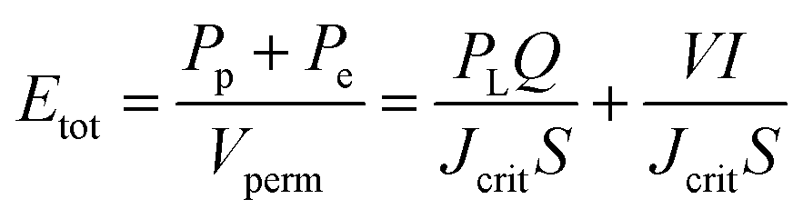
| Fig. 5 Membrane performance in dead-end mode under 1, 2, and 3 bar: (a) permeate flux, (b) final oil rejection percentages (%). | ||
Considering that increasing pressure leads to an increase in pump power consumption, selecting very high pressures would not be economically viable. The optimal pressure should be chosen in a way that both membrane flux and oil rejection factors are acceptable. Since high-pressure differentials result in the accumulation of a gel layer on the membrane surface and a decrease in the permeate flux over time, applying excessively high pressure as the driving force incurs high costs and reduces the lifespan of membrane performance. Therefore, based on the conducted experiments, a pressure of 2 bar was selected as the preferred pressure for further investigations.
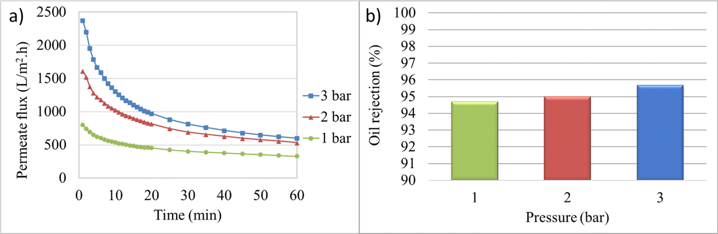
Fig. 6 illustrates the variations in permeate flux over time and the final oil rejection percentage at different crossflow velocities. In general, the permeate flux decline decreases with increasing cross-flow velocity over time. The crossflow velocity of zero, or microfiltration under dead-end conditions, has the lowest permeate flux and the highest membrane fouling. With increasing velocity, a decrease in fouling can be observed by the decreasing slope of the permeate flux curve over time. The initial and final permeate flux values at velocities of 0 and 1.454 m s−1 are 1613.59 and 1715.18 LMH, and 534.04 and 1183.51 LMH, respectively. The decrease in oil rejection percentage from 95% to 94.4% with increasing crossflow velocity from 0 to 1.454 m s−1 is attributed to turbulent flows that prevent the formation of a cake layer, which acts as a barrier for impurity passage, due to the removal of materials that can deposit on the membrane surface. Additionally, due to increased mass transfer, the possibility of oil particle passage increases, resulting in reduced membrane rejection and separation percentage.
 | ||
| Fig. 6 Membrane performance at 2 bar and cross-flow velocities of 0, 0.727, and 1.454 m s−1: (a) permeate flux, (b) final oil rejection percentages (%). | ||
The selected crossflow velocity in this stage is used in the subsequent stages as well. In the electrofiltration process, due to the accumulation of pollutant particles (in this case, crude oil particles) on the titanium anode electrode, there is no need for high flow velocity to minimize cake formation. Increasing the velocity in the electrofiltration process is detrimental and causes the pollutants to flow towards the membrane.62 Taking into account the aforementioned factors, as well as the permeate flux, separation percentage, and energy consumption, the selected crossflow velocity for further tests was 0.727 m s−1.
 | ||
| Fig. 7 Reduction of permeate flux over time for oily water emulsion at different fouling models: (a) complete blocking, (b) intermediate blocking, (c) cake filtration, and (d) standard blocking. | ||
For the treatment of oily water emulsion, the values of R2 for complete blocking, intermediate blocking, cake filtration, and standard blocking models are 0.89, 0.94, 0.97, and 0.92, respectively. A higher value of R2 indicates a better fit of the model. Therefore, the cake filtration and intermediate fouling models exhibit the best agreement with the permeate flux reduction data. In these mechanisms, particles accumulate on the membrane surface and form a cake layer. These types of fouling are reversible.
 | ||
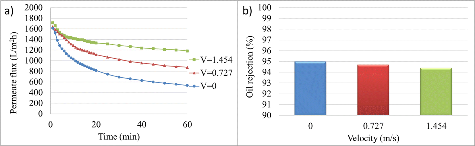
| Fig. 8 Membrane performance in oily water filtration at a pressure of 2 bar and a flow velocity of 0.727 m s−1, before and after a 15 minutes backwashing. | ||
As shown in Fig. 8, the initial permeate flux was recovered to approximately 76% of the initial flux after a 15 minutes backwashing. However, this incomplete recovery of permeate flux with backwashing after one operating cycle necessitates the use of other methods to reduce fouling and increase membrane lifespan.
3.4. Electrofiltration
 | ||
| Fig. 9 Variation of permeate flux with changing voltage for oily water emulsion. Ecrit is indicated by a red ellipse on the graph. | ||
As the voltage increases, the permeate flux rises, from 877.63 LMH at 0 V to 1978.84 LMH at 50 V. Since the oil particles in the feed have a negative charge, increasing the electric field intensity results in a higher electrostatic force acting on the particles. When this force overcomes the other forces acting on the particles that contribute to fouling, it causes them to move away from the membrane surface. As a result, fouling caused by these particles is reduced, and the flux increases. Additionally, according to the Smoluchowski equation, the electroosmotic velocity also increases with the electric field intensity. Therefore, increasing the electric field intensity leads to an enhancement of both electrophoresis and electroosmosis phenomena. However, at a certain electric field intensity (Ecrit), the slope of the flux variation decreases. For example, the permeate flux reached 2009.60 LMH at 60 V, showing only a slight increase compared to 50 V. Ecrit arises due to the limitation in the number of particles that the electric field can displace. According to Fig. 9, the critical electric field intensity in the experimental conditions falls within the range of 50 to 55 V. When the electric field intensity exceeds the critical range, further increases, although resulting in a linear increase in permeate flux, have a minimal effect due to the low slope of the flux variations. Therefore, operating the system at electric field intensities higher than Ecrit is not economical.
Ecrit can also be theoretically calculated using eqn (3). The flux of distilled water at a pressure of 2 bar and a velocity of 0.727 m s−1 increases to 83.1975 LMH with increasing mass transfer velocity. Thus, considering the electrophoretic mobility of oil particles at 3.96 (μm s−1) (V cm−1)−1, Ecrit will be at 55.5 V. The obtained value for Ecrit from both experimental and theoretical approaches is close to each other and confirms one another. Hence, to investigate the effect of the electric field on the performance of the synthesized membrane, voltages of 15, 25, 45, and 65 V were utilized. Based on the measured potential, indicating the negative charge of the particle, and to enhance the membrane performance, the anode was placed on the feed side, while the cathode was placed on the permeate side.
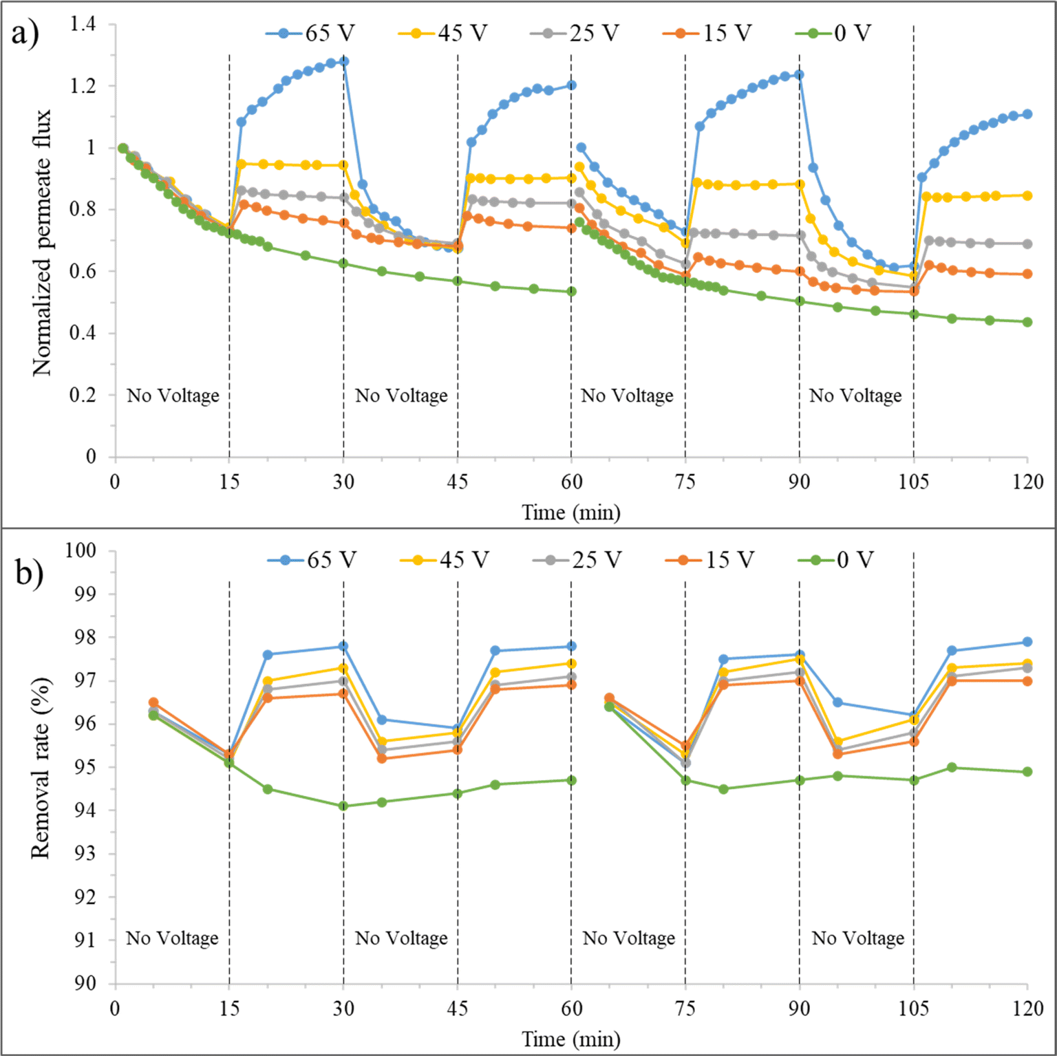 | ||
| Fig. 10 a) Normalized permeate flux and (b) removal rate over time for the synthesized membrane at 0 mM salt concentration, before and after backwashing, under varying voltages. | ||
In the third 15 minutes interval (30–45 minutes), where only filtration is present again, the membrane permeate flux decreases after discontinuing the application of voltage but is still higher than the state without an electrical field. At minute 45, the J/J0 is about 69% and 57% for the combined filtration and electrofiltration and only filtration processes, respectively. This indicates that applying voltage to the membrane is beneficial for improving the permeate flux. When E < Ecrit, oil particles are not completely removed during the electrofiltration process. Therefore, a weak cake layer exists on the membrane surface, which protects the membrane from severe fouling. At the beginning of the third 15 minutes interval, for 65 V and when E > Ecrit, the membrane permeate flux decreases significantly due to the absence of deposition and accumulation of contaminants, reaching its initial value.
In the fourth 15 minutes interval (45–60 minutes), with the reapplication of the electric field, the membrane permeate flux increases in all voltages. At minute 60, for voltages of 15, 25, 45, and 65 V, the J/J0 ratio is 74%, 82%, 90%, and 120%, respectively. However, the relative fluxes are lower than the values in the second 15 minutes interval. This is because electrophoresis has difficulty reducing the accumulation of oil particles inside the membrane pores during the electrofiltration process. Therefore, over time, the permeate flux of the membrane decreases.
The graphs after backwashing of the membrane for different voltages are also shown in Fig. 10. In the absence of an electric field, as previously mentioned, 76% of the initial flux was recovered. When an electric field is applied, it is observed that this initial recovery percentage improves. At voltages of 15, 25, 45, and 65 V, the permeate flux recovery was 80%, 86%, 94%, and 100%, respectively. At 65 V, above Ecrit, due to the effective removal of particles from the membrane surface and reduced membrane fouling, full recovery was achieved after reverse cleaning of the membrane. However, the membrane performance slightly decreased (approximately 3% reduction from minute 90 to 30), likely because after cleaning, we have a new membrane with different performance characteristics.
The effect of applying an electric field on the fouling removal rate is shown in Fig. 10(b). Generally, increasing the fouling layer thickness leads to a decrease in permeate flux but improves fouling mitigation. Despite the smaller average pore size of the membrane compared to oil droplets, larger pores may allow the passage of some small oil droplets, initially reducing oil removal efficiency. Over time, the clogging of membrane pores by oil particles during filtration leads to pore size reduction and improved fouling mitigation. This trend can be observed in the removal rate graph for the zero-voltage condition. The fouling removal rate at minute 60 without an electric field is 94.7%. Applying an electric field and particle detachment from the membrane surface showed improved fouling mitigation. At minute 30, fouling removal rate percentages of 96.7%, 97%, 97.3%, and 97.8% were achieved for voltages of 15, 25, 45, and 65 V, respectively. Upon turning off the electric field, due to the increased cake layer thickness and the clean membrane surface, a decrease in fouling removal rate followed by an increase was observed in the third 15 minutes (30–45 minutes) interval. In the case of 65 V, due to the complete cleanliness of the membrane surface, the fouling removal rate variations follow a similar trend to the first 15 minutes interval. By reapplying the electric field in the fourth stage, the fouling removal rate increased, but not as much as in the second 15 minutes interval.
Due to the reduction in pore size caused by the presence of oil particles inside the pores and the ineffectiveness of backwashing on them, the fouling removal rate percentage is slightly higher (95% at minute 60) for the zero electric field condition. However, in the case of applying voltage, there is no significant difference observed. The application of force on oil particles by the electric field and their detachment from the membrane surface reduce their presence on the membrane and result in a consistent fouling mitigation percentage after backwashing.
Based on the performance graphs for the zero electrical field in Fig. 11(a) and (c), the explained different effects in the previous paragraph can be observed in the presence of salt. At a concentration of 1 mM, the membrane performance remains unaffected, but at a higher concentration of 10 mM, a decrease in membrane performance was observed due to increased concentration polarization and a reduction in the thickness of the electrical double layer of oil particles. It is also worth mentioning that the feed flow velocity has a significant impact on this decrease in performance, and severe fouling did not occur. The permeate flux ratio at minute 60 in a concentration of 10 mM has a reduction of 5% compared to lower concentrations. After backwashing at a concentration of 10 mM, a lower recovery rate compared to lower concentrations was also observed. The recovery rates were 74% and 70% for 1 mM and 10 mM, respectively.
 | ||
| Fig. 11 a) Normalized permeate flux and (b) removal rate over time at a 1 mM salt concentration, (c) normalized permeate flux and (d) removal rate over time at a 10 mM salt concentration, before and after backwashing, at different voltages. | ||
The effect of changing salt concentration on the electrofiltration process is also evident in the graphs of Fig. 11(a) and (c). At 1 mM, an improvement in membrane performance was observed with increasing voltage. At minute 30, for the voltages of 15, 25, 45, and 65 V, J/J0 ratios were 74%, 89%, 96%, and 150%, respectively. The increase in electroosmosis due to the presence of salt may be the reason for the increase in these ratios. Additionally, due to the presence of salt, an increase in voltage results in an increase in electrical current, which causes reactions at the anode surface and bubble formation. At lower electrolyte concentrations, the electrical conductivity of the solution is reduced, which limits the current density during electrofiltration. This lower current density decreases the rate of electrochemical reactions, such as water electrolysis, leading to less bubble formation. The reduction in relative flux during the second stage at different voltages indicates a decrease in the influence of the electric field due to bubble formation at the anode surface and in the feed stream, as well as a decrease in zeta potential. This reduction is more pronounced at higher voltages. The highest relative flux ratio at 65 V is 158%, and after that, it reaches 150% at minute 30. The flow velocity, in addition to particle displacement, also causes bubble displacement and their approach to the membrane surface. As a result, the application of an electric field does not significantly improve the filtration. In 10 mM salt concentration, due to the increase in electrical current with increasing salt concentration (from 103.6 mA at 1 mM to 830 mA at 10 mM), more bubbles are formed on the anode surface, leading to a decrease in the electrophoresis phenomenon. Additionally, in this concentration, zeta potential has also decreased further. At minute 30, for voltages of 15, 25, 45, and 65 V, J/J0 ratios were 67%, 71%, 76%, and 77% respectively, showing a decrease compared to 1 mM. Therefore, the membrane flux is determined by the effects of bubbles and electroosmosis, resulting in irregular variations in membrane flux between 1 mM and 10 mM.
The membrane performance after backwashing at different salt concentrations was also examined. Generally, the recovery improved with increasing voltage. At 1 mM, after backwashing, a recovery of 74% was observed in the zero-voltage state, while recoveries of 80%, 87%, 95%, and 99% were achieved at 15 V, 25 V, 45 V, and 65 V, respectively. The flux recovery values for these conditions at 10 mM are lower due to the presence of salt and increased irreversible fouling. These values are 70%, 73%, 76%, 80%, and 83% for voltages of 0 V, 15 V, 25 V, 45 V, and 65 V, respectively.
Fig. 11(b) and (d) illustrate the changes in removal rate percentage with time and voltage for salt concentrations of 1 and 10 mM. With an increase in salt concentration, due to increased fouling, an improvement in removal rate percentage was achieved, from 94.8% at 1 mM to 95% at 10 mM. Additionally, removal rate percentages at voltages of 15, 25, 45, and 65 V at minute 30, for 1 mM, are 96.2%, 97.3%, 97.5%, and 98.1%, respectively, and for 10 mM, they are 95.6%, 95.8%, 96.1%, and 96.4%, respectively. The presence of bubbles and the reduction in electrophoretic effects are the reasons for the decrease in removal rate percentage at 10 mM. By interrupting the voltage at 1 mM, the oil particle removal rate initially decreases and then slightly increases in the graphs for 15, 25, 45, and 65 V. The reason is that in lower electrolyte concentrations, due to the lesser effect of bubbles formed on the anode and feed side, contaminants can be easily expelled from the membrane surface, and after voltage interruption, contaminants gradually reattach to the membrane surface. In contrast, at 10 mM, after the current interruption, the removal rate percentage increases with increasing voltage, which confirms the formation of bubbles due to increased electric current, reduction in electrophoretic effects, and increased fouling. At minute 45, the removal rate percentages are 96%, 96.1%, 96.5%, and 97.3% for voltages of 15 V, 25 V, 45 V, and 67 V, respectively. As evident, the membrane performance in terms of permeate flux and removal rate percentage is better when voltage is applied at 1 mM compared to 10 mM. Generally, the removal rate percentages after backwashing at 10 mM are higher than at 1 mM. This higher value indicates a higher irreversible fouling at higher salt concentrations, even in the presence of applied voltage.
3.5. Energy consumption
Fig. 12 shows the energy consumption graphs in terms of applied voltages for solutions with different electrical conductivities in the electrofiltration process. At low conductivity, the energy consumption in the applied voltage range in this study decreases. In the salt-free condition, the energy consumption has decreased from 3.88 kW h m3 in the no-voltage condition to 2.71 kW h m3 at 65 V. However, as the conductivity increases, there is a minimum value for energy consumption where the electric field intensity is optimal. In the graph for 1 mM, there is no significant increase in energy consumption up to 25 V voltage, but after that, there is a noticeable increase. As observed, with a further increase in the electrical conductivity of the solution, the energy consumption increases significantly, and it will not be economical to use it.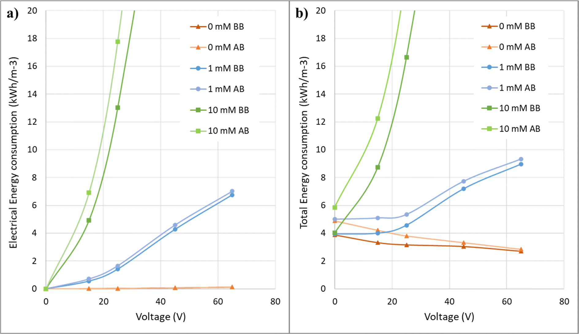 | ||
| Fig. 12 Energy consumption as a function of voltage for different salt concentrations before (BB) and after (AB) backwashing of the membranes: (a) electrical energy consumption, (b) total energy consumption. | ||
The post-backwashing graphs in Fig. 12 for different concentrations indicate that the specific energy consumption trend concerning voltage in these graphs is similar to the pre-backwashing state. However, these graphs for 0 mM and 1 mM concentrations are closer to their pre-backwashing graphs compared to the 10 mM concentration. This once again confirms that at higher salt concentrations, there is greater fouling and less effect of the electric field. Additionally, since the pre and post-backwashing graphs are closer to each other at lower salt concentrations, the membrane process design with these concentrations encounters less error and provides results with lower uncertainty.
4. Conclusions
In conclusion, this study investigated the potential of ceramic membrane-based electrofiltration for the treatment of oily water. The synthesized secondary mullite membrane exhibited favorable characteristics, including high permeate flux (534 LMH) and biaxial flexural strength (75.21 MPa), while maintaining cost-effectiveness. Optimization of operational parameters, such as pressure (2 bar) and cross-flow velocity (0.727 m s−1), resulted in desirable permeate flux and oil removal rates. Using only filtration, backwashing with distilled water resulted in a 76% recovery of membrane initial performance. The critical electric field intensity (Ecrit) range of 50 to 55 V was determined, guiding the selection of optimal voltages for electrofiltration and mitigating fouling through various electrokinetic phenomena. Higher salt concentrations were found to increase fouling and reduce electric field effectiveness. Energy consumption analysis revealed reduced energy requirements at low electrical conductivities, reaching 2.71 kW h m3 at 65 V for the salt-free condition. However, higher electrical conductivity led to increased energy consumption, limiting practical viability. Overall, careful control of operational parameters, particularly voltage, enabled significant improvements in permeate flux, fouling removal rates, and energy efficiency.While this study focused on simulating associated water from crude oil production, the pH of the feed solution is another crucial factor influencing electrofiltration performance and membrane fouling. Future research should address this by investigating the effects of pH, oil compositions, and higher salinity levels to provide a more comprehensive understanding of the process. Additionally, exploring long-term performance, scaling up the process, and evaluating economic feasibility are essential steps towards commercial implementation. Advancements in membrane materials and electrofiltration technology could lead to more efficient and sustainable solutions for oily water treatment, benefiting broader environmental and industrial applications.
Data availability
The data supporting this article have been included as part of the ESI.†Conflicts of interest
There are no conflicts to declare.References
- Y. Gao, G. Xu, P. Zhao, L. Liu, E. Zhang and S. Jin, Ceram. Int., 2023, 49, 32727–32738 CrossRef CAS.
- B. S. Al-anzi and O. C. Siang, RSC Adv., 2017, 7, 20981–20994 RSC.
- M. Rashad, G. Logesh, U. Sabu and M. Balasubramanian, J. Membr. Sci., 2021, 620, 118857 CrossRef.
- A. Salahi, A. Gheshlaghi, T. Mohammadi and S. S. Madaeni, Desalination, 2010, 262, 235–242 CrossRef.
- M. A. Al-Kaabi, N. Zouari, D. A. Da'na and M. A. Al-Ghouti, J. Environ. Manage., 2021, 290, 112527 CrossRef PubMed.
- J. Coca, G. GutiÉRrez and J. Benito, Treatment Of Oily Wastewater, Water Purification and Management, Springer Netherlands, 2011, pp. 1–55 Search PubMed.
- H. Abadikhah, C.-N. Zou, Y.-Z. Hao, J.-W. Wang, L. Lin, S. A. Khan, X. Xu, C.-S. Chen and S. Agathopoulos, J. Eur. Ceram. Soc., 2018, 38, 4384–4394 CrossRef.
- S. F. Ahmed, M. Mofijur, S. Nuzhat, A. T. Chowdhury, N. Rafa, M. A. Uddin, A. Inayat, T. M. I. Mahlia, H. C. Ong, W. Y. Chia and P. L. Show, J. Hazard. Mater., 2021, 416, 125912 CrossRef PubMed.
- C. Zhao, J. Zhou, Y. Yan, L. Yang, G. Xing, H. Li, P. Wu, M. Wang and H. Zheng, Sci. Total Environ., 2021, 765, 142795 CrossRef PubMed.
- J.-H. Eom, Y.-W. Kim, S.-H. Yun and I.-H. Song, J. Ceram. Soc. Jpn., 2014, 122, 788–794 CrossRef.
- Y. Davoodbeygi, M. Askari, E. Salehi and S. Kheirieh, J. Environ. Manage., 2023, 335, 117577 CrossRef PubMed.
- P. S. Goh, K. C. Wong and A. F. Ismail, Desalination, 2022, 521, 115377 CrossRef.
- S. K. Hubadillah, P. Kumar, M. H. Dzarfan Othman, A. F. Ismail, M. A. Rahman and J. Jaafar, RSC Adv., 2018, 8, 2986–2995 RSC.
- B.-B. Dong, F.-H. Wang, M.-Y. Yang, J.-L. Yu, L.-Y. Hao, X. Xu, G. Wang and S. Agathopoulos, J. Membr. Sci., 2019, 579, 111–119 CrossRef.
- Y. Dong, H. Wu, F. Yang and S. Gray, Water Res., 2022, 220, 118629 CrossRef PubMed.
- Q. Gu, T. C. A. Ng, Y. Bao, H. Y. Ng, S. C. Tan and J. Wang, Chem. Eng. J., 2022, 428, 130456 CrossRef.
- L. Zhu, Y. Dong, L. Li, J. Liu and S.-J. You, RSC Adv., 2015, 5, 11163–11174 RSC.
- S. K. Hubadillah, M. H. D. Othman, T. Matsuura, A. F. Ismail, M. A. Rahman, Z. Harun, J. Jaafar and M. Nomura, Ceram. Int., 2018, 44(5), 4538–4560 CrossRef.
- M. Naseri and M. R. Omidkhah, Ceram. Int., 2023, 49, 23612–23626 CrossRef.
- H. Guo, W. Li and F. Ye, Ceram. Int., 2016, 42, 4819–4826 CrossRef.
- Z. Zhu, Z. Wei, W. Sun, J. Hou, B. He and Y. Dong, Appl. Clay Sci., 2016, 120, 135–141 CrossRef.
- D. Zou, M. Qiu, X. Chen, E. Drioli and Y. Fan, Sep. Purif. Technol., 2019, 210, 511–520 CrossRef.
- S. K. Hubadillah, M. R. Jamalludin, M. H. Dzarfan Othman and Y. Iwamoto, Ceram. Int., 2022, 48, 24157–24191 CrossRef.
- A. Abdullayev, C. Avcioglu, T. Fey, A. Hilger, M. Osenberg, I. Manke, L. M. Henning, A. Gurlo and M. F. Bekheet, Open Ceram., 2022, 9, 100240 CrossRef.
- M. Fu, J. Liu, X. Dong, L. Zhu, Y. Dong and S. Hampshire, J. Eur. Ceram. Soc., 2019, 39, 5320–5331 CrossRef.
- F. Wang, B. Dong, N. Ke, M. Yang, R. Qian, J. Wang, J. Yu, L. Hao, L. Yin, X. Xu and S. Agathopoulos, Ceram. Int., 2021, 47, 8375–8381 CrossRef.
- Z. Zhang, G. Huang, Y. Li, X. Chen, Y. Yao, S. Ren, M. Li, Y. Wu and C. An, Chem. Eng. J., 2022, 427, 131987 CrossRef.
- L. N. Nthunya, M. F. Bopape, O. T. Mahlangu, B. B. Mamba, B. Van der Bruggen, C. A. Quist-Jensen and H. Richards, J. Environ. Manage., 2022, 301, 113922 CrossRef.
- A. Ullah, H. J. Tanudjaja, M. Ouda, S. W. Hasan and J. W. Chew, J. Water Proc. Eng., 2021, 43, 102293 CrossRef.
- R. Campo, M. G. Giustra, M. De Marchis, G. Freni and G. Di Bella, Water, 2017, 9, 581 CrossRef.
- A. Khosravanipour Mostafazadeh, M. Zolfaghari and P. Drogui, J. Water Proc. Eng., 2016, 14, 28–40 Search PubMed.
- T. Y. Chiu and F. J. Garcia Garcia, Sep. Purif. Technol., 2011, 78, 62–68 Search PubMed.
- Y. Shen and A. R. Badireddy, Membranes, 2021, 11, 820 CrossRef PubMed.
- H. M. Huotari, G. Trägårdh and I. H. Huisman, Chem. Eng. Res. Des., 1999, 77, 461–468 CrossRef.
- F. Du, P. Ciaciuch, S. Bohlen, Y. Wang, M. Baune and J. Thöming, J. Membr. Sci., 2013, 448, 256–261 CrossRef.
- J. Huang, Z. Wang, J. Zhang, X. Zhang, J. Ma and Z. Wu, Sci. Rep., 2015, 5, 9268 CrossRef CAS PubMed.
- Q. Zhang, P. Arribas, E. M. Remillard, M. C. García-Payo, M. Khayet and C. D. Vecitis, Environ. Sci. Technol., 2017, 51, 9176–9183 CrossRef CAS.
- J. Sun, C. Hu, T. Tong, K. Zhao, J. Qu, H. Liu and M. Elimelech, Environ. Sci. Technol., 2017, 51, 8544–8551 CrossRef CAS PubMed.
- C. Hu, M. Li, J. Sun, R. Liu, H. Liu and J. Qu, J. Colloid Interface Sci., 2019, 539, 11–18 CrossRef PubMed.
- B. Sarkar and S. De, J. Membr. Sci., 2011, 369, 77–87 CrossRef.
- B. Venkataganesh, A. Maiti, S. Bhattacharjee and S. De, Sep. Purif. Technol., 2012, 98, 36–45 CrossRef.
- R.-Y. Yue, L.-N. Liu, J. Guan, C.-M. Zhang, P.-C. Yuan, S.-G. Wang and X.-F. Sun, Sep. Purif. Technol., 2024, 341, 126880 CrossRef.
- B. Sarkar, S. DasGupta and S. De, J. Membr. Sci., 2008, 307, 268–276 CrossRef.
- W. Song, Y. Su, X. Chen, L. Ding and Y. Wan, Sep. Purif. Technol., 2010, 73, 310–318 CrossRef CAS.
- H.-H. Lee, Y.-H. Weng and K.-C. Li, Sep. Purif. Technol., 2008, 63, 23–29 CrossRef CAS.
- Y. Mo, Y. Li, L. Wang, L. Zhang and J. Li, Water Res., 2023, 239, 120064 CrossRef CAS PubMed.
- J.-P. Chen, C.-Z. Yang, J.-H. Zhou and X.-Y. Wang, Chem. Eng. J., 2007, 128, 177–180 Search PubMed.
- C. Aoude, N. Grimi, H. El Zakhem and E. Vorobiev, Separations, 2022, 9, 410 CrossRef.
- B. Sarkar, J. Food Process. Preserv., 2015, 39, 1372–1384 CrossRef.
- B. A. Agana, D. Reeve and J. D. Orbell, Water Res., 2012, 46, 3574–3584 CrossRef.
- T. Y. Chiu, Sep. Sci. Technol., 2013, 48, 84–92 CrossRef.
- H. Kyllönen, PhD thesis, Lappeenranta University of Technology, 2005.
- M. Naseri, M. R. Omidkhah and S. F. Mousavi, Advanced electro-assisted filtration of crude oil/water using a conductive mullite whiskers membrane, J. Environ. Chem. Eng., 2024, 12(5), 114060 CrossRef.
- A. Abdullayev, F. Zemke, A. Gurlo and M. F. Bekheet, RSC Adv., 2020, 10, 31180–31186 RSC.
- K. Suresh, G. Pugazhenthi and R. Uppaluri, J. Water Proc. Eng., 2016, 13, 27–43 CrossRef.
- S. Pourziad, M. R. Omidkhah and M. Abdollahi, Can. J. Chem. Eng., 2019, 97, 1581–1588 CrossRef CAS.
- N. Malik, V. K. Bulasara and S. Basu, Ceram. Int., 2020, 46, 6889–6898 CrossRef CAS.
- H. Jacques, Constant Pressure Blocking Filtration Laws – Application To Power-law Non-newtonian Fluids, Trans. Inst. Chem. Eng., 1982, 60(3), 183–187 Search PubMed.
- P. Geng and G. Chen, J. Membr. Sci., 2016, 498, 302–314 CrossRef CAS.
- H. M. Huotari, I. H. Huisman and G. Trägårdh, J. Membr. Sci., 1999, 156, 49–60 CrossRef CAS.
- D. Elzo, I. Huisman, E. Middelink and V. Gekas, Colloids Surf., A, 1998, 138, 145–159 CrossRef CAS.
- H. M. Huotari and M. Nyström, Trans. Filter Soc., 2000, 1, 17–22 CAS.
Footnote |
| † Electronic supplementary information (ESI) available. See DOI: https://doi.org/10.1039/d4ra05193a |
| This journal is © The Royal Society of Chemistry 2024 |