 Open Access Article
Creative Commons Attribution 3.0 Unported Licence
Fabrication of a free-standing Ti3C2Tx-PTh counter electrode via interfacial polymerization for dye-sensitized solar cells†
Suruthi Priya Nagalingam a,
Saravanan Pandiarajb,
Khalid E. Alzahrani
 c,
Abdullah. N. Alodhayb
 c and
Andrews Nirmala Grace
 *a
*a
aCentre for Nanotechnology Research, Vellore Institute of Technology, Vellore 632014, India. E-mail: anirmalagladys@gmail.com
bDepartment of Self-Development Skills, King Saud University, Riyadh, 11451, Saudi Arabia
cDepartment of Physics and Astronomy, College of Science, King Saud University, Riyadh, 11451, Saudi Arabia
First published on 31st July 2024
Abstract
The current work involves the fabrication of a MXene-Polythiophene (Ti3C2Tx-PTh) composite via interfacial polymerization, alongside its deployment as a counter electrode (CE) or photocathode in dye-sensitized solar cells (DSSCs). The structural properties of the synthesized materials were investigated through a comprehensive array of techniques, including X-ray diffraction (XRD), fourier-transform infrared (FT-IR) spectroscopy, high resolution scanning electron microscopy (HRSEM), energy-dispersive X-ray analysis (EDAX), and X-ray photoelectron spectroscopy (XPS). The electrochemical performance, assessed via cyclic voltammetry (CV) and electrochemical impedance spectroscopy (EIS), revealed that the Ti3C2Tx-PTh CE exhibits superior electro-catalytic activity, and reduction in charge transfer resistance compared to other individual CEs. These observations are in concordance with the data obtained from Tafel analysis. The incorporation of Ti3C2Tx sheets into the composite significantly augmented its catalytic efficacy for triiodide reduction, manifesting in elevated short-circuit photocurrent density and enhanced fill factor metrics. A DSSC utilizing the Ti3C2Tx-PTh CE exhibited a power conversion efficiency (PCE) of 5.83%, which stands on par with that of traditional Pt CEs. Thus, the Ti3C2Tx-PTh CE material is posited as a viable, cost-efficient alternative to Pt, heralding a new era in the engineering of counter electrodes for the next generation of DSSCs.
1. Introduction
The pressing need to address the impacts of climate change and meet the growing global energy demand requires a revolutionary shift in energy production systems. Solar energy, renowned for its renewable, pristine, and limitless characteristics, emerges as a possible remedy in the quest for a low-carbon economy.1–3 Since their invention in 1991 by Gratzel's group, dye-sensitized solar cells (DSSCs) have become a viable third-generation choice among several solar cell technologies, known for their cheap cost, high efficiency, and simple production procedure.4,5 DSSCs generally consist of the following components: a photocathode, a dye-sensitized titanium dioxide (TiO2) photoanode, coupled with an electrolyte comprising a redox pair of iodide and triiodide redox pair.6 The counter electrode (CE) is of utmost importance as it facilitates the catalytic reduction of triiodide ions by collecting electrons from the external circuit. Due to its outstanding catalysis and electron exchange properties, platinum (Pt) has long been considered the gold standard for CE materials; yet, the high cost and limited availability of Pt are formidable obstacles to the commercialization and mass adoption of DSSCs.7,8 As a result of this constraint, investigations have been initiated into non-Pt CE materials that are environmentally friendly and cost-effective, and which can match or surpass the performance of Pt.9,10 To replace Pt, a number of contenders have showed promise, including composites, metal alloys,11 carbon-based materials,12,13 transition metal compounds,14 and conductive polymers.15,16 These developments are in line with the worldwide movement towards renewable energy sources and represent a larger effort to create DSSCs with improved environmental sustainability, lower prices, and greater power conversion efficiencies (PCE).MXenes (Ti3C2Tx), characterized by their two-dimensional (2D) structures of transition metal nitrides, carbonitrides, and carbides have emerged as prominent materials in energy storage and conversion technologies.17,18 These materials boast significant surface area, high electrical conductivity, a wide range of compositions, and the ability to undergo surface modifications. The layered structure of Ti3C2Tx, coupled with their excellent ion intercalation capability, thermal stability, flexibility, and modifiable surface terminal groups (such as hydroxyl, oxygen, and fluorine), renders them a focal point of research across various domains, including wearable electronics, supercapacitors, photovoltaics, and more.17,19–24 In the domain of third-generation photovoltaic technologies, Ti3C2Tx have shown considerable promise in enhancing the efficiency of DSSCs, perovskite solar cells (PSCs), and quantum dot solar cells (QDSCs).25 This enhancement is primarily attributed to Ti3C2Tx ability to stabilize the perovskite layer, improve charge carrier mobility, and adjust work functions at different interfaces, including photoanodes, hole transporting layers, and CEs. Notably, Ti3C2Tx have been utilized as additives in mesoporous TiO2-based photoanodes for DSSCs, significantly improving charge transfer and light scattering capabilities, thereby augmenting light-harvesting and electron collection efficiencies.26,27 Furthermore, the conductive nature of Ti3C2Tx offers an economically viable and stable alternative to Pt CEs, overcoming the latter's cost and instability challenges in acidic environments. Recent advancements have showcased the potential of Ti3C2Tx to surpass conventional Pt-based CEs in terms of PCE. Innovations such as hydrothermal deposition of CoS on Ti3C2Tx and the creation of CoS/Ti3C2Tx CE through ion-exchange techniques have led to significant improvements in electrocatalytic properties and PCE of 8.0%.28 Additionally, incorporating carbon nanotubes (CNTs) to prevent agglomeration has yielded structures with optimal ratios of CoMoP2 and Ti3C2Tx, achieving remarkable PCE enhancements of 10.64%.29 These developments highlight Ti3C2Tx as cost-effective, high-performing, and stable Pt-free alternatives for CEs in DSSCs. However, challenges such as charge trapping within MXene's multilayered structure and van der Waals force-induced stacking, which hinder electron transport and reduce specific surface area and conductivity, remain.8,30 To address these issues, surface modification with conductive polymers like polyaniline (PANI), polypyrrole (PPy), and particularly polythiophene (PTh) and its derivatives has been proposed.31 These modifications aim to improve electrochemical performance and stability by preventing stacking and enhancing the electroactive surface area. A novel approach involving the integration of PTh nanoparticles between Ti3C2Tx nanosheets has been explored, resulting in the creation of Ti3C2Tx-PTh hybrid. This method, which involves liquid–liquid interfacial polymerization, offers a simple and room-temperature process for producing high-molecular-weight polymers.32 The resulting Ti3C2Tx-PTh hybrid manifests considerable potential as a CE material for the first time, amalgamating the advantageous properties of its constituent materials. The physicochemical characteristics of the composite, alongside its photovoltaic performance metrics, were systematically delineated. DSSCs fabricated utilizing the Ti3C2Tx-PTh as the CE, have demonstrated an PCE to 5.82%, equivalently efficacious to that of conventional Pt CE.
2. Experimental methods
2.1 Synthesis of Ti3C2Tx nanosheets
In a meticulously controlled experimental procedure, approximately 0.5 grams of the MAX phase material, Ti3AlC2, was subjected to an etching regimen utilizing a 30 ml of 40% hydrofluoric acid solution over a span of two days. This etching treatment was succeeded by multiple centrifugation cycles, interspersed with thorough washes using deionized water, to facilitate the isolation of ml-Ti3C2Tx. Subsequently, the resultant mixture underwent vacuum filtration, followed by a drying phase at 60 °C for an extended period.2.2 Synthesis of Ti3C2Tx-PTh CE
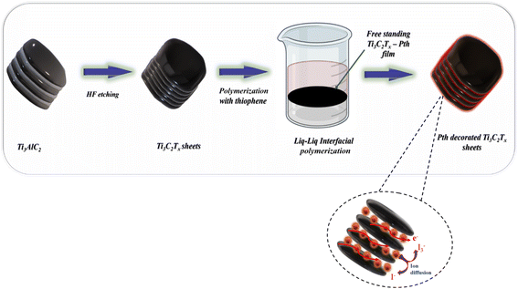
As shown in Fig. 1 the fabrication of the Ti3C2Tx-PTh hybrid was developed via a liquid–liquid interfacial polymerization method. The process of liquid–liquid interface polymerization was initiated by first preparing an aqueous solution containing a predetermined quantity of 0.3 g of ferric chloride hexahydrate, and 0.05 g of Ti3C2Tx, ultrasonically disseminated within 15 ml of distilled water. Following this, the monomeric solution was prepared by thoroughly mixing 0.5 ml of thiophene into 15 ml of chloroform to form the organic solvent phase, an essential step in the process. The aqueous solution was then meticulously added to the organic solution in a dropwise manner, ensuring minimal disturbance to the resultant mixture, which was then left to stand undisturbed for a duration of 24 hours. During this quiescent period, a notable phenomenon was observed wherein a black film gradually emerged at the interface between the aqueous and organic phases, indicating the successful formation of a polymerized film. This observation underscores the critical nature of the interface in facilitating the polymerization process. The culmination of this synthesis process involved the purification of the resultant polymeric material through sequential ethanol washes and subsequent drying at 60 °C for 24 hours. For comparative analysis, PTh was synthesized employing the same methodology, albeit in the absence of the Ti3C2Tx.2.3 DSSC construction and assembly using various CEs
The cleaning regimen for fluorine-doped tin oxide (FTO) glass substrates incorporated an initial sonication in a detergent solution, followed by successive washings with deionized water, acetone, and isopropanol, ensuring a pristine surface for subsequent processing. The fabrication of the TiO2 photoanode commenced with the preparation of a viscous paste, constituted of 230 mg TiO2 (P25) nanoparticles, 230 μl deionized water (DI), 10 μl of conc. nitric acid (HNO3), and 10 μl Triton-X. This paste was meticulously applied onto a pre-cleaned FTO surface through the application of the doctor blade method, ensuring a uniform layer over a defined area of 4 mm by 4 mm. Subsequent thermal treatment involved sintering the coated substrate at 450 °C for a period of 30 minutes to foster enhanced adhesion properties, followed by a natural cooling process to reach ambient temperature conditions. In the subsequent stage, a dye solution was formulated by dissolving 0.3 mM of the N719 dye in ethanol. The previously prepared TiO2 layer was immersed in this solution for an extended duration, specifically overnight, to ensure comprehensive adsorption of the dye molecules. To remove any non-adsorbed dye, the electrode was rinsed with ethanol. CEs, including variants such as Ti3C2Tx, PTh, and a Ti3C2Tx-PTh hybrid, were fabricated by creating a thick slurry of the respective CE materials dispersed in an N-methyl-2-pyrrolidone medium. This paste was then evenly applied to a precleaned FTO surface using the doctor blade method, targeting an area specification of 4 mm by 4 mm. A sintering process at 80 °C for one hour was then employed, allowing the substrates to gradually return to room temperature. A Pt CE was also prepared by dispersing 10 mM hexachloroplatinic acid in isopropyl alcohol and applying this dispersion to a similar-sized area on the FTO, which was subsequently sintered at 450 °C for a period of 30 minutes before being allowed to cool to ambient temperature. The electrolyte solution for the DSSC was prepared by combining 0.05 M iodine (I2), 0.5 M lithium iodide (LiI), and 0.1 M 4-tert-butylpyridine in acetonitrile. Assembly of DSSCs entailed positioning the dye-loaded TiO2 as the photoanode and the various prepared CEs, with the entire setup secured together. The final step in the assembly process involved the careful injection of the iodide/triiodide electrolyte between the electrodes, completing the DSSC construction.3. Results and discussion
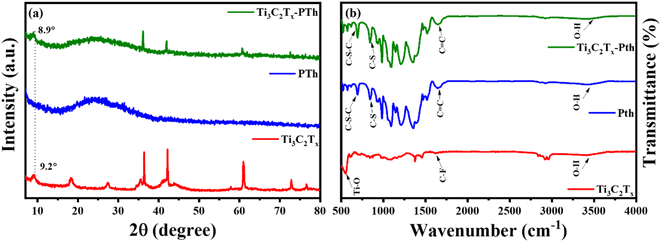
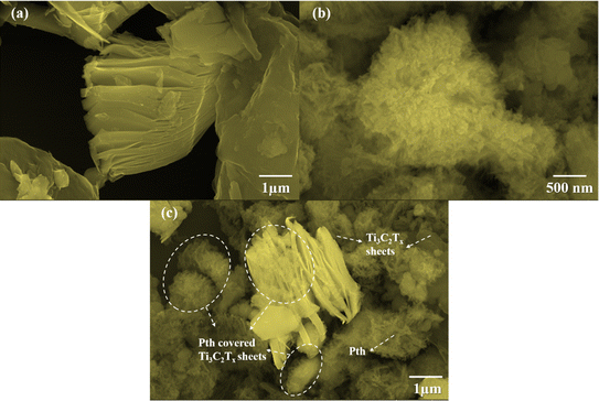
The elucidation of structural modifications in Ti3C2Tx through powder XRD analysis highlights significant findings, particularly concerning the crystalline structure alterations post HF etching as shown in Fig. 2(a). Notably, the observed reduction in the peak intensity at 38.9°, which is associated with the (104) plane of Ti3AlC2, signifies the transition to Ti3C2Tx. This transformation is evidenced by the pronounced decrease in peak intensity, suggesting the removal of the Al layer and thus, confirming the conversion from the MAX phase to MXene, as supported by existing literature.33,34 Additionally, the alteration in the positions of the (002) peak from 9.5° to 9.2° is indicative of an increase in interlayer spacing, further validating the successful etching process.35,36 For the analysis of pristine PTh, its XRD pattern presents a broad peak around 22°, reflecting its amorphous nature. When considering the Ti3C2Tx-PTh hybrid, the XRD analysis reveals both the broad peak corresponding to PTh and a distinct peak indicative of Ti3C2Tx. The shift of the Ti3C2Tx peak from 9.2° to 8.9° in the composite suggests an effective exfoliation of Ti3C2Tx within the PTh matrix, leading to an increased d-spacing.33,37 This observation underscores the successful integration of Ti3C2Tx into the PTh matrix through interfacial polymerization, marking a notable structural adaptation and highlighting the intricate interfacial interactions within the composite material. The identification of functional groups within the CE materials was examined via Fourier-transform infrared spectroscopy (FT-IR), further enriched by a meticulous analysis of their compositional and structural aspects through the discernment of specific functional group peaks. FT-IR spectral analysis delineated in Fig. 2(b) for Ti3C2Tx, PTh, and the Ti3C2Tx-PTh composite revealed distinctive spectral phenomena. For PTh, the spectral analysis identified peaks at 692 cm−1, and 830 cm−1, which are attributable to C–S–C bending vibrations, and C–S stretching, respectively.38–40 These observed peaks corroborate the existence of thiophene rings, thereby confirming the efficacious synthesis of PTh.40 In the Ti3C2Tx spectrum, an eminent peak at 3440 cm−1 was indicative of –OH stretching vibrations, denoting a significant presence of hydroxyl (–OH) groups on the Ti3C2Tx nanosheets. Peaks observed at 570 cm−1 and 1621 cm−1 were correlated with Ti–O and C–F bonds, respectively, accentuating the presence of these functional groups within the Ti3C2Tx framework.40 In the spectrum for the Ti3C2Tx-PTh hybrid, absorption peaks characteristic of both constituent materials was identified, demonstrating an extensive integration of PTh into the Ti3C2Tx matrix. Notably, the composite material's spectrum exhibited subtle shifts in peak positions and a diminution in peak intensities in comparison to the pristine PTh spectrum.32 These modifications suggest an effective intercalation of Ti3C2Tx into the polymeric matrix, indicative of alterations in the composite's structural and compositional characteristics and elucidating the intricate interfacial interactions between MXene and PTh within the composite.The investigation of the surface morphologies of Ti3C2Tx, PTh, and their hybrid Ti3C2Tx-PTh was undertaken through High Resolution Scanning Electron Microscopy (HRSEM) as given in Fig. 3(a)–(c). This analysis confirmed that Ti3C2Tx displays a stratified sheet-like morphology. In contrast, SEM observations of PTh revealed a distinct granular form.38 This specific morphology was also detected atop the Ti3C2Tx layers within the composites, indicating a successful adherence and polymerization of PTh onto these sheets. To complement these findings, Energy Dispersive Spectroscopy (EDS) elemental mappings were employed, showcasing a uniform distribution of the S element across the Ti3C2Tx structures as shown in Fig. S1 and S2.† This distribution mirrors the SEM results, underscoring an even spread of PTh throughout the composite material. In essence, the combined SEM and EDS investigations elucidate a porous architecture within the Ti3C2Tx-PTh composite, facilitating effective ion and electron transport. This structure is attributed to the various functional groups serving as nucleation points during PTh's polymerization on the Ti3C2Tx sheets. Therefore, the synthesized composite material is characterized by an expansive surface area and multiple pathways for electrolyte ions, positioning it as a promising candidate for utilization in diverse electrochemical systems.
X-ray Photoelectron Spectroscopy (XPS) was employed to delve into the bonding states and surface chemical composition of the Ti3C2Tx-PTh hybrid, revealing significant insights as observed in Fig. 4(a)–(d). The XPS spectra exhibited notable peaks for Ti 2p, C 1s, S 2p, O 1s, and F 1s, evidencing the successful amalgamation of Ti3C2Tx within the Ti3C2Tx-PTh composite. These peaks were indicative of the –O, –OH, and –F functional groups, marking the composite's successful chemical integration. Furthermore, the presence of C 1s and S 2p peaks affirmed the synthesis of the Ti3C2Tx-PTh CE. In the S 2p XPS spectrum, binding energies at 163.9 eV and 168.2 eV were observed for the S 2p3/2 state, and at 164.7 eV for the S 2p1/2 state, alongside a peak at 169 eV indicating S in a positively charged state (Sδ+).41,42 This delineates the integration of thiophene units within the polymer chains, suggestive of polariton and dipolariton formation.43 The Ti 2p XPS spectrum unveiled six distinct peaks between 455 eV, 456.2 eV, 459.7 eV, 461.4 eV, 462.3 eV, and 465.3 eV, each reflecting different titanium bonding within the composite, indicative of Ti–C, C–Ti–O, Ti–O2−x Fx, C–Ti–F2p1/2, C–Ti–O2p1/2 and Ti–Fx.44,45 The C 1s spectrum highlighted four peaks, signifying various carbon bonding such as C–Ti, C–C, and C–O, and O![[double bond, length as m-dash]](https://www.rsc.org/images/entities/char_e001.gif) C–O further elucidating the composite's chemical complexity at 281.6 eV, 284.8 eV, 286.2 eV, and 288 eV.44 The O 1s XPS spectrum, with peaks at 531.5 eV and 532.8 eV, pointed to diverse oxygen-containing functional groups such as C–Ti–(OH)x and C
C–O further elucidating the composite's chemical complexity at 281.6 eV, 284.8 eV, 286.2 eV, and 288 eV.44 The O 1s XPS spectrum, with peaks at 531.5 eV and 532.8 eV, pointed to diverse oxygen-containing functional groups such as C–Ti–(OH)x and C![[double bond, length as m-dash]](https://www.rsc.org/images/entities/char_e001.gif) O, while the F 1s spectrum, with peaks at 685 eV and 685.7 eV, confirmed the presence of Ti–F and C–F bonds as observed in Fig. S3(a) and (b).†46 These results not only verify the PTh integration within the Ti3C2Tx-PTh composite but also shed light on the composite's complex chemical and bonding nature, establishing a foundational understanding for further exploration of its attributes and potential applications.
O, while the F 1s spectrum, with peaks at 685 eV and 685.7 eV, confirmed the presence of Ti–F and C–F bonds as observed in Fig. S3(a) and (b).†46 These results not only verify the PTh integration within the Ti3C2Tx-PTh composite but also shed light on the composite's complex chemical and bonding nature, establishing a foundational understanding for further exploration of its attributes and potential applications.
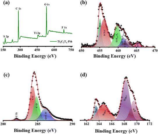 | ||
| Fig. 4 (a) XPS survey spectrum of Ti3C2Tx-Pth, and XPS patterns of (b) Ti 2p, (c) C 1s, and (d) S 1s. | ||
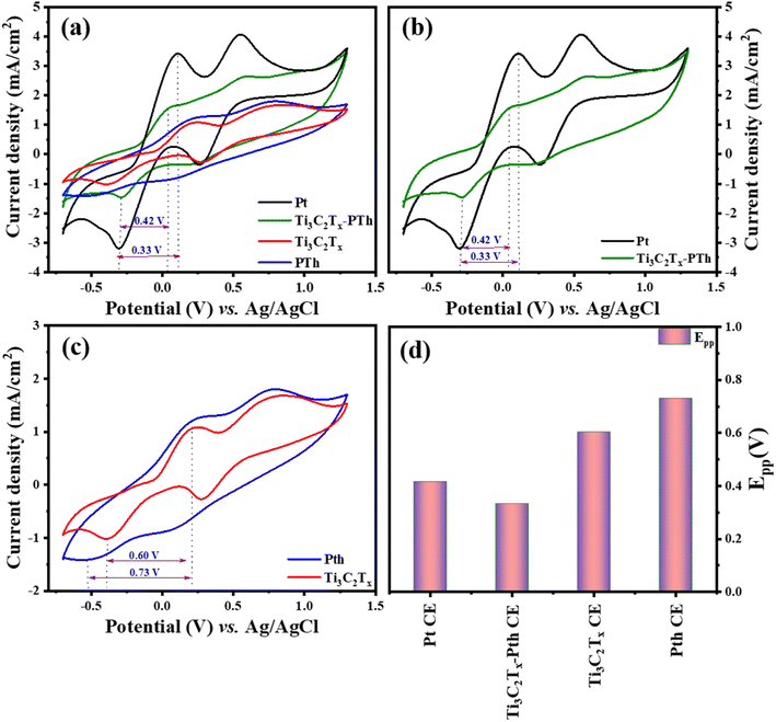
In the quest to delineate the catalytic capabilities and durability of CEs for DSSCs, a methodical investigation was conducted using cyclic voltammetry (CV) within a three-electrode system. This experimental array comprised a platinum (Pt) wire and an Ag/AgCl electrode, serving as the counter and reference electrodes respectively, immersed in an electrolytic medium of 0.01 M LiI, 1.0 mM I2, and 0.1 M LiClO4. The procedure entailed performing CV sweeps in a defined potential from −0.7 to +1.3 V aimed at uncovering the redox dynamics exhibited by the electrodes. The primary focus was to scrutinize the electrochemical attributes of novel counter electrodes in comparison with conventional Pt-CE, with particular emphasis on the redox transformations involving triiodide to iodide and vice versa at a scanning rate of 50 mV s−1. The CV analysis of the Ti3C2Tx-Pth revealed two distinct sets of redox peaks, where the first set was indicative of the I3−/I− redox process and the latter represented the I2/I3− process as given in eqn (1) and (2). The anodic peak observed at higher potentials corresponds to the oxidation of I2 to I−3 as described in eqn (2). Conversely, the cathodic peak at lower potentials corresponds to the reduction of I−3 to I− as outlined in eqn (1). The cathodic peak associated with eqn (1) demonstrates the counter electrode's (CE) catalytic efficiency in reducing triiodide to iodide, represented by the cathodic peak current density. This observation accentuates the Ti3C2Tx-Pth CE's adeptness in catalysing the reduction of I3− to I−, a pivotal reaction within DSSCs.47
| I3− + 2e− → 3I− | (1) |
| 3I2 + 2e− → 2I3− | (2) |
Two distinctive characteristics, such as peak to peak separation (Epp) and peak current density, are used to determine counter electrode catalytic capacity. The peak-to-peak separation can be determined using eqn (3).
| Epp = |Ep(anodic) − Ep(cathodic)| | (3) |
In evaluating the electrochemical parameters of various CEs, the Ti3C2Tx-Pth CE was identified as exhibiting superior peak current density and a diminished peak-to-peak separation potential (Epp) when compared with other alternative CEs. Remarkably, the Ti3C2Tx-Pth CE demonstrated a peak current density of 1.62 mA cm−2 and an Epp of 0.33 V, surpassing the electrochemical performance of both pristine Ti3C2Tx (1.08 mA cm−2, 0.60 V) and pristine Pth (1.24 mA cm−2, 0.73 V), while paralleling that of Pt CE (3.4 mA cm−2, 0.42 V) as observed in Fig. 5(a)–(d). These findings illuminate the reversible conversion of I3− to I−, and superior electrocatalytic activity of the Ti3C2Tx-PTh CE. The performance of Ti3C2Tx CE alone, albeit slightly lower in peak current density compared to PTh, but with a reduced Epp suggests a synergistic amplification upon its integration with polythiophene. This synergy substantially uplifts its electrocatalytic potential towards iodide/tri-iodide electrolytes, leading to a significant improvement in PCE for DSSCs equipped with Ti3C2Tx-PTh CEs.
As demonstrated in Fig. 6(a), there is a notable increase in peak current density concomitant with rising scan rates, signifying an enhancement in the catalytic efficiency of Ti3C2Tx-PTh CE as the scan rate increases. The observation of a uniform, distortion-free pattern throughout these measurements implies a commendable level of reaction reversibility. Furthermore, as seen in Fig. 6(b), Ti3C2Tx-PTh CE's electrochemical endurance was evaluated by subjecting it to CV for 100 cycles at a scan rate of 50 mV s−1 which was replotted at every 10 cycles as given in Fig. 6(c). The remarkable electrochemical stability of the CE was highlighted by the findings, which showed a steady cathodic peak current with no discernible changes in the CV profiles over the test period, suggesting its viability for prolonged use in DSSCs.
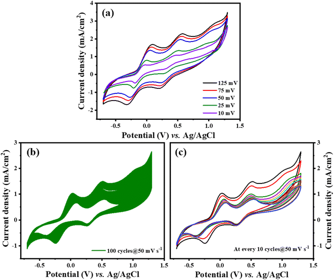 | ||
| Fig. 6 (a) Ti3C2Tx-PTh at various scan rates (b) and (c) stability test of Ti3C2Tx-PTh at 50 mV s−1 for 100 cycles and plotted at every 10 cycles. | ||
Electrochemical impedance spectroscopy (EIS) was utilized to understand the electrocatalytic behavior of the CEs further. The Nyquist plots of the CEs across a frequency range from 0.1 Hz to 100![[thin space (1/6-em)]](https://www.rsc.org/images/entities/char_2009.gif) 000 Hz are depicted in Fig. 7(a), with the relevant parameters outlined in Table 1. The high-frequency region of the Nyquist plots showcases a semicircle that corresponds to the charge transfer resistance (Rct) at the counter electrode's interface, which is crucial in assessing the counter electrode's catalytic efficiency in reducing triiodide ions.47 The inclusion of Ti3C2Tx into the PTh CE was observed to decrease the Rct value from 29.1 Ω to 17.6 Ω, under identical conditions. Additionally, the internal series resistance (Rs), which stems from the combined resistance of the electrolyte and the electrode's sheet resistance, is discernible from the high-frequency real axis intercept in the EIS plots. The Rs for the Ti3C2Tx-PTh CE was recorded at 12.2 Ω, showing a reduction from the 14.66 Ω observed for the solely PTh-based CE and 16.38 Ω for Ti3C2Tx CE. This decline in Rct and Rs suggests an enhanced electrocatalytic performance of the composite electrode over the PTh CE, attributed to the composite electrode's larger electrochemical active surface area enhancing the charge transfer at the Ti3C2Tx-PTh counter electrode/electrolyte interface, thereby accelerating the reduction reaction.48 In comparison, the Pt CE exhibited significantly lower Rct (5.2 Ω) and Rs (11.9 Ω) values than those of the Ti3C2Tx-PTh CE. Given the influence of Rs and Rct on the fill factor (FF) of DSSCs, Pt was shown to achieve a superior FF, as demonstrated in the photovoltaic efficiency tests outlined in Table 1.
000 Hz are depicted in Fig. 7(a), with the relevant parameters outlined in Table 1. The high-frequency region of the Nyquist plots showcases a semicircle that corresponds to the charge transfer resistance (Rct) at the counter electrode's interface, which is crucial in assessing the counter electrode's catalytic efficiency in reducing triiodide ions.47 The inclusion of Ti3C2Tx into the PTh CE was observed to decrease the Rct value from 29.1 Ω to 17.6 Ω, under identical conditions. Additionally, the internal series resistance (Rs), which stems from the combined resistance of the electrolyte and the electrode's sheet resistance, is discernible from the high-frequency real axis intercept in the EIS plots. The Rs for the Ti3C2Tx-PTh CE was recorded at 12.2 Ω, showing a reduction from the 14.66 Ω observed for the solely PTh-based CE and 16.38 Ω for Ti3C2Tx CE. This decline in Rct and Rs suggests an enhanced electrocatalytic performance of the composite electrode over the PTh CE, attributed to the composite electrode's larger electrochemical active surface area enhancing the charge transfer at the Ti3C2Tx-PTh counter electrode/electrolyte interface, thereby accelerating the reduction reaction.48 In comparison, the Pt CE exhibited significantly lower Rct (5.2 Ω) and Rs (11.9 Ω) values than those of the Ti3C2Tx-PTh CE. Given the influence of Rs and Rct on the fill factor (FF) of DSSCs, Pt was shown to achieve a superior FF, as demonstrated in the photovoltaic efficiency tests outlined in Table 1.
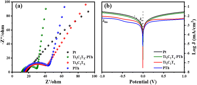 | ||
| Fig. 7 (a) Electrochemical impedance spectra of Pt, Ti3C2Tx, PTh and Ti3C2Tx-PTh CEs made from the symmetrical cell (b) Tafel polarisation of Pt, Ti3C2Tx, PTh and Ti3C2Tx-PTh CEs. | ||
| CEs | Rs (Ω) | Rct (Ω) | Voc (V) | Jsc (mA cm−2) | Fill factor | η |
|---|---|---|---|---|---|---|
| Pt | 12 | 5.2 | 0.66 | 19.27 | 62.7 | 7.9 |
| Ti3C2Tx | 16.38 | 25.2 | 0.66 | 12.6 | 55.3 | 4.61 |
| Pth | 14.6 | 29.1 | 0.66 | 11.6 | 55.5 | 4.19 |
| Ti3C2Tx-Pth | 12.2 | 17.6 | 0.67 | 15.54 | 56.05 | 5.82 |
The Tafel polarization analysis is utilized as an efficacious method for investigating electrochemical behaviors. Fig. 7(b) delineates the Tafel testing results for varied counter electrodes (CEs), highlighting two pivotal parameters: the exchange current density (Jo) and the maximal diffusion current density (Jlim). Elevated values for these parameters are indicative of superior catalytic performance and enhanced electron diffusion rate.49,50 As represented in Fig. 7(b), the CE with Ti3C2Tx-PTh composition exhibits the most prominent Jo and Jlim values in the Tafel and diffusion segments, measured at −2.8 mA cm−2 and −1.6 mA cm−2, respectively. These values are higher than those of pristine Ti3C2Tx CE, which have Jo and Jlim values of −2.9 mA cm−2 and −2.0 mA cm−2, and PTh CE, which have values of −3.0 mA cm−2 and −2.2 mA cm−2. Additionally, these values are comparable to those of Pt CE, which has Jo and Jlim values of −2.5 mA cm−2 and −1.5 mA cm−2. The observed increase in catalytic efficiency can be attributed to the combined effect of the abundant active sites afforded by Ti3C2Tx and PTh and the efficient electron transport channels. Moreover, the relationship for Jo as specified in eqn (4) is identified to be inversely proportional to the charge transfer resistance (Rct), thereby aligning with the observations derived from the Electrochemical Impedance Spectroscopy (EIS) studies.
 | (4) |
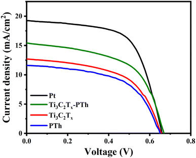 | ||
| Fig. 8 J–V photocurrent density–voltage curves of DSSC fabricated with Pt, Ti3C2Tx, PTh, and Ti3C2Tx-PTh CEs. | ||
| Counter electrodes | Jsc (mA cm−2) | Voc (V) | Fill factor | η | References |
|---|---|---|---|---|---|
| PTh-IrO2 | 10.1 | 0.6 | 50 | 3.01 | 51 |
| Co-SnS2/rGo | 11.85 | 0.77 | 60.1 | 5.54 | 52 |
| MoSe2 | 16.28 | 0.72 | 41 | 4.8 | 53 |
| Carbon black/SnSe | 12.4 | 0.66 | 62 | 5.0 | 54 |
| MXene-rGO | 10.9 | 0.64 | 62 | 4.36 | 55 |
| V2C | 8.07 | 0.76 | 53 | 3.39 | 56 |
| MXene-MoS2 | 11.4 | 0.64 | 71 | 5.21 | 55 |
| Ti3C2Tx-Pth | 15.54 | 0.67 | 56.05 | 5.82 | This work |
To further elucidate the photovoltaic characteristics of DSSCs, the external quantum efficiency (EQE) spectra of DSSCs employing Pt and Ti3C2Tx-PTh CEs are presented in Fig. S4.† The utilization of the same dye results in a consistent spectral response range across all DSSCs. The EQE for DSSCs with Pt CE and Ti3C2Tx-PTh CE peaks at 540 nm, attaining values of 41% and 38%, respectively, which are in close proximity to the performance exhibited by Pt CE. This enhancement in photovoltaic performance is attributable to the synergistic interaction of multiple active sites, superior charge transfer dynamics, and enhanced electrocatalytic activity intrinsic to the Ti3C2Tx-PTh CE.
4. Conclusions
The Ti3C2Tx-PTh composite was synthesized through a liquid–liquid interfacial polymerization technique, subsequently serving as an alternative CE in DSSCs, aiming to replace the Pt CE. Analyses utilizing XRD, FTIR, and XPS confirmed the effective integration of Ti3C2Tx into the PTh matrix. The morphological analysis revealed a consistent dispersal of Ti3C2Tx within the polymer framework. Compared to the pristine Ti3C2Tx CE and PTh CE, the composite electrode exhibited superior electrocatalytic performance, especially in the reduction of triiodide/iodide (I3−/I−), primarily due to its increased active surface area and enhanced charge transport capabilities. The DSSCs with the Ti3C2Tx-PTh CE demonstrated a higher short-circuit current density (Jsc) and fill factor (FF) compared to devices using pure PTh. This improvement is attributed to the inclusion of Ti3C2Tx sheets, which notably enhances electron transport within the PTh matrix by decreasing resistance. Investigation of the photovoltaic performance of the DSSC constructed using Ti3C2Tx-PTh CE revealed a PCE of 5.82%, comparable to devices equipped with Pt CE. Therefore, the Ti3C2Tx-PTh CE material emerges as a viable and effective substitute for the costly Pt CE, marking its potential for future generation CE in DSSCs. This facile synthesis approach could significantly contribute to the development of other Ti3C2Tx-based composite materials for use in economical and efficient photoelectronic devices in the foreseeable future.Data availability
The authors declare that the data supporting the findings are available within the article.Conflicts of interest
The authors declare no competing conflict of interest.Acknowledgements
Author KEA acknowledges Researchers Supporting Project number (RSPD2024R531), King Saud University, Riyadh, Saudi Arabia. The authors acknowledge DST – TDT, India for funding this research work through the project number DST/TDT/AM/2022/75.References
- M. Kokkonen, P. Talebi, J. Zhou, S. Asgari, S. A. Soomro, F. Elsehrawy, J. Halme, S. Ahmad, A. Hagfeldt and S. G. Hashmi, J. Mater. Chem. A, 2021, 9, 10527–10545 RSC.
- A. M. M. Hasan and M. A. B. H. Susan, RSC Adv., 2024, 14, 7616–7630 RSC.
- M. Noman, Z. Khan and S. T. Jan, RSC Adv., 2024, 14, 5085–5131 RSC.
- B. O'regan and M. Grätzel, Nature, 1991, 353, 737–740 CrossRef.
- L. J. V. Gómez, A. L. Iglesias, V. M. Soto, A. O. Sarabia, R. V. Castro, E. A. L. Maldonado, M. T. O. Guzmán, C. A. R. Soto, E. G. L. Medina and J. L. V. Arce, RSC Adv., 2023, 13, 36023–36034 RSC.
- H. V Flint, H. A. R. Tito, R. D. James, F. Cucinotta, E. Gibson and M. E. Q. Caceda, RSC Adv., 2024, 14, 9913–9919 RSC.
- M. Aftabuzzaman, M. S. Ahmed, K. Matyjaszewski and H. K. Kim, Chem. Eng. J., 2022, 446, 137249 CrossRef CAS.
- Z. Hu, Y. Li, A. Li, H.-H. Wang and X.-F. Wang, RSC Adv., 2023, 13, 34808–34816 RSC.
- C. Wu, R. Li, Y. Wang, S. Lu, J. Lin, Y. Liu and X. Zhang, Chem. Commun., 2020, 56, 10046–10049 RSC.
- H.-H. Chen, P.-C. Lin, H.-E. Tsai, W.-Y. Tsao and C.-L. Wang, J. Electroanal. Chem., 2022, 923, 116836 CrossRef CAS.
- Z. Pang, Y. Zhao, Y. Duan, J. Duan, Q. Tang and L. Yu, J. Energy Chem., 2019, 30, 49–56 CrossRef.
- M. Mirzaei and M. B. Gholivand, Sol. Energy, 2022, 242, 212–224 CrossRef CAS.
- K. Wu, S. Liu, Y. Wu, B. Ruan, J. Guo and M. Wu, Sol. Energy Mater. Sol. Cells, 2022, 236, 111503 CrossRef CAS.
- C. Gao, Q. Han and M. Wu, J. Energy Chem., 2018, 27, 703–712 CrossRef.
- M. Kouhnavard, D. Yifan, J. M. D'Arcy, R. Mishra and P. Biswas, Sol. Energy, 2020, 211, 258–264 CrossRef CAS.
- X. Yao, B. He, L. Cui, J. Ti, H. Chen, Y. Duan and Q. Tang, Catal. Commun., 2022, 163, 106403 CrossRef CAS.
- S. J. Kim, H.-J. Koh, C. E. Ren, O. Kwon, K. Maleski, S.-Y. Cho, B. Anasori, C.-K. Kim, Y.-K. Choi and J. Kim, ACS Nano, 2018, 12, 986–993 CrossRef CAS PubMed.
- M. Naguib, M. Kurtoglu, V. Presser, J. Lu, J. Niu, M. Heon, L. Hultman, Y. Gogotsi and M. W. Barsoum, in MXenes, Jenny Stanford Publishing, 2011, pp. 15–29 Search PubMed.
- J. Xu, J. Shim, J. Park and S. Lee, Adv. Funct. Mater., 2016, 26, 5328–5334 CrossRef CAS.
- P. Lian, Y. Dong, Z.-S. Wu, S. Zheng, X. Wang, S. Wang, C. Sun, J. Qin, X. Shi and X. Bao, Nano Energy, 2017, 40, 1–8 CrossRef CAS.
- J. Rajendran, J. Hazard. Mater., 2023, 449, 130979 CrossRef CAS PubMed.
- S. Chakoma, X. Pei, H. Qin, A. Ghandehari, S. NajafiKhoshnoo, J. Rajendran and R. Esfandyarpour, Nano Res., 2024, 1–15 Search PubMed.
- S. W. Lee, X. Pei, J. Rajendran and R. Esfandyarpour, IEEE J. Flex. Electron., 2022, 101, 107511 Search PubMed.
- J. Rajendran, A. K. Sundramoorthy, D. Ganapathy, R. Atchudan, M. A. Habila and D. Nallaswamy, J. Hazard. Mater., 2022, 440, 129705 CrossRef CAS PubMed.
- Z. Li, P. Wang, C. Ma, F. Igbari, Y. Kang, K.-L. Wang, W. Song, C. Dong, Y. Li and J. Yao, J. Am. Chem. Soc., 2021, 143, 2593–2600 CrossRef CAS PubMed.
- N. Kaur, D. P. Singh and A. Mahajan, J. Electron. Mater., 2022, 51, 4188–4206 CrossRef CAS.
- Z. Li, H. Li, S. Wang, F. Yang and W. Zhou, Chem. Eng. J., 2022, 427, 131830 CrossRef CAS.
- X. Chen, Y. Zhuang, Q. Shen, X. Cao, W. Yang and P. Yang, Sol. Energy, 2021, 226, 236–244 CrossRef CAS.
- Y. He, Z. Shen, G. Yue, Y. Gao, J. Huo, C. Dong, Y. Mao and F. Tan, J. Alloys Compd., 2022, 922, 166279 CrossRef CAS.
- F. Nie, H. Zhao, S. Liu, Y. Li, H. Zhang, M. Wu and K. Wu, Diamond Relat. Mater., 2024, 141, 110586 CrossRef CAS.
- G. S. Gund, J. H. Park, R. Harpalsinh, M. Kota, J. H. Shin, T. Kim, Y. Gogotsi and H. S. Park, Joule, 2019, 3, 164–176 CrossRef CAS.
- C. Bora, C. Sarkar, K. J. Mohan and S. Dolui, Electrochim. Acta, 2015, 157, 225–231 CrossRef CAS.
- L. Yang, Y. Dall'Agnese, K. Hantanasirisakul, C. E. Shuck, K. Maleski, M. Alhabeb, G. Chen, Y. Gao, Y. Sanehira and A. K. Jena, J. Mater. Chem. A, 2019, 7, 5635–5642 RSC.
- P. Shabeeba, M. S. Thayyil, M. P. Pillai, P. P. Soufeena and C. V Niveditha, Russ. J. Electrochem., 2018, 54, 302–308 CrossRef CAS.
- Q. Jiang, Y. Lei, H. Liang, K. Xi, C. Xia and H. N. Alshareef, Energy Storage Mater., 2020, 27, 78–95 CrossRef.
- W. Luo, Y. Wei, Z. Zhuang, Z. Lin, X. Li, C. Hou, T. Li and Y. Ma, Electrochim. Acta, 2022, 406, 139871 CrossRef CAS.
- M. Barakzehi, M. Montazer, F. Sharif, T. Norby and A. Chatzitakis, Electrochim. Acta, 2019, 305, 187–196 CrossRef CAS.
- C. Bora, R. Pegu, B. J. Saikia and S. K. Dolui, Polym. Int., 2014, 63, 2061–2067 CrossRef CAS.
- M. Boota and Y. Gogotsi, Adv. Energy Mater., 2019, 9, 1802917 CrossRef.
- Y. Wang, Y. Ding, X. Guo and G. Yu, Nano Res., 2019, 12, 1978–1987 CrossRef CAS.
- H. Liang and X. Li, Appl. Catal., B, 2009, 86, 8–17 CrossRef CAS.
- C. Dong, D. Li, H. Wang, B. Cai, Y. Xin, H. Peng, Y. Zhao, N. Wang, Z. Cui and G. Wang, Carbon, 2023, 215, 118459 CrossRef CAS.
- J. Xue, Y. Shi, W. Wang, Y. Yu and C. Tang, J. Mater. Sci.: Mater. Electron., 2022, 33, 6636–6645 CrossRef CAS.
- M. Ghidiu, J. Halim, S. Kota, D. Bish, Y. Gogotsi and M. W. Barsoum, Chem. Mater., 2016, 28, 3507–3514 CrossRef CAS.
- R. B. Rakhi, B. Ahmed, M. N. Hedhili, D. H. Anjum and H. N. Alshareef, Chem. Mater., 2015, 27, 5314–5323 CrossRef CAS.
- R. Kang, Z. Zhang, L. Guo, J. Cui, Y. Chen, X. Hou, B. Wang, C.-T. Lin, N. Jiang and J. Yu, Sci. Rep., 2019, 9, 1–14 CrossRef CAS PubMed.
- F. Gong, X. Xu, G. Zhou and Z.-S. Wang, Phys. Chem. Chem. Phys., 2013, 15, 546–552 RSC.
- C.-Y. Liu, K.-C. Huang, P.-H. Chung, C.-C. Wang, C.-Y. Chen, R. Vittal, C.-G. Wu, W.-Y. Chiu and K.-C. Ho, J. Power Sources, 2012, 217, 152–157 CrossRef CAS.
- H. Jeong, J.-Y. Kim, B. Koo, H. J. Son, D. Kim and M. J. Ko, J. Power Sources, 2016, 330, 104–110 CrossRef CAS.
- C. V. V. M. Gopi, M. Venkata-Haritha, S. Ravi, C. V. Thulasi-Varma, S.-K. Kim and H.-J. Kim, J. Mater. Chem. C, 2015, 3, 12514–12528 RSC.
- A. Asok and K. Haribabu, Curr. Appl. Phys., 2023, 49, 64–69 CrossRef.
- J. Raveena, R. R. Chandrapal, G. Bakiyaraj, V. S. Manikandan, S. Athitya, J. Archana and M. Navaneethan, Mater. Today Commun., 2023, 34, 105204 CrossRef CAS.
- K. Ahmad and H. Kim, Mater. Chem. Phys., 2023, 296, 127260 CrossRef CAS.
- A. Zatirostami, Thin Solid Films, 2021, 725, 138642 CrossRef CAS.
- S. Gasso and A. Mahajan, Chem. Phys. Lett., 2022, 808, 140144 CrossRef CAS.
- C. Xu, X. Zhao, M. Sun, J. Ma and M. Wu, Electrochim. Acta, 2021, 392, 138983 CrossRef CAS.
Footnote |
| † Electronic supplementary information (ESI) available. See DOI: https://doi.org/10.1039/d4ra02651a |
| This journal is © The Royal Society of Chemistry 2024 |

