
 Open Access Article
 This Open Access Article is licensed under a Creative Commons Attribution-Non Commercial 3.0 Unported Licence
NiOx/PANI nanocomposite doped carbon paste as electrode for long-term stable and highly efficient perovskite solar cells†
Anjan Kumar a,
Mohammed Ahmed Mustafa*b,
Ahmed Foulyc,
Pardeep Singh Bainsde,
Rohit Sharmafg,
Yashwant Singh Bishth,
Emad Mahrous Awwadi and
Parminder Singhj
a,
Mohammed Ahmed Mustafa*b,
Ahmed Foulyc,
Pardeep Singh Bainsde,
Rohit Sharmafg,
Yashwant Singh Bishth,
Emad Mahrous Awwadi and
Parminder Singhj
aDepartment of Electronics and Communication Engineering, GLA University, Mathura-281406, India
bDepartment of Medical Laboratory Technology, University of Imam Jaafar AL-Sadiq, Iraq. E-mail: mohammed.ahmed.mustafa@ijsu.edu.iq
cDepartment of Mechanical Engineering, College of Engineering, King Saud University, P.O. Box 800, Riyadh 11421, Saudi Arabia
dDepartment of Mechanical Engineering, Faculty of Engineering and Technology, Jain (Deemed-to-be) University, Bengaluru, Karnataka-560069, India
eDepartment of Mechanical Engineering, Vivekananda Global University, Jaipur, Rajasthan 303012, India
fSchool of Engineering and Technology, Shobhit University, Gangoh, Uttar Pradesh-247341, India
gDepartment of Mechanical Engineering, Arka Jain University, Jamshedpur, Jharkhand-831001, India
hDepartment of Mechanical Engineering, Uttaranchal Institute of Technology, Uttaranchal University, Dehradun-248007, India
iDepartment of Electrical Engineering, College of Engineering, King Saud University, P.O. Box 800, Riyadh 11421, Saudi Arabia
jDepartment of Chemical Engineering, Thapar Institute of Engineering & Technology, Patiala, India
First published on 24th April 2024
Abstract
Carbon-based perovskite solar cells (PSCs) have emerged as a hopeful alternative in the realm of photovoltaics. They are considered promising due to their affordability, remarkable durability in humid environments, and impressive electrical conductivity. One approach to address the cost issue is to use affordable counter electrodes in PSCs that do not require organic hole transport materials (HTMs). This study utilized an innovative and economical method to create NiOx/PANI nanocomposites. Later, these nanoparticles were integrated into a carbon paste to act as an HTM. This incorporation is intended to optimize charge extraction, improve interfacial contact, align energy levels, reduce energy loss, minimize charge recombination, and protect the perovskite (FAPbI3) surface from degradation. The optoelectronic properties of these devices were investigated, and all cells showed improved efficiency compared to control cells. The NiOx/PANI doped carbon (NiOx/PANI+CE) exhibited excellent performance due to strong hole conductivity, well-aligned energy levels, and the formation of stepwise band alignment at the perovskite interface.
1. Introduction
Photovoltaic devices are recognized as an innovative energy source. Current solar cell generations that utilize solution-based methods, such as organic, dye-sensitized, quantum dot, and perovskite-based technologies,1–4 have made significant advances in recent years compared to traditional silicon- and thin-film-based solar cells.5,6 Metal halide perovskite solar cells have been extensively studied, have shown considerable performance improvements, and are the subject of further commercial investigation.7,8Perovskite solar cells are recognized for their usefulness and efficiency.9 Organic components such as spiro-OMeTAD, PTAA, and PCBM have been utilized for electron and hole transport in PSCs.10 However, these materials have significant limitations, including complex and expensive synthesis, possible low mobility, poor crystallinity, and possible degradation due to environmental factors. Therefore, there is a great desire to replace these with nanocomposites.11,12
Although major efforts have been made to improve the efficiency of PSCs, concerns remain about their cost and the need for high-temperature processing, which may hinder their widespread use. The high cost is due to the complex synthesis process and strict purity requirements of organic hole transport materials (OHTMs) such as spiro-OMeTAD and PTAA, as well as the use of noble metal electrodes such as gold and silver.13 Additionally, high-temperature annealing steps increase production costs and energy consumption, especially in mesoscopic devices. The use of OHTMs-free PSCs and low-cost counter electrodes containing nickel and carbon is one tactic to overcome these problems.14–16 This approach has the potential to reduce costs and simplify the manufacturing process. Among the various inorganic materials used for charge transport, NiOx stands out as a very affordable and abundant p-type semiconductor. Its properties include a wide bandgap, high hole mobility, strong thermal and chemical stability, and good energy compatibility with carbon materials and perovskites.17,18
Moreover, the incorporation of NiOx NPs into carbon electrodes, such as single-walled carbon nanotubes or graphite/carbon black, effectively promoted the extraction of holes between the perovskite layer and the back electrode.19 Additionally, the use of two-dimensional carbon materials in PSC structures may lead to unwanted charge recombination through poor layer-to-layer contact.20 To maximize the benefits, one effective approach is to react carbon nanomaterials with a polymer material, forming composites.21 These composites exhibit a synergistic effect between the nanofillers and polymer, resulting in boosted properties under various conditions.
Currently, the primary focus on regulating the performance of carbon electrodes for PSCs has centered around the selection of graphite and carbon black. Limited research has been conducted to explore the enhancement of their photovoltaic properties through surface treatment. Various tactics including doping p-type nanoparticles (NPs), bilayer engineering, and material processing might increase efficiency.22–25 Additionally, a key factor in achieving high conductivity and sufficient porosity for precursor infiltration is proper sintering.26–28 The cathode layer's conductivity and hole extraction are successfully increased by the p-type nanostructured additives (such as NiO, CuS, CuSCN, and CuI) with comparatively high hole mobility.25,29–31 The introduction of surface B doping and bulk P doping may endow high charge carrier mobility. Recent studies have shown that the role of P atoms could enhance n-type behavior and B atoms could promote hole extraction.27–29 The main function of doping is to lower or raise the Fermi level of carbon via the addition of donors or acceptors, respectively.25 In addition, the heteroatom doping-induced charge redistribution, regardless of a higher (such as N) or lower (such as B, P) electronegativity than that of carbon, could break electroneutrality and enhance the conductivity of carbon.22,26 In the perovskite layer, carbon-polymer nanocomposites can play various roles. As an example, Rajamanickam et al. reported depositing a graphene–PANI composite on top of the CH3NH3PbI3 layer to protect it from degradation.32
In this study, we introduce a novel method for constructing a carbon electrode by integrating a NiOx/PANI nanocomposite onto the carbon surface using in situ polymerization. This structural modification enhances conductivity and improves the contact characteristics with the perovskite, resulting in a carbon electrode system with a strong ability to collect holes. The outcomes demonstrate significant advancements in photovoltaic parameters, leading to an increase in the power conversion efficiency (PCE) from 14.46% (control devices) to 18.30%. Notably, the modified carbon electrode also significantly enhances the PSCs' stability. These findings highlight a promising method for enhancing the optoelectrical properties of carbon electrodes in PSCs.
2. Results
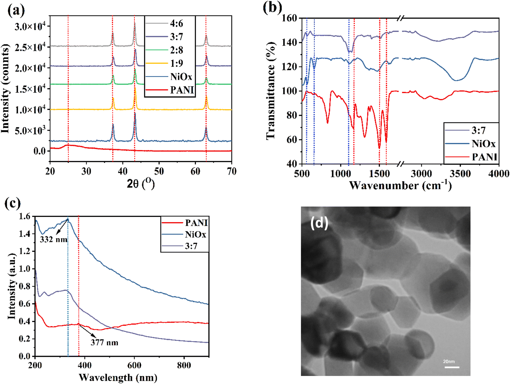
Fig. 1a depicts the XRD patterns of PANI, NiOx nanoparticles, and NiOx/PANI (3![[thin space (1/6-em)]](https://www.rsc.org/images/entities/char_2009.gif) :7 mass/mass). In the range of 2θ from 20 to 70°, PANI exhibits a broad peak at 25.2°, corresponding to the (322) lattice plane.22 NiOx nanoparticles with a cubic structure show diffraction peaks at 37.40° (111), 43.44° (200), and 63.01° (220).23 In Fig. S1 and S2,† the XRD patterns of the NiOx/PANI [1:9 (mass/mass)] suggest that the intensity of the peaks of nickel nanoparticles is intense, while the peaks of PANI are seen with very low intensity in the composite. The characteristic peaks of NiOx shift to higher angles in the XRD pattern of the NiOx/PANI (3:7) due to the interaction of PANI chains and NiOx nanoparticles. Fig. 1b depicts the FTIR spectra of PANI, NiOx, and NiOx/PANI (3:7) materials.
:7 mass/mass). In the range of 2θ from 20 to 70°, PANI exhibits a broad peak at 25.2°, corresponding to the (322) lattice plane.22 NiOx nanoparticles with a cubic structure show diffraction peaks at 37.40° (111), 43.44° (200), and 63.01° (220).23 In Fig. S1 and S2,† the XRD patterns of the NiOx/PANI [1:9 (mass/mass)] suggest that the intensity of the peaks of nickel nanoparticles is intense, while the peaks of PANI are seen with very low intensity in the composite. The characteristic peaks of NiOx shift to higher angles in the XRD pattern of the NiOx/PANI (3:7) due to the interaction of PANI chains and NiOx nanoparticles. Fig. 1b depicts the FTIR spectra of PANI, NiOx, and NiOx/PANI (3:7) materials.
 | ||
| Fig. 1 (a) XRD patterns of different materials. (b) FTIR spectra and (c) UV-Vis spectra of PANI, NiOx, and NiOx/PANI (3:7) materials. (d) TEM image of NiOx nanoparticles. | ||
In the FTIR spectra of NiOx, the main characteristic peaks were found at 564, 656, and 1110 cm−1, assigned to the vibration mode of the Ni–O band.33 The strong peaks observed in the range of 1100–1600 cm−1 in the FTIR spectra of PANI can be correlated to the quinonoid and benzenoid vibrational bands. Specifically, the main peaks at 1584 cm−1 and 1497 cm−1 correspond to the C![[double bond, length as m-dash]](https://www.rsc.org/images/entities/char_e001.gif) N and CC stretching vibration modes, respectively. Additionally, the peaks around 1170 cm−1 are linked to the C–N benzenoid ring stretching mode.34–36 When comparing the FTIR spectra of NiOx/PANI materials to those of PANI and NiOx individually, some noticeable changes can be observed. Firstly, there is a small shift in the wavenumber of the peaks, indicating a modification in the molecular structure. Secondly, the intensity of the peaks also changes, suggesting alterations in the bonding environment. For the nanocomposites NiOx/PANI, the peaks detected at 1620 cm−1 and 1520 cm−1 can be attributed to the CN and CC vibration modes of for various weight ratios of the nanocomposites, indicating the presence of both quinonoid and benzenoid units. Furthermore, the peak around 1147 cm−1 is associated with the C–N stretching mode of the benzenoid ring.37,38 An interesting observation is the appearance of bands at 573 and 1106 cm−1, which can be attributed to the presence of NiOx in the nanocomposite. This indicates a strong interaction between the PANI molecules and the NiOx NPs. Hence, it can be concluded that there are significant reactions between NiOx and PANI materials, leading to the formation of NiOx/PANI within the PANI matrix. Fig. 1c shows the absorbance spectra of PANI, NiOx, and NiOx/PANI. As shown, the PANI sample has a characteristic peak at 377 nm and the NiOx sample has a peak at 332 nm. In the absorbance spectra of NiOx/PANI material, a peak around 332 nm with a slight blue shift is observable, and a shoulder peak around 377 nm, which affirms the successful formation of NiOx/PANI. The TEM images of NiOx nanoparticles are shown in Fig. 1d. The morphology of NiOx nanoparticles is spherical, with an approximate diameter of about 40 nm.
N and CC stretching vibration modes, respectively. Additionally, the peaks around 1170 cm−1 are linked to the C–N benzenoid ring stretching mode.34–36 When comparing the FTIR spectra of NiOx/PANI materials to those of PANI and NiOx individually, some noticeable changes can be observed. Firstly, there is a small shift in the wavenumber of the peaks, indicating a modification in the molecular structure. Secondly, the intensity of the peaks also changes, suggesting alterations in the bonding environment. For the nanocomposites NiOx/PANI, the peaks detected at 1620 cm−1 and 1520 cm−1 can be attributed to the CN and CC vibration modes of for various weight ratios of the nanocomposites, indicating the presence of both quinonoid and benzenoid units. Furthermore, the peak around 1147 cm−1 is associated with the C–N stretching mode of the benzenoid ring.37,38 An interesting observation is the appearance of bands at 573 and 1106 cm−1, which can be attributed to the presence of NiOx in the nanocomposite. This indicates a strong interaction between the PANI molecules and the NiOx NPs. Hence, it can be concluded that there are significant reactions between NiOx and PANI materials, leading to the formation of NiOx/PANI within the PANI matrix. Fig. 1c shows the absorbance spectra of PANI, NiOx, and NiOx/PANI. As shown, the PANI sample has a characteristic peak at 377 nm and the NiOx sample has a peak at 332 nm. In the absorbance spectra of NiOx/PANI material, a peak around 332 nm with a slight blue shift is observable, and a shoulder peak around 377 nm, which affirms the successful formation of NiOx/PANI. The TEM images of NiOx nanoparticles are shown in Fig. 1d. The morphology of NiOx nanoparticles is spherical, with an approximate diameter of about 40 nm.
The morphology of PANI and NiOx/PANI (1:9, 3:7, and 4:6) was investigated using scanning electron microscopy (SEM) and shown in Fig. 2. Fig. 2a illustrates that the PANI nanofiber has a porous morphology, resulting in a larger surface area. The FESEM image of the NiOx/PANI indicates the incorporation of NiOx in the polymer matrix, with an average diameter in the nanometer range, likely due to the π–π and electrovalent interactions between the PANI molecules and NiOx.39,40 EDX-mapping analysis (Fig. 3) confirmed the successful formation of the nanocomposite, with well-distributed C, N, O, and Ni elements. In Fig. S3,† the elemental composition of the NiOx/PANI materials was also studied by EDX, with no trace of impurities observed. Fig. 4a–c show the synthesis of PANI NPs, NiOx–PANI, and NiOx NPs respectively. Complete details of device fabrication is given in ESI.†
 | ||
| Fig. 2 FESEM image of (a) PANI, (b) 1:9, (c) 3:7, and (d) 4:6 NiOx/PANI. | ||
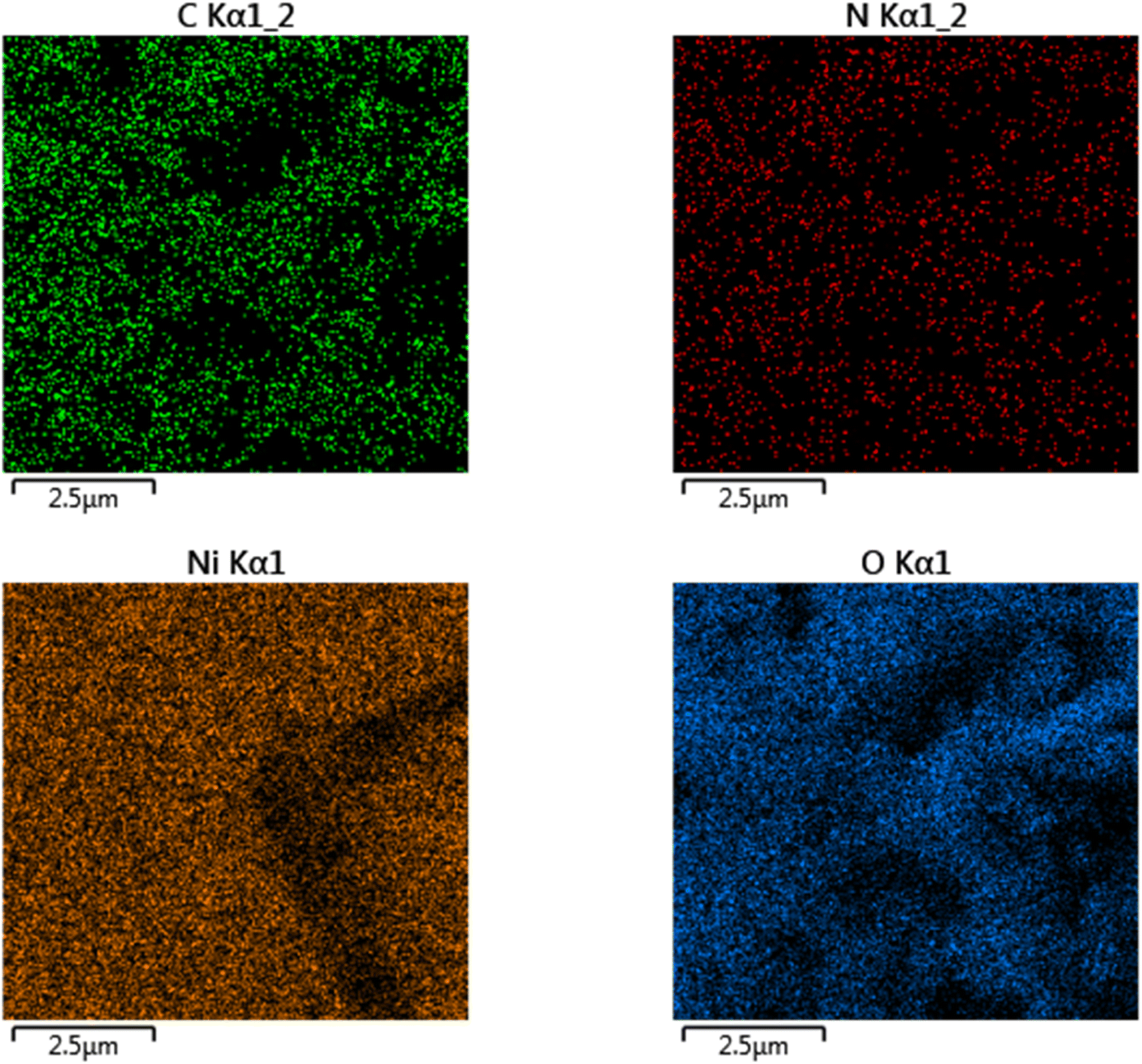 | ||
| Fig. 3 Mapping FESEM to show elements distribution of C, N, Ni, and O on the NiOx/PANI nanocomposite. | ||
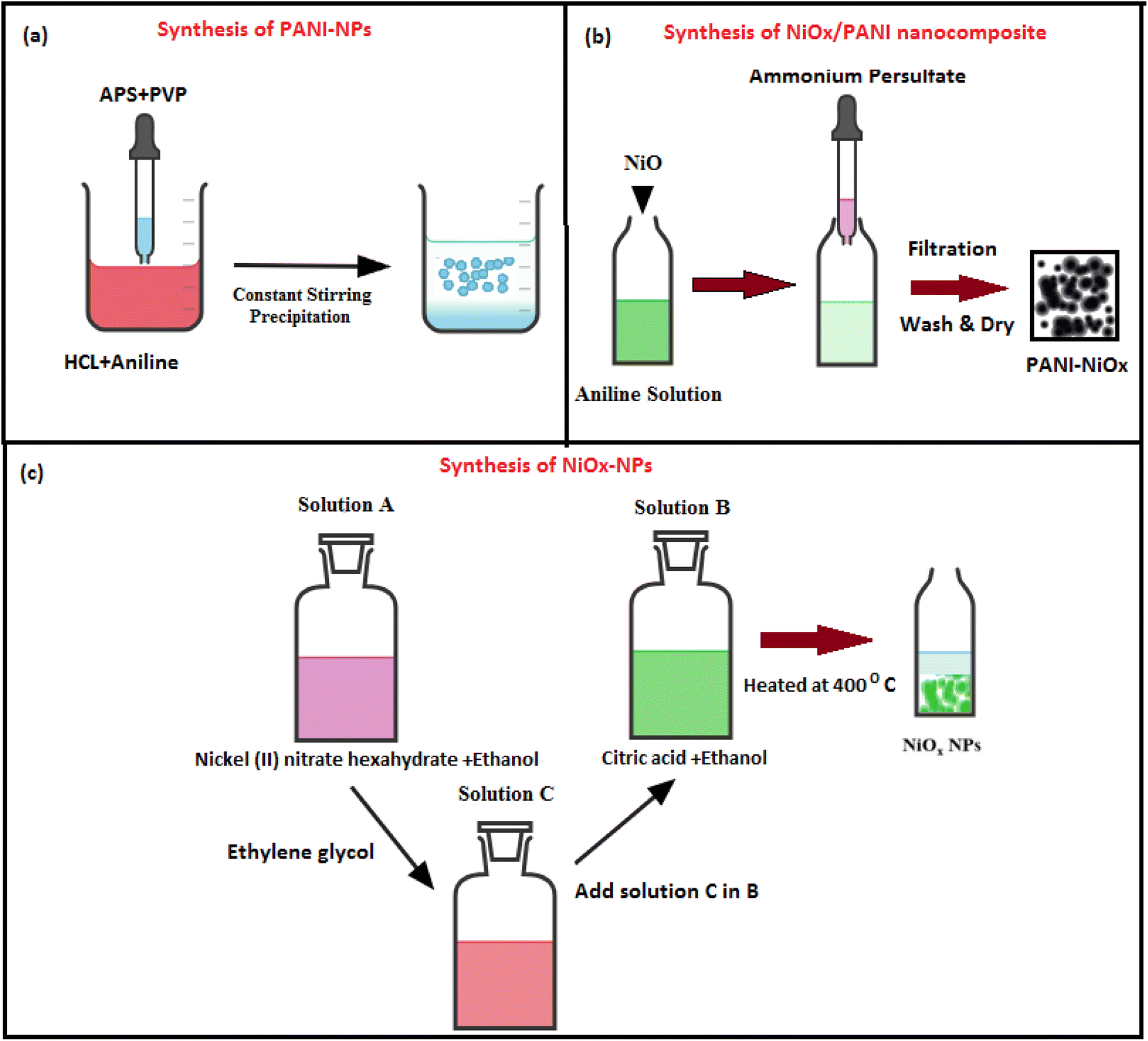 | ||
| Fig. 4 Synthesis of (a) PANI-NPs (b) NiOx/PANI nanocomposite and (c) NiOx NPs. | ||
The devices were also assembled with the following configuration: FTO/TiO2/FAPbI3 perovskite/HTM doped carbon. J–V measurements were used to evaluate the performance of PSCs under AM 1.5G irradiance (Fig. 5a). Based on the J–V curves, the photovoltaic parameters of the devices, including FF, open-circuit voltage (VOC), short circuit current density (JSC), and PCE, were calculated and are given in Table S1.† In general, the addition of NiOx/PANI as a HTM to carbon paste improves JSC, VOC, and FF parameters and raises device PCE. In which the device exhibited an improved PCE of 17.52%, along with a VOC of 1.114 V, a JSC of 23.00 mA cm−2, and an FF of 68.39. Notably, the PCE was further enhanced to 18.30% when NiOx/PANI was doped within the carbon electrode.
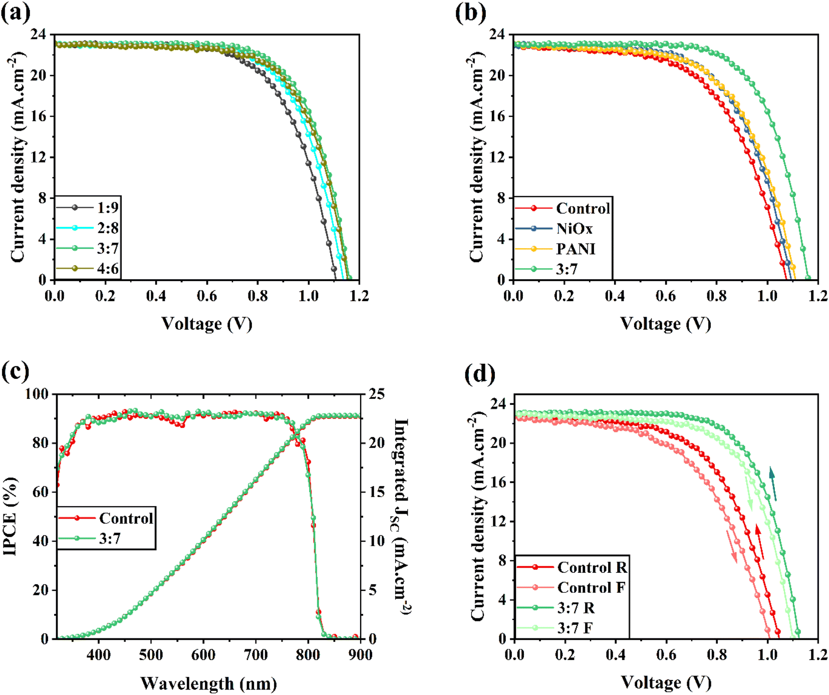 | ||
| Fig. 5 J–V curves of different HTL-free CPSCs with carbon electrodes contained different NiOx/PANI nanocomposites. (b) J–V curves of devices with pure carbon electrode (control), carbon electrodes contained NiOx, PANI, and NiOx/PANI (3:7). (c) IPCE curves of control and 3:7 carbon electrode-based devices. (d) J–V curves of control and 3:7 devices in forward and reverse directions. | ||
To determine the ideal weight ratio and study the effects of different NiOx/PANI weight ratios on photovoltaic performance, different perovskite solar cell amounts were made, and their J–V characteristics were assessed. The J–V curves of the best devices with various NiOx/PANI in carbon are displayed in Fig. 5a. Interestingly, mixing carbon paste with NiOx/PANI (3:7) yields the best results. Fig. 5b shows the J–V curve for the best-performing device under AM 1.5G illumination without HTM (control), NiOx, and PANI, as well as the device using NiOx/PANI (3:7) as HTM in carbon-based devices. Table S1† lists the associated photovoltaic parameters that were taken from the J–V curve. The device incorporating NiOx/PANI (3:7)+CE HTM exhibits a notable enhancement in VOC and JSC. The integration of NiOx/PANI (3:7)+CE HTM is responsible for the increase in VOC because it shifts the Fermi level of carbon downward.
It is worth mentioning that the inclusion of NiOx+carbon results in inferior device performance, despite having a slightly higher VOC compared to a device without a hole transport material (HTM). The reduced efficiency can be attributed to the limitation in charge transport caused by the inadequate conductivity of NiOx HTM. Conversely, the introduction of NiOx/PANI greatly enhances the transfer of holes from the light-harvesting layer to the carbon electrode.
Fig. 5c displays the incident photon-to-electron conversion efficiency (IPCE) responses and integrated short circuit current density (JSC) for the control cell and perovskite solar cells (PSCs) utilizing NiOx/PANI(3:7)+CE as the hole transport material (HTM) and counter electrode. The results demonstrate that the PSC incorporating NiOx/PANI(3:7)+CE exhibits a distinct IPCE spectrum shape and higher IPCE value within the 350 to 900 nm range compared to devices utilizing pure carbon. Consequently, the integrated JSC values of 22.74 and 22.80 mA cm−2 align with the J–V characteristics of the devices. Fig. 5d illustrates the standard J–V curves of PSCs fabricated with two types of cells: the control cell and PSCs based on NiOx/PANI(3:7)+CE. In both the forward and reverse scan directions, the J–V curves were measured. The hysteresis problem of the current–voltage curve of the HTL-free carbon-based PSCs, in particular, can also be resolved by the NiOx/PANI. The electrical properties of the cells acquired from both the forward scan (FS) and reverse scan (RS) directions are shown in Table 1. Eqn (1) was utilized to evaluate the hysteresis changes and determine the hysteresis index (HI), which represents the degree of hysteresis.
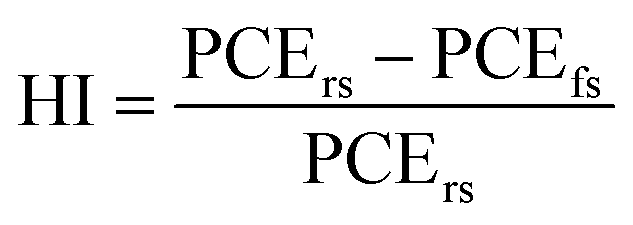 | (1) |
:7 based HTL-free CPSCs in reverse and forward sweeping directions to measure hysteresis index
| Device name | PCE reverse (%) | PCE forward (%) | HI (%) |
|---|---|---|---|
| Control | 14.02 | 12.58 | 10.28 |
| 3:7 |
17.75 | 16.52 | 6.95 |
In the equation, PCErs represents the calculated PCE from the reverse scan, while PCEfs represents the calculated PCE from the forward scan. Larger HI values correspond to increased hysteresis. As depicted in Table 1, the control device exhibits the highest HI value at 10.28%. In contrast, the device incorporating NiOx/PANI showcases a lower HI value of 6.95%. The significant hysteresis observed in the control device is attributed to the poor interface between the light-harvester layer and the carbon electrode, which negatively affects carrier transport through the interface. On the other hand, the NiOx/PANI-based devices demonstrate improved interfacial contacts, resulting in reduced hysteresis and enhanced carrier transport.
In this study, we conducted a comparison of the stability between the device based on NiOx/PANI and the control cell. The intrinsic affinity of FAPbI3 perovskites to reaction with moisture poses a challenge to the stability of PSCs, making it a primary concern. To evaluate the stability, the cells were exposed to ambient air with a relative humidity of 30–40% at room temperature in dark conditions, without encapsulation. Fig. 6a illustrates the stability of the cells over a period of 2400 hours. The PSC incorporating NiOx/PANI+CE maintained 96% of its initial power PCE, while the control device retained 93% of its original performance. Furthermore, Fig. 6b displays the stability of the PSCs under simulated sunlight irradiance at a humidity level of 25–30% and room temperature. The graph indicates that PSCs utilizing the NiOx/PANI exhibit higher stability compared to the control PSCs. This enhanced stability can be attributed to the small porosity of NiOx/PANI+carbon, resulting from the smaller size of the metal oxide on the carbon material and thick NiOx/PANI+CE coating (∼15 μm). The long-term stability performance of the NiOx/PANI-based devices may be attributed to this decreased porosity, which prevents oxygen and moisture from penetrating through the counter electrode.
 | ||
| Fig. 6 Stability tests of control and 3:7-based HTL-free CPSCs against (a) ambient air with relative humidity of 30–40% in dark conditions at room temperature and (b) simulated sunlight irradiance at a humidity level of 25–30% at room temperature. | ||
Next, we use the PSC's capacitance–voltage (C–V) curve to measure the carrier concentration. The Mott–Schottky equation (M–S) is used to calculate the carrier density based on the curve's slope. To determine the built-in potential (Vbi), the linear portion of the Mott–Schottky plot in Fig. 7a was utilized. The Vbi of the NiO/PANI device was higher than that of the control device. This indicates that a high VOC is produced by the NiOx/PANI's ability to increase charge separation and decrease carrier rearward movement at the carbon–perovskite interface.41 Fig. 7b presents the impedance spectroscopy spectra obtained from various cells: the control cell, PSCs based on NiO+CE, PAN+CE, and NiOx/PANI(3:7)+CE. The measurements were performed under dark conditions at open-circuit voltage. The inset of Fig. 5b showcases the equivalent circuit diagram that was utilized to fit the EIS curves. The charge recombination resistance (Rrec) in the low-frequency region exhibited a negative correlation with the degree of charge recombination. Notably, the NiOx/PANI+CE cell displayed a significantly higher Rrec value (1687 Ω) in comparison to the NiO+CE cell (897 Ω), the PANI+CE cell (954 Ω), and the control cell (784 Ω). This indicates that the addition of NiOx/PANI effectively suppressed charge carrier accumulation at the interfaces and reduced charge carrier recombination. These findings align with the results obtained from photoluminescence (PL) measurements. A device was fabricated with a different carbon electrode architecture in order to study the vertical charge transport properties. As expected, the I–V curve of the device containing a NiOx/PANI+CE showed an enhanced slope when compared to the control devices NiOx+CE and PANI+carbon electrode, as shown in Fig. 7c. The improved conductivity observed in the NiO/PANI+CE device can be attributed to its enhanced ability to extract holes from the perovskite film. This increase in conductivity aligns with the superior performance of the perovskite solar cells (PSCs), as demonstrated by the higher JSC and FF.42 Furthermore, the linear relationship observed in the J–V curves indicates the presence of good ohmic contacts in all device configurations.43,44
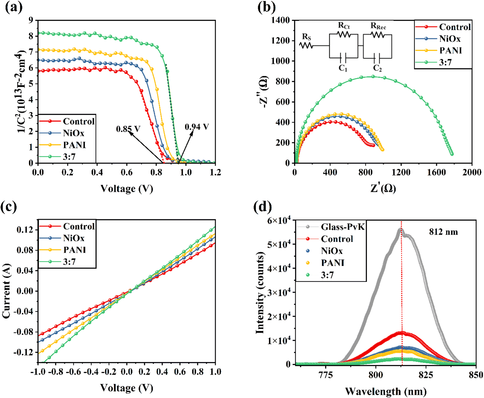 | ||
| Fig. 7 (a) Mote–Schottky and (b) Nyquist plots of HTL-free CPSCs fabricated based on different carbon electrodes. Inset of Fig. 5b shows the equivalent circuit diagram used to fit EIS curves. (c) Dark I–V of different carbon electrodes. (d) PL response of FTO/ETL/FAPbI3/different carbon electrodes. | ||
To further validate the improved charge transport properties resulting from the integration of NiO/PANI into the carbon electrode (CE), Fig. 7d presents the steady-state photoluminescence (PL) spectra. The spectra compare a perovskite absorber film deposited on a glass/fluorine-doped tin oxide (FTO) substrate without any additional layers, with the structures FTO/ETL/FAPbI3/using different carbon electrodes. In the absence of additional layers, the bare perovskite film exhibited a distinct photoluminescence (PL) peak at 812 nm. The steady-state PL spectra provide clear evidence that the NiOx/PANI+CE configuration effectively suppresses the PL intensity, suggesting enhanced charge transfer from the light-harvesting layer.45,46 This confirms that the addition of NiOx/PANI enhances the charge transport properties of the device.
To examine the band alignment between the NiOx/PANI+CE material and the perovskite absorber layer, ultraviolet photoelectron spectroscopy (UPS) test were measured. Fig. 8a displays the UPS spectra for pure carbon and NiOx/PANI+CE. The results indicate that the incorporation of NiOx/PANI has a minimal effect on the band positions. There is a shift of 0.66 eV in the work function (WF). The energy level at −5.39 eV for NiOx/PANI+CE corresponds to an intermediate and favorable position, which facilitates efficient hole transfer from perovskite to the NiOx/PANI+CE (Fig. 8b).
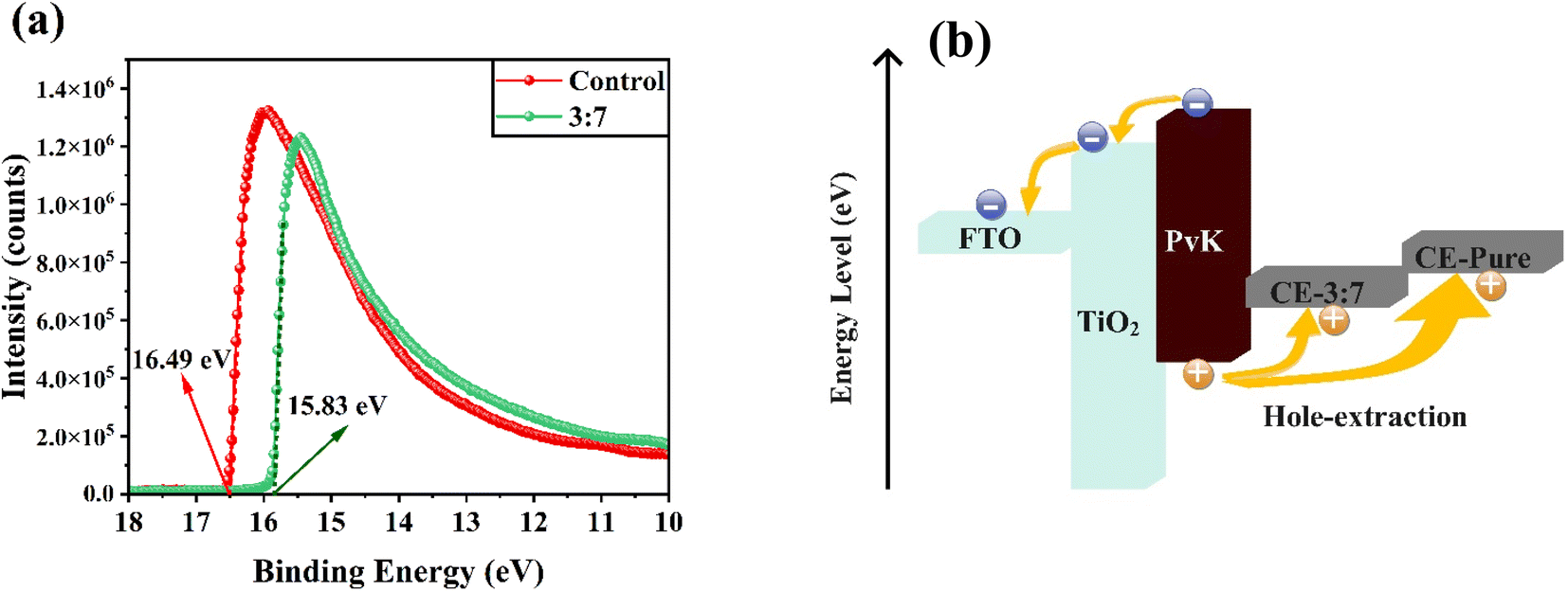 | ||
| Fig. 8 (a) UPS spectra of control and 3:7 NiOx/PANI-contained carbon electrodes. (b) Energy band diagram of each component in the fabricated HTL-free CPSCs with control and 3:7 NiOx/PANI-contained carbon electrodes, showing the separation and transport of photo-generated carriers. | ||
3. Conclusion
In our research, we implemented a doping technique that involved incorporating a NiOx/PANI into the carbon electrode to increase the photovoltaic properties of PSCs. The introduction of this nanocomposite resulted in a beneficial energy band alignment with both the perovskite and carbon materials, leading to decreased resistance and improved conductivity. The unique structure of the nanocomposite provided a larger specific surface area compared to regular carbon, further facilitating the reduction of resistance and improvement of conductivity. Furthermore, the inclusion of the nanocomposite facilitated enhanced interface contact between the carbon electrode and the perovskite layer, resulting in reduced defect generation. The primary objective of incorporating the nanocomposite was to improve charge transfer, energy level alignment, and interface contact while also mitigating surface degradation of the perovskite. These combined effects effectively reduced charge recombination and minimized energy loss in the system. As a result, the overall efficiency increased to 18.30%, which is 26.5% higher than that of devices using a pure carbon electrode. Additionally, the NiO/PANI+CE-based PSCs exhibited an encouraging 96% of initial power conversion efficiency (PCE) after 2400 hours in an ambient atmosphere. The successful utilization of NiO/PANI+CE as the hole transport material and carbon electrode significantly contributed to the stability test's positive outcome.Conflicts of interest
The authors declare no conflict of interest.Acknowledgements
The authors present their appreciation to King Saud University for funding this research through Researchers Supporting Program number (RSPD2024R990), King Saud University, Riyadh, Saudi Arabia.References
- J. Rajavedhanayagam, V. Murugadoss, D. K. Maurya and S. Angaiah, Cu2NiSnS4/graphene nanohybrid as a newer counter electrode to boost-up the photoconversion efficiency of dye sensitized solar cell, ES Energy Environ., 2022, 18, 65–74 CAS.
- Y. Ma, Y. Zhang, M. Liu, T. Han, Y. Wang and X. Wang, Improving the performance of quantum dot sensitized solar cells by employing Zn doped CuInS2 quantum dots, Adv. Compos. Hybrid Mater., 2022, 1–8 Search PubMed.
- V. Murugadoss, D. Y. Kang, W. J. Lee, I. G. Jang and T. Geun Kim, Fluorine-induced surface modification to obtain stable and low energy loss zinc oxide/perovskite interface for photovoltaic application, Adv. Compos. Hybrid Mater., 2022, 5, 1385–1395 CrossRef CAS.
- B. He, Y. Xu, J. Zhu and X. Zhang, Effects of the doping density of charge-transporting layers on regular and inverted perovskite solar cells: numerical simulations, Adv. Compos. Hybrid Mater., 2021, 4, 1146–1154 CrossRef CAS.
- J. Kaur, H. D. Shelke, H. M. Pathan and R. Kumar, Optimization of photovoltaic characteristics of CIGS/Si heterojunction solar cells, ES Energy Environ., 2022, 17, 56–63 CAS.
- H. Gao, J. Li, Y. Liu and J. Leng, Shape memory polymer solar cells with active deformation, Adv. Compos. Hybrid Mater., 2021, 4, 957–965 CrossRef CAS.
- M. K. Mohammed, M. I. Abualsayed, A. M. Alshehri, A. Kumar, M. Dehghanipour, R. S. Alnayli, S. Aftab and E. Akman, Synergistic Effects of Energy Level Alignment and Trap Passivation via 3,4-Dihydroxyphenethylamine Hydrochloride for Efficient and Air-Stable Perovskite Solar Cells, ACS Appl. Energy Mater., 2024, 7(3), 1358–1368 CrossRef CAS.
- J. Jeong, M. Kim, J. Seo, H. Lu, P. Ahlawat, A. Mishra, Y. Yang, M. A. Hope, F. T. Eickemeyer and M. Kim, Pseudo-halide anion engineering for α-FAPbI3 perovskite solar cells, Nature, 2021, 592, 381–385 CrossRef CAS PubMed.
- Y. Xu, Y. Tian, M. Hou, Y. Wu, Y. Ding, Y. Zhao, X. Zhang and G. Hou, Performance promotion through dual-interface engineering of CuSCN layers in planar perovskite solar cells, J. Phys. Chem. C, 2020, 124, 27977–27984 CrossRef CAS.
- X. Xu, Z. Liu, Z. Zuo, M. Zhang, Z. Zhao, Y. Shen, H. Zhou, Q. Chen, Y. Yang and M. Wang, Hole selective NiO contact for efficient perovskite solar cells with carbon electrode, Nano Lett., 2015, 15, 2402–2408 CrossRef CAS PubMed.
- F. Arjmand, S. J. Fatemi, S. Maghsoudi and A. Naeimi, The first and cost effective nano-biocomposite, zinc porphyrin/CuO/reduced graphene oxide, based on Calotropis procera plant for perovskite solar cell as hole-transport layer under ambient conditions, J. Mater. Res. Technol., 2022, 16, 1008–1020 CrossRef CAS.
- X. Ding, C. Chen, L. Tao, C. Wu, M. Zheng, H. Lu, H. Xu, H. Li and M. Cheng, Dopant-free methoxy substituted copper(II) phthalocyanine for highly efficient and stable perovskite solar cells, Chem. Eng. J., 2020, 387, 124130 CrossRef CAS.
- S. Sajid, A. M. Elseman, H. Huang, J. Ji, S. Dou, H. Jiang, X. Liu, D. Wei, P. Cui and M. Li, Breakthroughs in NiOx-HTMs towards stable, low-cost and efficient perovskite solar cells, Nano Energy, 2018, 51, 408–424 CrossRef CAS.
- Q. Jiang, X. Sheng, B. Shi, X. Feng and T. Xu, Nickel-cathoded perovskite solar cells, J. Phys. Chem. C, 2014, 118, 25878–25883 CrossRef CAS.
- L. Etgar, P. Gao, Z. Xue, Q. Peng, A. K. Chandiran, B. Liu, M. K. Nazeeruddin and M. Grätzel, Mesoscopic CH3NH3PbI3/TiO2 heterojunction solar cells, J. Am. Chem. Soc., 2012, 134, 17396–17399 CrossRef CAS PubMed.
- J. Shi, J. Dong, S. Lv, Y. Xu, L. Zhu, J. Xiao, X. Xu, H. Wu, D. Li and Y. Luo, Hole-conductor-free perovskite organic lead iodide heterojunction thin-film solar cells: high efficiency and junction property, Appl. Phys. Lett., 2014, 104, 063901 CrossRef.
- S. Liu, K. Cao, H. Li, J. Song, J. Han, Y. Shen and M. Wang, Full printable perovskite solar cells based on mesoscopic TiO2/Al2O3/NiO (carbon nanotubes) architecture, Sol. Energy, 2017, 144, 158–165 CrossRef CAS.
- S. Sajid, A. M. Elseman, J. Ji, S. Dou, D. Wei, H. Huang, P. Cui, W. Xi, L. Chu and Y. Li, Computational study of ternary devices: stable, low-cost, and efficient planar perovskite solar cells, Nano-Micro Lett., 2018, 10, 1–11 CrossRef PubMed.
- L. Chu, W. Liu, Z. Qin, R. Zhang, R. Hu, J. Yang, J. Yang and X. a. Li, Boosting efficiency of hole conductor-free perovskite solar cells by incorporating p-type NiO nanoparticles into carbon electrodes, Sol. Energy Mater. Sol. Cells, 2018, 178, 164–169 CrossRef CAS.
- L. Cheng, Y. Ji, X. Liu, L. Mu and J. Zhu, Sorption mechanism of organic dyes on a novel self-nitrogen-doped porous graphite biochar: coupling DFT calculations with experiments, Chem. Eng. Sci., 2021, 242, 116739 CrossRef CAS.
- J. Zhao, H. Lai, Z. Lyu, Y. Jiang, K. Xie, X. Wang, Q. Wu, L. Yang, Z. Jin and Y. Ma, Hydrophilic Hierarchical Nitrogen-Doped Carbon Nanocages for Ultrahigh Supercapacitive Performance, Adv. Mater., 2015, 27, 3541–3545 CrossRef CAS PubMed.
- H. Chen and S. Yang, Methods and strategies for achieving high-performance carbon-based perovskite solar cells without hole transport materials, J. Mater. Chem. A, 2019, 7, 15476–15490 RSC.
- Y. Du, X. Zhang, Y. Shi, X. Hou, F. Li, Q. Zhang, Q. Tai, P. Liu and X.-Z. Zhao, Optimized crystallization and defect passivation with yttrium(III) doped MAPbBr3 film for highly efficient and stable hole-transport-layer-free carbon-based perovskite solar cells, J. Alloys Compd., 2022, 890, 161909 CrossRef CAS.
- Z. Zhang, F. Qiu, T. Shen, L. Xu, J. Ma and J. Qi, Co/Eu co-doped electron transport layer enhances charge extraction and light absorption for efficient carbon-based HTM-free perovskite solar cells, Int. J. Energy Res., 2021, 45, 5224–5234 CrossRef CAS.
- L. Lin, P. Li, L. Jiang, Z. Kang, Q. Yan, H. Xiong, S. Lien, P. Zhang and Y. Qiu, Boosting efficiency up to 25% for HTL-free carbon-based perovskite solar cells by gradient doping using SCAPS simulation, Sol. Energy, 2021, 215, 328–334 CrossRef CAS.
- M. Shojaeifar and E. Mohajerani, The effect of temperature on electric field assisted sintering in dye-sensitized solar cells, J. Mater. Sci., 2019, 54, 1629–1639 CrossRef CAS.
- M. Shojaeifar, E. Mohajerani and M. Fathollahi, Electric field assisted sintering to improve the performance of nanostructured dye sensitized solar cell (DSSC), J. Appl. Phys., 2018, 123, 013102 CrossRef.
- M. Shojaeifar, M. Asemi, E. Mohajerani and M. Ghanaatshoar, Electro-optical enhancement of nonporous Zn2SnO4-based dye-sensitized solar cell by electric field assisted sintering, Current Applied Physics, 2020, 20, 358–362 CrossRef.
- S. Mashhoun, Y. Hou, H. Chen, F. Tajabadi, N. Taghavinia, H. J. Egelhaaf and C. J. Brabec, Resolving a critical instability in perovskite solar cells by designing a scalable and printable carbon based electrode-interface architecture, Adv. Energy Mater., 2018, 8, 1802085 CrossRef.
- S. Sajid, A. M. Elseman, D. Wei, J. Ji, S. Dou, H. Huang, P. Cui and M. Li, NiO@carbon spheres: a promising composite electrode for scalable fabrication of planar perovskite solar cells at low cost, Nano Energy, 2019, 55, 470–476 CrossRef CAS.
- K. Ramachandran, C. Jeganathan and S. Karuppuchamy, Electrodeposition of nanostructured bilayer CuI@CuSCN as hole transport material for highly efficient inverted perovskite solar cells, J. Alloys Compd., 2021, 881, 160530 CrossRef CAS.
- N. Rajamanickam, S. Kumari, V. K. Vendra, B. W. Lavery, J. Spurgeon, T. Druffel and M. K. Sunkara, Stable and durable CH3NH3PbI3 perovskite solar cells at ambient conditions, Nanotechnology, 2016, 27, 235404 CrossRef PubMed.
- X. Chen, F. Zhang, Z. Yang and S. Huang, One-pot hydrothermal synthesis of reduced graphene oxide/carbon nanotube/α-Ni(OH)2 composites for high performance electrochemical supercapacitor, J. Power Sources, 2013, 243, 555–561 CrossRef CAS.
- M. Afzali, Z. Jahromi and R. Nekooie, Sensitive voltammetric method for the determination of naproxen at the surface of carbon nanofiber/gold/polyaniline nanocomposite modified carbon ionic liquid electrode, Microchem. J., 2019, 145, 373–379 CrossRef CAS.
- S. Ashokkumar, H. Vijeth, L. Yesappa, M. Vandana and H. Devendrappa, Lower optical band gap and morphology of electrochemically synthesized polyaniline/CuO nanocomposites, AIP Conf. Proc., 2019, 030059 CrossRef.
- M. Ayad, G. El-Hefnawy and S. Zaghlol, Facile synthesis of polyaniline nanoparticles; its adsorption behavior, Chem. Eng. J., 2013, 217, 460–465 CrossRef CAS.
- F. Arjmand, Z. Golshani, S. Maghsoudi, A. Naeimi and S. J. Fatemi, SnO2@ZnO nanocomposites doped polyaniline polymer for high performance of HTM-free perovskite solar cells and carbon-based, Sci. Rep., 2022, 12, 21188 CrossRef CAS PubMed.
- Z. Golshani, S. Maghsoudi and S. M. A. Hosseini, Enhancement of the photovoltaic performance of HTL-free-perovskite solar cells based on carbon electrode via the modification of electron transport layer with copper oxide@polyaniline nanocomposite, Energy Rep., 2022, 8, 13596–13609 CrossRef.
- A. S. Adekunle and K. I. Ozoemena, Electron transport and electrocatalytic properties of MWCNT/nickel nanocomposites: hydrazine and diethylaminoethanethiol as analytical probes, J. Electroanal. Chem., 2010, 645, 41–49 CrossRef CAS.
- X. Xia, J. Tu, J. Zhang, X. Wang, W. Zhang and H. Huang, A highly porous NiO/polyaniline composite film prepared by combining chemical bath deposition and electro-polymerization and its electrochromic performance, Nanotechnology, 2008, 19, 465701 CrossRef CAS PubMed.
- G. Yang, C. Wang, H. Lei, X. Zheng, P. Qin, L. Xiong, X. Zhao, Y. Yan and G. Fang, Interface engineering in planar perovskite solar cells: energy level alignment, perovskite morphology control and high performance achievement, J. Mater. Chem. A, 2017, 5, 1658–1666 RSC.
- A. M. Naji, S. H. Kareem, A. H. Faris and M. K. Mohammed, Polyaniline polymer-modified ZnO electron transport material for high-performance planar perovskite solar cells, Ceram. Int., 2021, 47, 33390–33397 CrossRef CAS.
- M. M. Rashad, A. M. Elseman and A. M. Hassan, Facile synthesis, characterization and structural evolution of nanorods single-crystalline (C4H9NH3) 2PbI2X2 mixed halide organometal perovskite for solar cell application, Optik, 2016, 127, 9775–9787 CrossRef CAS.
- A. Elseman, A. Shalan, M. Rashad and A. Hassan, Experimental and simulation study for impact of different halides on the performance of planar perovskite solar cells, Mater. Sci. Semicond. Process., 2017, 66, 176–185 CrossRef CAS.
- M. Dehghanipour, A. Behjat and H. A. Bioki, Fabrication of stable and efficient 2D/3D perovskite solar cells through post-treatment with TBABF4, J. Mater. Chem. C, 2021, 9, 957–966 RSC.
- H. Mohseni, M. Dehghanipour, N. Dehghan, F. Tamaddon, M. Ahmadi, M. Sabet and A. Behjat, Enhancement of the photovoltaic performance and the stability of perovskite solar cells via the modification of electron transport layers with reduced graphene oxide/polyaniline composite, Sol. Energy, 2021, 213, 59–66 CrossRef CAS.
Footnote |
| † Electronic supplementary information (ESI) available. See DOI: https://doi.org/10.1039/d4ra01287a |
| This journal is © The Royal Society of Chemistry 2024 |