
 Open Access Article
 This Open Access Article is licensed under a Creative Commons Attribution-Non Commercial 3.0 Unported Licence
Synthesis of a high-iron fly-ash-based Na-X molecular sieve and its application in the adsorption of low concentration of CO2
Jiaxing Guoa,
Hong Wu *b,
Yao Weia,
Yingju Miaob,
Jingyuan Qua and
Ping Wangb
*b,
Yao Weia,
Yingju Miaob,
Jingyuan Qua and
Ping Wangb
aCollege of Environmental and Chemical Engineering, Dalian University, Dalian, Liaoning, China
bCollege of Chemical and Materials Engineering, Liupanshui Normal University, Liupanshui, Guizhou, China
First published on 5th January 2024
Abstract
In addressing the environmental challenges posed by the accumulation of fly ash (FA), efforts have been geared towards its high-value utilization. By the use of high-iron FA as a raw material, a high-iron fly-ash-based Na-X molecular sieve was successfully synthesized by hydrothermal method. We combined pretreatment methods such as high-temperature calcination, acid leaching and alkali fusion activation. The as-synthesized product was used for the adsorption of a low concentration of CO2, and the adsorption data were fitted by a physical model. The changes in iron content in pretreatment and molecular sieve synthesis were revealed by SEM-mapping, UV-Raman and UV-Vis. The results showed that the pretreatment process reduces the iron content from 32.3% to 13.3%, and converts the inactive phases to active phases, with n (SiO2/Al2O3) = 4.94. The activated product was transformed further to a Na-X molecular sieve using a hydrothermal method. The product has a single crystal phase and octahedral crystal structure. Its specific surface area was 646.634 m2 g−1, and micropores were distributed between 0.46 nm and 0.71 nm, with a mesoporous phase of 4.6 nm. When used to adsorb a low concentration of CO2, the Na-X molecular sieve has a high adsorption capacity of 3.70 mmol g−1, which reaches 95.11% that of the commercial Na-X molecular sieve. The adsorption breakthrough time and adsorption capacity decreased with an increase in temperature. The adsorption kinetics were consistent with the Bangham model for surface pore adsorption and Weber–Morris model for internal diffusion. During the synthesis process, iron was converted from highly dispersed iron oxide to four-coordinated framework iron. Thus, this paper paves a path for the high-quality transformation and utilization of high-iron fly-ash.
Introduction
Fly ash, as a primary solid waste product of coal-fired power plants, constitutes a significant environmental concern. The substantial volume of unutilized fly ash encroaches on land resources and contributes to pollution due to the presence of solid fine particles and heavy metals. These pollutants adversely affect the surrounding air and water quality, posing risks to human health.1 Currently, the utilization of fly ash is predominantly in low-value-added applications such as construction and agriculture. A pivotal challenge and focal point of contemporary research is harnessing strategies for the high-value application of this waste material. Notably, the chemical composition of fly ash, rich in Si and Al, aligns with that of zeolite. Zeolite is synthesized from fly ash. Zeolite, a silicate aluminate mineral, is characterized by a skeleton structure formed by TO4 tetrahedra (T = Si/Al) interconnected through shared oxygen atoms. This unique structural configuration endows zeolites with broad application prospects in the fields of wastewater treatment, waste gas adsorption and industrial catalysis. The increasing demand for zeolites amplifies the significance of synthesizing them from fly ash. This strategy addresses the environmental issues associated with fly ash disposal, but also curtails the costs of zeolite synthesis. This approach epitomizes a high-value, eco-efficient solution aligning with the paradigm “treatment of waste with another waste”.2Fu et al. examined the pretreatment of fly ash, with an emphasis on optimizing parameters including fineness, roasting, acid leaching, alkali fusion activation and impurity removal to prepare fly ash that was suited for the molecular sieve synthesis.3 Wu et al. employed hydrochloric acid to eliminate calcium and iron impurities from fly ash, aiming to minimize Al2O3 loss and ensure the purity of the synthesized molecular sieve.4” Quero et al. explored the comparative efficacy of NaOH and KOH in the hydrothermal synthesis of fly-ash-based zeolite, establishing superior activation performance of NaOH.5 Hui et al. achieved the synthesis of a high-quality 4 A zeolite through precise temperature control during a hydrothermal reaction.6 Chen et al. expounded the method and process for synthesizing a Na-X molecular sieve from fly ash, covering its composition, alkali calcination, reaction ratio and crystallization parameters, thereby laying a foundation framework for future research.7 Wang et al. utilized fly ash as a raw material to produce a Cu-SSZ-13 molecular sieve for NH3-SCR catalysts to achieve the same denitrification activity as that of a commercial zeolite.8 Jin et al. employed fly ash to fabricate a CHA molecular sieve, which was applied in selective reduction catalysts.9 He et al. reported the synthesis of a molecular sieve from fly ash, boasting a Ni2+ removal rate of 94% in wastewater treatment.10 Cardoso et al. applied fly-ash-based Na–P1 molecular sieve for wastewater treatment, exhibiting increased removal rates for As5+, Ni+, Ca2+, and Cu2+.11 Ren crafted a Y molecular sieve from fly ash for acetone adsorption, studied its mechanism, and introduced “biomass ash doping” and “tempering fly ash,” resulting in a ZSM-5 zeolite with adjustable Si/Al contents.12 The research extended to evaluate the adsorption performance of these zeolites to VOCs, uncovering the adsorption mechanism of a ZSM-5 zeolite. Mee et al. synthesized Na-P1 and Na-A zeolites from fly ash and introduced alkali and alkaline-earth metal cations via ion exchange, enhancing low-concentration CO2 adsorption, with calcium ions exhibiting optimal performance due to their electrostatic and acid–base interactions.13 Panek et al. prepared the MCM-41 molecular sieve from fly ash, which, if impregnated with PEI, displayed a CO2 adsorption capacity surpassing that of commercial zeolites.14 Margarita et al. leveraged fly ash for the synthesis of a Na-X molecular sieve for CO2 adsorption, whereby iron from fly ash was transformed to Fe2+ or Fe3+, enhancing the adsorption capacity.15,16 Boycheva et al. affirmed that fly-ash-based Na-X molecular sieve is effective for CO2 adsorption.17 Iron oxide in fly ash proved beneficial for CO2 adsorption and molecular-sieve crystal growth, or integrating into the cage or pore of the molecular sieve as nanoparticles. Ren et al. used fly ash as a raw material to synthesize a Y-type molecular sieve by an alkali fusion hydrothermal method for acetone adsorption. The results showed that Langmuir and Bangham models could better describe the experimental data; it was concluded that internal diffusion was the main resistance to mass transfer.57 Yu et al. compared the adsorption behaviour of CBZ on two types of nanoporous carbons derived from two types of Zn-MOFs. They showed that the graphitization defects of MOFs-derived nanoporous carbon could effectively improve the adsorption performance of the adsorbent. The results showed that the adsorption process of CBZ on nanoporous carbon included rapid adsorption on the surface of the adsorbent and slow diffusion within the adsorbent.58 Through the alkali fusion activation of fly ash after high-temperature calcination and acid leaching, metal oxides in the fly ash are partially dissolved and reactions occur with the existing aluminosilicate, facilitating zeolite molecular sieve synthesis with adsorption capacity surpassing traditional counterparts.18–20
Using the Si and Al of FA, various configurations of molecular sieves can be successfully synthesized, good results have been obtained in the fields of adsorption and catalysis. However, some problems still persist: (1) due to the high content and complex form of iron in FA, it cannot be completely removed by pretreatment. Few studies have focused on whether the remaining iron in the pretreated FA can enter the skeleton structure of the molecular sieve. (2) At present, the methods for synthesizing molecular sieves from iron-containing FA after pretreated is mainly assisted by microwave, ultrasonic and other technologies. Few studies have focused on how to use simple and efficient methods to synthesize molecular sieves. (3) Studies on the adsorption effect of a high-iron fly-ash-based molecular sieve on the adsorption of low concentration of CO2 are scarce. (4) The materials used for absorbing CO2 are mainly mesoporous silica and ordered mesoporous carbon. The preparation process of these materials is complex and raw materials are expensive.
In the present study, high-iron FA was pretreated via high-temperature calcination, acid leaching and alkali fusion activation. The hydrothermal method is used to synthesize a Na-X molecular sieve, which is then applied for the adsorption of low-concentration CO2. Several processes were investigated systematically: crystallization, the relationship between structure and adsorption, the effect of temperature on adsorption properties, and the physical model in the adsorption mechanism. SEM-mapping, UV-Raman spectroscopy, and UV-Vis spectroscopy are deployed to scrutinize the transformation of iron in the materials.
Experimental
Materials and reagents
The as-used materials and reagents are listed as below: fly ash (Guizhou Liu Zhi Power Plant), anhydrous sodium carbonate (99.8%, Tianjin Zhiyuan Chemical Reagent Co. LTD), sodium hydroxide (96%, Beijing Chemical Reagent Factory), concentrated hydrochloric acid (37.5%, Chongqing Chuan dong Chemical Group), alkaline silica sol (SiO2 content 30.0%, Xi long Technology Co. LTD), commercially Na-X molecular sieve (Gong Yi Heng Xin Material Co. Ltd, labelled as NaX–C), high purity N2 (99.999%, Guiyang Runda Gas Co. LTD), mixed gas (molar fraction 3% CO2 and 97% N2, Guiyang Runda Gas Co. LTD), argon (99.999%, Guiyang Runda Gas Co. LTD).Fly ash pretreatment
Fig. 1 displays the schematic diagram of the fly ash pretreatment and synthesis of Na-X molecule. The gathered fly ash was sifted through a 200-mesh sieve (denoted as “FA”). Then, the FA was subjected to high-temperature calcination in a Muffle furnace, with the temperature of 700 °C for 2 h. Subsequently, the calcined product was cooled to ambient temperature, followed by sealing, drying, and reservation. The final product was labelled as “HC”. | ||
| Fig. 1 Schematic diagram of FA pretreatment and Na-X molecular sieve synthesis. | ||
Subsequently, a certain amount of HC was treated with 20% hydrochloric acid at 94 °C for 5 h, followed by centrifugation, rinsing, and drying. The obtained product was labelled as “AL”.
In the activation process, anhydrous sodium carbonate and AL were mixed and ground at a mass ratio of 1.2. This mixture was then calcined at 800 °C for 1.5 h. The product was cooled naturally, ground to 200 mesh, and labelled as “AF”.
Synthesis of a Na-X molecular sieve
In this process, pretreated AF, sodium hydroxide, and alkaline silica sol were used, which were mixed, stirred and aged for 2 h at an ambient temperature. Thereafter, the reactant was transferred into a reactor and maintained at 100 °C for 20 h to obtain the target product: Na-X molecular sieve (NaX-20). For comparison, samples maintained at 100 °C for 0 h, 3 h, 3.5 h and 8 h were labelled as “NaX-0”, “NaX-3”, “NaX-3.5”, and “NaX-8”, respectively. NaX-20 had controllable stoichiometry: n (SiO2)/n (Al2O3) = 5.5, n (Na2O)/n (SiO2) = 2.2, and n (H2O)/n (Na2O) = 50.Characterization
XRD (MAX-RB, Rigaku D, Japan) was used to characterize samples, with Cu-Kα radiation, tube voltage of 40 kV, tube current of 30 mA, scanning speed of 5° per min, and scanning range of 5–40°. Elemental composition was determined using XRF (MagiX-601 model from Philips Netherlands). SEM (HITACHI Regulus 8100) was used to detect the micro-morphology of samples operating at a voltage of 3–5 kV. The skeleton structure of the molecular sieve was identified using FTIR (FTIR-850, Tianjin Gang East Technology Co. LTD), with a scanning range of 400–4000 cm−1, conducted over 32 scans at a resolution of 4 cm−1. The specific surface area and pore structure of the samples were evaluated using N2 adsorption–desorption (ASAP 2460, Micromeritics, USA). The BET formula was employed for calculation of the specific surface area. DFT calculations enabled the pore-size distribution to be obtained. UV-Raman (SPEX Triple mate 1877D, Jobin-Yvon, 325 nm) and UV-Vis (UV-3100, SHIMADZU, Japan) analyses were implemented in studying the transformation of iron.NaX adsorption tests for low-concentration CO2
Fig. 2 shows the adsorption device of Na-X for a low concentration of CO2. It comprises a gas cylinder, gas-flow controller, miniature fixed-bed reactor, gas chromatography detector, and computerized data-acquisition system. An appropriate amount of Na-X was maintained at 450 °C for 5 h to exclude H2O and CO2. Subsequently, the sample was transferred swiftly to a sealed vessel to cool to room temperature. Then, 0.75 g of Na-X was placed in the adsorption column in the reactor. The rate of CO2 flow was controlled to 10 mL min−1. Data were collected by a gas chromatograph (GC-7820, Hui Fen). The effect of temperature on the adsorption performance of Na-X was studied at 25, 40, and 60 °C. | ||
| Fig. 2 Adsorption device of Na-X for a low concentration of CO2. | ||
The adsorption capacity of CO2 on the Na-X molecular sieve could be calculated from adsorption breakthrough curves, and the specific formula is as follows:21–25
 | (1) |
Adsorption kinetics
The adsorption kinetic model was carried out, which belongs to the typical gas–solid adsorption. Four gas–solid adsorption dynamic models are selected to fit the experimental results, including quasi-first-order, quasi-second-order, Bangham and Weber–Morris intraparticle diffusion models. The nonlinear fitting expressions of the four models are as follows: 59–61| qt = qe[1 − exp(−κ1t)] | (2) |
 | (3) |
| qt = qe[1 − exp(−ktz)] | (4) |
| qt = knt0.5 + C | (5) |
In the equations shown above: t is the adsorption time (min); qt is the adsorption capacity at time t (mg g−1); qe is the saturated adsorption capacity (mg g−1); C is the diffusion boundary layer thickness (mg g−1); k1 is a quasi-first-order adsorption rate constant (min−1); k2 is the quasi-second-order adsorption rate constant (g mg−1 min−1); k is the adsorption rate constant of the Bangham model (min−z); z is the adsorption constant; and kn is the adsorption rate constant of the internal diffusion model (mg g−1 min−0.5).
Results and discussion
Analysis and characterization of fly ash
| Sample | SiO2 | Al2O3 | Fe2O3 | CaO | MgO | Na2O | Other |
|---|---|---|---|---|---|---|---|
| FA | 33.8 | 11.6 | 32.3 | 7.1 | 0.4 | 0 | 14.8 |
| HC | 47.7 | 18.1 | 17.0 | 5.5 | 0.2 | 0.8 | 10.7 |
| AL | 55.5 | 19.1 | 12.4 | 2.6 | 0.1 | 0.9 | 9.4 |
| AF | 44.5 | 14.3 | 11.3 | 2.9 | 0.6 | 18.2 | 8.2 |
 | ||
| Fig. 3 XRD spectra of FA (a), HC (b), AL (c) and AF (d). | ||
Fig. 4 and 5 show the SEM images of FA, which reveal that it is composed of loose particle aggregates with regular shape and different sizes, and some particles have non-smooth spherical vitreous microbeads on the surfaces. HC (Fig. 4b) is characterized as a multilayer plate structure of spherical particles, boasting a smooth and compact surface. In contrast, AL (Fig. 4c) shows uniformly distributed spherical particles.26–29 AF (Fig. 4d) exhibits irregular, rough and loose particles. Small glass microspheres were interspersed on the surfaces of some large microspheres. Concurrently, the smooth and dense surface of vitreous microspheres become uneven, amplifying the specific surface area, thus favouring subsequent reactions.30
 | ||
| Fig. 4 SEM images of FA (a), HC (b), AL (c), and AF (d). | ||
Fig. 5 delineates the mapping images of FA, including Si, Al, O, Fe, Ca, Mg, and Na. The distribution of Si, Al, and O has a notable overlap, indicating association and concentration within massive particles. Fe, Na and Mg exhibit a uniform distribution throughout FA, with the content of Fe surpassing that of Na and Mg. The coexistence of Fe with portions of Si, Al and O in massive particles, suggests that some Fe combines with Si and Al residing in amorphous aluminosilicates. This postulation explains the incomplete removal of Fe during pretreatment and corroborates the findings obtained from XRF and XRD characterizations.31 Furthermore, most of the Ca in FA exists independently in the form of free CaO, mainly exist in the block particles. A minute proportion of Ca is uniformly distributed throughout FA. This finding indicates that most of the Ca exists independently from Si and Al in different bulk particles, and a small amount of Ca exists in amorphous aluminosilicates.32
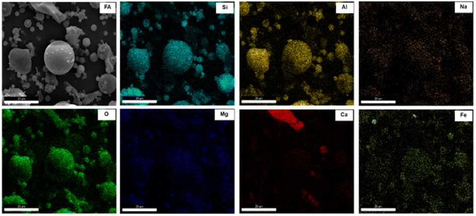 | ||
| Fig. 5 SEM-mapping images of FA. | ||
The content of alkali-metal oxides in FA was significantly reduced by a series of pretreatment methods. Inactive-phase minerals, such as mullite and quartz, are transformed into active-phase counterparts, such as sodium metasilicate and chlorite. These transformed minerals are readily soluble in sodium hydroxide solution, forming an alkaline solution enriched with Na, Al, and Si. Under suitable hydrothermal conditions, a Na-X molecular sieve of high purity can be synthesized by adjusting the Si/Al ratio and alkalinity.
Characterization of the Na-X molecular sieve
The crystallization time plays an important role in the synthesis of molecular sieves, which affects the nucleation and growth stages of molecular-sieve precursors.33 Crystallinity was gauged based on the aggregation peak areas at 2θ = 6.10°, 9.98°, 11.72°, 15.45°, 20.07°, 23.34°, 26.68° and 30.97° of the molecular-sieve products. The crystallinity of the 20 h product was normalized to 100%.34 Compared with this standard, the relative crystallinity of products at other times was calculated. In the present study, XRD was used to analyse the crystal phase of the high-iron fly-ash-based Na-X molecular sieve at times of 0 h, 3 h, 3.5 h, 8 h and 20 h. These assessments results are presented in Fig. 6.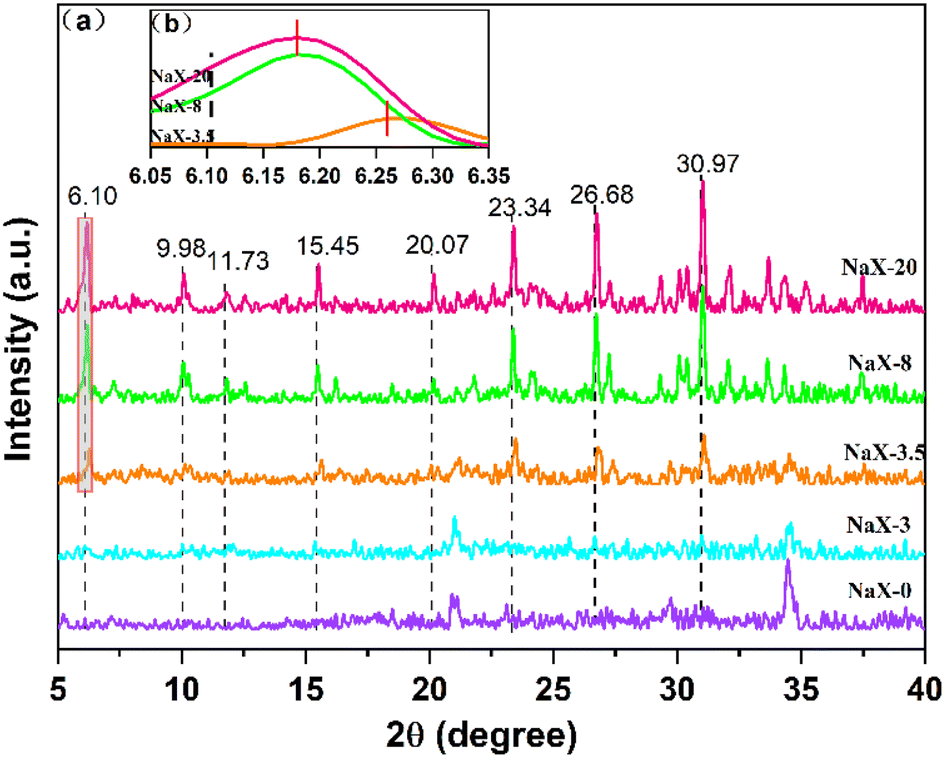 | ||
| Fig. 6 (a) XRD spectra of NaX-0, NaX-3, NaX-3.5, NaX-8 and NaX-20. (b) Partial enlarged image of NaX-3.5, NaX-8 and NaX-20. | ||
Fig. 6a reveals that the initial phase at 0 h is primarily aluminosilicate gel peaks (No. 35-0424). The persistence of this phase is evident at 3 h, where crystals of the Na-X molecular sieve were yet to manifest. Not until 3.5 h into the crystallization does the emergence of Na-X molecular sieve characteristic peaks (No. 38-0237) occur. However, the intensity of the Na-X diffraction peak is weak, and the relative crystallinity of the product is at 56.52%, indicating that the crystallization was not complete. At this time, the peak of the sodium aluminosilicate gel is still clearly visible. As the hydrothermal crystallization time prolongs, a progressive transformation of the aluminosilicate gel into Na-X is observed, characterized by the enhancement of the diffraction peak intensity. However, compared with the characteristic peak of standard Na-X, the peak position shifts to a high angle. At 8 h, the relative crystallinity ascends to 84.99%. At 20 h, a uniform and single-phase Na-X was formed.
Enhancement of Fig. 6a to obtain Fig. 6b reveals nuanced details at 2θ = 6.05°–6.35°. Compared with standard Na-X, the strong peak position of synthesized Na-X shifted to 6.18° at 6.10°. The plausible explanation for this deviation could be attributed to excessive impurities within the synthetic system or the potential adverse effects of iron oxides on pore structure.35 Contrarily, no characteristic peaks of iron oxides were detected through XRD analysis throughout the crystallization process. This absence could be ascribed to the even distribution of iron species on the molecular-sieve surface or encapsulation of aggregated iron species in the molecular-sieve structure.36
Fig. 7 presents SEM of the solid-phase products of the molecular sieve obtained at varying crystallization times. At 0 h (Fig. 7a), the solid phase is composed predominantly of amorphous materials interspersed with a small quantity of flaky structures. There was diverse dispersion of these amorphous particles, with some exhibiting optimal dispersibility, while others agglomerating into clusters.37 At 3 h (Fig. 7b), flaky structures dominate the composition, accented by an emergence of columnar particles formulated from these flaky constituents.38 At 3.5 h, the complexity of the composition escalates (Fig. 7c), where the enduring presence of flaky materials coexists with the emergence of regular small particles. This emergence signals the initiation of the assembly processes, that is, the free state of small molecules or structural units into crystalline form. At 4 h (Fig. 7d), a transitional phase becomes apparent. Although spherical particle aggregates still exist prominently, a significant shift towards the formation of small granules from amorphous particles is noticed. The persistence of spherical particle aggregates underscores an underdeveloped crystalline structure of molecular sieves on the aggregated particles of the amorphous gel.28 At the 20 h (Fig. 7e), a dramatic transformation is unveiled. The solid phase is now replete with octahedral crystals of the molecular sieve, signifying a substantial diminution in the proportion of amorphous aggregates.39
 | ||
| Fig. 7 SEM images of NaX-0 (a), NaX-3 (b), NaX-3.5 (c), NaX-4 (d), and NaX-20 (e). | ||
FTIR spectroscopy is used to analyse the solid-phase products of synthesized Na-X at different times; the results are depicted in Fig. 8. The peak at 1640 cm−1 attributes to the stretching vibration of hydroxyl groups adsorbed in water. At 0 h, a faint characteristic band of the double six-membered ring is observed at 560 cm−1. The external and internal linkages of TO4 (T = Si or Al) tetrahedrons are discernible at 670 cm−1 and 750 cm−1, respectively, albeit with low intensity. This suggests the loose connection of [TO4] in the gel phase and disordered state of the double six-membered ring and [TO4], thereby displaying the diverse polymerization states of Si and Al fragments.38,40,41 At the Initial stage of crystallization, the presence of low-molecular-weight aluminosilicate precursors, such as six-membered rings, which has high activity and undergo structural rearrangement during crystallization, fostering Na-X zeolite crystal nuclei growth. The enhancement of the bending vibration band of the T–O bond is evident at 460 cm−1 at 3 h and 3.5 h, alongside the emergence of the antisymmetric stretching vibration band of the internal and external connections of TO4 between 900 cm−1 and 1100 cm−1.42 These bands precisely aligned with the typical Na-X, confirming the formation of a characteristic Na-X skeleton structure post-crystallization. A pronounced increase in the intensity of characteristic peaks is observed after 20 h. This intensification signals the orderly arrangement of Si–Al fragments of varying polymerization states as the hydrothermal reaction progresses. Notably, the narrow peak shape of the T–O antisymmetric and symmetric stretching vibrations within [TO4], and the T–O bending vibration band, attests to a highly symmetrical and regular internal arrangement, thereby marking the transition from amorphous to crystalline structures.43,44 In essence, the crystallization of the molecular sieve underscores a transformative journey from a gel state to Na-X, which mainly occurs in the gel phase, and the gradual ordering of the gel structure is obvious.
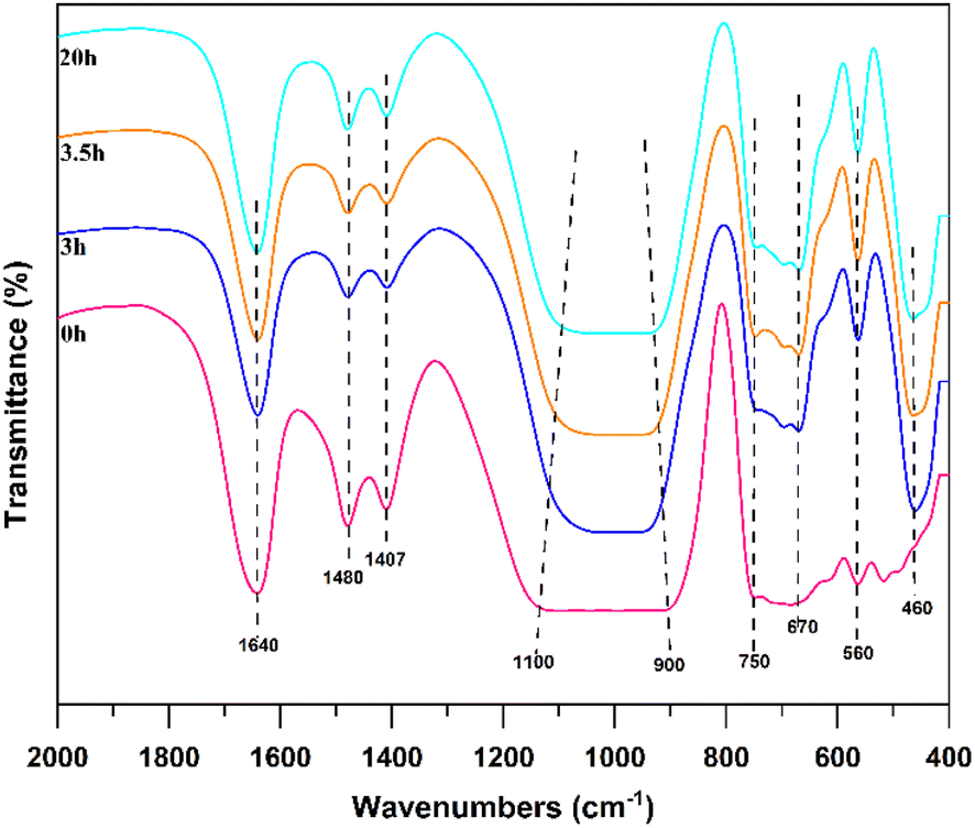 | ||
| Fig. 8 FTIR spectra of NaX-0, NaX-3, NaX-3.5, and NaX-20. | ||
Variation of Fe in synthesis processes
The SEM-mapping of iron in the pretreatment process and Na-X are shown in Fig. 9. | ||
| Fig. 9 Fe-mapping images of FA (a), HC (b), AL (c), AF (d), and NaX-20 (e). | ||
Examination of FA (Fig. 9a) and HC (Fig. 9b) reveals that a minor proportion of Fe manifests as a distinctly enriched phase, which is attributed to the presence of iron microbeads and hematite in fly ash.45 Most Fe is uniformly disseminated throughout the sample, which is due to the incorporation of Fe into the mullite lattice during fly ash combustion, eventually forming a solid melt. This distribution proves that the part of Fe is involved in the genesis of aluminosilicate in fly ash, which complicates the removal of Fe. Inspection of AL (Fig. 9c) and AF (Fig. 9d) delineates a homogenous distribution of Fe, affirming that the residual Fe is evenly dispersed post-pretreatment.46 In Na-X (Fig. 9e), a consistent distribution of Fe is discernible, signalling integration of a portion of Fe into the molecular-sieve framework or its highly dispersed presence on the molecular-sieve surface.47 This observation is congruent with preceding XRF findings.
The transformation of Fe during the synthesis of Na-X was investigated employing UV-Raman and UV-Vis spectroscopies for detailed characterization and analysis, as seen in Fig. 10 and 11.
 | ||
| Fig. 10 UV-Raman spectra of NaX-0, NaX-3, NaX-3.5 and NaX-20. | ||
Fig. 10 reveals that at 0 h, the highly dispersed surface iron species (543 cm−1), primarily exists as oxides.48,49 At 3 h, a notable decrease in the peak intensity of these dispersed iron species is observed at 537 cm−1. This decrease is related to the ongoing reaction within the solid material and incipient formation of molecular-sieve crystal nuclei, which promotes the transformation of the surface iron oxide species to iron in the skeleton. The peaks of iron species within the skeleton31 at 510 cm−1 and 1060 cm−1 are scarcely discernible at 0 h and 3 h. This observation underscores the predominance of iron-oxide species within the fly ash incorporated in the solid material during the initial crystallization phase. However, nuanced examination of the expanded segment of the image unveils the emergence of faint peaks at 1063 cm−1 and 512 cm−1 during 3.5 h, which are attributable to the antisymmetric and symmetric stretching vibrations of skeleton iron, respectively. Additionally, a faint spectral peak at 913 cm−1, ascribed to surface hexagonal Fe–O species, is discernible.50,51 This spectral evolution underscores the reduction of surface-dispersed iron species concurrent with the appearance of skeleton iron species as crystallization progresses. At 20 h, intensified peaks at 1060 cm−1 and 505 cm−1 corroborates increased content of skeleton iron within the molecular sieve, while the near-absence of a peak for surface iron species at 540 cm−1 suggests their integration into the molecular-sieve skeleton structure overextended crystallization. Nevertheless, the persistence of the Fe–O peak near 930 cm−1, indicative of surface six-coordination,52 attests to the incomplete integration of Fe into the skeleton.
As seen in Fig. 11, samples crystallized for 0 h, 3 h and 3.5 h had significantly wider absorption bands at 200–300 nm, with maximum absorption wavelengths of 235 nm and 268 nm. This is due to the different presence form of Fe,. In the sample before complete crystallization, there is a six-coordination Fe–O charged transition (235 nm), while the four-coordination Fe–O charged transition (268 nm) is weaker than that of the fully crystallized sample.53 According to the XRD pattern of the previous crystallization process, the molecular sieve has not been crystallized completely before 3.5 h, and the regular pore structure of the molecular sieve has not been formed. Hence, there are no tetracoordinate skeleton iron species in samples at 0 h and 3 h, and most of them exist in the form of iron oxides.54 After 3.5 h, the skeleton structure of the molecular sieve was formed, and the tetrad Fe–O charged transition at 268 nm was enhanced compared with that at 0 h and 3 h, as well as the spectral intensity at 268 nm was gradually enhanced with the extension of the crystallization time. The absorption peak at 300–350 nm is the d–d charge transition peak of Fe species at the skeleton site of the molecular sieve. In general, it is believed that the d–d transition peak is generated by the quad-coordination Fe species at the skeleton site, and the coordination bond between the central Fe and adjacent Si results in energy-level splitting, thereby leading to d–d transition of Fe species in the skeleton.46 It indicates that there may be no iron species in the skeleton position before 3.5 h, that most of them exist in the form of iron oxide, and a small portion in the amorphous Fe–O species had six coordination. After 3.5 h, most of the pore skeleton structure of the molecular sieve has been formed, and iron existed mainly in the form of four-coordinate skeleton iron, but iron oxide is present.
 | ||
| Fig. 11 UV-Vis spectra of NaX-0, NaX-3, NaX-3.5 and NaX-20. | ||
UV-Raman and UV-Vis characterization results are used to speculate the changes of iron in the synthesis process, as shown in Fig. 12. At the initial stage of crystallization, iron in the sol state is highly dispersed in the whole reaction system, and the Si–Al–O structure of the molecular sieve first condensates and polymerizes to form an ordered pore structure. In the middle stage of crystallization, highly dispersed six-coordinated iron oxide enters the silica-alumina structure. At the later stage of crystallization, the order of the molecular-sieve skeleton structure reaches a certain degree, and the highly dispersed six-coordinated iron oxide species are embedded in the skeleton structure. At this time, Fe–O bonds are formed and, finally, the four-coordinated iron species in the skeleton site are formed.
 | ||
| Fig. 12 Schematic diagram of the iron changes during the synthesis processes. | ||
Adsorption of Na-X for low-concentration CO2
 | ||
| Fig. 13 N2 adsorption–desorption isotherm and pore size distribution of NaX-20. | ||
 | ||
| Fig. 14 Breakthrough curve of adsorption of a low concentration of CO2 by a Na-X molecular sieve. | ||
| Sample | Pore size distribution/nm | Specific surface area/m2 g−1 |
|---|---|---|
| NaX-20 | 0.46–0.71 and 4.60 | 646.634 |
| NaX-C55 | 0.90–1.00 | 700.600 |
The permeation duration for the two molecular sieves spanned approximately 16–18 minutes, with NaX-20 exhibiting a permeation phase that was 2–4 min longer compared to that of NaX-C. However, the adsorption capacity of NaX-20 at 3.70 mmol g−1 was marginally inferior to that of NaX-C at 3.89 mmol g−1, representing 95.11% of the performance of NaX-C.
The effect of NaX-20 in this study is equivalent to that of NaX-C. It can be seen from Table 2 that, although the specific surface area of NaX-20 and NaX-C is not significantly different, the NaX-20 prepared in the present study has a micro-mesoporous structure. The presence of micropores is instrumental in facilitating CO2 adsorption, whereas mesopores are beneficial for accelerating CO2 diffusion.56 Additionally, the pore dimensions of NaX-20 exceed the critical molecular diameter of CO2 (0.28 nm). During the synthesis phase, Fe2+ and Fe3+ released via the alkali dissolution of iron engage in the formation of the zeolite framework as compensating cations.57 These ions are assimilated by the anionic zeolite framework on the molecular sieve structure, with ionic iron having a contributory role in CO2 adsorption.
 | ||
| Fig. 15 Adsorption performance of Na-X at different temperatures. | ||
| Temperature | 25 °C | 40 °C | 60 °C |
|---|---|---|---|
| Adsorption capacity (mmol g−1) | 3.70 | 2.43 | 2.32 |
| Breakthrough time (min | 24 | 8 | 4 |
Temperature plays an important role in the adsorption breakthrough process. The increase in temperature shortens the breakthrough time of CO2 and reduces the adsorption capacity of CO2. When the temperature increases from 25 °C to 60 °C, the capacity for CO2 adsorption decreases by about 1.5 mmol g−1. The adsorption process is an exothermic reaction. The increase in temperature will inhibit the forward progress of the reaction, which is not conducive to adsorption, thereby reducing the adsorption capacity and shortening the breakthrough time. Therefore, selection of a suitable lower temperature is beneficial to the adsorption treatment of CO2.59
Fig. 16 reveals that the data were well fitted by the Bangham model, which has a correlation coefficient exceeding 0.99. This indicates that the adsorption principle of Na-X for a low concentration of CO2 is more in line with the pore diffusion dominated by physical adsorption. After CO2 molecules diffuse into the molecular sieve pores, they are mainly adsorbed in the molecular sieve by intermolecular forces such as van der Waals force rather than chemical bonds.62
 | ||
| Fig. 16 Data of adsorption capacity with time and its fitting curves using quasi-first-order, quasi-second-order, and Bangham models. | ||
Fig. 17 reveals that the entire adsorption rate and adsorption capacity could be determined by one or more steps. The fitting data of the adsorption capacity qtand time t0.5are straight lines without passing through the origin, indicating that the entire adsorption process is controlled by multiple steps. The data are divided into three linear correlation stages, with an adsorption rate constant of k1 > k2 > k3 and a diffusion boundary layer thickness ofC1 < C2 < C3. This indicates that the adsorption rate gradually slows down, the diffusion resistance gradually increases, and, finally, the adsorption equilibrium is reached60,61 (Table 4).
 | ||
| Fig. 17 Curve fitted by the intraparticle diffusion model. | ||
| Dynamic model | Parameter | |
|---|---|---|
| Quasi-first order | R2 | 0.95626 |
| k1 | 0.01535 | |
| Quasi-second order | R2 | 0.93846 |
| k2 | 0.01650 | |
| Bangham | R2 | 0.99902 |
| k | 0.12488 | |
| W-M intraparticle diffusion | R12 | 0.99964 |
| k1 | 4.69028 | |
| C1 | 0.19849 | |
| R22 | 0.96784 | |
| k2 | 2.42822 | |
| C2 | 86.28666 | |
| R32 | 0.63139 | |
| k3 | 0.07828 | |
| C3 | 367.50848 | |
Conclusions
In summary, this work synthesized a Na-X molecular sieve from high-iron fly-ash, and the product was used for the adsorption of low-concentration CO2. Though pretreatment and hydrothermal synthesis, high-iron fly-ash was successfully transformed to the Na-X molecular sieve, which had a singular crystalline phase, optimal crystallinity, and octahedral morphology. In addition, the Na-X molecular sieve presented a high specific surface area of 646.634 m2 g−1 and rich pore structure, which is beneficial for CO2 adsorption. The adsorption capacity is 3.70 mmol g−1, reaching 95.11% that of the commercial Na-X molecular sieve.Author contributions
Jiaxing Guo and Hong Wu contributed to the formulation and evolution of overarching research aims, as well as writing and editing the manuscript. Jiaxing Guo and Yao Wei conducted measurements, collected and analysed data, and drew the figures in the manuscript. Yingju Miao, Jingyuan Qu and Ping Wang collected and analysed data to obtain data for CO2 adsorption.Conflicts of interest
There are no conflicts of interest to declare.Acknowledgements
This work was supported financially by the Guizhou Provincial Creative Team Project of Coal Clean Processing and Utilization (qianheKYzi [2020]027), Scientific Research Fund for High-level Talents of Liupanshui Normal University (LPSSYKYJJ202301), Guizhou Provincial Key Laboratory of Coal Clean Utilization (qiankehepingtairencai [2020]2001), Provincial First-Class Undergraduate Major Construction Points of Liupanshui Normal University (GZSyIzy202105), New Engineering Research and Practice Cultivation project of Liupanshui Normal University (LPSSYxgk201804), Top Science and Technology Talents Project of Guizhou Education Department (qiankeji [2022]090), Liupanshui Normal University (LPSSYCYFZ202101), High-Level Talent Project of Liupanshui Normal University (LPSSYKYJJ202302), Educational Teaching Reform and Research of Liupanshui Normal University (LPSSYkcszjg202110, 2022-07 027), Guizhou Provincial Youth Talent Development Project (qianjiaoheKYzi [2022]052), Liupanshui Normal College Scientific Research Project (LPSSYQNPY202102), and Foundation of Liupanshui Normal University (LPSSYLPY202206).References
- H. E. Guangyao, W. Bing, S. Pengcheng, B. Weiren, C. Liping, H. Zhanggen, W. Jiancheng and H. Li'Na, Clean Coal Technol., 2021, 27, 48–60 Search PubMed.
- X. Zhang, C. Li, S. Zheng, Y. Di and Z. Sun, Int. J. Miner., Metall. Mater., 2022, 29, 1–21 CrossRef CAS.
- F. U. Ke-ming, L. U. Mai-xi and Z. Hong, Multipurp. Util. Miner. Resour., 2007, 10–13 Search PubMed.
- W. Lianfeng, W. Minghua, L. Jianghua, Z. Xiaoyan and Z. Yuchun, J. Mater. Metall., 2013, 12, 58–61 Search PubMed.
- Q. Xavier, P. Felicia, A. Andres and L. Angel, Fuel, 1997, 76, 793–799 CrossRef.
- K. S. Hui and C. Y. H. Chao, Microporous Mesoporous Mater., 2006, 88, 145–151 CrossRef CAS.
- C. Yan-guang and Y. U. Feng-ming, Bull. Chin. Ceram. Soc., 2015, 34, 727–732 Search PubMed.
- B. Wang, L. Ma, L. Han, Y. Feng, J. Hu, W. Xie, W. Bao, L. Chang, Z. Huang and J. Wang, Chem. Eng. Sci.: X, 2021, 10, 100089 CAS.
- X. Jin, N. Ji, C. Song, D. Ma, G. Yan and Q. Liu, Procedia Eng., 2015, 121, 961–966 CrossRef CAS.
- X. He, B. Yao, Y. Xia, H. Huang, Y. Gan and W. Zhang, Power Technol., 2020, 40–46 CrossRef.
- A. M. Cardoso, A. Paprocki, L. S. Ferret, C. M. N. Azevedo and M. Pires, Fuel, 2015, 59–67 CrossRef CAS.
- X. Ren, S. Liu, R. Qu, L. Xiao, P. Hu, H. Song, W. Wu, C. Zheng, X. Wu and X. Gao, Microporous Mesoporous Mater., 2020, 295, 109940 CrossRef CAS.
- K. Mee and Y. Jo, Journal of Material Cycles & Waste Management, 2010, 212–219 Search PubMed.
- R. Panek, M. Wdowin, W. Franus, D. Czarna, L. A. Stevens, H. Deng, J. Liu, C. Sun, H. Liu and C. E. Snape, J. Co2 Util., 2017, 22, 81–90 CrossRef CAS.
- S. Boycheva, D. Zgureva, V. I. Miroslava, Y. Kalvachev, H. Lazarova and M. Popova, J. Hazard. Mater., 2018, 361, 374–382 CrossRef PubMed.
- P. Margarita, B. Silviya, L. Hristina, Z. Denitza, L. Karoly and S. Agnes, Catal. Today, 2019, 357, 518–525 Search PubMed.
- S. Boycheva, D. Zgureva, K. Lazarova, T. Babeva, C. Popov, H. Lazarova and M. Popova, Materials, 2020, 13, 2014 CrossRef CAS PubMed.
- M. Yingju, L. Minglei, H. Jiangliang, L. Lin and K. Deshun, Inorg. Chem. Ind., 2014, 46, 8–10 Search PubMed.
- H. U. Jianquan, D. Mengqiang, G. Yuan, Z. Xuetao, T. U. Kecai, L. Wanpeng and D. Cong, Ind. Water Treat., 2022, 42, 73–77 Search PubMed.
- L. Qi, K. Liu, R. Wang, J. Li, Y. Zhang and L. Chen, Acs Omega, 2020, 5, 31665–31672 CrossRef CAS PubMed.
- Q. Ya-nan, K. Zi-hua, N. Deng-pan, L. Bin and W. Yi-yi, Mod. Chem. Ind., 2022, 42, 165–169 Search PubMed.
- M. Ying-ju, S. Qiu-yu, Z. Yu and L. Ming-lei, Bull. Chin. Ceram. Soc., 2016, 35, 1260–1264 Search PubMed.
- H. Yu-bin, Q. Jue-shi and Z. Jian-ye, J. Funct. mater., 2009, 40, 1787–1790 Search PubMed.
- L. Xue-Wu, D. Bao-Guo, W. Jin-Tao and W. Xiao-Juan, J. Jishou Univ., Nat. Sci., 2016, 37, 43–46 Search PubMed.
- H. Su-yang, L. Xin-bo, T. Jian-feng, L. Guang-yan, S. Yong-biao, H. Yi-huai and L. Qiu-ying, Chem. Ind. Eng. Prog., 2022, 41, 153–160 Search PubMed.
- L. Ma, Y. Feng, M. Zhang, Q. Zheng, B. Wang, L. Han, Y. Li, L. Chang, W. Bao and J. Wang, J. Cleaner Prod., 2020, 275, 122977 CrossRef CAS.
- L. Qing, C. Guilan, S. Yuzhu, Y. Yinmei, Q. Xiuchen and Y. Jianguo, Ind. Eng. Chem. Res., 2013, 52, 18184–18191 CrossRef.
- L. Han, W. Ren, B. Wang, X. He, L. Ma, Q. Huo, J. Wang, W. Bao and L. Chang, Fuel, 2019, 253, 1184–1192 CrossRef CAS.
- E. I. Basaldella, R. M. T. Sanchez and J. C. Tara, Clays Clay Miner., 1998, 46, 481–486 CrossRef CAS.
- X. Yu, W. Xiaohui, M. A. Shuhua and L. Zhihong, J. Build. Mater., 2021, 24, 663–670 Search PubMed.
- Z. Xihuan and M. Hongwen, Acta Metall. Sin. (Engl. Lett.), 2013, 33, 31–37 Search PubMed.
- S. Hui, S. Ben-xian, L. Ji-chang and D. Ji-Hong, J. East China Univ. Sci. Technol., Nat. Sci. Ed., 2008, 34, 172–177 Search PubMed.
- Z. Lihong, L. Qiang, L. Yaqian, L. Xian and Z. Wenqi, R. Soc. Chem., 2022, 4212–4225 Search PubMed.
- B. Yu-Shui and L. Gong-Xuan, Acta Chim. Sin., 2004, 62, 1981–1987 Search PubMed.
- Y. Liang, L. Xueyin, H. Hanwei, Z. Haisheng and X. Dongmei, Mater. Sci. Eng. Powder Metall., 2013, 18, 270–275 Search PubMed.
- L. Dongxia, L. I. Bing, W. Quanyi, T. Peng, L. Zhongyi and L. Zhongmin, Chem. Res. Chin. Univ., 2020, 41, 2442–2448 Search PubMed.
- L. Ma, L. Han, S. Chen, J. Hu, L. Chang, W. Bao and J. Wang, Fuel Process. Technol., 2019, 189, 39–48 CrossRef CAS.
- H. Jiang, D. Wang, J. Tan, Y. Chen, Y. An, Y. Chen, Y. Wu, H. Sun, B. Shen, D. Wu, J. Liu, H. Ling, J. Zhao and Y. Tong, Ind. Eng. Chem. Res., 2020, 59, 9997–10009 CrossRef CAS.
- W. Qinming, W. Yeqing, M. Xiangju and X. Fengshou, Chem. Res. Chin. Univ., 2021, 42, 21–28 Search PubMed.
- Y. Dongqing, W. Yongrui, M. Xuhong and S. Xintian, Sci. Sin.: Chim., 2014, 44, 138–145 Search PubMed.
- H. Qing-xun, S. Xue-Qin, T. Qiu-Xia and L. Hong-Hai, Petrochem. Technol. Appl., 2019, 37, 85–88 Search PubMed.
- F. Xie, S. Zhao, X. Bo, G. Li, J. Fei, E. M. A. Ahmed, Q. Zhang, H. Jin, S. Wang and A. Z. Lin, J. Mater. Chem. A, 2022, 11, 53–67 RSC.
- J. Borgatta, A. Paskavitz, D. Kim and J. G. Navea, Environ. Chem., 2016, 13, 902–912 CrossRef CAS.
- D. Valeev, A. Mikhailova and A. Atmadzhidi, Metals, 2018, 8, 533 CrossRef.
- G. Yan, X. Wang, X. Fu and D. Li, Catal. Today, 2004, 93–95, 851–856 CrossRef CAS.
- L. Weigang, L. Gangzi, J. Changzi and X. LIU, J. Mater. Chem. A, 2015, 3, 14786–14793 RSC.
- C. Yanguang, S. Jie, W. Xiaohui, Z. Yannan and D. Jitong, Bull. Chin. Ceram. Soc., 2021, 40 Search PubMed.
- Z. Changkun, H. Shuai, C. Yu and L. Xinyue, Environ. Chem., 2019, 38, 887–893 Search PubMed.
- G. Qiang, F. Fengtao, G. Meiling, F. Zhaochi and L. I. Can, Chin. J. Catal., 2012, 33, 106–113 CrossRef.
- J. Zhang, C. Yueying, L. Xiaolong, X. Hao, M. Xiangju, F. Zhaochi and X. Fengshou, Catalysis, 2019, 40, 1854–1859 CAS.
- L. Wang, S. Lin, K. Lin, C. Yin, D. Liang, Y. Di, P. Fan, D. Jiang and F. Xiao, Microporous Mesoporous Mater., 2005, 85, 136–142 CrossRef CAS.
- Z. Chunlei, W. Zhiyun and K. Qiubin, J. Mol. Catal., 1995, 9, 165–171 Search PubMed.
- L. Yuxiang, S. Huafeng, H. Bo, Y. Pinliang, F. Zhaochi and L. Can, Chinese Journal of Light Scattering, 2003, 15, 188–190 Search PubMed.
- Z. Wu, J. Yanyan, P. Han, D. Shaoying, L. Ying, Z. Jimei and W. Dongmei, Chem. Res. Chin. Univ., 2018, 39, 1985–1992 Search PubMed.
- H. Zhao, Y. Ma, J. Tang, J. Hu and H. Liu, J. Solut. Chem., 2011, 40, 740–749 CrossRef CAS.
- C. C. Kingkaew, K. Somkait and Y. Sujittra, Microporous Mesoporous Mater., 2017, 245, 8–15 CrossRef.
- X. Ren, S. Liu, R. Qu, L. Xiao, P. Hu, H. Song, W. Wu, C. Zheng, X. Wu and X. Gao, Microporous Mesoporous Mater., 2020, 295, 109940 CrossRef CAS.
- Y. Yu, D. Chen, S. Xie, Q. Sun, Z. Zhang and G. Zeng, J. Environ. Chem. Eng., 2022, 10, 107660 CrossRef CAS.
- J. Jin, K. Cui, P. Wu, G. Chen, Y. Wang and D. Liu, R. Soc. Chem., 2021, 45, 10331–10339 Search PubMed.
- A. K. Nayak and A. Pal, J. Mol. Liq., 2019, 276, 67–77 CrossRef CAS.
- J. Guo, Z. Zhai, L. Wang, Z. Wang, J. Wu, B. Zhang and J. Zhang, Environ. Pollut., 2017, 225, 175–183 CrossRef CAS PubMed.
- J. Luo, Y. Liu, C. Jiang, W. Chu, W. Jie and H. Xie, J. Chem. Eng. Data, 2011, 56, 4919–4926 CrossRef CAS.
| This journal is © The Royal Society of Chemistry 2024 |