Extending the lifetime of vanadium redox flow batteries by reactivation of carbon electrode materials†
Muhammad Adeel
Ashraf‡
abc,
Stylianos
Daskalakis‡
 bc,
Matthias
Kogler
bc,
Markus
Ostermann
bc,
Matthias
Kogler
bc,
Markus
Ostermann
 b,
Soniya
Gahlawat
b,
Seohee
Son
d,
Pavel
Mardilovich
d,
Markus
Valtiner
b,
Soniya
Gahlawat
b,
Seohee
Son
d,
Pavel
Mardilovich
d,
Markus
Valtiner
 bc and
Christian M.
Pichler
 *bc
*bc
aAvesta Battery and Energy Engineering, Doorn Noordstraat 10, 9400 Ninove, Belgium
bCentre for Electrochemical and Surface Technology, Viktor Kaplan-Straße 2, 2700 Wiener Neustadt, Austria
cVienna University of Technology, Institute of Applied Physics, Karlsplatz 13, 1040 Vienna, Austria
dEnerox GmbH, IZ NÖ-Süd Str. 3 Obj M36, 2355 Wiener Neudorf, Austria
First published on 27th March 2024
Abstract
The degradation and aging of carbon felt electrodes is a main reason for the performance loss of Vanadium Redox Flow Batteries over extended operation time. In this study, the chemical mechanisms for carbon electrode degradation are investigated and distinct differences in the degradation mechanisms on positive and negative electrodes have been revealed. A combination of surface analysis techniques such as X-ray photoelectron spectroscopy (XPS), Raman spectroscopy, and Electrochemical Impedance Spectroscopy (EIS) was applied for this purpose. In addition to understanding the chemical and physical alterations of the aged electrodes, a thermal method for reactivating aged electrodes was developed. The reactivation process was successfully applied on artificially aged electrodes as well as on electrodes from a real-world industrial vanadium redox flow battery system. The aforementioned analysis methods provided insight and understanding into the chemical mechanisms of the reactivation procedure. By applying the reactivation method, the lifetime of vanadium redox flow batteries can be significantly extended.
Introduction
Redox flow batteries (RFBs) have been considered a leading contender for stationary energy storage systems spanning the range from kW to MW.1–3 Implementation of renewable electricity generation on a large scale, by solar photovoltaic and wind, requires efficient and large-scale electric energy storage solutions due to the intermittent nature of these sources. Among various options, the vanadium redox flow battery (VRFB) has emerged as a particularly auspicious energy storage system. This is attributed to several strengths, including the ability to separately tailor power and energy capacity, a simple and straightforward cell and stack design, as well as rapid responsiveness, and a prolonged cycle lifespan.4The VRFB applications include especially large-scale energy storage systems for solar photovoltaic power plants and wind parks. These use cases demand both prolonged robustness and consistent output performance efficiency. Achieving these objectives necessitates a comprehensive investigation into the degradation processes affecting various components, of the VRFB system, such as the electrodes, the membrane, and the electrolyte.5 A major challenge concerning the longevity of VRFBs revolves around the electrochemical degradation of carbon-felt electrodes. It is expected that these electrodes should endure more than 10 years or approximately 3000–4000 cycles (assuming approx. 1 cycle per day).6,7 Commercially utilized carbon felt electrodes are typically subjected to chemical or thermal activation procedures to improve the electrochemical performance of the electrodes.8–11 This alteration influences the carbon sp2/sp3 ratio, the quantity and nature of oxygen functional groups, and the electrochemically active surface area. These alterations in material characteristics can have different effects on negative and positive electrodes, during operation. In the positive half-cell, a potential side reaction involves the overoxidation of carbon to CO2 (carbon corrosion) while in the negative half-cell, the hydrogen evolution reaction (HER) competes with the vanadium (V3+ → V2+) reaction. These side reactions were reported to lead to a reduction in electrochemically active surface area (ECSA) and towards the efficiency of the vanadium conversion process.12–14
The electrode degradation in vanadium redox flow batteries has been investigated in previous studies and focussed mainly on the positive electrode, while as main deactivation mechanisms surface oxidation of the carbon electrode was suggested.15–17 Less studies focussed on negative electrode degradation. An example of this is Mazur et al., who investigated the long-term stability of negative electrodes using two different types of graphite felts (rayon-based and PAN-based) for over 2000 cycles. Their results revealed significant stability differences between the two carbon materials. X-ray photoelectron spectroscopy (XPS) indicated comparable changes in surface functionalization by the introduction of similar oxygen functional groups on both felt types. However, the decline in sp2-hybridized carbon content and the increase in sp3-hybridized carbon content are notably more pronounced in the less stable polyacrylonitrile-based felt.18 Derr et al. studied the electrochemical degradation of electrodes through electrochemical impedance spectroscopy (EIS) at different states of charge and found a stronger deactivation of carbon felts at the negative electrode. Their scanning electron microscopy (SEM) results indicated a peeling of the fibres’ surface structure, leading to a loss of electrochemical active surface area (ECSA) and ultimately to the loss of overall performance of the battery.5 Singh et al. also explored the degradation mechanism in carbon electrodes and their electrochemical results suggested a more pronounced deactivation at the negative electrode compared to the positive. They confirmed this degradation via Raman spectroscopy by showing a decrease in structural defects at the negative electrode and an increase in defects at the positive electrode.19 In previous studies, nearly exclusively, artificially aged electrodes (obtained by laboratory tests) have been used and no strategies to improve the degradation stability or reactivate the spent electrodes have been made.
In the current work, we investigated carbon electrodes that have been utilized in a real-world VRFB system for several years. With this approach, it can be guaranteed, that the degradation mechanisms in real-world systems and laboratory experiments are indeed comparable. A direct comparison between real-world and artificially aged electrodes was provided. Besides probing the electrochemical performance of pristine and various aged electrodes, advanced surface analysis by X-ray photoelectron spectroscopy (XPS), scanning electron microscopy (SEM), and Raman spectroscopy was performed, to describe the molecular degradation mechanisms in carbon electrodes. Additionally, we were able to implement a reactivation process, that greatly reversed the electrode aging effects. The reactivated electrodes demonstrated a comparable electrochemical performance compared to fresh electrode materials. Therefore, this study does not provide additional insight into the exact electrode degradation mechanisms but for the first time demonstrates a solution for reversing the degradation effects on electrodes. This can potentially increase the overall lifetime of VRFB systems significantly and enables a promising recycling prospect for carbon electrodes, improving the sustainability and recyclability of the whole VRFB system significantly.
Experimental part
Materials and chemicals
Aged carbon felt electrodes were provided by Enerox GmbH from a field-operated system, that was operational for 10 years. These materials were labelled as “Aged real”. As fresh electrodes thermally activated carbon felts (793 K) provided by SGL Carbon SE are used as received. These electrodes were labelled as “pristine”. The same electrodes were used for artificial aging. The artificial aging was performed in an electrochemical flow cell (Electrocell MicroFlowCell with 10 cm2 electrode area, electrode compartments were separated by a fumasep FAP-450 anion exchange membrane provided by Fumatech) by continuous charging/discharging at a constant current of 100 mA cm−2 with cutoff voltages of 2.1 V and 0.3 V for 50 cycles with 5 minutes rest in between individual cycles. More extreme cutoff voltages were chosen for the artificial aging test, compared to the flow cell cycling, which was performed in the same cell setup at commonly used cutoff voltages of 1.6 V and 0.8 V for 30 cycles. The more extreme values will induce higher electrochemical stress on the carbon materials, leading to accelerated material degradation.20 Commercially available, VIII/VIV premixed electrolyte (GFE) was pumped with a flow rate of 10 mL min−1 to ensure steady-state conditions. After cycling the aged felts were cleaned with Milli-Q water in an ultrasonication bath and dried at 80 °C for 30–40 minutes. The obtained felts were labelled “artificially aged”. The optimized reactivation process was the same for real and artificially aged felts and consisted of a thermal re-activation treatment at 793 K for 1 hour in an air atmosphere. Materials undergoing this procedure were labelled as “Aged real re-activated” and “Aged artificial re-activated” respectively. For the cyclic voltammetry (CV) and electrochemical impedance spectroscopy (EIS) experiments, 15 mM VOSO4. xH2O (Thermo Scientific) in 2 M H2SO4 was used as an electrolyte.Material characterization
The electrochemical characterization was performed at room temperature using a three-electrode setup with a Biologic SP-240 potentiostat. The electrochemical test setup consists of a 3D printed cap with custom-made sample holders, always exposing the same geometric electrode area (images of the cell are shown in Fig. S1†) and keeping a defined distance between the working, counter (1 cm), and reference electrodes. Pristine thermally activated carbon felts were used as counter electrodes (4.5 cm2) for all the experiments while the aged and reactivated felts were used as working electrodes (1 cm2). Electrode felts were soaked for at least 1 h before performing experiments, to ensure a complete and even wetting of the electrode. A Hg/Hg2SO4 reference electrode with a saturated K2SO4 inner electrolyte was used. The cyclic voltammetry was performed in the potential range of −1.5 V to −0.4 V vs. Hg/Hg2SO4 (K2SO4 sat.) on the negative side and −0.5 V to 1.0 V vs. Hg/Hg2SO4 (K2SO4 sat.) on the positive side at scan rate 20 mV s−1. The electrochemical impedance spectroscopy (EIS) measurements were performed in the potentiostatic mode at −1.1 V vs. Hg/Hg2SO4 (K2SO4 sat.) on the negative side and 0.4 V vs. Hg/Hg2SO4 (K2SO4 sat.) on the positive side with a frequency range from 1 MHz to 50 mHz. The acquired EIS spectra were matched with suitable equivalent circuit models using the Zview 2 software tool (Scribner and Associates). The electrochemical surface area (ECSA) of the felts was determined in 2 M H2SO4 electrolyte in the potential window of −0.4 V to 0.2 V vs. Hg/Hg2SO4 (K2SO4 sat.) at different scan rates of 5 mV s−1, 10 mV s−1, 20 mV s−1, 50 mV s−1, 100 mV s−1, and 200 mV s−1.Electron microscopy was conducted using a Zeiss Sigma EDVP scanning electron microscope (SEM), equipped with an Ametek EDAX analyser for energy-dispersive X-ray spectroscopy (EDX) analysis. Raman spectra were measured using a LabRam Aramis Spectrometer from Horiba Jovin Yvon (Germany) with a wavelength of 532 nm. A 100× microscope objective was used.
X-ray photoelectron spectroscopy (XPS) measurements were performed using a Versa Probe III spectrometer (Physical electronics GMBH) at the ELSA cluster TU Vienna. Monochromated Al Kα (1486.6 eV) was used as radiation, with the beam diameter set to 100 μm and the beam voltage to 15 kV. The samples were mounted on a conductive carbon tape to avoid the charging effect. Survey scans of all samples were recorded at a pass energy of 140 eV and a step size of 0.125 eV. High resolution core level spectra were recorded at a pass energy of 27 eV and a step size of 0.05 eV. CasaXPS (Fairley, N. CasaXPS Version 2.3.17dev6.3y) was used to process the spectra. The C 1s spectra were corrected with a U 3 Tougaard-type background. sp2 hybridized carbon was fitted with an asymmetric peak shape, while the remaining species were deconvoluted with Gaussian–Lorentzian peak shapes. Their position was determined with respect to sp2 carbon, with their FWHM restricted to sp3 carbon. All spectra were binding energy corrected to the sp2 carbon signal at 284.4 eV.
Results and discussion
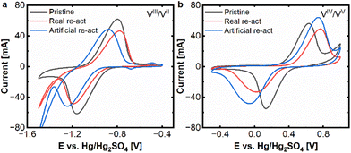
At first cyclic voltammetry was applied to assess the electrochemical performance of pristine and aged carbon felts. As key parameters for assessing the electrode performance, the peak current and distance between the oxidation and reduction peak were selected. Fig. 1 shows the comparison of the aged felts with the pristine felts at both electrodes.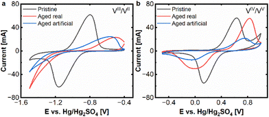 | ||
| Fig. 1 CV (20 mV s−1) real and artificial aging: (a) negative side and (b) positive side. Measured at a scan rate of 20 mV s−1 in an electrolyte of 15 mM VOSO4. xH2O dissolved in 2 M H2SO4. | ||
Clear signs of degradation are found for both aged electrodes. At the negative side, there is a clear decrease of the peak currents in the oxidative and reductive peaks for the real aged felt (red curve) as well as for the artificially aged one (blue curve), compared to the pristine electrode (black curve). For the reductive half-reaction (VIII to VII) the deactivation of the aged electrodes is so severe, that no clear peak can be found in the observed potential window. The vanadium reduction is superimposed by the onset of hydrogen evolution, hence no peak distance between oxidative and negative peak can be determined anymore. The oxidative peak shows a shift from approx. −0.80 V to −0.50 V (aged real) resp. −0.56 V (artificially aged) (vs. Hg/Hg2SO4) and a reduction of peak current from approx. 60 mA to 20 mA for aged real and artificial, which are also clear signs of degradation.
In the positive half-cell, the deactivation process is still visible but less pronounced. An increase in the peak separation from ΔEp = 499 mV to 833 mV (aged real) and 798 mV (artificially aged), respectively, can be found. While for the real aged samples, there is a decrease in the peak current for the reductive peak (from 47 mA to 26 mA), the oxidative peak stays in a similar range of about 55 mA. For the artificially aged samples, however, both peak currents are significantly reduced, to approx. 20 mA and 14 mA for oxidation and reduction. From these experiments, it can be determined that the electrode deactivation is more severe on the negative side and that real and artificial aging result in very similar behaviour on the negative side, while on the positive side, the artificially aged samples demonstrated more severe deactivation phenomena.
The next step was the attempt to reactivate the aged samples and reinstate their electrochemical activity. For this purpose, the real and artificially aged carbon felt electrodes (positive and negative) were thermally treated at 793 K for 1 hour under air. The rationale behind this treatment is to mimic the thermal treatment process that carbon electrodes undergo before they are utilized in VRFBs. The effects of this initial temperature treatment have been described in several studies.21,22 Briefly, thermal treatment is expected to increase the electrode's surface areas and introduce active sites for the redox reactions. Hence, we assumed that a thermal reactivation could reinstate the active sites and therefore the electrochemical performance of the electrodes.
After the reactivation treatment, cyclic voltammetry was performed to evaluate the electrochemical performance of the reactivated electrodes. The results of these experiments are presented in Fig. 2a and b and demonstrate, that the reactivated electrodes exhibit indeed a very similar behaviour compared to the pristine electrodes. For the negative side, only a minor reduction of peak currents (from 60 mA to appr. 45 mA) remains. Even the peak separation for the reactivated felts is 360–400 mV in a similar range to the pristine one (360 mV). Only, the hydrogen evolution seems to be more pronounced for the reactivated samples.
On the positive side the reactivated samples and the pristine one exhibit peak currents of 50–60 mA for the oxidative peak and 30–45 mA for the reductive peak, while the reactivated real-aged felt shows the lowest current. The peak separations are 499 mV for the pristine and approx. 800 mV for the reactivated samples.
The CV experiments show that the reactivation process is successful for both electrodes, but especially for the negative one, where the severe deactivation of the aged samples, could be significantly alleviated.
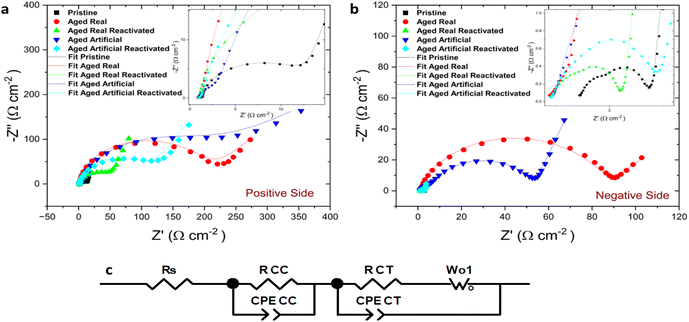
This behaviour was confirmed by the results from electrochemical impedance spectroscopy EIS measurements. Fig. 3 illustrates the electrochemical impedance response of the aged and reactivated felts compared with the pristine thermally activated felts at positive (Fig. 3a) and negative (Fig. 3b) sides. The EIS raw data of all measured samples is presented by symbols and the fitting of those with line, while an inset zooming in the high-frequency region is depicted. The EIS results are well-matched and confirm the same behaviour for the felts that we observed in the CVs. The starting point of the Nyquist plot is the solution resistance (RS) while the first semicircle at high frequencies indicates the contact charge resistance of the electrodes (RCC). In high to mid frequencies with bigger and broader semicircle radius the charge transfer resistance (RCT) indicates the electron transfer steps for the VO2+/VO2+ and V2+ V−3+ redox pairs, which is greatly influenced by the nature of active sites on the electrode surface.23 The straight line at low frequencies corresponds to the mass transport mechanism (diffusion) and as a result, two different mechanisms are present in the redox reactions on the electrodes. The Nyquist plots are fitted using an equivalent circuit (Fig. 3c) which incorporates the resistance of the electrolyte solution RS, the contact charge resistance RCC of the electrode, a constant phase element CPECC and a CPECT constant phase element representing the double layer capacitance (Cdl) in the medium frequency region, RCT the charge transfer resistance at the electrode–electrolyte interface, and the Warburg element Wo1, describing the mass transport diffusion effect in the low-frequency region.
As expected, a high RCT was observed for the real aged felts, and the artificially aged ones provided very similar values (Table 1). In the artificially aged electrodes, the RCC is higher than in the other measurements. The electrical contact within the system is worse and this difference might be caused by the lower conductivity of the samples after the more severe electrochemical treatment. There is only a minor difference in the solution resistance since the same electrolyte was used in all measurements. The results underline the findings from the CV experiments, namely that felts on both electrode sides indicate a decreased performance of the redox reactions because of degradation phenomena (the chemical nature of these phenomena will be discussed later). However, after the reactivation, the charge transfer resistance is moderately decreased on the positive side and more drastically on the negative side which confirms the findings from the CV results and indicates a recovery of the electrochemical performance.
| R S (Ω cm−2) | R CC (Ω cm−2) | R CT (Ω cm−2) | |
|---|---|---|---|
| Positive side | |||
| Pristine | 0.88 | 0.56 | 12.32 |
| Aged real | 0.83 | 0.57 | 199.6 |
| Aged real re-activated | 0.82 | 0.2 | 55.38 |
| Aged artificial | 0.92 | 2.23 | 180.3 |
| Aged artificial re-activated | 0.95 | 0.36 | 125.2 |
| Negative side | |||
| Pristine | 1.43 | 0.41 | 0.94 |
| Aged real | 0.85 | 0.32 | 84.36 |
| Aged real re-activated | 0.88 | 0.12 | 1.28 |
| Aged artificial | 0.96 | 6.64 | 45.67 |
| Aged artificial re-activated | 0.89 | 0.25 | 1.89 |
At low frequencies, all negative electrode samples exhibit diffusion behaviour, typical of the highly porous electrode. The impedance fitting of the positive side artificially aged electrode depicts a depressed semicircle and a low-frequency tail, which can be attributed to a charge transfer reaction at the electrolyte/electrode interface and semi-infinite diffusion in the boundary layer from the interface.24 The RCT values on the negative side were much smaller than those on the positive side indicating faster kinetics of the negative redox-couple, as the additional oxygen transfer step during the positive side redox reaction (VO2+/VO2+) is sluggish.25,26 The EIS experiments, therefore, confirm the findings of the CV experiments, and demonstrate that the reactivation process is indeed successful and especially effective on the negative electrode.
After probing the electrochemical behaviour of the carbon electrodes, the inherent material characteristics shall be investigated, to get a deeper understanding of the aging and the reactivation process.
The first investigated material characteristic was the electrochemical surface area (ECSA), which is determined for all the felts by performing cyclic voltammetry in pure 2 M H2SO4 at different scan rates between 5 to 200 mV s−1. From the slope of the peak currents, the double-layer capacitance (Cdl) of the electrodes can be obtained, which together with the specific capacitance (Csp) is used to obtain the ECSA.27 The calculation and results for the ECSA are shown in the ESI Fig. S2–10.† The ECSA for the pristine thermally activated felt is higher (27.4 cm2), compared to the real-aged negative (4.8 cm2) and positive (10.6 cm2) electrodes. Loss of ECSA is a known degradation mechanism for long-term cycling, caused by the peeling of the surface carbon layers in the fibres. The peeling effect itself is explained by repeated intercalation of sulphate ions during the charging/discharging cycles combined with mechanical stress from the pumped electrolyte.28 Surprisingly, the artificially aged felts do not show a reduction, but an increase in ECSA (36.7 cm2 and 50.7 cm2 for negative and positive). For artificial aging, the main deactivation is not the peeling mechanism, but deliberate, excessive hydrogen evolution. It has been reported that hydrogen evolution can also alter the surface morphology of carbon fibres, which can explain the observed ECSA increase.29 After thermal re-activation of the aged real felts, their ECSA increases again to 26.9 cm2 and 31.8 cm2 (negative and positive), while the re-activated artificially aged felts remain in the same order of magnitude with 45.4 cm2 and 40.4 cm2. This indicates, that the ECSA is not a completely reliable method to predict the electrochemical performance of the vanadium redox reactions and caution must be taken when interpreting these results. Even though, for the real-world aged samples the ECSA correspondingly changes with the de- and reactivation of the carbon electrodes.
As the next method, Raman spectroscopy was applied, to gain an insight into the defect structure of the carbon electrodes, as it is known, that carbon defects can serve as potential active sites for the vanadium redox reaction.30–32
For carbon materials, the ratio of D and G band peak intensities indicates the amount of disorder in the graphitic lattice. A higher ratio of D/G band peak intensities indicate a higher degree of structural disorder, resulting in a defective graphitic lattice and vice versa.33,34 The surface charge carrier density of the carbon materials can be determined by the ratio of 2D and G band (2D/G) in the Raman spectrum. An increase in D/G combined with a decrease in 2D/G ratios indicates therefore not only increasing defect concentration, but also signifies changes in the electronic structure and surface charge density.19 The Raman spectra along with the D/G and 2D/G ratios are displayed for all felts in Fig. 4 (peak fits are shown in Fig. S11†). It is assumed that the thermal treatment of the carbon felts, before utilization as electrodes for VRFBs, introduces defect sites. Therefore, the pristine felt exhibited the highest D/G ratio of 1.35 and the lowest 2D/G ratio of 0.53. The D/G ratio for the real aged felts for the negative and positive reduced to 0.82 and 1.25 respectively and 2D/G increased to 0.82 for the negative but decreased slightly for the positive one to 0.49. This again confirms the previous assumption that the aging of the negative electrodes, is more severe, resulting in larger changes and a greater loss of defects. Also, an increase in the 2D/G ratio suggests a decrease in charge carrier density. A similar trend was observed for the artificially aged felts, where the negative electrode exhibited a D/G band ratio of 1.32 and a 2D/G ratio of 0.59, and the positive electrode showed a D/G band ratio of 1.16 and the 2D/G band ratio was 0.48.
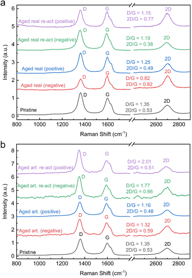 | ||
| Fig. 4 Raman spectra: (a) real aged and reactivated electrodes, (b) aged artificial and re-activated electrodes. | ||
However, the difference between negative and positive electrodes is not as pronounced as in real-world aging and the extent of defect loss (or reduced D/G ratio) is not as large on the negative electrode.
When analysing the reactivated samples an increase in the D/G band ratio and a decrease in the 2D/G ratio is especially pronounced for the negative electrodes. For the real-world aged negative electrodes, the D/G band ratio rises after reactivation to 1.19 and the 2D/G is lowered to 0.38. For the reactivation of the artificially aged felts the D/G band ratio is even 1.77 and the 2D/G band ratio 0.66. In both cases, the reactivation increases the defect concentration and the charge carrier density.
For the positive electrodes, the reactivation shows a similar trend. The D/G band ratios rise to 1.15 and 2.01 on for the reactivated real-world and artificially aged samples respectively, while the 2D/G ratios are 0.77 and 0.51 for the same materials.
These results indicate that a main deactivation mechanism in VRFB systems occurs on the negative electrode and involves the loss of carbon defects. The thermal reactivation process, however, can reintroduce the defects, which correlates with improved electrochemical performance. The mechanism of defect formation, during the thermal treatment of carbon fibres has been discussed elsewhere. Briefly, oxidic species on the carbon felt are decomposed (by forming CO2), and thereby, edges and other types of defects are formed.35 For the positive electrode, the change in band ratios and defect concentrations is not as pronounced. The distinct effect of defects for the negative half reaction is also rooted in the different reaction mechanisms. The negative half-reaction is an inner sphere electrochemical reaction, meaning the Vanadium species engage in an adsorption process on the electrode surface. It can be assumed that the presence of defects is essential for this adsorption step (as the reduction of defects correlates with a loss in electrochemical performance).36,37 The positive half-reaction has been determined to be an outer sphere reaction, that does not involve a distinct adsorption step of the redox species, hence the influence of defect concentration is not as pronounced.37,38 Although it must be mentioned that there are other studies claiming an inner sphere reaction mechanism for the positive half-reaction.39,40
The next applied analysis method was scanning electron microscopy (SEM), to investigate the structure and morphology of the carbon felt electrodes. The SEM images of all the felts are shown in Fig. 6.
The pristine thermally activated felt shows a very clear fibre with sharp edges. The real-world aged felts from negative and positive electrodes exhibit visible structural changes (Fig. 5 and Fig. S12†) respectively. These structural changes are caused by the previously mentioned peeling effect that explained the loss of ECSA and active defect sites.41 The artificially aged felts did not show the peeling to the same extent as the real aged felts, as the peeling is caused by long and repeated intercalation (and removal) of sulfate ions during charging and discharging.5 Hence, the morphology of the artificially aged samples differs from the real aged ones. After the thermal re-activation of both types of aged felts, only a slight visual roughening of the surface can be observed. Therefore, it can be concluded that the morphological changes of the fibres do not play a major role in the de/reactivation process, but it is rather microstructural and atomic-scale mechanisms that are more relevant. Energy dispersive X-ray spectroscopy (EDX) was performed to detect potential contaminants from the aging process in the real aged samples, however only minor concentrations of Si were found (0.2%, most likely from the silicon tubing). Control experiments showed that the influence of Si on the electrochemical properties of the carbon felts is negligible (details Fig. S13–S15†).
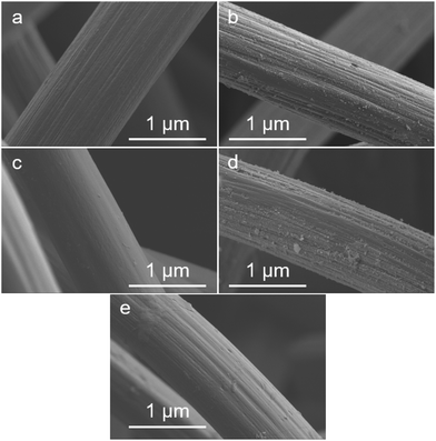 | ||
| Fig. 5 SEM images of Pristine (a), aged real negative (b), artificially aged negative (c), aged real reactivated negative (d), and aged artificial re-activated (e). | ||
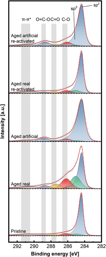
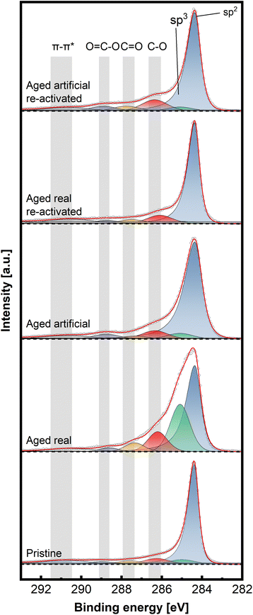
To gain insight into the chemical structure of the electrodes, XPS measurements were conducted. This method enables a better understanding of the carbon structures present before and after de/reactivation of the electrode materials. Fig. 6 and 7 display C 1s high-resolution spectra of the anode and cathode materials, respectively, whereby a comparison with pristine thermally activated felt was carried out for both sides. For deconvoluting the C 1s spectra, seven different peak contributions can be distinguished in all samples. The peaks were attributed to sp2 and sp3 hybridized carbon at ∼284.4 eV and ∼285 eV, hydroxyl and ether groups at ∼286.3 eV, carbonyls at ∼287.5eV, carboxyl at ∼289.0 eV and π–π* shake-up satellite at 290.5–293 eV.22–24 The individual percentage share of the respective components to the area integral is displayed for each spectrum in Table 2.
| sp2 | sp3 | C–O | C![[double bond, length as m-dash]](https://www.rsc.org/images/entities/char_e001.gif) O O |
O![[double bond, length as m-dash]](https://www.rsc.org/images/entities/char_e001.gif) C–O C–O |
π–π* | |
|---|---|---|---|---|---|---|
| Pristine | 66.45 | 5.99 | 7.39 | 4.42 | 3.34 | 12.41 |
| Cathode | ||||||
| Aged real | 38.66 | 20.71 | 17.11 | 7.94 | 5.52 | 10.06 |
| Aged real re-activated | 60.93 | 8.20 | 8.06 | 5.10 | 4.17 | 13.53 |
| Aged artificial | 77.62 | 2.27 | 5.39 | 1.85 | 7.63 | 5.24 |
| Aged artificial re-activated | 65.49 | 2.83 | 8.65 | 4.09 | 9.11 | 9.83 |
| Anode | ||||||
| Aged real | 46.60 | 29.43 | 11.50 | 4.92 | 2.52 | 5.03 |
| Aged real re-activated | 65.98 | 2.35 | 9.56 | 4.69 | 3.75 | 13.67 |
| Aged artificial | 73.34 | 4.99 | 7.41 | 2.61 | 4.31 | 7.34 |
| Aged artificial re-activated | 66.15 | 3.95 | 11.21 | 4.85 | 4.95 | 8.89 |
For the anodic side (Fig. 6), it can be observed that the real aged felt has an increased number of oxygen groups on the surface, while it is slightly reduced for the artificially aged sample (18.94% and 14.33% for real aged and artificially aged vs. 15.15% for pristine, all C–O contributions combined). This is accompanied by an increased proportion of sp3 carbon for the real aged samples and a slight decrease for artificially aged samples (29.43% and 4.99% for real aged and artificial aged vs. 5.99% for pristine). After reactivation, the C–O contributions for the reactivated real aged sample slightly decrease to 18% but increase for the reactivated artificially aged sample to 21.01%. The sp3 share is minimized significantly, to 2.35% and 3.95% for “reactivated real” and “reactivated artificial” respectively. It can therefore be concluded the reactivation leads to the removal of most sp3 carbon species from the surface, while the oxygen functionalities are not significantly altered during the reactivation. It must be remarked that the reactivation process is performed under air at elevated temperatures (793 K), where it is often suggested that such conditions could induce more severe surface oxidation processes. This is only partially found for the reactivated artificially aged sample (with a slight increase in C–O functionalities). For the reactivated real aged samples, the C–O functionalities even decrease. For the anode, a deactivation mechanism can be imagined that includes mainly the formation of sp3 carbons functionalities. Reactivation at elevated temperatures, remove those functionalized carbons (by decarboxylation/CO2 formation) and reinstates a graphitic environment high in sp2 carbons, while at the same time the amount of C–O functionalities stays in total rather constant.
On the cathodic side (Fig. 7), however, only the sample aged in real time shows a significant increase in C–O bonds (32.4% combined vs. 18.9% artificially aged and 15.9% pristine). The sp3 contribution is also mainly increased for the real-world aging (33.8% vs. 15.1% artificially aged and 12.3% pristine) Here, as well, the reactivation causes a removal of O-groups and reduction of sp3 content (18.8% combined C–O and 10.7% sp3 content for reactivated real aged), while the artificially aged felts before and after reactivation show similar characteristics to the pristine electrode (23.3% combined C–O and 11.5% sp3 content for reactivated artificially aged).
Combining all structural analysis results, the deactivation behaviour of negative electrodes correlates best with a reduction in carbon defects (D/G band ratio in Raman spectroscopy) and an increase in sp3 carbons and oxygen functionalities determined by XPS. The reactivation procedure greatly (but not completely) reverses these structural changes, especially concerning the D/G ratio, while the oxygen functionalities do not vary to a great extent. This indicates that the total number of oxygen functionalities, does not have a major influence on the electrochemical performance The sp2/sp3 ratio and the defect concentration seem to be of greater relevance. For positive electrodes the deactivation itself was not as pronounced compared to negative electrodes. However, the real word samples still showed an increased amount of oxygen and sp3 carbons, with the latter being removed after reactivation.
The artificially and real-world aged electrodes show a comparable electrochemical behaviour. Although, showing similar trends concerning structural changes during de- and reactivation, the changes in the artificially aged electrodes are often not as distinct as for the real-world samples.
Finally, the long-term electrochemical behaviour of all electrodes (pristine, aged and reactivated) was investigated. For this purpose, 120 CV cycles at 20 mV s−1 were performed and the resulting changes in peak currents and peak separations were observed (Fig. S16–18†). The pristine electrodes show a slight degradation over those 120 cycles, by a decrease in peak current and an increase in peak separation for the negative electrode. The oxidative current decreases from 58 mA to 52 mA and the reductive current from 60 mA to 56 mA, while the peak separation increases from 361 mV to 410 mV. On the positive electrode, the peak current increased minimally (from 53 to 58 for the oxidative peak and from 47 to 54 for the reductive peak) while the peak separation increased as well from 499 to 640 mV. The aged samples show only minor changes (regardless of real-world or artificially aged) and as already shown in Fig. 1 and 2, the initial lower peak current and greater separation indicate the undergone deactivation. It should be remarked that the peak current for the positive electrodes is, however, slightly increasing (for the reductive peak from 30 mA to 36 mA real-world and from 46 to 47 mA artificially aged), similar to the pristine samples. When investigating finally, the reactivated samples (from real-world and artificial aging), very similar electrochemical characteristics to pristine samples are found (as already described in Fig. 1 and 2). Also, the deactivation behaviour is similar to pristine samples, and no major changes in peak current or separation are observed for the reactivated electrodes (as cathode or anode).
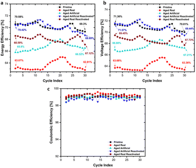
In addition to the CV tests, charge/discharge cycling tests in flow cells were conducted to investigate the materials under realistic VRFB application conditions. Key performance parameters such as energy efficiency, voltage efficiency and columbic efficiency are shown in Fig. 8 for all materials. The highest initial energy efficiency (Fig. 8a) was found for the pristine samples, which decreased from 70.58% to 69.3% during cycling. The initial energy efficiency of the real aged sample was with 63.07% significantly lower, and further declined to 62.81% after 30 cycles. The artificially aged sample showed a similar pattern, starting from 65.8% however, no gradual decrease but a slight improvement to 66.52% was found. Generally, the efficiency changes were rather minor. After reactivation of the real and artificially aged samples, both show a significant recovery of the efficiency, with the reactivated artificially aged samples reaching an energy efficiency of 70.42%, which is slightly declining to 68.69% during the cycling. The reactivated real aged sample shows a recovery to 68.59% initial efficiency, which is decreasing to 67.12% during the cycling. These results confirm the activity trend demonstrated in the cyclovoltammetry and EIS experiments, with the pristine sample showing the best performance, and a clear beneficial effect for the reactivation of the aged samples.
The same trends are found for the voltage efficiency (Fig. 8b) as well (Pristine: 71.36% to 70.01%, Real aged: 63.68% to 63.36%, Artificially aged: 66.88% to 67.21%, Reactivated real aged: 69.45% to 67.43%, Reactivated artificially aged: 71.54% to 69.44%). As shown in Fig. 8c, the coulombic efficiency remains stable, maintaining values over 98%, for all felt types.
These findings indicate that the reactivated electrodes do not only possess similar initial electrochemical performance, compared to pristine electrodes, but also their long-term performance is comparable. This is of great relevance for the lifetime extension of VRFB systems, as it can be expected that reactivated or recycled carbon electrodes, can deliver a similar performance as new electrode materials (thereby significantly enhancing the overall lifetime of VRFBs).
Conclusions
The degradation mechanism along with the reactivation of artificially aged and real aged carbon felts from a field-operated VRFB system was studied in detail. Electrochemical characterization along with surface analysis techniques were performed to analyse the carbon felts. Degradation behaviour was found for both electrodes, although it was significantly more pronounced for the negative electrode, as confirmed by electrochemical and EIS investigations. Detailed structural characterization with Raman spectroscopy and XPS showed that the deactivation of the negative electrode was accompanied by loss of defects and increased amounts of sp3 carbon and oxygen functionalities. The loss of defects was not as pronounced on the positive side, although the rise in sp3 carbons and oxygen functionalities was still observed. Thermal reactivation treatment of the felts can restore the structural composition of the electrodes, and significantly improve the electrochemical electrode performance. This finding was especially pronounced for the negative electrodes. The restored electrochemical activity correlated closely with the structural changes in the electrodes, meaning a close structural resemblance (especially concerning defects and sp2/sp3 carbon ratio) of reactivated electrodes with pristine ones, resulted in similar electrochemical behaviour. This allowed greater mechanistic insight into the degradation processes, and it can be concluded that loss of carbon defect sites by concomitant formation of sp3-carbon species is highly detrimental to the electrochemical performance of anodes in VRFBs. Even more relevant is, however, that a simple thermal reactivation process can reverse these deactivation processes greatly and reinstate electrochemical activity. Applying this simple procedure in real-world VRFB systems can significantly increase the lifetime of the systems or enable a suitable recycling pathway for carbon electrodes (which are currently not recycled).Author contributions
C. M. P and M. V. conceptualized and supervised this work. M. A. A., S. D., M. K. and M. O. performed electrochemical experiments and structural analysis. S. G. performed XPS measurements. M. A. A., S. D., M. K. and C. M. P. wrote the manuscript. All authors participated in discussions and corrections of the manuscript. FFG funding Project no 884672 for S. G. is gratefully acknowledged. We thank the AIC group at TU Wien for supporting XPS measurements.Conflicts of interest
There are no conflicts to declare.Acknowledgements
Financial support of “Gesellschaft fuer Forschungsfoerderung NOE” for M. K. and M. A. A. (FTI21 – D30 and D32) and the FFG COMET funding scheme (Competence Centers for Excellent Technologies by BMVIT, BMDW as well as the Province of Lower Austria and Upper Austria) is gratefully acknowledged. Enerox GmbH is gratefully acknowledged for supporting this work.References
- J. Hwang, B. M. Kim, J. Moon, A. Mehmood and H. Y. Ha, J. Mater. Chem. A, 2018, 6, 4695–4705 RSC.
- Q. Huang and Q. Wang, ChemPlusChem, 2015, 80, 312–322 CrossRef CAS.
- B. Dunn, H. Kamath and J. M. Tarascon, Science, 2011, 334, 928–935 CrossRef CAS PubMed.
- T. D. Nguyen, A. Whitehead, G. G. Scherer, N. Wai, M. O. Oo, A. Bhattarai, G. P. Chandra and Z. J. Xu, J. Power Sources, 2016, 334, 94–103 CrossRef CAS.
- I. Derr, M. Bruns, J. Langner, A. Fetyan, J. Melke and C. Roth, J. Power Sources, 2016, 325, 351–359 CrossRef CAS.
- G. L. Soloveichik, Chem. Rev., 2015, 115, 11533–11558 CrossRef CAS PubMed.
- A. Z. Weber, M. M. Mench, J. P. Meyers, P. N. Ross, J. T. Gostick and Q. Liu, J. Appl. Electrochem., 2011, 41, 1137–1164 CrossRef CAS.
- J. Langner, M. Bruns, D. Dixon, A. Nefedov, C. Wöll, F. Scheiba, H. Ehrenberg, C. Roth and J. Melke, J. Power Sources, 2016, 321, 210–218 CrossRef CAS.
- J. Melke, P. Jakes, J. Langner, L. Riekehr, U. Kunz, Z. Zhao-Karger, A. Nefedov, H. Sezen, C. Wöll, H. Ehrenberg and C. Roth, Carbon, 2014, 78, 220–230 CrossRef CAS.
- B. Sun and M. Skyllas-Kazacos, Electrochim. Acta, 1992, 37, 1253–1260 CrossRef CAS.
- B. Sun and M. Skyllas-Kazacos, Electrochim. Acta, 1992, 37, 2459–2465 CrossRef CAS.
- A. A. Shah, M. J. Watt-Smith and F. C. Walsh, Electrochim. Acta, 2008, 53, 8087–8100 CrossRef CAS.
- H. S. Choo, T. Kinumoto, M. Nose, K. Miyazaki, T. Abe and Z. Ogumi, J. Power Sources, 2008, 185, 740–746 CrossRef CAS.
- J. G. Oh, W. H. Lee and H. Kim, Int. J. Hydrogen Energy, 2012, 37, 2455–2461 CrossRef CAS.
- O. Nibel, S. M. Taylor, A. Pătru, E. Fabbri, L. Gubler and T. J. Schmidt, J. Electrochem. Soc., 2017, 164, A1608–A1615 CrossRef CAS.
- R. M. Bachman, D. M. Hall and L. R. Radovic, Carbon, 2023, 201, 891–899 CrossRef CAS.
- A. Bourke, M. A. Miller, R. P. Lynch, J. S. Wainright, R. F. Savinell and D. N. Buckley, ECS Trans., 2015, 66, 181–211 CrossRef CAS.
- P. Mazur, J. Mrlik, J. Pocedic, J. Vrana, J. Dundalek, J. Kosek and T. Bystron, J. Power Sources, 2019, 414, 354–365 CrossRef CAS.
- A. K. Singh, M. Pahlevaninezhad, N. Yasri and E. P. L. Roberts, ChemSusChem, 2021, 14, 2100–2111 CrossRef CAS PubMed.
- I. Derr, A. Fetyan, K. Schutjajew and C. Roth, Electrochim. Acta, 2017, 224, 9–16 CrossRef CAS.
- K. Köble, M. Jaugstetter, M. Schilling, M. Braig, T. Diemant, K. Tschulik and R. Zeis, J. Power Sources, 2023, 569, 233010 CrossRef.
- M. Schilling, L. Eifert, K. Köble, M. Jaugstetter, N. Bevilacqua, K. F. Fahy, K. Tschulik, A. Bazylak and R. Zeis, ChemSusChem DOI:10.1002/cssc.202301063.
- G. Wei, X. Fan, J. Liu and C. Yan, J. Power Sources, 2015, 281, 1–6 CrossRef CAS.
- C. Choi, H. Noh, S. Kim, R. Kim, J. Lee, J. Heo and H.-T. Kim, J Energy Storage, 2019, 21, 321–327 CrossRef.
- B. Sun and M. Skyllas-Kazacos, Electrochim. Acta, 1992, 37, 1253–1260 CrossRef CAS.
- M. Rychcik and M. Skyllas-Kazacos, J. Power Sources, 1988, 22, 59–67 CrossRef CAS.
- J. Saupsor, J. Sangsawang, W. Kao-ian, F. Mahlendorf, A. A. Mohamad, R. Cheacharoen, S. Kheawhom and A. Somwangthanaroj, Sci. Rep., 2022, 12, 1–12 CrossRef PubMed.
- I. Derr, M. Bruns, J. Langner, A. Fetyan, J. Melke and C. Roth, J. Power Sources, 2016, 325, 351–359 CrossRef CAS.
- A. Fetyan, G. A. El-Nagar, I. Lauermann, M. Schnucklake, J. Schneider and C. Roth, J. Energy Chem., 2019, 32, 57–62 CrossRef.
- H. Radinger, A. Ghamlouche, H. Ehrenberg and F. Scheiba, J. Mater. Chem. A, 2021, 9, 18280–18293 RSC.
- K. Köble, M. Jaugstetter, M. Schilling, M. Braig, T. Diemant, K. Tschulik and R. Zeis, J. Power Sources, 2023, 569, 233010 CrossRef.
- H. Radinger, V. Trouillet, F. Bauer and F. Scheiba, ACS Catal., 2022, 12, 6007–6015 CrossRef CAS.
- M. A. Pimenta, G. Dresselhaus, M. S. Dresselhaus, L. G. Cançado, A. Jorio and R. Saito, Phys. Chem. Chem. Phys., 2007, 9, 1276–1291 RSC.
- A. Das, S. Pisana, B. Chakraborty, S. Piscanec, S. K. Saha, U. V. Waghmare, K. S. Novoselov, H. R. Krishnamurthy, A. K. Geim, A. C. Ferrari and A. K. Sood, Nat. Nanotechnol., 2008, 3, 210–215 CrossRef CAS PubMed.
- T. J. Rabbow, M. Trampert, P. Pokorny, P. Binder and A. H. Whitehead, Electrochim. Acta, 2015, 173, 24–30 CrossRef CAS.
- H. Agarwal, J. Florian, D. Pert, B. R. Goldsmith and N. Singh, ACS Catal., 2023, 13, 2223–2233 CrossRef CAS.
- C. Choi, H. Noh, S. Kim, R. Kim, J. Lee, J. Heo and H.-T. Kim, J. Energy Storage, 2019, 21, 321–327 CrossRef.
- J. Lee, J. T. Muya, H. Chung and J. Chang, ACS Appl. Mater. Interfaces, 2019, 11, 42066–42077 CrossRef CAS PubMed.
- Z. Jiang and V. Alexandrov, ACS Appl. Energy Mater., 2020, 3, 7543–7549 CrossRef CAS.
- Y. Li, J. Parrondo, S. Sankarasubramanian and V. Ramani, J. Phys. Chem. C, 2019, 123, 6370–6378 CrossRef CAS.
- N. Pour, D. G. Kwabi, T. Carney, R. M. Darling, M. L. Perry and Y. Shao-Horn, J. Phys. Chem. C, 2015, 119, 5311–5318 CrossRef CAS.
Footnotes |
| † Electronic supplementary information (ESI) available. See DOI: https://doi.org/10.1039/d3nr06300c |
| ‡ These authors contributed equally to this work. |
| This journal is © The Royal Society of Chemistry 2024 |


