
 Open Access Article
 This Open Access Article is licensed under a Creative Commons Attribution-Non Commercial 3.0 Unported Licence
Tuning the performance of Fe–porphyrin aerogel-based PGM-free oxygen reduction reaction catalysts in proton exchange membrane fuel cells
Yeela
Persky
,
Yan
Yurko
,
Rifael Z.
Snitkoff-Sol
,
Noam
Zion
and
Lior
Elbaz
 *
*
Chemistry Department, Bar-Ilan Center for Nanotechnology and Advanced Materials, Bar-Ilan University, Ramat-Gan 5290002, Israel. E-mail: lior.elbaz@biu.ac.il
First published on 12th December 2023
Abstract
Fe–N–C catalysts are currently the leading candidates to replace Pt-based catalysts for the oxygen reduction reaction in proton exchange membrane fuel cells. To maximize their activity, it is necessary to optimize their structure to allow high active site density on one hand, and hierarchical porous structure that will allow good mass transport of reactants and products to and from the active sites on the other hand. Hence, the hierarchical structure of the catalyst plays an important role in the balance between the electrochemical active site density and the mass transport resistance. Aerogels were synthesized in this work to study the interplay between these two parameters. Aerogels are covalent organic frameworks with ultra-low density, high porosity, and large surface area. The relative ease of tuning the composition and pore structure of aerogels make them prominent candidates for catalysis. Herein, we report on a tunable Fe–N–C catalyst based on an Fe porphyrin aerogel, which shows high electrocatalytic oxygen reduction reaction activity with tunable hierarchical pore structure and studied the influence of the porous structure on the overall performance in proton exchange membrane fuel cells.
Introduction
At the heart of the transition to a hydrogen economy, fuel cells play a pivotal role,1 but their price and durability still need to be improved.2–7The oxygen reduction reaction (ORR) is regarded as the bottleneck reaction in proton exchange membrane fuel cell (PEMFC) technologies,8 and strongly affects their overall performance and efficiency.9 Hence, fuel cells’ research in the past decade has mainly been focused on the search for new ORR catalysts based on Earth-abundant, non-critical, and thus cheap, materials.10,11 One of the most interesting categories of platinum group metal-free (PGM-free) ORR catalysts comprises bio-inspired catalysts,12 composed of macrocyclic complexes of transition metals, such as metallo-porphyrins and other macrocyclic complexes.13–16 A sub-category that evolved from this work is the MNC catalyst composed of a transition metal (usually Fe), a nitrogen source to coordinate the Fe ions, and a carbon source to serve as the framework for this catalytic system.17 The performance of these PGM-free catalysts is relatively high in terms of electrochemical cell measurements but does not necessarily transfer well to fuel cell performance for several reasons such as low electrochemically active site density,18–20 formation of peroxides, overall durability and stability under electrochemical and chemical environments in fuel cells,21,22 and mass-transport issues.23 Hence, further improvements are necessary in order to realize their full potential and make fuel cell technologies more viable alternatives for green energy generation.
One possible way to circumvent some of these issues is to increase the electrochemically active site density.20,24 A promising path to achieve this, is by using highly porous materials with maximal active site density.25,26 One such family of materials are aerogels.26–28 Aerogels are composed of a network of covalently bonded molecules that form a ultra-low density, highly porous, hierarchical, covalent framework.29,30 Previous studies used an iron porphyrin as a monomer and an aldehyde cross-linker to form a porphyrin aerogel with ultra-high mass site density (MSD).31,32 In order to achieve optimal performance, utilize the maximum number of active sites, and reach high electrochemically active site density (EASD), one must consider the tradeoff between the EASD and the control of the hierarchical structure of the aerogel and its pore size distribution, which can be tuned to allow optimal mass transport to and from the active sites and expose a significant portion of them.33 Understanding the tradeoff between these parameters can provide useful distinctions regarding PGM-free catalysts in general, and aerogel-based PGM-free ORR catalysts in particular. The selected aerogel systems can be used as good model systems since they are composed of a well-defined atomically dispersed catalyst.
Herein, the length of the aerogel cross-linker molecule was changed in order to study the interplay between the EASD and mass transport. This change entails several differences between the aerogel structures. These new aerogels were studied in PEMFCs and optimized for best performance.
Results and discussion
Iron porphyrin aerogels were synthesized in this work according to a known recipe,32 but with one significant change, namely that different lengths of linker molecules were used in order to increase the pore size in the cavities of the aerogel. The full detailed description of the aerogels’ synthesis is given in the Experimental methods section. The aerogels’ cross-linkers differ from each other in their number of aromatic rings and are expected to form structural differences between the aerogels, mainly in the pore size distribution, which will translate into differences in the mass transport resistance in PEMFCs. The cross-linkers and the corresponding aerogels’ names (named after the cross-linker, i.e., 1-FePA for 1 benzene ring in an Fe porphyrin aerogel, 2-FePA for two benzene rings, etc.) are presented in Scheme 1.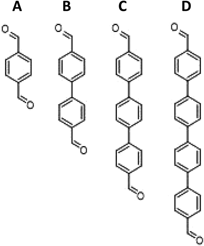 | ||
| Scheme 1 Different cross-linkers used for synthesizing Fe-porphyrin aerogels: (A) terephthalaldehyde (1-FePA), (B) 4,4′-biphenyldicarboxaldehyde (2-FePA), (C) [1,1′:4′,1′′-terphenyl]-4,4′′-dicarboxaldehyde (3-FePA), and (D) [1,1′:4′,1′′:4′′,1′′′-quarterphenyl]-4,4′′′-dicarbaldehyde (4-FePA). | ||
The morphology of the aerogels was studied using SEM. As can be seen from the images in Fig. 1, the structures of the four aerogels in Scheme 1 are quite different. This is the first indication that the cross-linkers have significant impact on the aerogel structure. The 1-FePA seems to be composed of aggregates of interconnected nanoparticles that build the aerogel, whereas the 2-FePA forms bulky interconnected balls, which resemble cotton balls with large void volumes between them. The 3-FePA seems to resemble the 2-FePA, but is decorated by some wires and flakes, while the 4-FePA seems to have formed dense nanosheets of the porphyrin aerogel.
 | ||
| Fig. 1 SEM images of (A) 1-FePA, (B) 2-FePA, (C) 3-FePA, and (D) 4-FePA. | ||
Rotating ring-disk electrode (RRDE) measurements were conducted both in acidic (0.5 M H2SO4) and alkaline (0.1 M KOH) electrolytes to study the electrocatalytic activity of all four aerogels (Fig. 2). In both electrolytes, the 2-FePA reached the highest limiting current density, indicative of its tendency for higher reaction selectivity for the 4e− (or 2 + 2) reduction to water, when compared to the other aerogels. 4-FePA and 3-FePA exhibit the lowest and the highest onset potentials and half-wave potentials, respectively, which indicate the lowest and highest reaction kinetics as well. These aerogels also reached the lowest limiting current density, which indicates lower selectivity toward 4e− reduction to water and higher peroxides production, according to the Levich equation. The increased distance between the active sites in 3-FePA and 4-FePA might decrease the synergistic effect between adjacent sites and therefore resulted in lower selectivity toward 4e− reduction. All the onset and half-wave potentials, as well as the limiting currents of each measurement, are summarized in Table 1. It is very apparent that all aerogels perform better under alkaline conditions than in acidic electrolyte, with almost 100 mV difference in onset and half-wave potentials, and higher selectivity for the 4e− (or 2 + 2e−) ORR mechanism.
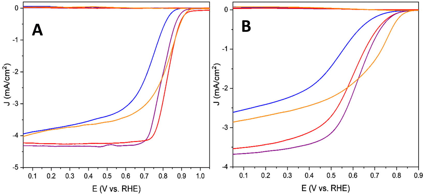 | ||
| Fig. 2 RRDE measurements (O2-saturated, 900 rpm, 5 mV s−1) in (A) 0.1 M KOH and (B) 0.5 M H2SO4 of 1-FePA (red), 2-FePA (purple), 3-FePA (orange), and 4-FePA (blue). | ||
| Cross-linker | In alkaline electrolyte (0.1 M KOH) | In acidic electrolyte (0.5 M H2SO4) | ||||
|---|---|---|---|---|---|---|
| E onset (V vs. RHE) | E 1/2 (V vs. RHE) | Number of electrons | E onset (V vs. RHE) | E 1/2 (V vs. RHE) | Number of electrons | |
| 1-FePA | 0.95 | 0.84 | 3.9 | 0.874 | 0.601 | 3.3 |
| 2-FePA | 0.957 | 0.795 | 4.0 | 0.858 | 0.623 | 3.6 |
| 3-FePA | 0.957 | 0.816 | 3.5 | 0.874 | 0.699 | 2.6 |
| 4-FePA | 0.905 | 0.750 | 3.4 | 0.849 | 0.542 | 2.3 |
Stability tests were performed in alkaline (0.1 M KOH) electrolytes (Fig. 3). All the aerogels showed very good stability for the duration of the experiments (12 hours), with 1-FePA and 4-FePA exhibiting the highest and lowest stability, respectively. The 1-FePA lost less than 5% of its initial current density during a potentiostatic measurement at 0.5 V vs. RHE, whereas the 4-FePA lost about 12% of its performance. The differences between the stability of these aerogels can be attributed to the less selective 4-electron ORR with the 4-FePA and the formation of peroxide anions at higher concentrations, as can be deduced from Table 1.
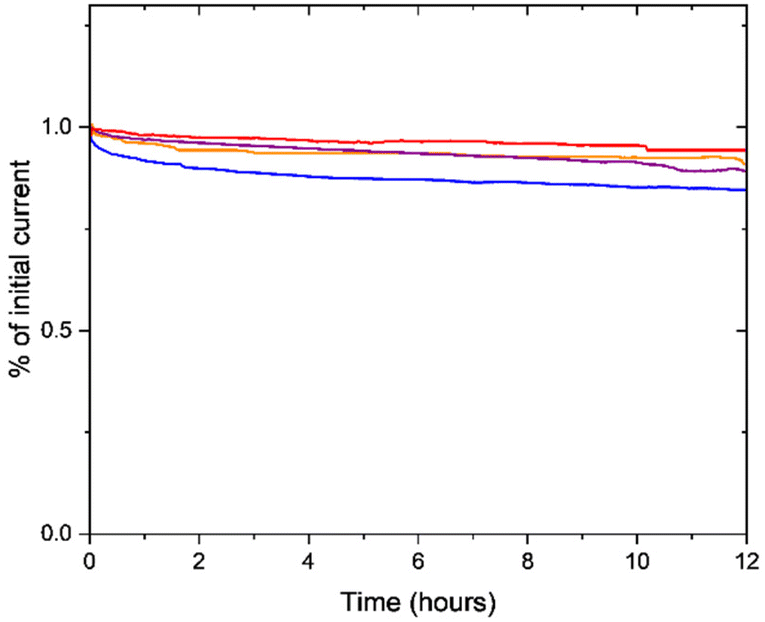 | ||
| Fig. 3 Stability measurements at 0.5 V vs. RHE in 0.1 M KOH (O2-saturated, 200 rpm) of 1-FePA (red), 2-FePA (purple), 3-FePA (orange), and 4-FePA (blue). | ||
N2 adsorption isotherm measurements were performed in order to gain insight into the porous nature of the various aerogels and understand how the size of the linker molecule affects it. The calculated BET surface areas of all four aerogels are presented in Table 2. As can be seen in this table, the surface area increases with the increase in the length of the linker up until the length of the third aromatic ring. The increase in the size of the linker can be expected to result in larger pores, and thus larger total void volumes, given the fact that the same amount of porphyrin was used in the synthesis of all aerogels, and thus also in an increase in the surface area. The 4-FePA is an exception, most probably due to the collapse of some of the pores and formation of a dense aerogel, as was also observed in the SEM image, where it formed dense nano-flakes.
| Cross-linker | 1-FePA | 2-FePA | 3-FePA | 4-FePA |
|---|---|---|---|---|
| Surface area (m2 g−1) | 249.17 | 361.96 | 412.01 | 377.07 |
The pore size distribution of the aerogels was also studied to further understand the differences between them. As mentioned earlier, the size of the pores may affect the mass transport and the EASD, and thus an optimum balance between the MSD, the EASD and mass transport should be found to maximize the performance of aerogels in fuel cells. Generally, micropores increase the surface area, mesopores promote wetting inside the pores, and thus increase the EASD, and create the three-phase boundary between the catalyst, the electrolyte, and the oxygen, while macropores help facilitate the mass transport into the pores.34–36 A combination of all of the above, to create a tunable hierarchical structure, is expected to result in high electrocatalytic performance, especially in fuel cells.
The pore size distributions of all four aerogels are presented in Fig. 4A and B. The pore size distributions were normalized according to the surface area of the pores in order to understand the different ratios between the pore sizes for each aerogel. As can be seen in Fig. 4B, each aerogel has different pore size distributions. The 2-FePA structure has more meso- and macro-pores in comparison with the micro-pores than the other aerogels. The majority of 3-FePA's surface area comes from 2 pore sizes: below 1 nm and around 3.8 nm, and it almost does not have any meso-pores, whereas the 4-FePA is composed mostly of micro-pores below 1 nm (61%), which confirms the previous observations regarding its density. The 1-FePA is also mostly composed of micro-pores, but unlike 4-FePA, the rest of its surface area is composed of a wider range of pore sizes, which indicates a more hierarchical structure in the 1-FePA aerogel. An indication for the existence of large macro-pore in these aerogels can be obtained from their N2 adsorption–desorption isotherms, which are presented in Fig. 4C. This is manifested by the rapid increase in the adsorption at P/P0 close to 1, which is associated with pore condensates in macro-pores,37,38 and suggests the existence of macro-pores in all the aerogels, as was also observed clearly in the SEM images, with 3-FePA having the largest portion of macro-pores, and 4-FePA having the lowest. This analysis suggests that 2-FePA has the most hierarchical pore structure of the aerogels studied in this work.
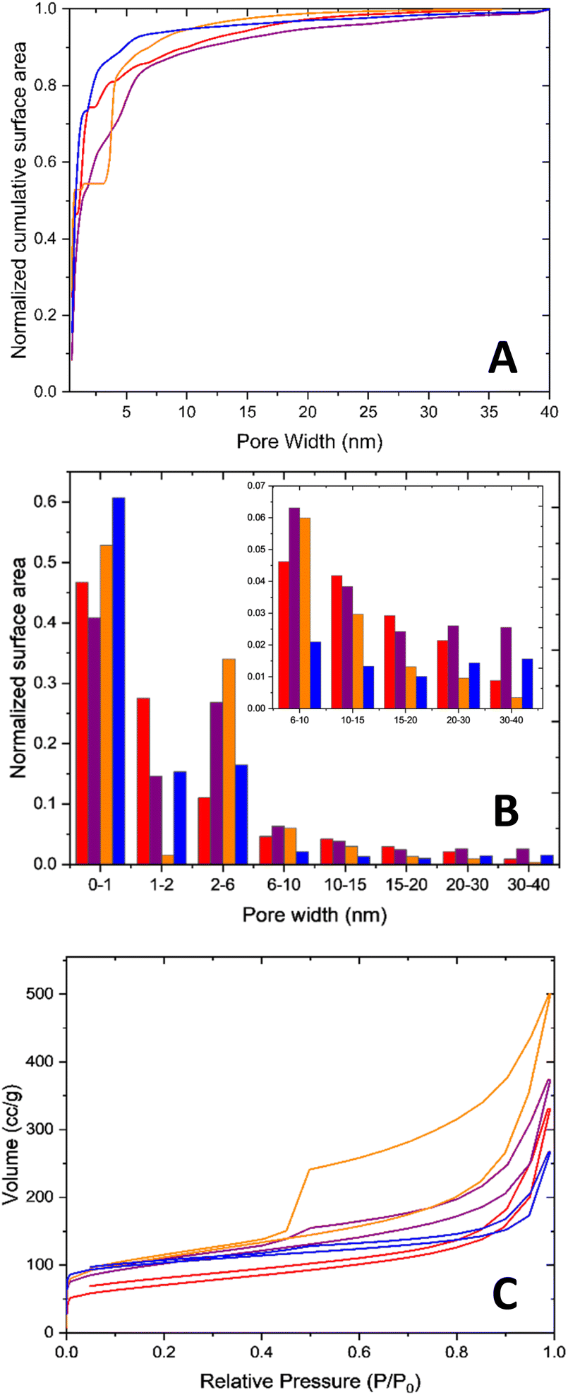 | ||
| Fig. 4 (A) The cumulative surface area, normalized according to the DFT surface area, (B) the normalized pore size distribution, and (C) N2 adsorption–desorption isotherm. 1-FePA (red), 2-FePA (purple), 3-FePA (orange), and 4-FePA (blue). | ||
Another important parameter that affects catalytic activity is the site density. Intuitively, increasing the length of the cross-linkers can cause a decrease in the mass site density (MSD), and this was confirmed by ICP measurements (Table 3) that show a decrease in the Fe content with an increase in the cross-linker length. An increase in the length of the cross-linker translates to an increase in the weight percentage of carbon and correspondingly a decrease in the iron weight percentage.
| Cross-linker | 1-FePA | 2-FePA | 3-FePA | 4-FePA |
|---|---|---|---|---|
| ICP Fe (wt%) | 7.52 | 6.99 | 6.06 | 6.12 |
Although the MSD is important, measuring the EASD is the accurate way to report the active site density, since it takes into account only the electrochemically accessible sites, or in simpler words, only those sites that are available to participate in the reaction. To calculate the EASD in a working fuel cell, cyclic voltammetry (CV) measurements were performed in proton exchange membrane fuel cells (PEMFCs) (Fig. 5). The CVs of all the aerogels have a similar peak at around 0.76 V vs. the H2 anode, which is associated with redox peaks of Fe(III)/(II).19,39,40 Since the active sites of this category of PGM-free catalysts are known to be FeN4,41,42 and the catalytic cycle involves the redox reaction of the Fe(III)/(II) couple,43 the integration of the area under the peaks can be used to calculate the EASD. This is not always so clear and easy, and in most cases, more advanced electrochemical techniques, such as Fourier-transformed alternating current voltammetry, are required if the peaks are not well pronounced in the CV.19,20 The EASD was calculated using eqn (1):44
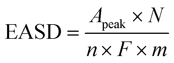 | (1) |
![[thin space (1/6-em)]](https://www.rsc.org/images/entities/char_2009.gif) 485 C mol−1) and m is the catalyst loading (g). The results are presented in Table 4.
485 C mol−1) and m is the catalyst loading (g). The results are presented in Table 4.
 | ||
| Fig. 5 Cyclic voltammetry measurement in fuel cells. Anode/cathode, H2/N2, 200 ccm/800 ccm, 80 °C/80 °C/80 °C. 1-FePA (red), 2-FePA (purple), 3-FePA (orange), and 4-FePA (blue). | ||
| Cross-linker | 1-FePA | 2-FePA | 3-FePA | 4-FePA |
|---|---|---|---|---|
| Peak area (mC cm−2) | 13.45 | 27.64 | 27.90 | 26.05 |
| EASD (sites × 1019 g−1) | 2.09 | 4.64 | 4.13 | 4.46 |
All four aerogels showed very similar EASD values, except for the 1-FePA, which showed a lower EASD, although according to the ICP results (Table 3), this aerogel has the highest Fe wt%. This can be explained by the formation of hidden Fe sites as discussed earlier.
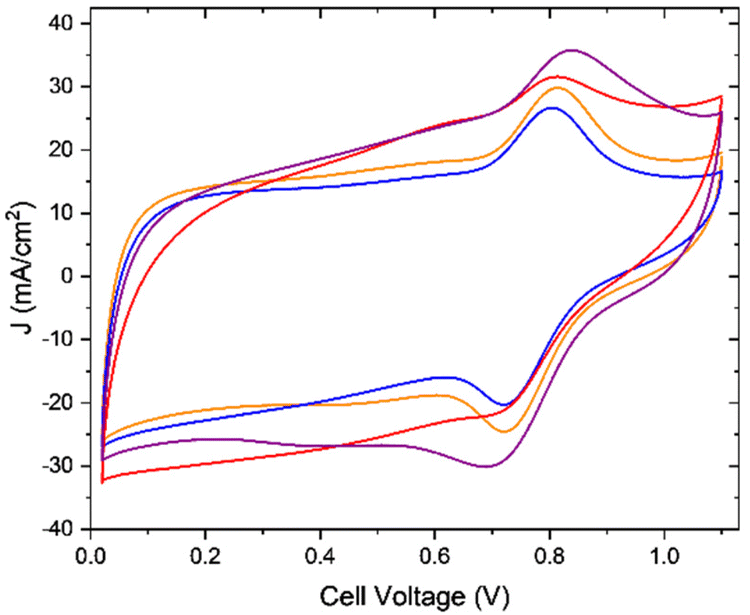
The ultimate way to study the effect of the aerogels' hierarchical structure, which seems to be the most significant difference between the aerogels based on the EASD and BET measurements, is the fuel cell measurement. And thus, in order to acquire a more comprehensive picture of the performance of the aerogels as ORR electrocatalysts, which is not necessarily reflected in RRDE measurements,23 the aerogels were tested in an H2–air PEMFC (Fig. 6A and B). The results were compared to those of a Pajarito Powder cathode as well, which was outperformed by the 1-FePA and the 2-FePA. From the I–V curves of all four aerogels, the PEMFC based on 2-FePA as the cathode catalyst exhibited the highest current densities at both high potential and low potential. The open-circuit voltage (OCV) was very close between all four aerogels.
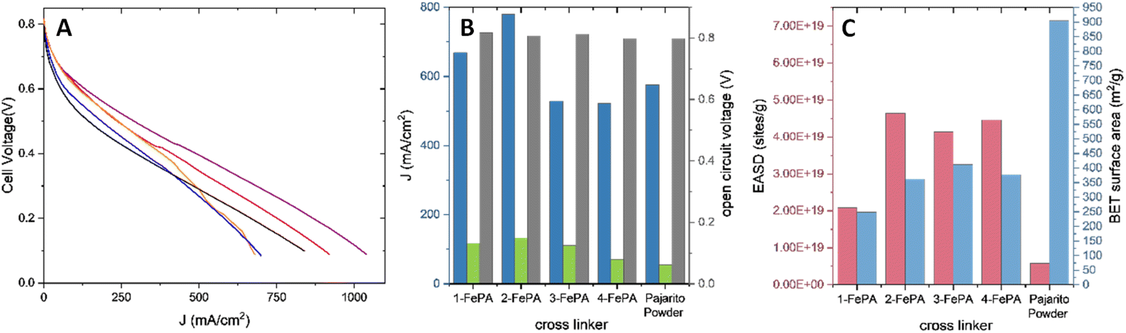 | ||
| Fig. 6 (A) Fuel cell measurements. H2/air, 200 ccm/200 ccm, 80 °C/80 °C/80 °C. 1-FePA (red), 2-FePA (purple), 3-FePA (orange), 4-FePA (blue), commercial Pajarito Powder (black). (B) PEMFC activity summary. J at 0.25 V (blue), J at 0.60 V (green) and OCV (gray). (C) Summary of the EASD (pink) and the BET surface area (azure) in comparison to the activity. | ||
The kinetic current densities were determined from the results shown in Fig. 6A at 0.75 V and are found to be Jk@0.75 V = 12.08, 13.00, 14.14, and 7.9 mA cm−2 for 1-FePA, 2-FePA, 3-FePA, and 4-FePA, respectively. These results in the kinetic activation region agree with the RRDE results (Fig. 2A and B), showing that the 3-FePA is the most active aerogel in this region but is not the overall best catalyst of the four, where from the RRDE measurements it seems to have much lower selectivity for the 4e− (or the consecutive 2 + 2) ORR mechanism, much like the 4-FePA, whereas the 1-FePA and the 2-FePA show better selectivity, both in alkaline and acidic environments, manifested in their higher current densities in RRDE and in higher current densities in the PEMFC polarization curves (Fig. 6A). This could be explained by the distance between active sites, which allows higher selectivity, and eventually higher overall performance in a fuel cell, as the active sites are closer together as was observed with molecular dual-site porphyrinic systems described in the past.45 This is an important indication for the synergistic behavior of these active sites.
The fuel cell performance does not correlate with the BET surface area, nor the EASD, as illustrated in Fig. 6B and C, but it does correlate with the pore size distributions of the aerogels, which might explain the trend in higher current densities. The highest activity was observed with the 2-FePA aerogel, which has the most hierarchical structure (Fig. 4A and B). 4-FePA, which is composed mostly of a large proportion of <1 nm pores, shows the lowest activity, whereas the 3-FePA, which is mainly composed of <1 nm and ∼3.8 nm pores, exhibits reasonable activity at high potentials, but relatively poor activity at lower potentials because of its non-hierarchical structure. 1-FePA, which also has a hierarchical structure, also reached relatively high activity in its PEMFC.
In order to test this hypothesis and to achieve better understanding of the influence of mass transport resistance on the activity, the aerogels were tested in a PEMFC with mixture of N2/O2, with 4% O2. The measurements were carried out in order to test the performance in a low-oxygen environment where the mass transport becomes critical. The I–V polarization curves are presented in Fig. 7.
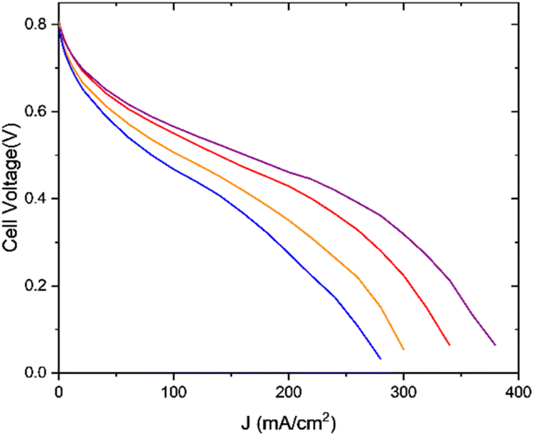 | ||
| Fig. 7 Fuel cell measurements. H2/96% Ar–4% O2, 200 ccm/200 ccm, 80 °C/80 °C/80 °C. 1-FePA (red), 2-FePA (purple), 3-FePA (orange), and 4-FePA (blue). | ||
In this case, the cell with the 2-FePA aerogel also exhibited the highest performance and reached the mass transport limitation at much higher current densities compared to the other aerogels. The “knee”, which represents the transition from the ohmic region to the mass transport region, started at lower current densities for the aerogels with lower hierarchy in their pore structure, and the performance trend increased according to the following order: 4-FePA < 3-FePA < 1-FePA < 2-FePA. These measurements confirm that the structure of an aerogel does indeed affect the mass transfer, and therefore optimized structure, with hierarchical pore structure, can be critical to obtaining high performance in PEMFCs with this class of catalysts.
Conclusions
In this work, we synthesized and studied Fe porphyrin aerogels with relatively easily tunable pore structures. The length of the cross-linker was simply changed in the synthesis of the aerogels, which led to many differences in the aerogels’ morphology, surface area, electrochemically active site density, and their porous structures. These changes entailed activity changes, mainly in the measurements of fuel cells. The optimized aerogel was found to be 2-FePA, with its 2 aromatic rings cross-linker. The 2-FePA showed the best activity as a result of its hierarchical pore structure, which promoted high site density, high surface wetting (manifested in its high EASD), and low mass transport resistance. The performance of the other aerogels supports the correlation between the activity and the pore structure. These findings will allow smarter material design that considers all material parameters, not just the surface area and the EASD (or the MSD), which do not necessarily correlate with the overall performance in fuel cells.Experimental methods
Synthesis
32 mg of FeCl2·4H2O (Acros-organics) was dissolved in 500 μl of dimethyl sulfoxide (DMSO). After the dissolution, 18 mg of free-base porphyrin, 5,10,15,20-(tetra-4-aminophenyl)porphyrin (PorphyChem), was added to the reaction vial. The solution was heated to 80 °C, while stirring, for half an hour. A 500 μl solution of cross-linker dissolved in DMSO, with a 1:2 molar ratio of porphyrin:cross-linker, was added dropwise to the porphyrin solution and was mixed for 40 seconds. The aerogels were polymerized via a condensation reaction between the porphyrin with its amino substituents and cross-linkers, aromatic molecules with aldehyde substituents. Different cross-linkers were used for each sample: (1) 1-FePA – terephthalaldehyde (Alfa Aesar), (2) 2-FePA – 4,4′-biphenyldicarboxaldehyde (Acros-organics), (3) 3-FePA – [1,1′:4′,1′′-terphenyl]-4,4′′-dicarboxaldehyde (ChemScene LLC) and (4) 4-FePA – [1,1′:4′,1′′:4′′,1′′′-quaterphenyl]-4,4′′′-dicarbaldehyde (ChemScene LLC). The mixed solution was heated to 80 °C overnight. Once the gel was formed, it was washed with DMSO to remove unreacted chemicals until the washing solution above the gel became colorless. Later, the gel was washed with acetone several times, to replace the solvent in the gel for super-critical drying, followed by a drying process using supercritical CO2 in a critical-point dryer (Leica EM CPD300 Auto). The obtained aerogel was subjected to a heat treatment process, carried out in a glass-tube oven (Thermo Scientific-Lindberg Blue M) under argon (150 sccm). The thermal process was chosen according to a previous study. The temperature was elevated from 25 °C to 200 °C for 20 minutes and held at 200 °C for 2 hours. Then the temperature was elevated from 200 °C to 800 °C for 5 hours (2 °C min−1) and held at 800 °C for two hours.
Characterization
Inductively coupled plasma (ICP) measurements were performed for Fe using a SPECTRO ARCOS ICP-OES, Multiview, FHX22 instrument. The sample was prepared by heat treating 2 mg of each sample under air at 500 °C for 20 hours, followed by Fe dissolution in concentrated HCl and diluting this with deionized water (DIW).The Brunauer–Emmett–Teller (BET) surface area measurements were conducted using an N2 adsorption isotherm at 77 K in Quantachrome Autosorb iQ. The pore size distribution was calculated according to DFT models.
The morphology was studied using an Environmental Scanning Electron Microscope (E-SEM, Quanta FEG 250).
Half-cell measurements
Rotating ring-disk electrode (RRDE) measurements were carried out using a Bio-Logic VMP 300 bipotentiostat. 2 mg of the aerogel was ground in a solution with ratio of 1:2 deionized water:isopropanol (volume ratio) with 0.2% Nafion, forming a 10 mg ml−1 slurry, followed by 1 hour of sonication. 10 μl of the slurry was deposited onto the glassy carbon disk of the RRDE electrode (Pine Instruments) in 2 portions of 5 μl each and dried at room temperature. The measurements were carried out in a three-electrode cell (Pine Instruments), with the glassy carbon as the working electrode, glassy carbon rod as the counter electrode, and RHE as the reference electrode. The acidic media measurements were performed in 0.5 M H2SO4 (95%–97%, Chem-Lab) and the alkaline measurements in 0.1 M KOH (Sigma-Aldrich).
MEA fabrication
The membrane electrode assemblies (MEAs) for fuel cell measurements were prepared in the laboratory. Commercial 20% Pt/C-22BB (fuel cells, etc.) was used as an anode. For reference, a cathode of Pajarito powder was made using PMF-012101 Pajarito powder. For the other cathodes, each aerogel was ground and mixed with 35.5% Nafion D2021 and 1:1 wt% deionized water:isopropanol. The slurry was sonicated for 1 hour and stirred overnight. Then, the slurry was diluted to an overall volume of 11.5 ml and sonicated for 1 more hour. The slurry was sprayed on a 5 cm2 BC-29 gas diffusion layer (GDL) up to a loading of 4 mg cm−2 using SonoTek Technologies (sonication nozzle at 48 kHz) followed by the deposition of a thin D2021 Nafion layer. Nafion membrane NR211 was used in the MEA. The MEA was hot pressed at 130 °C for 2 min under a force of 2000 pounds.
Fuel cell measurements
Fuel cell measurements were performed in an 850e Scribner Associates fuel cell test station. The cell was operated at 80 °C. H2 was made to flow in the anode at 80 °C, at a flow rate of 200 sccm and 100% RH. The cathode mixture was a combination of different amounts of O2 or air from the station and N2 at a total flow rate of 200 sccm (air: 100% air, 4% O2: 1:4 air:N2). The cathode was operated at 80 °C and 100% RH. Before making any measurements, a break-in process was performed, and the cell was held at 0.4 V for 30 min. After that, for each mixture, polarization curves were recorded. The cell was washed for 15 min at OCV with the same cathode mixture as used before the measurement. CVs in an N2 atmosphere were performed in 1 cm2 cells with the same preparation method, with an 800 sccm flow rate of N2 in the cathode.
Conflicts of interest
There are no conflicts to declare.Acknowledgements
This work was conducted in the framework of the Israeli Fuel Cells Consortium (IFCC) and was supported by the Israeli Ministry of Science and Technology, the Israeli Ministry of Energy, and the Israel Science Foundation. YP would like to thank The Israeli Smart Transportation Research Center (ISTRC) for (partially) funding her research. This research is also supported by the Israeli Ministry of Energy as part of the scholarships program for undergraduate and graduate students in the discipline of energy.References
- M. Conte, A. Iacobazzi, M. Ronchetti and R. Vellone, Hydrogen economy for a sustainable development: state-of-the-art and technological perspectives, J. Power Sources, 2001, 100, 171–187 CrossRef.
- P. Zegers, Fuel cell commercialization: The key to a hydrogen economy, J. Power Sources, 2006, 154, 497–502 CrossRef.
- A. Kozhushner, Q. Li and L. Elbaz, Heteroatom-Doped Carbon Supports with Enhanced Corrosion Resistance in Polymer Electrolyte Membrane Fuel Cells, Energies, 2023, 16, 3659 CrossRef.
- Y. Yurko and L. Elbaz, The effect of membrane electrode assembly methods on the performance in fuel cells, Electrochim. Acta, 2021, 389, 138676 CrossRef.
- C. B. Krishnamurthy, O. Lori, L. Elbaz and I. Grinberg, First-Principles Investigation of the Formation of Pt Nanorafts on a Mo2C Support and Their Catalytic Activity for Oxygen Reduction Reaction, J. Phys. Chem. Lett., 2018, 9, 2229–2234 CrossRef PubMed.
- O. Lori, S. Gonen and L. Elbaz, Highly Active, Corrosion-Resistant Cathode for Fuel Cells, Based on Platinum and Molybdenum Carbide, J. Electrochem. Soc., 2017, 164, F825–F830 CrossRef.
- K. J. Blackmore, L. Elbaz, E. Bauer, E. L. Brosha, K. More, T. M. McCleskey and A. K. Burrell, High Surface Area Molybdenum Nitride Support for Fuel Cell Electrodes, J. Electrochem. Soc., 2011, 158, B1255–B1259 CrossRef.
- S. Zaman, L. Huang, A. I. Douka, H. Yang, B. You and B. Y. Xia, Oxygen reduction electrocatalysts toward practical fuel cells: progress and perspectives, Angew. Chem., 2021, 133, 17976–17996 CrossRef.
- L. Yang, J. Shui, L. Du, Y. Shao, J. Liu, L. Dai and Z. Hu, Carbon–based metal–free ORR electrocatalysts for fuel cells: past, present, and future, Adv. Mater., 2019, 31, 1804799 CrossRef PubMed.
- U. Martinez, S. Komini Babu, E. F. Holby, H. T. Chung, X. Yin and P. Zelenay, Progress in the development of Fe–based PGM–free electrocatalysts for the oxygen reduction reaction, Adv. Mater., 2019, 31, 1806545 CrossRef PubMed.
- L. Elbaz, G. Wu and P. Zelenay, Heat-Treated Non-precious-Metal-Based Catalysts for Oxygen Reduction, in Electrocatalysis in Fuel Cells, ed. M. Shao, Lecture Notes in Energy, Springer, London, 2013, vol. 9, pp. 213–246 Search PubMed.
- N. Zion, A. Friedman, N. Levy and L. Elbaz, Bioinspired Electrocatalysis of Oxygen Reduction Reaction in Fuel Cells Using Molecular Catalysts, Adv. Mater., 2018, 30, e1800406 CrossRef PubMed.
- D. Grumelli, B. Wurster, S. Stepanow and K. Kern, Bio-inspired nanocatalysts for the oxygen reduction reaction, Nat. Commun., 2013, 4, 2904 CrossRef PubMed.
- N. Zion, A. Friedman, N. Levy and L. Elbaz, Bioinspired electrocatalysis of oxygen reduction reaction in fuel cells using molecular catalysts, Adv. Mater., 2018, 30, 1800406 CrossRef PubMed.
- A. Friedman, I. Saltsman, Z. Gross and L. Elbaz, Electropolymerization of PGM-free molecular catalyst for formation of 3D structures with high density of catalytic sites, Electrochim. Acta, 2019, 310, 13–19 CrossRef.
- M. Kosa, N. Levy, L. Elbaz and D. T. Major, Theoretical Study of the Electrocatalytic Reduction of Oxygen by Metallocorroles, J. Phys. Chem. C, 2018, 122, 17686–17694 CrossRef.
- A. Sarapuu, E. Kibena-Põldsepp, M. Borghei and K. Tammeveski, Electrocatalysis of oxygen reduction on heteroatom-doped nanocarbons and transition metal–nitrogen–carbon catalysts for alkaline membrane fuel cells, J. Mater. Chem. A, 2018, 6, 776–804 RSC.
- A. Kozhushner, N. Zion and L. Elbaz, Methods for Assessment and Measurement of the Active Site Density in PGM-free ORR Catalysts, Curr. Opin. Electrochem., 2020, 25, 100620 CrossRef.
- R. Z. Snitkoff-Sol, A. Friedman, H. C. Honig, Y. Yurko, A. Kozhushner, M. J. Zachman, P. Zelenay, A. M. Bond and L. Elbaz, Quantifying the electrochemical active site density of precious metal-free catalysts in situ in fuel cells, Nat. Catal., 2022, 5, 163–170 CrossRef.
- R. Z. Snitkoff-Sol and L. Elbaz, Assessing and measuring the active site density of PGM-free ORR catalysts, J. Solid State Electrochem., 2022, 26, 1839–1850 CrossRef.
- H. C. Honig and L. Elbaz, Degradation Mechanisms of Platinum Group Metal-Free Oxygen Reduction Reaction Catalyst based on Iron Phthalocyanine, ChemElectroChem, 2023, 10, e202300042 CrossRef.
- H. C. Honig, C. B. Krishnamurthy, I. Borge-Durán, M. Tasior, D. T. Gryko, I. Grinberg and L. Elbaz, Structural and Physical Parameters Controlling the Oxygen Reduction Reaction Selectivity with Carboxylic Acid-Substituted Cobalt Corroles Incorporated in a Porous Carbon Support, J. Phys. Chem. C, 2019, 123, 26351–26357 CrossRef.
- L. Du, V. Prabhakaran, X. Xie, S. Park, Y. Wang and Y. Shao, Low–PGM and PGM–free catalysts for proton exchange membrane fuel cells: stability challenges and material solutions, Adv. Mater., 2021, 33, 1908232 CrossRef.
- S. Park, M. Her, H. Shin, W. Hwang and Y.-E. Sung, Maximizing the active site densities of single-atomic Fe–N–C electrocatalysts for high-performance anion membrane fuel cells, ACS Appl. Energy Mater., 2021, 4, 1459–1466 CrossRef.
- Y. Zhang, X. Zhang, X. Ma, W. Guo, C. Wang, T. Asefa and X. He, A facile synthesis of nitrogen-doped highly porous carbon nanoplatelets: efficient catalysts for oxygen electroreduction, Sci. Rep., 2017, 7, 43366 CrossRef PubMed.
- L. Peles–Strahl, Y. Persky and L. Elbaz, Design of advanced aerogel structures for oxygen reduction reaction electrocatalysis, SusMat, 2023, 3, 44–57 CrossRef.
- Y. Wang and S. Berthon-Fabry, One-pot synthesis of Fe-N-containing carbon aerogel for oxygen reduction reaction, Electrocatalysis, 2021, 12, 78–90 CrossRef.
- Y. Wang, M. J. Larsen, S. Rojas, M.-T. Sougrati, F. Jaouen, P. Ferrer, D. Gianolio and S. Berthon-Fabry, Influence of the synthesis parameters on the proton exchange membrane fuel cells performance of Fe–N–C aerogel catalysts, J. Power Sources, 2021, 514, 230561 CrossRef.
- L. Peles-Strahl, Y. Persky and L. Elbaz, Design of advanced aerogel structures for oxygen reduction reaction electrocatalysis, SusMat, 2023, 3, 44–57 CrossRef.
- L. Peles-Strahl, N. Zion, O. Lori, N. Levy, G. Bar, A. Dahan and L. Elbaz, Bipyridine Modified Conjugated Carbon Aerogels as a Platform for the Electrocatalysis of Oxygen Reduction Reaction, Adv. Funct. Mater., 2021, 31, 2100163 CrossRef.
- N. Zion, D. A. Cullen, P. Zelenay and L. Elbaz, Heat–treated aerogel as a catalyst for the oxygen reduction reaction, Angew. Chem., Int. Ed., 2020, 59, 2483–2489 CrossRef PubMed.
- N. Zion, J. C. Douglin, D. A. Cullen, P. Zelenay, D. R. Dekel and L. Elbaz, Porphyrin aerogel catalysts for oxygen reduction reaction in anion–exchange membrane fuel cells, Adv. Funct. Mater., 2021, 31, 2100963 CrossRef.
- C. Du, P. Li, Z. Zhuang, Z. Fang, S. He, L. Feng and W. Chen, Highly porous nanostructures: Rational fabrication and promising application in energy electrocatalysis, Coord. Chem. Rev., 2022, 466, 214604 CrossRef.
- S. Lee, M. Choun, Y. Ye, J. Lee, Y. Mun, E. Kang, J. Hwang, Y. H. Lee, C. H. Shin and S. H. Moon, Designing a highly active metal–free oxygen reduction catalyst in membrane electrode assemblies for alkaline fuel cells: effects of pore size and doping–site position, Angew. Chem., Int. Ed., 2015, 54, 9230–9234 CrossRef PubMed.
- H. Du, L. Gan, B. Li, P. Wu, Y. Qiu, F. Kang, R. Fu and Y. Zeng, Influences of mesopore size on oxygen reduction reaction catalysis of Pt/carbon aerogels, J. Phys. Chem. C, 2007, 111, 2040–2043 CrossRef.
- G. Ferrero, K. Preuss, A. Fuertes, M. Sevilla and M.-M. Titirici, The influence of pore size distribution on the oxygen reduction reaction performance in nitrogen doped carbon microspheres, J. Mater. Chem. A, 2016, 4, 2581–2589 RSC.
- Y. Pang, Z. Mo, H. Wang, X. Wang, V. Linkov and R. Wang, Manganese-assisted annealing produces abundant macropores in a carbon aerogel to enhance its oxygen reduction catalytic activity in zinc–air batteries, ACS Sustainable Chem. Eng., 2021, 9, 5526–5535 CrossRef.
- H. Lin, S. Wang, Z. Zhang, Z. Dai, S. Tan and D. Chen, A highly efficient electrocatalyst for oxygen reduction reaction: three-dimensionally ordered macroporous perovskite LaMnO3, J. Power Sources, 2019, 412, 701–709 CrossRef.
- U. Tylus, Q. Jia, K. Strickland, N. Ramaswamy, A. Serov, P. Atanassov and S. Mukerjee, Elucidating Oxygen Reduction Active Sites in Pyrolyzed Metal–Nitrogen Coordinated Non-Precious-Metal Electrocatalyst Systems, J. Phys. Chem. C, 2014, 118, 8999–9008 CrossRef PubMed.
- X. Yin and P. Zelenay, Kinetic models for the degradation mechanisms of PGM-free ORR catalysts, ECS Trans., 2018, 85, 1239 CrossRef.
- U. Kramm, I. Abs-Wurmbach, I. Herrmann-Geppert, J. Radnik, S. Fiechter and P. Bogdanoff, Influence of the electron-density of FeN4-centers towards the catalytic activity of pyrolyzed FeTMPPCl-based ORR-electrocatalysts, J. Electrochem. Soc., 2010, 158, B69 CrossRef.
- N. R. Sahraie, U. I. Kramm, J. Steinberg, Y. Zhang, A. Thomas, T. Reier, J.-P. Paraknowitsch and P. Strasser, Quantifying the density and utilization of active sites in non-precious metal oxygen electroreduction catalysts, Nat. Commun., 2015, 6, 8618 CrossRef.
- U. I. Koslowski, I. Abs-Wurmbach, S. Fiechter and P. Bogdanoff, Nature of the catalytic centers of porphyrin-based electrocatalysts for the ORR: a correlation of kinetic current density with the site density of Fe–N4 centers, J. Phys. Chem. C, 2008, 112, 15356–15366 CrossRef.
- A. Chakraborty, B. Bera, D. Priyadarshani, P. Leuaa, D. Choudhury and M. Neergat, Electrochemical estimation of active site density on a metal-free carbon-based catalyst, RSC Adv., 2019, 9, 466–475 RSC.
- J. P. Collman, P. Denisevich, Y. Konai, M. Marrocco, C. Koval and F. C. Anson, Electrode catalysis of the four-electron reduction of oxygen to water by dicobalt face-to-face porphyrins, J. Am. Chem. Soc., 1980, 102, 6027–6036 CrossRef.
| This journal is © The Royal Society of Chemistry 2024 |