Deformation mechanisms based on the multiscale molecular dynamics of a gradient TA1 titanium alloy
Yulian
Jiang
,
Zhiguo
Feng
 * and
Liang
Tao
School of Mechanical Engineering, Guizhou University, Guizhou Key Laboratory of Special Equipment and Manufacturing Technology, Guizhou University, Guiyang, Guizhou Province 550025, P. R. China. E-mail: zgfeng@gzu.edu.cn
First published on 27th November 2023
Abstract
The heterogeneous gradient TA1 titanium alloy holds great potential for a wide range of industrial applications. Considering the influence of the gradient structure on the plastic deformation behavior of the material, the TA1 gradient polycrystalline model under uniaxial compression is established. The deformation behavior of TA1 gradient polycrystals under uniaxial compression is investigated by molecular dynamics simulation. The simulation shows that there is significant transmission during the plastic deformation of TA1 gradient polycrystals. The transmissibility of plastic deformation is specified by the alternating appearance of twinning and grain refinement. Besides, the uniaxial compression process is accompanied by active dislocation motions. Moreover, the movement of dislocations is a dynamic cyclic process. In the same uniaxial compression environment, the triggering of the plasticity mechanism in the gradient polycrystalline model is closely related to grain size. The smaller grain size crystals hardly produce plastic deformation. Grain boundary migration of medium grain size crystals dominates in plastic deformation. The proliferation of dislocations under compressive stress is the primary trigger mechanism in larger grain size crystals. In addition, the stress concentration phenomenon in regions with medium grain sizes is more significant than that in regions with larger and small grain sizes.
1 Introduction
There are significant advantages of using functional gradient when components require materials with different properties.1 Heterogeneous gradient materials can effectively reconcile the contradictory relationship between strength and ductility, such as gradient nano-copper, gradient nano-silver, gradient Pt–Au alloy, etc. The TA1 (industrial pure titanium) titanium alloy is widely used in industries such as aerospace, defense, and marine engineering.2–4 However, the opposing relationship between strength and ductility greatly limits its engineering application potential and value. By endowing the TA1 titanium alloy with a functional gradient structure, it is possible to obtain a new type of titanium alloy with high strength and high ductility.5 Therefore, the preparation and application of gradient structure TA1 are one of the frontier research directions in the field of titanium alloy materials, and it has broad application prospects.In recent years, significant attention has been paid to the high strength and high ductility characteristics of heterogeneous structured materials.6–8 The introduction of a gradient functional structure can effectively improve the mechanical properties of materials, especially for multi-component alloys.9 Gradient materials mainly change the macroscopic mechanical properties of materials by controlling the variation of the material composition and microstructure.10 The current technologies for preparing gradient functional materials include thermal spraying, laser additive manufacturing, surface mechanical attrition treatment (SMAT), and surface mechanical rolling treatment (SMRT), among others.11–13 Most of the titanium alloys with functional gradients are prepared based on differences in materials compositions, rather than on microstructural features such as grain size.14–18 However, it should be noted that due to the poor solubility of titanium in other metallic elements, it is prone to forming thermodynamically stable intermetallic phases that can affect the mechanical properties of the alloy. In this regard, a new method of preparing functional gradient structures based on the inherent microstructural differences in the material itself has been proposed.19 By utilizing the local temperature control technology of induction annealing equipment, a heterogeneous gradient structure of TA1 with a gradient of grain size can be prepared. In order to design a reasonable gradient structure, it is very important to understand the deformation mechanism of the TA1 titanium alloy with a microstructural gradient.
Many efforts have been made to achieve the preparation of functional gradient materials. Nevertheless, the underlying mechanisms of the functionally graded materials with layered properties still need to be further studied. Compared to experimental methods, numerical simulations provide an effective and low-cost approach. A lot of effort has been devoted to using numerical simulations to understand the deformation mechanisms of gradient materials. By combining three-dimensional multiscale discrete dislocation dynamics (DDD), Lu et al. point out that the excellent performance of aluminum is attributed to the abundant dislocations in the heterogeneous gradient structure.20 There are also some scholars who use the crystal plasticity finite element method to study the mechanical properties and deformation behavior of gradient functional materials.21–27 However, the performance of a material depends on its internal structure, such as the atomic structure, atomic bonding, atomic arrangement, and so on.28 Therefore, through studying the structure and properties of titanium alloys at the atomic scale, a better understanding of their deformation behavior can be achieved. Meanwhile, it is also crucial for designing more optimized titanium alloys. Molecular dynamics simulation provides an effective approach for studying materials properties at the atomic scale. For instance, atomic simulation results demonstrate outstanding damping performance in gradient nanostructured Fe with an FCC crystal structure.29 In face-centered cubic metals (such as Cu, Al, and Ni), the behavior of dislocations and twinning is dependent on the metal type.30 The research findings of Korchuganov et al. support the view that the plasticity of gradient-structured materials develops through the sequential activation of different mechanisms.31 Numerous molecular dynamics simulation studies have shown that heterogeneous gradient nanocrystalline copper exhibits high strength and excellent toughness, which helps in improving and balancing the opposing characteristics of strength and toughness.32,33 In polycrystalline copper, the gradient of grain size can improve the stability of grain boundaries and enhance the material's plasticity.34 The synergistic effect between surface nanocrystals and internal coarse grains makes grain boundary nanocrystalline (GNG) copper possess excellent mechanical properties.35–37 The models used in the aforementioned research are all used to describe the deformation behavior of gradient materials based on differences in the materials’ own structural characteristics. They represent valuable reference methods for establishing a functional gradient structure model of TA1 prepared by the local temperature control technology. As a material with a typical HCP structure, TA1 is different from FCC structure materials such as Cu in terms of atomic arrangement and crystal cell shape, and it is also different in physical properties and material performance. However, there are few atomistic-scale studies on the plastic deformation behavior of titanium alloys with heterogeneous functional gradient structures.
Studying the internal mechanism of gradient structure TA1 is of great significance for the development and application of titanium alloy materials. In this paper, a gradient model of TA1 is established with seven layers and four gradients of grain size. Molecular dynamics simulation is used to study the deformation behavior of heterogeneous gradient grain TA1 titanium alloy samples under uniaxial compression. Through the analysis of grain boundary migration, dislocation motion, and stacking fault, the influence of the grain size gradient on TA1 is investigated. The simulation results better illustrate the plastic deformation mechanism of TA1 gradient polycrystals with heterogeneous structures. It can provide strong theoretical basis and technical support for promoting and applying TA1 gradient materials in new fields.
2 Method
2.1 Simplification of the model
The induction annealing technique with local temperature control can be used to obtain the TA1 titanium alloy with a gradient of grain size. This gradient structure can improve the mechanical properties and corrosion resistance of the material, and it also can be used to prepare parts with complex shapes. Moreover, beneficial wrinkling caused by the axial compression instability of this gradient material is widely used in mechanical connection structures for aviation. Currently, by using local inductive annealing, TA1 connectors with structural gradients can be obtained. However, further research is needed to design a reasonable structural gradient for TA1 connectors. Therefore, a simplified uniaxial compression model of TA1 with a gradient structure is established in this article. Polycrystalline modeling relies on the Voronoi rotation-site algorithm, which uses randomly oriented crystal seeds to generate polycrystalline structures (see Fig. 1).It is worth noting that although the model scale is limited to the nanometer level, existing research clearly indicates that molecular dynamics remains a powerful tool for studying plastic deformation mechanisms.38–40 The TA1 gradient polycrystalline model is established using open-source software (Atomsk).41 The model size is 305.1720 × 305.1720 × 800 Å3. This is achieved by controlling the density distribution of the Voronoi rotation-site algorithm in a reasonable manner.
The heterogeneous TA1 gradient polycrystalline model, depicted in Fig. 2(a)–(d), comprises 4![[thin space (1/6-em)]](https://www.rsc.org/images/entities/char_2009.gif) 332
332![[thin space (1/6-em)]](https://www.rsc.org/images/entities/char_2009.gif) 568 atoms and features 221 distinct grains. In this model, there are seven layers of grains. The grain size is the same for each layer. The model displays a gradient distribution along the Z-axis, with four distinct grain size gradients ranging from 5 to 20 nm. It is worth noting that the gradient grain sizes mentioned in the study can be viewed as a distribution trend. The corresponding relationship between the grain size and grain boundary volume is ignored in the model. Relevant research also shows that the simplified model can be used for the analysis of plastic deformation mechanisms.29,32–34Table 1 provides the specific details of the corresponding grain size and number for each layer in the model. The non-uniform temperature field is used to control the formation of the layered gradient grain structure.19Fig. 2(a) illustrates the correspondence between the non-uniform temperature field and the model. There is certain correspondence between temperature and grain size. In engineering application, the d4 region requires the material to exhibit good ductility to ensure the formation of beneficial wrinkles. Therefore, large grains are designed in this region. It also requires the material to exhibit higher strength in the d7 and d1 regions. Therefore, small grains are designed in this region. In addition, d6, d5, d2, and d3 are transition regions between ductility and strength to prevent a sudden change in the material's mechanical properties. The specific settings of the model loading setup are shown in Fig. 2(c) and (d). Fig. 2(c) shows a schematic diagram of the uniaxial compression experiment. The compression sample is placed on the lower platen. The lower platen primarily serves as the supporting part without applying force. The upper platen applies a compression rate downward onto the test specimen. Therefore, in the Z-axis direction, the model is divided into three groups: upper (10 Å), lower (10 Å), and mobile, as shown in Fig. 2(d). The upper group is equivalent to the upper platen, which can apply a strain rate. The lower group is equivalent to the lower platen that supports the compression specimen. The lower group is fixed, and a velocity value of −0.8 Å ps−1 is applied on the upper group. The mobile group is the primary deformation region of the sample. Setting the height of the upper and lower groups to 10 Å is for the convenience of loading and securing the sample. It has little impact on the deformation behavior of the sample.
568 atoms and features 221 distinct grains. In this model, there are seven layers of grains. The grain size is the same for each layer. The model displays a gradient distribution along the Z-axis, with four distinct grain size gradients ranging from 5 to 20 nm. It is worth noting that the gradient grain sizes mentioned in the study can be viewed as a distribution trend. The corresponding relationship between the grain size and grain boundary volume is ignored in the model. Relevant research also shows that the simplified model can be used for the analysis of plastic deformation mechanisms.29,32–34Table 1 provides the specific details of the corresponding grain size and number for each layer in the model. The non-uniform temperature field is used to control the formation of the layered gradient grain structure.19Fig. 2(a) illustrates the correspondence between the non-uniform temperature field and the model. There is certain correspondence between temperature and grain size. In engineering application, the d4 region requires the material to exhibit good ductility to ensure the formation of beneficial wrinkles. Therefore, large grains are designed in this region. It also requires the material to exhibit higher strength in the d7 and d1 regions. Therefore, small grains are designed in this region. In addition, d6, d5, d2, and d3 are transition regions between ductility and strength to prevent a sudden change in the material's mechanical properties. The specific settings of the model loading setup are shown in Fig. 2(c) and (d). Fig. 2(c) shows a schematic diagram of the uniaxial compression experiment. The compression sample is placed on the lower platen. The lower platen primarily serves as the supporting part without applying force. The upper platen applies a compression rate downward onto the test specimen. Therefore, in the Z-axis direction, the model is divided into three groups: upper (10 Å), lower (10 Å), and mobile, as shown in Fig. 2(d). The upper group is equivalent to the upper platen, which can apply a strain rate. The lower group is equivalent to the lower platen that supports the compression specimen. The lower group is fixed, and a velocity value of −0.8 Å ps−1 is applied on the upper group. The mobile group is the primary deformation region of the sample. Setting the height of the upper and lower groups to 10 Å is for the convenience of loading and securing the sample. It has little impact on the deformation behavior of the sample.
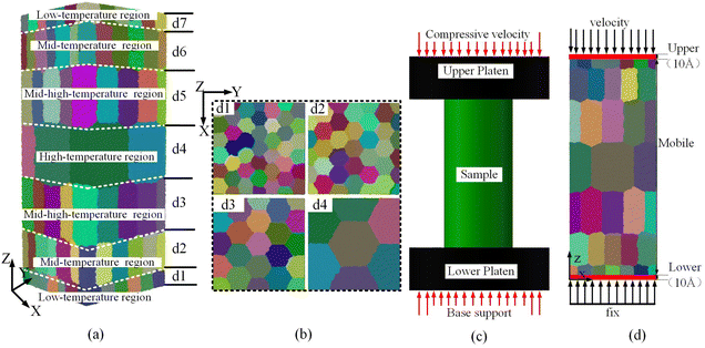 | ||
| Fig. 2 The initial structure of the TA1 gradient model sample: (a) TA1 gradient model; (b) gradient polycrystalline layer; (c) uniaxial compression; and (d) simplified uniaxial compression model. | ||
| Layer | d1 | d2 | d3 | d4 | d5 | d6 | d7 |
| Average grain size/nm | 5 | 10 | 15 | 20 | 15 | 10 | 5 |
| Number of grains | 45 | 39 | 23 | 7 | 23 | 39 | 45 |
2.2 Details of simulation
The simulation is implemented with the software Large-scale Atomic/Molecular Massively Parallel Simulator (LAMMPS),42 and Open Visualization Tool (OVITO) is used to visualize the calculation results.43 Further details of the simulation can be found in Table 2. TA1 belongs to the α-type titanium alloy (also known as industrially pure titanium). Thus, a single many-body potential function can be used in LAMMPS to describe the interaction between Ti–Ti atoms. The potential function serves as the foundation to ensure the reliability of simulation results. Since there are no covalent bonds between metal atoms, the potential function type used for the metal system is a pair style. The Embedded Atom Method (EAM) potential is used to describe the force–field relationship between Ti–Ti atoms. The EAM potential function consists of two parts, as shown in eqn (1). It adds an electron cloud density correlation term to the atomic pair potential, making it more accurate than a simple pair potential.44 In this paper, the EAM potential function for titanium alloys developed by Mendelev's team is utilized.45 | (1) |
| TA1 substrate dimensions | 305.1720 × 305.1720 × 800 Å3 (X, Y, Z direction) |
| Number of atoms in the polycrystalline TA1 | 4![[thin space (1/6-em)]](https://www.rsc.org/images/entities/char_2009.gif) 332 332![[thin space (1/6-em)]](https://www.rsc.org/images/entities/char_2009.gif) 568 568 |
| Compression length | 160 Å |
| Compression velocity (Z-axis) | −0.8 Å ps−1 |
| Equilibration temperature | 300 K |
| Timestep | 0.001 ps |
| Boundary condition | s s s |
3 Results and discussion
3.1 Compression plastic deformation
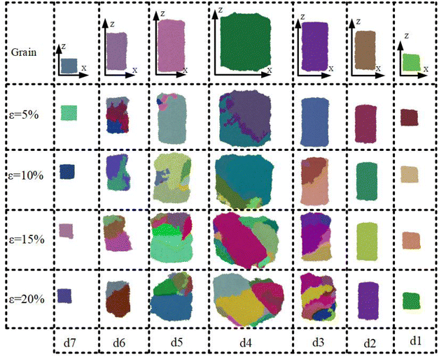
To visualize the deformation of TA1 gradient polycrystals during uniaxial compression, the polyhedral template matching and grain segmentation modules in OVTIO are used to color the polycrystalline grains, with different color blocks indicating different grains. The grain plastic deformation behavior of the TA1 gradient polycrystal during uniaxial compression is shown in Fig. 3. Fig. 3(a) shows the initial structure of the TA1 gradient polycrystal. It can be observed that twin grain boundaries initially emerge within the d6 layer grains, and the model generates slight plastic deformation during the early stages of compressive deformation (ε = 5%). At a deformation level of 10%, a certain quantity of twin boundaries is formed within the grains of layers d1 to d5. The majority of twin boundaries emerge in a state where they penetrate through the grains. Furthermore, the twin boundaries are more prominent in the d5 layer. Simultaneously, a significant number of refined grains emerge in the d6 layer. After the increase of strain (ε = 15–20%), there will be obvious plastic deformation in TA1, accompanied by the generation of a large number of refined grains. As the strain increases, the refinement of the grain is transferred from the d6 layer to the d2 layer. In conclusion, it can be observed that the compressive deformation process of TA1 gradient polycrystals is accompanied by the presence of obvious twinned grain boundaries and the formation of fine crystals. In addition, the degree of refinement varies among the layers of grains in the model, which indicates that the plastic deformation of TA1 gradient polycrystals exhibits a significant grain size effect.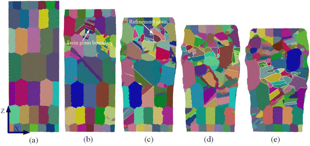 | ||
| Fig. 3 Microstructure of graded polycrystalline TA1 titanium alloy grains under different compressive deformation: (a) initial sample; (b) ε = 5%; (c) ε = 10%; (d) ε = 15%; and (e) ε = 20%. | ||
To further investigate the crystal deformation of TA1 gradient polycrystals during compressive deformation, individual grains from d1 to d7 layers were extracted for analysis, as shown in Fig. 4. Different colors are used to represent different grain orientations, which indicate the lattice torsion of the grains under stress during compression. For the sake of easy comparison and analysis, each grain is taken with reference to the X–Z plane. It can be seen that grains in layers d1, d2 and d7 undergo almost no plastic deformation. After the increase of strain (ε = 0–20%), different degrees of deformation and fine crystallization occur within the grains of layers d3 to d6. Under the same compression conditions, d6 and d2 layer grains with the same grain size have different plastic deformation states. Based on Fig. 3, it can be concluded that plastic deformation can be transferred between different layers. It is noteworthy that the fine crystallization in the d4 layer is almost randomly and uniformly distributed within the grain. However, the deformation of grains in layers d3, d5, and d6 exhibits a clear pattern of transferring along the Z-axis direction from the +Z to −Z axis. These results indicate that grains in the d4 layer have superior deformation stress regulation, while grains in the d1 and d7 layers have superior resistance to deformation.
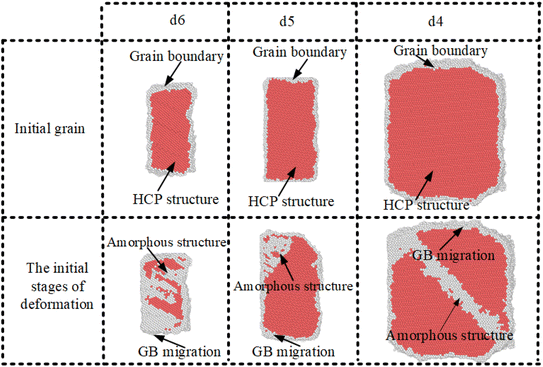
The analysis of Fig. 3 and 4 indicates that only the crystal layers d6, d5, and d4 exhibit significant plastic deformation characteristics in the early stages of deformation. With the increase in strain, the plastic deformation of the grains gradually intensifies. The atomic structure of grains in layers d6, d5, and d4 during the initial deformation stage is shown in Fig. 5. In the initial grains, the grain boundaries are evenly distributed around the atoms with an HCP structure. With the increase in strain, each layer of grains undergoes significant plastic deformation. The atomic distribution structure also undergoes the corresponding changes. This indicates that strain can lead to alterations in the internal atomic structure and positions of the grains. Moreover, there is significant grain boundary migration in the initial grain boundary atoms. It is noteworthy that amorphous structure atoms appear within the grains. The main reason is that strain induces changes in atomic positions, leading to the local rearrangement of the material. The disordered atoms form an amorphous structure.46 The generation of an amorphous structure is beneficial for the dispersion and absorption of stress. It enables the material to respond to stress and strain by making adjustments in its local structure.47,48 During the initial deformation stage, a significant number of amorphous structure atoms appear in the d4 layer. This indicates that the d4 layer of grains exhibits a better ability to adapt to plastic deformation.
3.2 Dislocation motion and stack faults
Crystal plastic deformation can occur through two mechanisms: slip and twinning, but the majority of deformation occurs through slip.49 In general, the main mechanism that causes macroscopic plastic deformation in crystals is the widespread slip of dislocations.50,51 Therefore, the study of dislocation motion is crucial for understanding the intrinsic mechanisms of plastic deformation in polycrystalline materials. The dislocation line distributions for the TA1 gradient polycrystalline model are shown in Fig. 6. In the initial model, the dislocation lines are uniformly distributed at the interface. When ε = 5%, on the one hand, the initial interface dislocations are heavily annihilated, while on the other hand, new dislocations are derived and proliferated. In the area indicated by red arrows in Fig. 6(b), there are newly formed dislocations that appear as interwoven webs or flat strips. With increasing strain, the dislocations become more significantly intertwined and entangled, particularly in the d4 layer of the model, as depicted in Fig. 6(c). When ε = 15%, the derivation and annihilation of dislocation lines almost simultaneously occur. Compared with Fig. 6(c), partially intertwined and entangled dislocations in layers d6, d5, and d4 disappear, while dislocation-derived proliferation occurs in layer d3. It is noteworthy that the percentage of dislocation lines in the d4 layer decreases significantly when ε = 20%. However, the d3 and d2 layers produce intertwined tangles of new dislocation lines, which are especially significant in the d3 layer, as shown in Fig. 6(d). It is evident that the annihilation and generation of dislocations in the plastic deformation process of the TA1 model are a cyclic process. Simultaneously, the accumulation of dislocation generation becomes more significant as the grain size increases.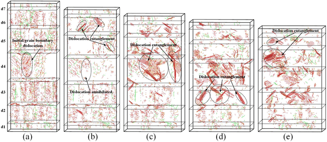 | ||
| Fig. 6 Dislocation distribution under different shape variables: (a) initial sample; (b) ε = 5%; (c) ε = 10%; (d) ε = 15%; and (e) ε = 20%. | ||
Fig. 7 presents the statistics of the number and length of dislocation lines. It can be seen that the dislocation lines with Burgers vectors 〈−1100〉 and 〈0001〉 have a relatively small proportion, and their data fluctuations are not significant. The initial dislocation lines are mostly intertwined and entangled at the interface (white atoms), as shown in point A in Fig. 7(a). At the early stage of deformation (step = 10), there are small decreases in the length and number of incomplete dislocation lines with a Burgers vector of 1/3〈−1100〉 and unit dislocation lines with a Burgers vector of 1/3〈11−20〉. Meanwhile, the entangled dislocation lines at the interface diminish significantly (see point B in Fig. 7(a)). As the strain increases, there is a notable increase in the length and number of dislocations with Burgers vectors of 1/3〈−1100〉 and 1/3〈11−20〉. At this stage, the dislocations primarily proliferate within the crystal (red atoms) and form a mesh-like network (see point C in Fig. 7(a) and point D in Fig. 7(b)). However, at step = 30, there is a slight decrease in both the length and number of dislocation lines, which gradually shift towards the vicinity of the grain boundary atoms (as shown in points E and F in Fig. 7(b)). Therefore, the motion of dislocations is mainly manifested by the annihilation of interface dislocations and the proliferation of intracrystalline dislocations.
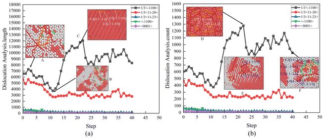 | ||
| Fig. 7 Dislocation counts and length: (a) dislocation analysis: length and (b) dislocation analysis: count. | ||
Stack faults (SFs) are irregularities in the sequence of the dense planes of a crystal. The development of stack faults will reduce the elastic energy. According to Frank's rule, stacking faults arise during the decomposition of lattice dislocations into partial dislocations.52 To investigate the relationship between stacking faults and dislocation, the number of stack fault atoms in the model during plastic deformation is extracted. It can be observed that the number of stacking faults reaches a maximum at the medium stage of deformation, as shown in Fig. 8(a), and a large number of stack fault atomic planes are found around the d4 layer of the TA1 model (see the points from B to D in Fig. 8(a)). The distribution of dislocations in different stages is shown in Fig. 8(b). In the figure, the red colour represents atoms inside the HCP crystal, the gray colour represents atoms at the grain boundary, and the green colour represents atoms at the stack fault. The initial dislocation structure exists in the model in the form of scattered stack fault atoms, as shown in A1. With the increase of the total number of atoms, the stack fault planes gradually accumulate and penetrate through the grain (see the points B1 to D1 in Fig. 8(b)). In general, the formation of incomplete dislocations is often accompanied by the appearance of stacking fault atoms. For HCP crystal materials, stacking faults are commonly formed by the slip of 1/3〈−1100〉 incomplete dislocations on the densely packed surface {0001}.53 The data in Fig. 7 indicate that the motion of incomplete dislocations 1/3〈−1100〉 dominates the plastic deformation of grains. Therefore, the accretion motion of incomplete dislocations 1/3〈−1100〉 is necessarily accompanied by the creation of stack fault atomic surfaces. The creation of stack faults impedes the movement of dislocations, which causes a strengthening effect in the crystal.54
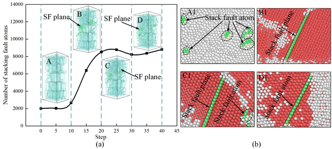 | ||
| Fig. 8 The stacking fault (SF) atom number and distribution: (a) the trend of the number of stack fault atoms and (b) the distribution state of stack fault atoms. | ||
Dislocation density is inextricably linked to crystal strength. By using the dislocation density to characterize the total length of dislocation lines in the model per unit volume, the dislocation density is calculated as shown in eqn (2), where L and V are the total length of the dislocation line (Å) and the total volume of the sample (Å3), respectively.
| ρ = L/V | (2) |
Fig. 9(a) shows the dislocation density variation curve of the gradient polycrystalline model of TA1. Meanwhile, for the purpose of comparison and analysis, the evolution process of dislocations in the layer d4 is presented in Fig. 9(b). At the beginning of the deformation (ε = 5%), the dislocation density of the TA1 model decreases significantly compared to its initial value. The annihilation rate of the initial interface dislocations being higher than the rate of dislocation creation is the main reason for this phenomenon (see A and B in Fig. 9(b)). This is illustrated in Fig. 6 and 7. There is a higher rate of increase in dislocation density when ε = 10%. It is mainly due to the large number of nascent dislocations that are created and propagated within the crystal during this period. When ε = 15%, it can be observed that there is a small decrease in the dislocation density within the crystal. In the later period (ε = 20%), the value of the dislocation density fluctuates within a small range. At this point, there is a dynamic balance between the annihilation of high-density dislocations and the creation of new dislocations. It can also be seen from C to F in Fig. 9(b).
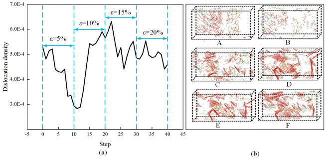 | ||
| Fig. 9 (a) Evolution of the dislocation density as a function of compression deformation and (b) dislocation evolution of the d4 layer. | ||
3.3 Grain boundary migration and plasticity triggering mechanism
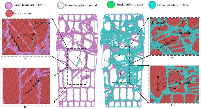
In summary, there is an active dislocation motion during the plastic deformation process of the TA1 gradient model. Under stress, the movement of dislocations at grain boundaries can also promote grain boundary migration. In order to further investigate the plastic deformation mechanism, the migration motion of the grain boundaries in the model is also discussed. Fig. 10 shows the migration motion and local structure of the grain boundaries at the deformation percentage of 0%, 10% and 20%, respectively. To distinguish the grain boundary migration behavior, the initial grain boundary is represented by a gray boundary, the grain boundary with 10% deformation is represented by a purple boundary, and the grain boundary with 20% deformation is represented by a light blue boundary. The red atoms are HCP structures and the green atoms are stack fault atoms. When ε = 10%, there is a significant phenomenon of grain boundary migration compared to the initial position of the grain boundary. At this stage, grain boundary migration is still accompanied by significant twinning, dislocations, and stacking faults, as shown in A1 and B1 in Fig. 10. When ε = 20%, the migration of grain boundaries is more pronounced. This indicates that the migration of grain boundaries becomes more significant with the increase of strain. Meanwhile, the density of the grain boundaries increases constantly, as shown in C1 and D1 in Fig. 10. The increase of grain boundary area also enhances the strength of the material, which is known as work hardening. It is noteworthy that plastic deformation mechanisms, such as twinning, stack faults, and dislocation, are also activated during the process of grain boundary migration. These results indicate that the plastic deformation behavior of the TA1 gradient structure is the result of the interaction of various mechanisms.According to the Hall–Petch relationship, the total area of grain boundaries increases as the grain size decreases. The model includes a total of four levels of grain size in the gradient model of the TA1 titanium alloy. In order to discuss the effect of grain size on the triggering mechanism of plastic deformation, the microscopic changes in grains with different grain sizes are extracted. Fig. 11 shows a schematic of the deformation of a single 20 nm grain. It can be seen that active dislocation motion accompanies the plastic deformation of the grain. The dislocation motion can be divided into three stages: nucleation of dislocations, propagation and entanglement of dislocations, and annihilation of dislocations. As shown in Fig. 11(a) and (b), stack fault atoms (green atoms) are first produced in the crystal, while 1/3〈−1100〉 incomplete dislocations begin to nucleate. In the middle stage, the massive propagation and multiplication of dislocation lines lead to significant plastic deformation of the grains, as shown in Fig. 11(c)–(e). There are obvious high-density dislocation regions and low-density regions within the grain. Meanwhile, it can be observed that a large number of stacked fault atomic surfaces appear in high-density dislocation regions, as shown by the arrows in Fig. 11(d). In the late stage, the high-density dislocation region gradually decreases, as shown in Fig. 11(f)–(h). Most of the dislocations are annihilated at the grain boundaries, and the stack fault atomic planes gradually disappear. Obviously, dislocation motion is the primary triggering mechanism for the grain size of 20 nm grains.
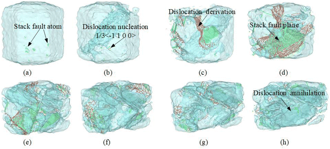 | ||
| Fig. 11 Deformation mechanisms in TA1 with grain size = 20 nm during compression: (a) and (b) dislocation nucleation; (c)–(e) dislocation derivation; and (f)–(h) dislocation annihilation. | ||
Fig. 12 shows schematics of the deformation of single 15 nm, 10 nm and 5 nm grains, respectively. Crystals with a grain size of 5 nm show only minor deformation with increasing strain and do not trigger any significant deformation mechanism. However, plastic deformation in crystals with grain sizes of 15 nm and 10 nm is mainly characterized by the migratory motion at the grain interface. During the pre-deformation stage, plastic deformation in the crystal is mainly exhibited by the migratory motion of grain boundaries. Crystals with a grain size of 10 nm only generate a small number of dislocations in the later stage. The grain size of 15 nm generates noticeable dislocations earlier than the grain size of 10 nm. However, the motion of dislocations within the grains is not significant for both grain sizes. By combining Fig. 5 and 6, it can be observed that at the beginning of deformation, the migratory motion of grain boundaries in smaller grain sizes results in the elimination of a majority of the initial grain boundary dislocations. The movement of dislocations is more prominent in crystals with larger grain size. The migration of grain boundaries is more noticeable in smaller grain sizes. Thus, it can be concluded that the plastic deformation behavior in the TA1 gradient model is significantly influenced by the grain size effect. In addition, this grain size effect has a greater influence on the excitation of the plastic deformation mechanism of the crystal.
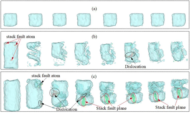 | ||
| Fig. 12 Deformation mechanisms in TA1: (a) grain size = 5 nm; (b) grain size = 10 nm; and (c) grain size = 15 nm. | ||
3.4 Stress distribution
There are different plastic deformation behaviors in functional gradient materials. Therefore, in the TA1 gradient model, the variation of grain size leads to different mechanical properties exhibited by the material at different locations. The grain size effect is an important factor that affects the mechanical properties, fatigue behavior, and crack propagation of materials. Therefore, the distribution of Von Mises stress in the TA1 model during the compression process is discussed, as shown in Fig. 13. Von Mises stress is an important indicator to evaluate the plastic deformation of the metal material.55 In the early stage of compression, the distribution of stress is biased towards the interface region, as shown in Fig. 13(a). This is mainly due to the stress gradient that exists across the volume of the compressed material. The compression process of TA1 gradient polycrystals produces a gradient stress field that varies with the grain size. When ε = 5–15%, it can be observed that there is significant stress concentration in the grains of the d6 and d5 layers, as demonstrated in Fig. 13(b)–(d). However, the stress concentration region in the d4 layer is mainly located at the interface. When ε = 20%, there is a phenomenon of local stress concentration in the grains of the d4 layer. Additionally, the area of stress concentration inside the crystal in the d5 layer significantly increases as indicated by the arrow in Fig. 13(e). It should be noted that the stress concentration regions in the d1 and d7 layers almost always remain at the interfaces. The concentration of stress in the region with larger grain size (20 nm) is generally smaller than that in the region with medium grain size (10 nm and 15 nm) due to the limitation of the grain boundary area. Therefore, the high internal stress in the grain area with medium grain size may lead to the generation and propagation of fatigue cracks. Combining with Fig. 12, it can be seen that the medium grain size mainly releases internal stress through interfacial migration. The large size grains (20 nm) have better grain plasticity due to the relatively small total grain boundary area. Small grain size usually has good resistance to deformation. Therefore, the small grain size region is often the region with the most stable stress state in the TA1 gradient model. The above results indicate that heterogeneous TA1 gradient polycrystals possess excellent strength–ductility properties, simultaneously.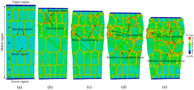 | ||
| Fig. 13 Distribution of Von Mises stress: (a) initial sample; (b) ε = 5%; (c) ε = 10%; (d) ε = 15%; and (e) ε = 20%. | ||
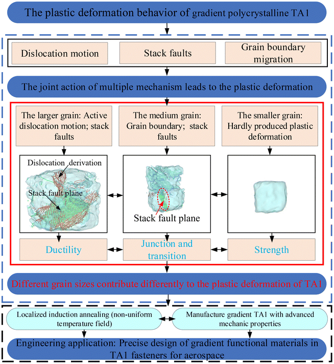
In conclusion, there is active dislocation motion and stacking faults in TA1 gradient polycrystals, as shown in Fig. 14. It is particularly pronounced in larger grains. On one hand, active dislocation motion can effectively enhance the material's ductility.56 It ensures that the material can endure more significant deformation without failure. On the other hand, the increase in dislocation density also enhances the material's strength.57 Under equivalent strain conditions, smaller grain boundaries exhibit hindrance to dislocation motion, leading to an increase in material strength.58,59 It can be concluded that the gradient grains result in a combined multi-mechanism plastic deformation behavior in the TA1 titanium alloy. The above results provide a theoretical foundation for the manufacturing of gradient TA1 materials with advanced mechanical properties. Hence, it is possible to enhance the material's local microstructural performance through the control of dislocation motion (grain size).60 Larger grain size regions are placed in areas where plastic deformation is required (such as the beneficial fold areas of aerospace fasteners). Smaller grain size regions are placed in areas where strength needs to be ensured. Moreover, there should be transitional grains (medium grain size) between small and large grains to ensure a smooth transition between the material's ductility and strength. In the “Method” section of this paper, a method for preparing TA1 gradient functional materials using localized induction annealing technology is described. By subjecting the TA1 material to localized heat treatment using a non-uniform temperature field, the material develops a gradient grain size structure. However, achieving the optimal performance of TA1 gradient materials through the design of reasonable gradient levels is still a research focus for future work.
4 Conclusion
The deformation behavior of the heterogeneous gradient grain TA1 titanium alloy under uniaxial compression is studied by molecular dynamics simulation. The main conclusions are drawn as follows.Under uniaxial compression, there is a significant twinning and grain refinement phenomena in gradient polycrystalline TA1, and as the strain increases, the plastic deformation between each layer of grains exhibits a transmission characteristic along the direction from the +Z to −Z axis. Meanwhile, the deformation of grains in different layers in the model is different. This indicates that the plastic deformation of the gradient TA1 material is closely related to the grain size. The dislocation movement is also active in the TA1 gradient polycrystalline model. During the early stage of deformation, a large number of initial interface dislocations will annihilate due to the migration motion of grain boundaries. However, after the increase of strain, a large amount of dislocation network with coordinated plastic deformation is generated. Due to the asynchronous proliferation–annihilation of dislocations in different layers, the overall dislocation motion in the TA1 model exhibits dynamic cycling.
In the same uniaxial compression environment, the smaller grain size (5 nm) crystals hardly produce plastic deformation. The grain boundary migration of medium grain size (10 nm and 15 nm) crystals dominates in plastic deformation. Crystals with a larger grain size (20 nm) exhibit better deformation regulation. The proliferation of dislocations is the primary triggering mechanism for plastic deformation in crystals. Correspondingly, the proliferation of dislocations is accompanied by the generation of the stacking fault atomic plane. These results indicate that the plastic deformation of gradient polycrystalline TA1 is the outcome of the joint action of multiple mechanisms. In addition, the stress distribution state in layers with different grain sizes demonstrates that TA1 gradient polycrystals possess excellent strength and ductility. Hence, we believe that a progressive gradient structure may be a favorable approach for optimizing the strength and ductility of TA1. In the context of this study, this progressive gradient structure can be achieved by controlling the size of the grains. The combination of large grain layers and small grain layers is used to balance material ductility and strength. Certainly, transition and connection (intermediate grain layer) between strength and ductility are also required.
Author contributions
Yulian Jiang: methodology, software, investigation, validation, writing – original draft, and visualization. Zhiguo Feng: conceptualization, supervision, funding acquisition, and project administration. Liang Tao: methodology, software, resources, and validation.Conflicts of interest
There are no conflicts of interest to declare.Acknowledgements
This work was supported by the National Natural Science Foundation of China (Grant No. 52165042), the Guizhou Provincial Science and Technology Projects (Grant No. 20201Z049), the Excellent Young Talents Project of Guizhou Province (Grant No. 20215617), the Guiyang Municipal Project for Fostering Science and Technology Talents (Grant No. 202143-1), the Guizhou Provincial Science and Technology Projects (Grant No. Y236), and the Science and Technology Program of Guizhou Province (Grant No. 2023308).References
- Y. Kim, G. H. Gu and H. S. Kim, Fundamental analysis of deformation behavior in core-shell heterostructured materials, Comput. Mater. Sci., 2022, 215, 111818, DOI:10.1016/j.commatsci.2023.112076
.
- Z. B. Zhang, W. W. Huang, W. D. Zhao, X. Y. Sun, H. H. Ji, S. B. Yin, J. Chen and L. Gao, Hot Deformation Behavior of TA1 Prepared by Electron Beam Cold Hearth Melting with a Single Pass, Materials, 2023, 16 DOI:10.3390/MA16010369
.
- T. Y. Ma, Y. Wang, C. Yang, Alamusi, Q. B. Deng, Y. Liu, X. Li, Q. Wei and N. Hu, Effect of strain rate on microscale formability and microstructural evolution of TA1 foil, Mater. Sci. Eng., A, 2021, 817, 11, DOI:10.1016/j.msea.2021.141338
.
- Y. Chen, W. C. Xu, D. B. Shan and B. Guo, Study on Microstructure Evolution of TA1 during Plane Compression and its Similarity to Power Spinning, in International Conference on Advanced Design and Manufacturing Engineering (ADME 2011), Trans Tech Publications Ltd, Guangzhou, PEOPLES R. CHINA, 2011, pp. 805–809. DOI:10.3390/ma16010369.
- L. Z. Lu, Y. B. Tian, Y. C. A. Cai, Y. Xin, X. Y. Chen, G. Y. Zhang and J. Han, Microstructure and mechanical properties of a functionally graded material from TA1 to Inconel 625 fabricated by dual wire plus arc additive manufacturing, Mater. Lett., 2021, 298, 4, DOI:10.1016/j.matlet.2021.130010
.
- Y. T. Zhu and X. L. Wu, Heterostructured materials, Prog. Mater. Sci., 2023, 131, 55, DOI:10.1016/j.pmatsci.2022.101019
.
- Y. F. Liu, Y. Cao, Q. Z. Mao, H. Zhou, Y. H. Zhao, W. Jiang, Y. Liu, J. T. Wang, Z. S. You and Y. T. Zhu, Critical microstructures and defects in heterostructured materials and their effects on mechanical properties, Acta Mater., 2020, 189, 129–144, DOI:10.1016/j.actamat.2020.03.001
.
- J. F. Zhao, X. C. Lu, F. P. Yuan, Q. H. Kan, S. X. Qu, G. Z. Kang and X. Zhang, Multiple mechanism based constitutive modeling of gradient nanograined material, Int. J. Plast., 2020, 125, 314–330, DOI:10.1016/j.ijplas.2019.09.018
.
- B. Li, C. M. Niu, T. L. Zhang, G. Y. Chen, G. Zhang, D. Wang, X. Y. Zhou and J. M. Zhu, Advances of machining techniques for gradient structures in multi-principal-element alloys, Rare Met., 2022, 41, 4015–4026, DOI:10.1007/s12598-022-02075-1
.
- R. Ghanavati and H. Naffakh-Moosavy, Additive manufacturing of functionally graded metallic materials: A review of experimental and numerical studies, J. Mater. Res. Technol., 2021, 13, 1628–1664, DOI:10.1016/j.jmrt.2021.05.022
.
- L. Ren, Z. G. Wang, L. Q. Ren, Z. W. Han, Q. P. Liu and Z. Y. Song, Graded biological materials and additive manufacturing technologies for producing bioinspired graded materials: An overview, Composites, Part B, 2022, 242, 23, DOI:10.1016/j.compositesb.2022.110086
.
- Y. Li, Z. Y. Feng, L. Hao, L. J. Huang, C. X. Xin, Y. S. Wang, E. Bilotti, K. Essa, H. Zhang, Z. Li, F. F. Yan and T. Peijs, A Review on Functionally Graded Materials and Structures via Additive Manufacturing: From Multi-Scale Design to Versatile Functional Properties, Adv. Mater. Technol., 2020, 5, 32, DOI:10.1002/admt.201900981
.
- T. H. Fang, W. L. Li, N. R. Tao and K. Lu, Revealing Extraordinary Intrinsic Tensile Plasticity in Gradient Nano-Grained Copper, Science, 2011, 331, 1587–1590, DOI:10.1126/science.1200177
.
- X. Q. Wang and W. Z. Han, Oxygen-gradient titanium with high strength, strain hardening and toughness, Acta Mater., 2023, 246, 11, DOI:10.1016/j.actamat.2023.118674
.
- R. Wang, D. D. Gu, G. J. Huang, K. Y. Shi, L. H. Yuan and H. Zhang, Multilayered gradient titanium-matrix composites fabricated by multi-material laser powder bed fusion using metallized ceramic: Forming characteristics, microstructure evolution, and multifunctional properties, Addit. Manuf., 2023, 62, 12, DOI:10.1016/j.addma.2023.103407
.
- C. Wei, L. C. Liu, H. T. Cao, X. L. Zhong, X. Xu, Y. C. Gu, D. X. Cheng, Y. H. Huang, Z. Q. Li, W. Guo, Z. Liu and L. Li, Cu10Sn to Ti6Al4 V bonding mechanisms in laser-based powder bed fusion multiple material additive manufacturing with different build strategies, Addit. Manuf., 2022, 51, 16, DOI:10.1016/j.addma.2021.102588
.
- T. L. Zhang, Z. H. Huang, T. Yang, H. J. Kong, J. H. Luan, A. D. Wang, D. Wang, W. Kuo, Y. Z. Wang and C. T. Liu, In situ design of advanced titanium alloy with concentration modulations by additive manufacturing, Science, 2021, 374, 478, DOI:10.1126/science.abj3770
.
- C. F. Tey, X. P. Tan, S. L. Sing and W. Y. Yeong, Additive manufacturing of multiple materials by selective laser melting: Ti-alloy to stainless steel via a Cu-alloy interlayer, Addit. Manuf., 2020, 31, 16, DOI:10.1016/j.addma.2019.100970
.
- Z. G. Feng, Y. Li and X. F. Liu, Numerical Analysis of Annealing Process with Local Inductive Heating on A286 Alloy Tube, in 2nd International Conference on Manufacturing Engineering and Intelligent Materials (ICMEIM), Atlantis Press, Hong Kong Informat. Sci. & Engn. Res. Ctr., Guangzhou, PEOPLES R. CHINA, 2017, pp. 488–495.
- S. J. Lu, J. F. Zhao, M. S. Huang, Z. H. Li, G. Z. Kang and X. Zhang, Multiscale discrete dislocation dynamics study of gradient nano-grained materials, Int. J. Plast., 2022, 156, 20, DOI:10.1016/j.ijplas.2022.103356
.
- Z. Y. Feng, H. Li, D. Zhang, X. Guo, Y. Chen and M. Fu, Multi-aspect size effect transition from micro to macroscale: Modelling and experiment, Int. J. Plast., 2022, 156, 35, DOI:10.1016/j.ijplas.2022.103364
.
- M. Y. Jiang, Z. X. Fan, S. Kruch and B. Devincre, Grain size effect of FCC polycrystal: A new CPFEM approach based on surface geometrically necessary dislocations, Int. J. Plast., 2022, 150, 16, DOI:10.1016/j.ijplas.2021.103181
.
- N. M. Pai, A. Prakash, I. Samajdar and A. Patra, Study of grain boundary orientation gradients through combined experiments and strain gradient crystal plasticity modeling, Int. J. Plast., 2022, 156, 29, DOI:10.1016/j.ijplas.2022.103360
.
- M. Rys, S. Stupkiewicz and H. Petryk, Micropolar regularization of crystal plasticity with the gradient-enhanced incremental hardening law, Int. J. Plast., 2022, 156, 20, DOI:10.1016/j.ijplas.2022.103355
.
- T. Yalcinkaya, I. T. Tandogan and I. Ozdemir, Void growth based inter-granular ductile fracture in strain gradient polycrystalline plasticity, Int. J. Plast., 2021, 147, 20, DOI:10.1016/j.ijplas.2021.103123
.
- Z. Zeng, X. Y. Li, D. S. Xu, L. Lu, H. J. Gao and T. Zhu, Gradient plasticity in gradient nano-grained metals, Extreme Mech. Lett., 2016, 8, 213–219, DOI:10.1016/j.eml.2015.12.005
.
- J. J. Li and A. K. Soh, Modeling of the plastic deformation of nanostructured materials with grain size gradient, Int. J. Plast., 2012, 39, 88–102, DOI:10.1016/j.ijplas.2012.06.004
.
- J. Xu, X. W. Liu, X. C. Liu, T. Yan, H. L. Wan, Z. Cao and J. A. Reimer, Deconvolution of metal apportionment in bulk metal-organic frameworks, Sci. Adv., 2022, 8, 8, DOI:10.1126/sciadv.add5503
.
- S. Qian, Y. F. Ni, Y. Gong, F. Yang and Q. Tong, Higher Damping Capacities in Gradient Nanograined Metals, Nano Lett., 2022, 22, 1491–1496, DOI:10.1021/acs.nanolett.1c03600
.
- L. K. Xu, Z. F. Huang, Q. Shen and F. Chen, Atomistic simulations of plasticity heterogeneity in gradient nano-grained FCC metals, Mater. Des., 2022, 221, 16, DOI:10.1016/j.matdes.2022.110929
.
- A. V. Korchuganov, K. P. Zolnikov and D. S. Kryzhevich, The Contribution of Various Plasticity Mechanisms to the Deformation Behavior of Gradient Nanograined FeNi Alloy, Metals, 2022, 12, 13, DOI:10.3390/met12040573
.
- K. Zhou, T. Zhang, B. Liu and Y. J. Yao, Molecular dynamics simulations of tensile deformation of gradient nano-grained copper film, Comput. Mater. Sci., 2018, 142, 389–394, DOI:10.1016/j.commatsci.2017.10.043
.
- J. Sun, H. F. Ye, J. Tao, Q. Li, J. Y. Zhang, L. M. Shen, Y. G. Zheng and H. W. Zhang, Gradient structure regulated plastic deformation mechanisms in polycrystalline nanotwinned copper, J. Phys. D: Appl. Phys., 2019, 52, 11, DOI:10.1088/1361-6463/ab29ca
.
- P. H. Cao, The Strongest Size in Gradient Nanograined Metals, Nano Lett., 2020, 20, 1440–1446, DOI:10.1021/acs.nanolett.9b05202
.
- Y. Liu, F. Yang and J. Zhang, Effects of the grain size gradient on the microstructural evolution in gradient nano-grained copper with initial central crack, Mater. Des. Process. Commun., 2020, 2, e122, DOI:10.1002/mdp2.122
.
- Y. J. Wei, Y. Q. Li, L. C. Zhu, Y. Liu, X. Q. Lei, G. Wang, Y. X. Wu, Z. L. Mi, J. B. Liu, H. T. Wang and H. J. Gao, Evading the strength–ductility trade-off dilemma in steel through gradient hierarchical nanotwins, Nat. Commun., 2014, 5, 8, DOI:10.1038/ncomms4580
.
- X. L. Wu, P. Jiang, L. Chen, F. P. Yuan and Y. T. T. Zhu, Extraordinary strain hardening by gradient structure, Proc. Natl. Acad. Sci. U. S. A., 2014, 111, 7197–7201, DOI:10.1073/pnas.1324069111
.
- C. J. Cheng, X. F. Zhang, M. J. R. Hache and Y. Zou, Phase transition and nanomechanical properties of refractory high-entropy alloy thin films: effects of co-sputtering Mo and W on a TiZrHfNbTa system, Nanoscale, 2022, 14, 7561–7568, 10.1039/d2nr01635d
.
- T. S. Liang, D. J. Zhou, Z. H. Wu, P. P. Shi and X. Y. Chen, Length-dependent dual-mechanism-controlled failure modes in silver penta-twinned nanowires, Nanoscale, 2018, 10, 20565–20577, 10.1039/c8nr03507e
.
- B. Chen, Y. L. Li, D. Sopu, J. Eckert and W. P. Wu, Molecular dynamics study of shock-induced deformation phenomena and spallation failure in Ni-based single crystal superalloys, Int. J. Plast., 2023, 162, 18, DOI:10.1016/j.ijplas.2023.103539
.
- P. Hirel, Atomsk: A tool for manipulating and converting atomic data files, Comput. Phys. Commun., 2015, 197, 212–219, DOI:10.1016/j.cpc.2015.07.012
.
- S. Plimpton, Fast Parallel Algorithms for Short-Range Molecular Dynamics, J. Comput. Phys., 1995, 117, 1–19, DOI:10.1006/jcph.1995.1039
.
- A. Stukowski, Visualization and analysis of atomistic simulation data with OVITO-the Open Visualization Tool, Model. Simul. Mater. Sci. Eng., 2010, 18, 7, DOI:10.1088/0965-0393/18/1/015012
.
- G. J. Ackland, K. D'Mellow, S. L. Daraszewicz, D. J. Hepburn, M. Uhrin and K. Stratford, The MOLDY short-range molecular dynamics package, Comput. Phys. Commun., 2011, 182, 2587–2604, DOI:10.1016/j.cpc.2011.07.014
.
- M. I. Mendelev, T. L. Underwood and G. J. Ackland, Development of an interatomic potential for the simulation of defects, plasticity, and phase transformations in titanium, J. Chem. Phys., 2016, 145, 11, DOI:10.1063/1.4964654
.
- B. Y. Li, A. C. Li, S. Zhao and M. A. Meyers, Amorphization by mechanical deformation, Mater. Sci. Eng., R, 2022, 149, 46, DOI:10.1016/j.mser.2022.100673
.
- Z. Q. Chen, M. C. Li, J. S. Cao, F. C. Li, S. W. Guo, B. A. Sun, H. B. Ke and W. H. Wang, Interface dominated deformation transition from inhomogeneous to apparent homogeneous mode in amorphous/amorphous nanolaminates, J. Mater. Sci. Technol., 2022, 99, 178–183, DOI:10.1016/j.jmst.2021.04.073
.
- L. Wang and J. J. Hoyt, Layering misalignment and negative temperature dependence of interfacial free energy of B2-liquid interfaces in a glass forming system, Acta Mater., 2021, 219, 12, DOI:10.1016/j.actamat.2021.117259
.
- P. D. Ispanovity, D. Ugi, G. Peterffy, M. Knapek, S. Kalacska, D. Tuzes, Z. Dankhazi, K. Mathis, F. Chmelik and I. Groma, Dislocation avalanches are like earthquakes on the micron scale, Nat. Commun., 2022, 13, 10, DOI:10.1038/s41467-022-29044-7
.
- M. Y. Jiang and B. Devincre, Uncovering the existence of anti-backstress associated with dislocations accumulated at grain boundaries during plastic deformation, Comput. Mater. Sci., 2022, 208, 6, DOI:10.1016/j.commatsci.2022.111328
.
- D. X. Wei, W. Gong, T. Tsuru, I. Lobzenko, X. Q. Li, S. Harjo, T. Kawasaki, H. S. Do, J. W. Bae, C. Wagner, G. Laplanche, Y. Koizumi, H. Adachi, K. Aoyagi, A. Chiba, B. J. Lee, H. S. Kim and H. Kato, Si-addition contributes to overcoming the strength-ductility trade-off in high-entropy alloys, Int. J. Plast., 2022, 159, 18, DOI:10.1016/j.ijplas.2022.103443
.
- F. S. Yuan, G. P. Li, C. Z. Liu, F. Z. Han, Y. D. Zhang, A. Muhammad, H. F. Gu, W. B. Guo and J. Ren, Cross stacking faults in Zr(Fe,Cr)2 face-centered cubic Laves phase nanoparticle, Appl. Surf. Sci., 2020, 513, 7, DOI:10.1016/j.apsusc.2020.145716
.
- M. Shih, J. S. Miao, M. Mills and M. Ghazisaeidi, Stacking fault energy in concentrated alloys, Nat. Commun., 2021, 12, 10, DOI:10.1038/s41467-021-23860-z
.
- R. G. Liu, J. Tang, J. X. Jiang, X. Y. Li and Y. J. Wei, Stacking fault induced hardening and grain size effect in nanocrystalline CoNiCrFeMn high-entropy alloy, Extreme Mech. Lett., 2022, 56, 6, DOI:10.1016/j.eml.2022.101875
.
- A. Mangal and E. A. Holm, Applied machine learning to predict stress hotspots I: Face centered cubic materials, Int. J. Plast., 2018, 111, 122–134, DOI:10.1016/j.ijplas.2018.07.013
.
- Y. K. Mu, L. H. He, S. H. Deng, Y. F. Jia, Y. D. Jia, G. Wang, Q. J. Zhai, P. K. Liaw and C. T. Liu, A high-entropy alloy with dislocation-precipitate skeleton for ultrastrength and ductility, Acta Mater., 2022, 232, 14, DOI:10.1016/j.actamat.2022.117975
.
- L. E. Dresselhaus-Marais, G. Winther, M. Howard, A. Gonzalez, S. R. Breckling, C. Yildirim, P. K. Cooks, M. Kutsal, H. Simon, C. Detlefs, J. H. Eggert and H. F. Poulsen, In situ visualization of long-range defect interactions at the edge of melting, Sci. Adv., 2021, 7, 8, DOI:10.1126/sciadv.abe8311
.
- H. X. Li, S. Gao, Y. Tomota, S. Ii, N. Tsuji and T. Ohmura, Mechanical response of dislocation interaction with grain boundary in ultrafine-grained interstitial-free steel, Acta Mater., 2021, 206, 15, DOI:10.1016/j.actamat.2021.116621
.
- S. Kondo, T. Mitsuma, N. Shibata and Y. Ikuhara, Direct observation of individual dislocation interaction processes with grain boundaries, Sci. Adv., 2016, 2, 7, DOI:10.1126/sciadv.1501926
.
- M. Q. Li, Y. D. Shen, K. Luo, Q. An, P. Gao, P. H. Xiao and Y. Zou, Harnessing dislocation
motion using an electric field, Nat. Mater., 2023, 22, 958, DOI:10.1038/s41563-023-01572-7
.
| This journal is © The Royal Society of Chemistry 2024 |


