
Pt nanoparticles on (Ni0.5Co0.5)2P/S-doped carbon nanofibers as electrocatalysts for an efficient hydrogen evolution reaction†
Anqi
Ju
b,
Shuxian
Zhang
b,
Dong
Li
b,
Kunming
Li
b,
Xuepeng
Ni
 b,
Yi
Li
a and
Yang
Jiang
*a
b,
Yi
Li
a and
Yang
Jiang
*a
aNanotechnology Research Institute & College of Materials and Textile Engineering of Jiaxing University, Jiaxing City 314001, Zhejiang Province, P. R. China
bState Key Laboratory for Modification of Chemical Fibers and Polymer Materials & College of Materials Science and Engineering, Donghua University, Shanghai 201620, China
First published on 4th December 2023
Abstract
Owing to the clean and environment friendly advantages, electrochemical water splitting stands out among various hydrogen production strategies. Electrocatalysts play an important role in the hydrogen evolution reaction (HER). Hence, Pt-(Ni0.5Co0.5)2P/S-carbon fibers as electrocatalysts for highly efficient HER were prepared through the structural designing of CNF and heteroatom doping (sulfur (S) or boron (B)). First, three composites of the (Ni0.5Co0.5)2P/carbon fiber ((Ni0.5Co0.5)2P/CNF), (Ni0.5Co0.5)2P/porous carbon fiber ((Ni0.5Co0.5)2P/PCNF), and (Ni0.5Co0.5)2P/hollow porous carbon fiber ((Ni0.5Co0.5)2P/HPCNF) were fabricated via a facile electrospinning with a solvothermal method. (Ni0.5Co0.5)2P/PCNFs showed the smallest overpotential at a current density of 10 mA cm−2 among the three structures. (Ni0.5Co0.5)2P nanosheets loaded on the porous CNF with a large active surface area may expose active sites and shorten the ion transport channel. To improve the catalytic performance of (Ni0.5Co0.5)2P/PCNF, Pt nanoparticles were anchored on (Ni0.5Co0.5)2P/heteroatom doped-PCNF by the chemical reduction method. Pt-(Ni0.5Co0.5)2P/S doped-PCNF exhibited a small overpotential of 64 mV for the HER with 74.9 mV dec−1 Tafel slope and a good stability, which was attributed to the conductive S-doped PCNF facilitating electron transport, accompanying the synergistic effect between the bimetallic phosphide and Pt nanoparticles, thus providing a facile method for an efficient HER electrocatalysis.
Introduction
With the deterioration of the environment by pollution and the depletion of traditional fossil fuels, environment friendly and renewable clean energy sources has attracted widespread attention.1,2 The hydrogen energy is a promising alternative to fossil fuels with its high energy density, efficiency, and cleanliness.3 Water splitting is an effective way to produce hydrogen, which consists of two half-reactions: the hydrogen evolution reaction (HER) at the cathode and oxygen evolution reaction (OER) at the anode.4 However, the overpotential applied to drive water splitting increases the loss of energy; therefore, it is vital to seek efficient catalysts to reduce the energy barrier in water splitting.5 Currently, commercially available catalysts are mainly Pt-based catalysts, such as Pt/C catalysts; however, Pt has limited reserves on the earth and the resulting high cost limits its widespread application.6 The development of low-cost, earth-abundant, and stable catalysts, including metal carbides,7,8 oxides,9 sulfides,10,11 and phosphides,12 are necessary for the HER in commercial applications. Especially, transition metal phosphides (TMPs) show appealing catalytic activity and have been actively studied toward the HER.13,14 For example, MoP,15 Ru2P,16,17 and Co2P exhibit an outstanding HER performance due to their excellent conductivity and stability. However, TMPs often agglomerate during the preparation and reaction process, which reduces their catalytic activity.18,19 Therefore, TMPs are usually combined with substrate materials that have good electrical conductivity and a large specific surface area, including Cu foam, Ni foam,20 and carbon materials, to expose active sites and prevent agglomeration. Among the above substrates, carbon materials, such as carbon nanotubes21 (CNTs), carbon nanofibers22 (CNFs), and graphitized carbon17,23 (GC) have attracted much interest due to their low cost and good conductivity. Liu et al.24 prepared carbon nanotubes decorated with CoP nanocrystals (CoP/CNT) for HER electrocatalysts, which display an onset overpotential of 122 mV and a Tafel slope of 54 mV dec−1. Pin and co-workers used organic–inorganic Mo3O10(C6H8N)2·2H2O as a precursor to obtain N-doped carbon-coated porous MoP nanowires (MoP@NC) for delivering an overpotential of 149 mV in alkaline solution for HER.25 Meanwhile, S. Surendran26 and co-workers prepared carbon nanofiber (CNF) encapsulating NiCoP using the electrospinning method for HER electrocatalysis, which showed a 130 mV overpotential at a current density of 10 mA cm2. The use of heteroatom-doped carbon supports can not only optimize the electronic structure of the catalyst, but also prevents nanosheets from being corroded over the wide range of pH 0–14.27,28 Although many studies have explored carbon materials as electrocatalyst substrates, there are few studies on the effect of structural design and heteroatom doping of carbon substrates on the HER performance. In addition, combining transition metals with less amount of Pt loading as cocatalysts has been attempted to improve the intrinsic activity, this strategy not only reduces the use of Pt, but also significantly improves catalytic performance.29,30In this study, Pt nanoparticles-anchored-(Ni0.5Co0.5)2P/heteroatoms doped-carbon nanofibers, as electrocatalysts for efficient HER, were prepared by electrospinning, solvothermal method, and chemical reduction. Firstly, three kinds of CNF with different structures (CNF, PCNF, HPCNF) were designed as substrates for (Ni0.5Co0.5)2P. (Ni0.5Co0.5)2P/PCNF exhibited the smallest overpotential (164 mV) due to the large active surface area and catalytic active sites. Secondly, Pt nanoparticles and (Ni0.5Co0.5)2P nanosheets were anchored on heteroatom-doped PCNF to promote the HER performance of (Ni0.5Co0.5)2P/PCNF, so that the prepared Pt-(Ni0.5Co0.5)2P/SPCNF may exhibit a small overpotential of 64 mV with a lower Tafel slope (74.9 mV dec−1) for HER at the current density of 10 mA cm−2 with good stability in alkaline electrolytes.
Experimental section
Chemicals
Nickel nitrate hexahydrate (AR, Ni(NO3)2·6H2O) was purchased from Shanghai Titan Scientific Co., Ltd. Cobalt nitrate hexahydrate (AR, Co(NO3)2·6H2O) and urea (AR, CH4N2O) were purchased from Shanghai Macklin Biochemical Co., Ltd. Thiourea (CH4N2S, AR) and boric acid (H3BO3, AR) were purchased from Sinopharm Chemical Reagent Co., Ltd. Methanol (AR, CH4O) was provided by Shanghai Kuling Fine Chemical Co., Ltd. Chloroplatinic acid hexahydrate (H2PtCl6·6H2O) was purchased from Shanghai Aladdin Biochemical Technology Co., Ltd. Potassium hydroxide (AR, KOH) was purchased from Shanghai Hutest Reagent Co., Ltd. Deionized water was used in all the process.Characterization of the materials
Scanning electron microscopy (SEM, Hitachi SU8000) and transmission electron microscopy (TEM and HRTEM, JEM-2100F, JEOL) were performed to observe the morphology and microstructure of the samples. The elemental content and distribution of the sample were characterized using EDS. The crystallinity of samples was analyzed using the X-ray powder diffractometer (XRD, Bruker D2 phaser) with a scan rate of 6° min−1 in the range of 5–70°. The surface composition and the valence state of the elements were characterized by X-ray photoelectron spectroscopy (XPS, Esca Lab 250Xi), and the collected spectral lines were corrected with C 1s peaks. Raman spectrum analysis was used to distinguish the characteristic vibrational modes of the materials, mainly for the D-band and G-band of the carbonized samples.Preparation of different structures of carbon nanofibers.
Typically, 1.0 g of PAN was dissolved in 5.6 g of DMF solution by magnetic stirring for 12 h at 65 °C. Then, the above precursor solution was transferred into a 10 mL spinning syringe in an electrospinning device operating at an extrusion speed of 0.75 mL h−1. The spinning voltage was 14 kV, and the distance between the needle of the syringe and the aluminum foil collector was 15 cm. Finally, the CNF was obtained after stabilization and carbonization. As a comparison, 0.3 g of PMMA was added to the PAN solution to prepare PCNF using the same method. In addition, HPCNF was prepared by coaxial electrospinning. The shell was a DMF solution (17 wt%) of PAN/SAN (95/5), and the core was a DMF solution of SAN (9 wt%). The injection rate of the shell to the core was 3![[thin space (1/6-em)]](https://www.rsc.org/images/entities/char_2009.gif) :1 (0.75:0.25 mL h−1). The as-prepared carbon nanofibers were heated at 280 °C for 120 min in air for stabilization. Finally, the preoxidized nanofibers were carbonized at 800 °C for 120 min under a nitrogen atmosphere to obtain different structures of the carbon nanofibers.
:1 (0.75:0.25 mL h−1). The as-prepared carbon nanofibers were heated at 280 °C for 120 min in air for stabilization. Finally, the preoxidized nanofibers were carbonized at 800 °C for 120 min under a nitrogen atmosphere to obtain different structures of the carbon nanofibers.
Preparation of heteroatom-doped porous carbon nanofiber (X)PCNF
Boron-or sulfur-doped porous carbon nanofibers (X)PCNF, X = (B, S), were prepared by electrospinning followed by stabilization and carbonization. 1.5 g of PAN and 0.45 g of PMMA were dissolved in 7 g DMF in a 50 mL round-bottomed flask for 6 h at 60 °C. Then, 0.36 g of boric acid or thiourea was added to the above solution as a B and S source and stirred for 12 h to obtain a homogeneous solution. The above spinning solution was subsequently placed into a 10 mL syringe tube for electrospinning at a voltage of 14 kV and a distance of 15 cm with a flow rate of 0.75 mL h−1. Afterwards, the samples were stabilized at 280 °C in the air for 2 h and then heated under a nitrogen atmosphere at 800 °C for 2 h, resulting in the formation of B-or S-doped carbon nanofibers (BPCNF/SPCNF).Synthesis of (Ni0.5Co0.5)2P/(X)PCNF
0.5 mmol of Ni (NO3)2·6H2O, 0.5 mmol of Co (NO3)2·6H2O, and 0.5 g of urea were dispersed in 24 mL of mixed solution (16 mL of methanol, 8 mL of water) under magnetic stirring for 30 min. After obtaining a homogeneous solution, the above solution and pre-cleaned SPCNF film were transferred to a 50 mL Teflon-lined stainless steel autoclave and heated to 120 °C for 10 h in a blast drying oven. Finally, the obtained (Ni0.5Co0.5)2OH/SPCNF was washed with deionized water and ethanol several times. A piece 2 × 1 cm2 of (Ni0.5Co0.5)2OH/SPCNF and 300 mg NaH2PO2 (upstream) were placed on both sides of an alumina crucible, which were in the center of a tube furnace and annealed at 300 °C at a heating rate of 2 °C for 2 h under nitrogen atmosphere. After cooling to room temperature, the resultant (Ni0.5Co0.5)2P/SPCNF was obtained. Using the same method as above, (Ni0.5Co0.5)2P/BPCNF and (Ni0.5Co0.5)2P/BSPCNF were also obtained.Fabrication of Pt-(Ni0.5Co0.5)2P/(X)PCNF
A piece of 2 × 1 cm2 Ni0.5Co0.5P/SPCNF film was added to 10 mL of a mixed solution (5 mL of ethanol and 5 mL of water), and then 0.3 mL of H2PtCl4·6H2O (20 mg mL−1) was added to the above mixture under ultrasonic conditions. The solution was then purged with nitrogen for 20 minutes to remove the dissolved oxygen. Then, 5 mL of NaBH4 (0.05 mol L−1) aqueous solution was added dropwise. After that, the mixed solution was stirred for another 20 minutes and left for 1 hour. Finally, the as-prepared Ni0.5Co0.5P/SPCNF was obtained by centrifugation and washed several times with ethanol and deionized water. Pt-(Ni0.5Co0.5)2P/BPCNF, Pt-(Ni0.5Co0.5)2P/BSPCNF and Pt-(Ni0.5Co0.5)2P/PCNF were fabricated using the same method.Electrochemical measurements
The electrocatalytic performance was measured in 1.0 M KOH using a three-electrode system at room temperature. The glass carbon electrode (GCE, 3 mm) was employed as the working electrode, the Hg/HgO electrode was used as the reference electrode and the graphite rod as the counter electrode. Typically, 5 mg catalysts were added to 1 mL of ethanol/water (3:1 v/v) mixed solution, and then 15 μL of 5% Nafion solution was added to obtain a uniform catalyst ink. 6 μL of the above ink was loaded on a clean GCE (0.42 mg cm−2), and dried at 60 °C to prepare the working electrode. All the electrochemical tests were recorded on an electrochemical workstation (IVIUM). (1) The polarization curves of HER were recorded using linear sweep voltammetry (LSV) at a scan rate of 5 mV s−1, the voltage drop was manually compensated by Ecompensated = Emeasured − iRs, where Rs was obtained by EIS. Besides, all the measured potentials were converted into a reversible hydrogen electrode (ERHE = EHg/HgO + 0.098 + 0.059 × PH). (2) The electrochemical active area (ECSA) of the catalyst was calculated by the double-layer capacitance Cdl, which was measured by cyclic voltammetry (CV) in a non-faradaic potential region at different scan rates. (3) Electrochemical impedance spectroscopy (EIS) was performed with a frequency range from 105–10−1 Hz, and 5 mV of the amplitude. (4) The stability was tested from the continuous 2000 CV cycling at a scan rate of 100 mV s−1. Unless otherwise noted, the current density in the electrochemical test results was calculated based on the geometric area of the electrode. All data were measured using iR compensation.
Results and discussion
The schematic diagram of the synthetic process for Pt-(Ni0.5Co0.5)2P/(X)PCNF (X = B, S, or BS) is shown in Scheme 1. Firstly, the carbon nanofibers with different structures CNF, PCNF, and HPCNF were prepared by electrospinning followed by stabilization and carbonization. Secondly, (Ni0.5Co0.5)2P nanosheets were coated on the surface of the carbon nanofibers through hydrothermal and in situ phosphidation. Thirdly, the Pt-(Ni0.5Co0.5)2P/(X)PCNF were obtained by the addition of boric acid or sulfur in the electrospinning solution and deposition of Pt nanoparticles on the surface of (Ni0.5Co0.5)2P/(X)PCNF.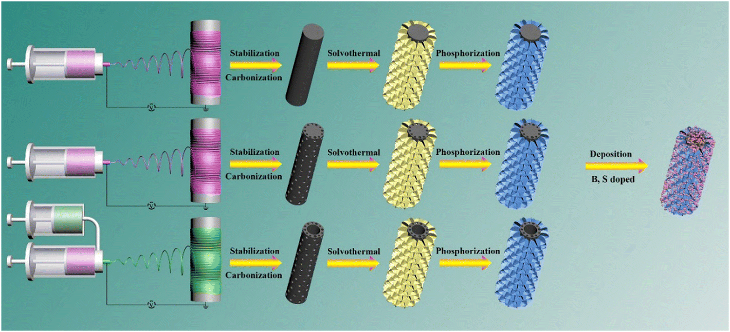 | ||
| Scheme 1 A schematic diagram of a synthetic process for Pt-(Ni0.5Co0.5)2 P/(X)PCNF, X = B, S. | ||
The effect of the Ni/Co ratio in (NixCo1−x)2P on the morphology and electrochemical performance of (NixCo1−x)2P/CNF was studied and the data are shown in Fig. S1–S3 (ESI†). The surface of the carbon nanofiber was uniformly coated with (NixCo1−x)2OH nanosheets for all samples (Fig. S1, ESI†). After the in situ phosphidation, the morphology of (NixCo1−x)2P/CNF remained unchanged (Fig. S2, ESI†). The (Ni0.5Co0.5)2P/CNF composite displayed an overpotential of 179 mV, which was much smaller compared to others as shown in Fig. S3 (ESI†). Therefore, the Ni/Co molar ratio (0.5/0.5) was used in the following studies. The morphologies of (Ni0.5Co0.5)2P/CNF, (Ni0.5Co0.5)2P/PCNF and (Ni0.5Co0.5)2P/HPCNF are shown in Fig. 1a–c. The interconnected nanosheets were evenly distributed on the surface of the carbon fiber and a large number of active sites were introduced, which are vital to the electrocatalytic performance. Moreover, negatively charged P atoms act as proton acceptors, whereas, positively charged metal atoms act as hydride acceptors in NiCoP, both of which are crucial active sites.31,32 Meanwhile, compared to the transition metal oxides, TMPs showed good conductivity and could more effectively accelerate the charge transfer. The porous and hollow porous structures of PCNF and HPCNF are also shown in the insert of Fig. 1b and c. The SEM image of (Ni0.5Co0.5)2P/SPCNF is depicted in Fig. 1d. The diameter (1.5–2 μm) of the heteroatom-doped carbon fibers was significantly larger than that of the undoped carbon nanofibers (400–700 nm) and the Pt nanoparticles were evenly embedded on the surface of (Ni0.5Co0.5)2P/SPCNF. Similar results were also observed in the SEM of Pt-(Ni0.5Co0.5)2P/PCNF, Pt-(Ni0.5Co0.5)2P/BPCNF, and Pt-(Ni0.5Co0.5)2P/BSPCNF, as shown in Fig. S4 (ESI†).
 | ||
| Fig. 1 SEM images of (a) (Ni0.5Co0.5)2P/CNF, (b) (Ni0.5Co0.5)2P/PCNF, (c) (Ni0.5Co0.5)2P/HPCNF, and (d) Pt-(Ni0.5Co0.5)2P/SPCNF. | ||
Fig. 2a shows the transmission electron microscopy (TEM) images of (Ni0.5Co0.5)2P/PCNF, the 3D cross-linked (Ni0.5Co0.5)2P nanosheets were uniformly distributed on the surface of the porous carbon fibers, which was consistent with the SEM results. As shown in the high-resolution transmission microscope (HRTEM) image (Fig. 2b and c), the lattice spacings of 0.22 and 0.20 nm correspond to the (111) and (201) planes of NiCoP, respectively, indicating the successful preparation of bimetal phosphide. Furthermore, the elemental mapping images confirmed that Ni, Co, and P were evenly scattered on the porous carbon nanofibers, as shown in Fig. 2d. The TEM of Pt-(Ni0.5Co0.5)2P/BSPCNF is shown in Fig. S5 (ESI†). The (Ni0.5Co0.5)2P nanosheets were prepared and numerous Pt nanoparticles were distributed on the Pt-(Ni0.5Co0.5)2P/BSPCNF. Moreover, B and S elements could be detected from both elemental mapping and energy dispersive X-ray spectroscopy spectrum (Fig. S6, ESI†), indicating doping of B and S in CNF. All the above results confirmed the preparation of Pt-(Ni0.5Co0.5)2P/BSPCNF.
 | ||
| Fig. 2 (a) TEM and (b) and (c) HRTEM images of the prepared (Ni0.5Co0.5)2P/PCNF and (d) the corresponding element mapping of Ni, Co, P, and C. | ||
XRD analysis was carried out to further study the crystalline structure of the as-prepared composites. The results from the XRD patterns (Fig. 3a) showed that the carbon nanofibers showed a strong characteristic peak at around 26°, which belonged to the (002) crystal facets of graphitic carbon. However, new peaks were observed at 41.07°, 44.92°, 47.64°, and 54.71° for all the composites, which were ascribed to the (111), (201), (210), and (002) crystal planes of the NiCoP crystal phase (JCPDS no. 71-2336). The structure of the carbon fibers had no effect on the crystalline phase of NiCoP. Compared to the above, Pt-(Ni0.5Co0.5)2P/(X)PCNF showed other weak characteristic peaks at around 39.8° and 46.9°, as shown in Fig. S7 (ESI†), belonging to the (111) and (200) planes of the face-centered cubic Pt (JCPDS no. 04-0802), respectively. However, no obvious characteristic peaks of sulfur (S) and boron (B) were observed, mainly because of the small doping amounts. Besides, we also explored the crystalline structure of the composites prepared with different Ni/Co ratios. When there were different Ni/Co molar ratios, the XRD patterns displayed single metal phosphide or bimetallic phosphate characteristic peaks (Fig. S8, ESI†), which corresponded to Ni2P (JCPDS no. 03-0953), NiCoP33 (JCPDS no. 71-2336), and CoP (JCPDS no. 29-0497) phases. The Raman spectra of the composites (Fig. 3b), there were obvious D-band and G-band at 1347 cm−1 and 1590 cm−1, corresponding to the characteristic peaks of amorphous carbon and graphitized carbon, respectively, while the intensity ratios of D and G peaks were 0.951 for PCNF and 0.955 for (Ni0.5Co0.5)2P/PCNF. Similar values indicated that the crystal structure of the carbon fiber was not destroyed by hydrothermal and phosphidation.
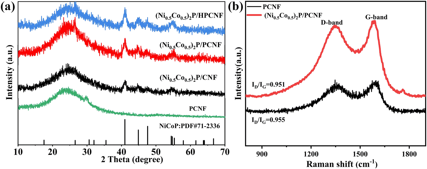 | ||
| Fig. 3 (a) Raman spectra of the PCNF and (Ni0.5Co0.5)2P/PCNF. (b) XRD patterns of the prepared (Ni0.5Co0.5)2P/CNF, (Ni0.5Co0.5)2P/PCNF, and (Ni0.5Co0.5)2P/HPCNF. | ||
The surface chemical composition of (Ni0.5Co0.5)2P/PCNF was characterized by X-ray photoelectron spectroscopy (XPS). The high-resolution spectra of C 1s, P 2p, Ni 2p, and Co 2p are displayed in Fig. 4a–d. The spectrum of C 1s possessed three characteristic peaks corresponding to the C–C bond (284.8 eV), C–O bond (286 eV), and C![[double bond, length as m-dash]](https://www.rsc.org/images/entities/char_e001.gif) C–O bond (288 eV), as shown in Fig. 4a. In the XPS spectrum of P 2p (Fig. 4b), the peaks at 129.1 and 130.2 eV resulted from P 2p3/2 and P 2p1/2, respectively, and one peak (P–O) was located at 133.5 eV, resulting from the material oxidation in air.34 The high-resolution XPS spectrum of Ni 2p showed peaks at different binding energies (Fig. 4c), the two main peaks could be assigned at 856.7 eV and 874.3 eV to Ni 2p3/2 and Ni 2p1/2, respectively, correspond to Ni-P in (Ni0.5Co0.5)2P/PCNF. The two satellite peaks at 864.2 eV and 880.8 eV corresponded to Ni 2p3/2 and Ni 2p1/2, respectively, in Ni–O. For the Co 2p spectrum shown in Fig. 4d, the peaks at 782.21 (Co 2p3/2) are ascribed to Coδ+ in the Co–P compound, and the Co 2p1/2 located at 798.07 eV could be attributed to the oxidized Co species in the Co–P compound.35 Two satellite peaks at 782.2 eV and 798.0 eV, and the peak at 776.75 eV belonged to the Co0+ species. The XPS spectrum of Pt-(Ni0.5Co0.5)2P/SPCNF was recorded and deconvoluted, as shown in Fig. S9 (ESI†). Compared to (Ni0.5Co0.5)2P/PCNF, the binding energy and valence states of Ni, Co, P, and C did not show any obvious changes. Three characteristic peaks appeared in the spectrum of Pt 4f (Fig. S9e, ESI†), the binding energies at 69.5 eV and 72.5 eV are characteristic peaks of Pt 4f7/2, and the binding energies at 74.9 eV and 76.4 eV are assigned to Pt 4f5/2. Due to the S-doping of PCNF, the new peaks appeared at 164.8 eV and 163.6 eV, corresponding to C–S and S–S, respectively (Fig. S9b, ESI†). Based on the above structural information, the preparation of NiCoP nanosheets was well demonstrated.
C–O bond (288 eV), as shown in Fig. 4a. In the XPS spectrum of P 2p (Fig. 4b), the peaks at 129.1 and 130.2 eV resulted from P 2p3/2 and P 2p1/2, respectively, and one peak (P–O) was located at 133.5 eV, resulting from the material oxidation in air.34 The high-resolution XPS spectrum of Ni 2p showed peaks at different binding energies (Fig. 4c), the two main peaks could be assigned at 856.7 eV and 874.3 eV to Ni 2p3/2 and Ni 2p1/2, respectively, correspond to Ni-P in (Ni0.5Co0.5)2P/PCNF. The two satellite peaks at 864.2 eV and 880.8 eV corresponded to Ni 2p3/2 and Ni 2p1/2, respectively, in Ni–O. For the Co 2p spectrum shown in Fig. 4d, the peaks at 782.21 (Co 2p3/2) are ascribed to Coδ+ in the Co–P compound, and the Co 2p1/2 located at 798.07 eV could be attributed to the oxidized Co species in the Co–P compound.35 Two satellite peaks at 782.2 eV and 798.0 eV, and the peak at 776.75 eV belonged to the Co0+ species. The XPS spectrum of Pt-(Ni0.5Co0.5)2P/SPCNF was recorded and deconvoluted, as shown in Fig. S9 (ESI†). Compared to (Ni0.5Co0.5)2P/PCNF, the binding energy and valence states of Ni, Co, P, and C did not show any obvious changes. Three characteristic peaks appeared in the spectrum of Pt 4f (Fig. S9e, ESI†), the binding energies at 69.5 eV and 72.5 eV are characteristic peaks of Pt 4f7/2, and the binding energies at 74.9 eV and 76.4 eV are assigned to Pt 4f5/2. Due to the S-doping of PCNF, the new peaks appeared at 164.8 eV and 163.6 eV, corresponding to C–S and S–S, respectively (Fig. S9b, ESI†). Based on the above structural information, the preparation of NiCoP nanosheets was well demonstrated.
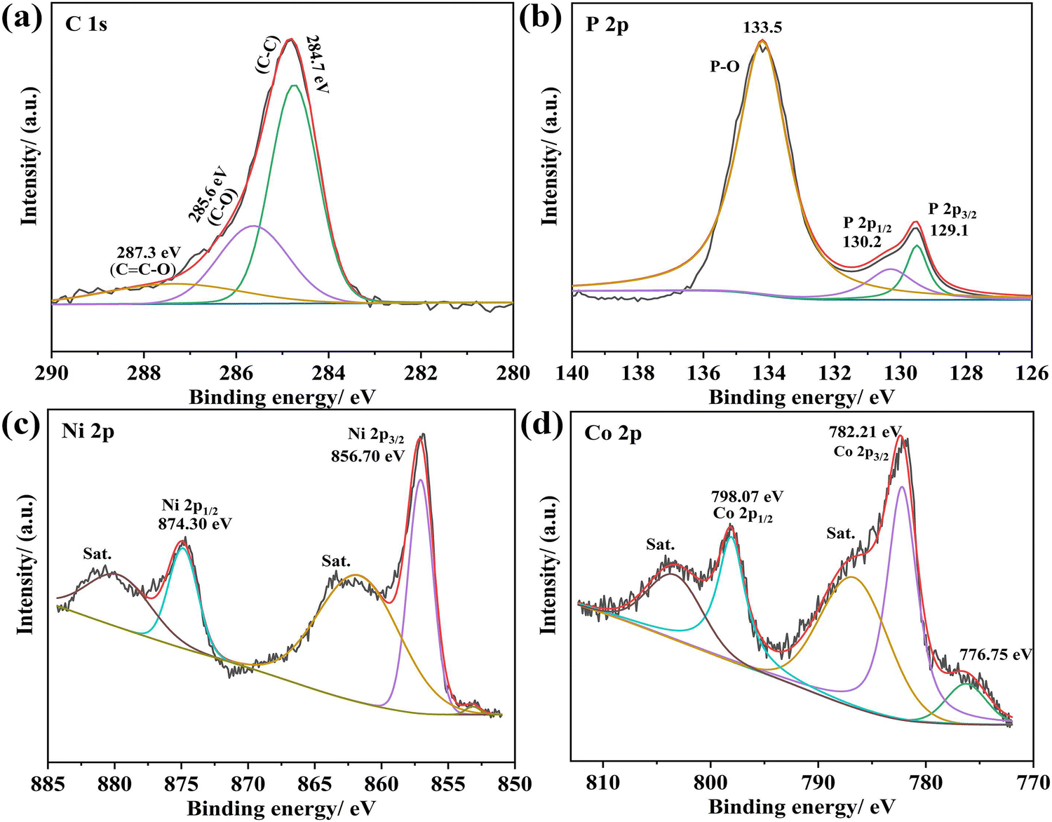 | ||
| Fig. 4 High-resolution XPS spectra of (a) C 1s, (b) Co 2p, (c) Ni 2p, and (d) P 2p of the (Ni0.5Co0.5)2P/PCNF. | ||
The electrocatalytic performances of (Ni0.5Co0.5)2P/CNF, (Ni0.5Co0.5)2P/CNF (Ni0.5Co0.5)2P/PCNF, and (Ni0.5Co0.5)2P/HPCNF composites were measured by a tri-electrode system in 1M KOH solution to study the impact of the CNF structure. The LSV curves with a scan rate of 5 mV s−1 are shown in Fig. 5a. (Ni0.5Co0.5)2P/PCNF showed an overpotential of 164 mV for a current density of 10 mA cm−2. These results indicated that the HER activity of the (Ni0.5Co0.5)2P/PCNF was better than that of the (Ni0.5Co0.5)2P/CNF and (Ni0.5Co0.5)2P/HPCNF, implying that the PCNF with porous structure increased the contact area of the electrode/electrolyte, which was conducive to the rapid transfer of electrons between the (Ni0.5Co0.5)2P nanosheets and the PCNF substrate. The Tafel slopes were analyzed to explore the catalytic kinetics of HER, as shown in Fig. 5b. The Tafel slopes of (Ni0.5Co0.5)2P/PCNF, (Ni0.5Co0.5)2P/CNF, and (Ni0.5Co0.5)2P/PHCNF were 81, 108, and 113 mV dec−1, respectively. The smallest Tafel slope of (Ni0.5Co0.5)2P/PCNF indicates a faster HER catalytic kinetics, and the introduction of the pores into the CNF resulted in stable active sites for the electrode, enhanced conductivity, and a much shorter mass transport length. Additionally, (Ni0.5Co0.5)2P/PCNF exhibited much smaller charge transfer resistance (27.62 Ω) than the others listed in Table S1 (ESI†) according to Fig. 5c, revealing a fast electron transfer. The electrochemical active surface area (ECSA) could explain the roughness of the surface to a certain extent36,37 and was positively correlated with the value of the Cdl and evaluated by cyclic voltammetry (CV) plots at different scan rates (Fig. 5d and Fig. S10, ESI†) during the HER process. It was clear that (Ni0.5Co0.5)2P/PCNF had the largest Cdl (65.4 mF cm−2) which further confirmed the quick electron transfer ability and highly exposed active sites, which are important factors determining the electrocatalytic performance. In NiCoP, negatively charged P atoms act as proton acceptors, while positively charged metal atoms act as hydride acceptors, both of which are crucial active sites. Meanwhile, compared to transition metal oxides, TMPs have good conductivity and can more effectively accelerate charge transfer.
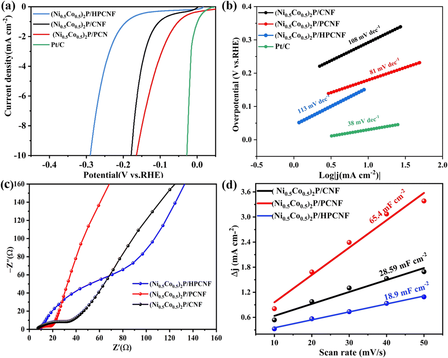 | ||
| Fig. 5 (a) LSV curves, (b) Tafel curves of (Ni0.5Co0.5)2P/CNF, (Ni0.5Co0.5)2P/PCNF, and (Ni0.5Co0.5)2P/HPCNF for HER in 1 M KOH. (c) Nyquist plots curves and (d) Cdl values of (Ni0.5Co0.5)2P/CNF, (Ni0.5Co0.5)2P/PCNF, and (Ni0.5Co0.5)2P/HPCNF. | ||
To further improve the HER performance of (Ni0.5Co0.5)2P/PCNF, Pt nanoparticles and (Ni0.5Co0.5)2P nanosheets were anchored on heteroatom-doped PCNF to prepare Pt-(Ni0.5Co0.5)2P/(X) CNF (X = B, S). The electrochemical properties were investigated in the same electrolyte. As seen in Fig. 6a, among all the obtained electrodes, Pt-(Ni0.5Co0.5)2P/SPCNF exhibited a much-reduced overpotential of 64 mV overpotential at a current density of 10 mA cm−2, well below those of Pt-(Ni0.5Co0.5)2P/PCNF (156 mV), Pt-(Ni0.5Co0.5)2P/BPCNF (323 mV), and Pt-(Ni0.5Co0.5)2P/BSPCNF (258 mV), which is almost on par with the performance of the Pt/C electrode (Fig. 6b). The ultra-high HER activity was attributed to the synergistic effect of the hybridized structure between Pt NPs and (Ni0.5Co0.5)2P. Doping with S could modulate the electronic structure of the carbon atom and enhance its catalytic kinetic process to reduce the overpotential. In addition, The Tafel slope (Fig. 6c) of Pt-(Ni0.5Co0.5)2P/SPCNF (74.9 mV dec−1) was the smallest among the as-prepared Pt-(Ni0.5Co0.5)2P/(X) CNF (X = B, S), indicating a favorable HER kinetics. The Nyquist plots (Fig. 6d) showed a reduced Rct value for the Pt-(Ni0.5Co0.5)2P/SPCNF (72.98 Ω), which was much lower than that of the others (Table S2, ESI†). Besides, the Cdl of the composites (Fig. 6f) could be evaluated by CV plots at different scan rates (Fig. S11, ESI†). The minimum charge transfer resistance for the EIS and the maximum electrochemical double layer capacitance of the ESCA demonstrate that Pt-(Ni0.5Co0.5)2P/SPCNF possesses the largest active surface area, with exposed active sites and the fast electron transfer ability. Sulfur doping of porous carbon fiber (S-PCNF) changes the electron cloud density of the C atom, resulting in defect sites against active sites.38,39 Except for the high electrocatalytic activity, the stability of Pt-(Ni0.5Co0.5)2P/SPCNF for HER was investigated by continuous CV cycles in 1M KOH at a scan rate of 50 mV s−1. After 2000 cycles, the overpotential (Fig. 6e) showed only small changes at a current density of 10 mA cm−2, indicating good stability of Pt-(Ni0.5Co0.5)2P/SPCNF in an alkaline electrolyte.
 | ||
| Fig. 6 (a) LSV curves and (b) comparison of the HER activity. (c) Tafel curves of Pt-(Ni0.5Co0.5)2P/(X)PCNF (X = B, S), (d) Nyquist plots curves, (e) LSV curves before and after 2000 CV cycles in 1 M KOH for Pt-(Ni0.5Co0.5)2P/SPCNF, and (f) Cdl values of (Ni0.5Co0.5)2P/(X)PCNF (X = B, S). | ||
Conclusion
(1) Three types of CNFs with different structures (CNF, PCNF, HPCNF) were designed as substrates of (Ni0.5Co0.5)2P for HER. Based on the electrochemical results of (Ni0.5Co0.5)2P/CNF, (Ni0.5Co0.5)2P/PCNF, and (Ni0.5Co0.5)2P/HPCNF composites, Pt nanoparticle-anchored-(Ni0.5Co0.5)2P/heteroatom-doped carbon nanofibers were prepared to further improve the HER performance of the composites. The electrochemical tests showed that Pt-(Ni0.5Co0.5)2P/SPCNF exhibited excellent HER performance in 1 M KOH with the lowest overpotential of 64 mV at 10 mA cm−2, the smallest Tafel slope, lower charge transfer resistance, and the largest ECSA. The improved catalytic performance was mainly due to the following reasons: (1) the conductive PCNF with a large surface area can prevent (Ni0.5Co0.5)2P nanosheets, and Pt NPs from the agglomeration during the electrocatalytic process and promote rapid charge transfer; (2) doping of S-PCNF with sulfur changed the electron cloud density of the C atom with active sites, which improved the intrinsic activities; (3) high exposure of the active sites from the S-doped PCNF, uniform (Ni0.5Co0.5)2P nanosheets, and Pt NPs originated from the 3D cross-linked structure. The synergistic effect between the S-doped PCNF, (Ni0.5Co0.5)2P nanosheets, and Pt NPs showed excellent catalytic activities for Pt-(Ni0.5Co0.5)2P/SPCNF, making it a particularly a prospective catalyst for hydrogen cracking.Conflicts of interest
There are no conflicts to declare.Acknowledgements
This work was supported by the Fundamental Research Funds for the Central Universities (No. 22D110632), the Open project of the Shanghai Collaborative Innovation Center of High-Performance Fibers and Composites (Province-Ministry Joint, No. X12812101/013), the Key Support Project of the State Key Laboratory for Modification of Chemical Fibers and Polymer Materials (No. 21M1060212) and a Large Aircraft Special Fund of State Key Laboratory for Modification of Chemical Fibers and Polymer Materials (No. 21M1060275). This research was also supported by the Zhejiang Provincial Natural Science Foundation (No. LY22E030012) and the Key Laboratory of Yarn Materials Forming and Composite Processing Technology, Zhejiang Province (No. MTC2019-13).References
- S. E. Habas, H. A. S. Platt, M. F. A. M. V. Hest and D. S. Ginley, Chem. Rev., 2010, 110, 6571–6594 CrossRef CAS.
- S. T. Wismann, J. S. Engbaek, S. B. Vendelbo, F. B. Bendixen, W. L. Eriksen, K. Aasberg-Petersen, C. Frandsen, I. Chorkendorff and P. M. Mortensen, Science, 2019, 364, 756–759 CrossRef CAS.
- T. R. Cook, D. K. Dogutan, S. Y. Reece, Y. Surendranath, T. S. Teets and D. G. Nocera, Chem. Rev., 2010, 110, 6474–6502 CrossRef CAS PubMed.
- Q. Chen, X. Liang, J. Du, Z. Wei, Y.-M. Zhang, T. Zhang, T. Qin, W. Gao, L. Sheng and S. X.-A. Zhang, J. Mater. Chem. C, 2019, 7, 8045–8052 RSC.
- Z. W. Seh, J. Kibsgaard, C. F. Dickens, I. B. Chorkendorff, J. K. Norskov and T. F. Jaramillo, Science, 2017, 355, eaad4998 CrossRef.
- X. Xiong, Y. Ji, M. Xie, C. You and X. Sun, Electrochem. Commun., 2017, 86, 161–165 CrossRef.
- Y. Zhang, Y. Liu, M. Ma, X. Ren, Z. Liu, G. Du, A. M. Asiri and X. Sun, Chem. Comm., 2017, 53, 11048–11051 RSC.
- S. Roy, D. Bagchi, L. Dheer, S. C. Sarma and S. C. Peter, Appl. Catal., B, 2021, 120560 CrossRef CAS.
- R.-Y. Fan, X.-J. Zhai, W.-Z. Qiao, Y.-S. Zhang, N. Yu, N. Xu, Q.-X. Lv, Y.-M. Chai and B. Dong, Nano-Micro Lett., 2023, 15, 190 CrossRef CAS.
- Y. Guo, T. Park, J. W. Yi, J. Henzie, J. Kim, Z. Wang, B. Jiang, Y. Bando, Y. Sugahara and J. Tang, Adv. Mater., 2019, 31, 1807134 CrossRef PubMed.
- K. S. Kim, J. Y. Lee, J. Han, H. S. Hwang and K. Na, Adv. Funct. Mater., 2019, 29, 1970176 CrossRef.
- A. Weingarten, Nat. Nanotechnol., 2018, 13, 4 CrossRef CAS.
- L. M. Cao, J. Zhang, L. W. Ding, Z. Y. Du and C. T. He, J. Energy Chem., 2021, 68, 494–520 CrossRef.
- X. Zhong, K. Huang, Y. Zhang, Y. Wang and S. Feng, ChemSusChem, 2021, 14, 2188–2197 CrossRef CAS.
- J. S. Li, S. Zhang, J. Q. Sha, H. Wang, M. Z. Liu, L. X. Kong and G. D. Liu, ACS Appl. Mater. Interfaces, 2018, 10, 17140–17146 CrossRef CAS.
- S.-H. Cai, X.-N. Chen, M.-J. Huang, J.-Y. Han, Y.-W. Zhou and J.-S. Li, J. Mater. Chem. A, 2022, 10, 772–778 RSC.
- J. S. Li, J. Y. Li, M. J. Huang, L. X. Kong and Z. Wu, Carbon, 2020, 161, 44–50 CrossRef CAS.
- Q. Chen, Q. Zhang, H. Liu, J. Liang, W. Peng, Y. Li, F. Zhang and X. Fan, Small, 2021, 17, 2007858 CrossRef CAS PubMed.
- M. Li, K. Zheng, J. Zhang, X. Li and C. Xu, Appl. Surf. Sci., 2021, 565, 150510 CrossRef CAS.
- S. Yang, J. Y. Zhu, X. N. Chen, M. J. Huang, S. H. Cai, J. Y. Han and J. S. Li, Appl. Catal., B, 2021, 304, 120914 CrossRef.
- K. Kaare, I. Kruusenberg, M. Merisalu, L. Matisen, V. Sammelselg and K. Tammeveski, J. Solid State Electrochem., 2016, 20, 921–929 CrossRef CAS.
- H. Su, H. H. Wang, B. Zhang, K. X. Wang, X. H. Li and J. S. Chen, Nano Energy, 2016, 79–86 CrossRef CAS.
- Y. Shen, Y. Zhou, D. Wang, X. Wu, J. Li and J. Xi, Adv. Energy Mater., 2018, 8, 1701759 CrossRef.
- Q. Liu, J. Tian, W. Cui, P. Jiang, N. Cheng, A. M. Asiri and X. Sun, Angew. Chem., Int. Ed., 2014, 53, 6710–6714 CrossRef CAS.
- C. Pi, C. Huang, Y. Yang, H. Song, X. Zhang, Y. Zheng, B. Gao, J. Fu, P. K. Chu and K. Huo, Appl. Catal., B, 2020, 263, 118358 CrossRef CAS.
- S. Surendran, S. Shanmugapriya, A. Sivanantham, S. Shanmugam and R. K. Selvan, Adv. Energy Mater., 2018, 8, 1800555 CrossRef.
- X. Y. Zhang, Y. R. Zhu, Y. Chen, S. Y. Dou and Y. M. Chai, Chem. Eng. J., 2020, 399, 125831 CrossRef CAS.
- Y.-N. Zhou, Y.-W. Dong, Y. Wu, B. Dong, H.-J. Liu, X.-J. Zhai, G.-Q. Han, D.-P. Liu and Y.-M. Chai, Chem. Eng. J., 2023, 463, 142380 CrossRef CAS.
- R. Kavian, S.-I. Choi, J. Park, T. Liu, H.-C. Peng, N. Lu, J. Wang, M. J. Kim, Y. Xia and S. W. Lee, J. Mater. Chem. A, 2016, 4, 12392–12397 RSC.
- J. Q. Chi, J. Y. Xie, W. W. Zhang, B. Dong, J. F. Qin, X. Y. Zhang, J. H. Lin, Y. M. Chai and C. G. Liu, ACS Appl. Mater. Interfaces, 2019, 11 Search PubMed.
- L. Song, H. Fan and X. Fan, Chem. Eng. J., 2022, 435P431 Search PubMed.
- Z. Jin, P. Li and D. Xiao, Green Chem., 2016, 18, 1459–1464 RSC.
- J. Tian, Q. Liu, A. M. Asiri and X. Sun, J. Am. Chem. Soc., 2014, 136, 7587–7590 CrossRef CAS PubMed.
- Y. Hou, Y. Liu, R. Gao, Q. Li, H. Guo, A. Goswami, R. Zboril, M. B. Gawande and X. Zou, ACS Catal., 2017, 7, 7038–7042 CrossRef CAS.
- E. Hu, Y. Feng, J. Nai, D. Zhao, Y. Hu and X. W. D. Lou, Energy Environ. Sci., 2018, 11, 872–880 RSC.
- P. Zhang, S. Wang, S. Wang and L. Jiang, Small, 2015, 11, 1939–1946 CrossRef CAS.
- T. Wu, M. Pi, X. Wang, W. Guo, D. Zhang and S. Chen, J. Alloys Compd., 2017, 729, 203–209 CrossRef CAS.
- J. Liang, Y. Jiao, M. Jaroniec and S. Z. Qiao, Angew. Chem., Int. Ed., 2012, 51, 11496–11500 CrossRef CAS PubMed.
- K. Qu, Y. Zheng, S. Dai and S. Z. Qiao, Nano Energy, 2016, 19, 373–381 CrossRef CAS.
Footnote |
| † Electronic supplementary information (ESI) available. See DOI: https://doi.org/10.1039/d3nj04456d |
| This journal is © The Royal Society of Chemistry and the Centre National de la Recherche Scientifique 2024 |