High-rate carbon nanotube/magnetic-sheet composites in situ synthesized using a fluidized bed for high-frequency microwave absorption
Lele
Xu
 ,
Chenghui
Sun
,
Chen
Liang
,
Jinsong
Yang
,
Xinxin
Yuan
and
Minghai
Chen
,
Chenghui
Sun
,
Chen
Liang
,
Jinsong
Yang
,
Xinxin
Yuan
and
Minghai
Chen
 *
*
Jiangxi Copper Technology Institute Co., Ltd, Nanchang 330096, P. R. China. E-mail: minghai_chen@sohu.com; Tel: +86-791-88196516
First published on 16th November 2023
Abstract
At present, the large-scale preparation of carbon nanotubes (CNTs) can be achieved by using fluidized bed devices and a chemical vapor deposition (CVD) process. We selected a layered double hydroxide (LDH) as the catalyst carrier, and investigated the effects of different catalyst particle sizes and temperature conditions on the growth of CNTs using a fluidized bed. The catalyst particles of an appropriate size have a significant impact on the fluidization performance and the yield of the final CNTs. Comparing the catalyst particles of 120 mesh, 60 mesh, and 40 mesh sizes, the volume of the product after the 40-mesh catalyst growth is more than 32 times the volume of the initial feedstock added. The ferromagnetic material in the CNTs/magnetic-sheet composite obtained from this bulk in situ preparation combines well with the highly conductive CNTs to achieve a better impedance matching. Benefiting the “wire/capacitor” composite structure, the minimum reflection loss (RL) value of −40.0 dB is achieved at a frequency of 5.0 GHz. More importantly, the effective absorption bandwidth (RL < −10.0 dB) is 3.7 GHz, which occurs in the high frequency (14.3–18.0 GHz) region at a thickness of 1.5 mm. The results show that the composite can be applied to the field of high-frequency microwave absorption.
1. Introduction
The rapid development of radio communication and electronic equipment has brought about efficient microwave transmission channels worldwide. However, this can simultaneously lead to serious electromagnetic (EM) wave pollution problems. Therefore, the demand for electromagnetic wave absorbers (EMAs) is increasingly urgent, in order to pursue their advantages of better compatibility, high absorption rate and thin structure.1,2 Excellent EMAs can effectively reduce the radar cross-section (RCS), which makes it possible for the electromagnetic waves to detect targets.3 When the EM wave propagates to the surface of the material, a part of the wave will reflect at the interface and cannot enter the interior. The other part of its energy entering the interior is converted into other forms of energy through various loss mechanisms to achieve attenuation absorption, and the unattenuated EM waves are transmitted. Therefore, the EMAs that have an excellent wave absorbing performance require two conditions: (1) good impedance matching characteristics, so that the waves can enter the interior; and (2) excellent attenuation, which attenuates the incoming waves and converts it into other energy. Absorbers that satisfy both of the above conditions can achieve efficient absorption.4,5According to the complex requirements, different types of EMAs have been developed. EMAs can be divided into the following two categories according to the loss type: magnetic and dielectric loss materials.3,6 Carbon materials, such as graphene and carbon nanotubes, as well as conductive polymers, are the most studied dielectric components. Iron, nickel, ferrite, and magnetic metal oxides are the components used as magnetic fillers. When using a single type of component, such as a dielectric or magnetic filler, it is usually not possible to achieve a high EM wave absorption performance because it only provides a single type of loss.7,8 Therefore, owing to the good impedance matching and strong interfacial polarization, the combination of the medium and magnetic filler provides a high absorption performance. Currently, due to the multiple demands of the industry, EMAs are also developing towards composite materials. Carbon materials have become one of the most popular absorbing materials due to their advantages of high conductivity and low density.9,10
Carbon nanotubes have exotic physicochemical properties,11 such as unique metallic or semiconductor electrical conductivity,12 high mechanical strength,13 hydrogen storage capacity,14 adsorption capacity15 and strong microwave absorption.16–18 The CNTs were first discovered in the early 1990s, and immediately attracted great attention from the physical, chemical and material science communities.19 At present, the multi-walled carbon nanotubes (MWCNTs) have cost advantages, and are gradually taking over the market of traditional carbon black as reinforcing agents and conductive agents.20 MWCNT conductive pastes have become an indispensable additive material in lithium-ion batteries.21 In order to achieve the large-scale industrial application of CNTs, the problem of low-cost batch preparation of CNTs must be solved first. Currently, there are three main preparation methods, namely, arc discharge,22 laser ablation23 and chemical vapor deposition catalytic cracking.24 The products made by arc discharge and laser evaporation methods have high energy consumption, and the CNTs coexist with other forms of carbon products, which makes the separation and purification difficult. Moreover, the production efficiency and yield decreased, making it difficult to achieve large-scale production.25,26 These two methods are currently mainly used for the study of single-walled carbon nanotubes (SWCNTs).27,28 The CVD catalytic cracking method for preparing CNTs has the advantages of a simple process, low cost, scale control, long length and high yield, which has important research value.29
The catalysts for the preparation of CNTs by CVD are powder materials, usually active metal particles (Fe,30 Co,31 Ni,32etc.) loaded onto an inert matrix (MgO,32,33 Al2O3,34 SiO2,35etc.) with a specific morphology. The active metal particles must be fully expanded and uniformly distributed to obtain excellent results. Otherwise, the lower catalyst utilization rate will affect the yield improvement. Among these powder catalyst materials, layered double hydroxide (LDH), also known as hydrotalcite, has an excellent layered structure that facilitates the dispersion and loading of active metal particles, as well as a simple preparation process, and is widely studied in the preparation of CNT by CVD. Li et al.36 first prepared MWCNT by CVD process with synthesized Co-LDH, which opened the route of CNT preparation using LDH, a new type of highly active catalyst. As the research progressed, Zhao et al.37 found that the introduction of Mo could stabilize the iron nanoparticles in the LDH layer and prevent the aggregation of iron particles, thus enabling the regulation of the size and distribution of iron nanoparticles. Subsequently, Zhang et al.38 discovered the growth mechanism of CNTs in a double helical array on LDH lamellae, which laid the foundation for the large-scale preparation of CNTs from LDH. Zhao et al.39 also applied LDH to a fluidized bed process, and were able to prepare high-quality SWCNTs with 0.95 gCNT (gcat−1 h−1). After the continuous development of the fluidized bed process, the addition of a magnetically assisted fluidized bed is more capable of improving the yield of CNT, and Tian et al.40 were able to prepare CNT bundles of 100 μm length with a yield of 9.1 gCNT gcatal−1 by this process using an LDH catalyst. Obviously, the combination of highly active LDH catalyst and efficient fluidized bed CVD equipment is an effective way to prepare CNT on a large scale.
A fluidized bed, also known as a boiling bed, is suitable for handling large amounts of solid powder catalysts in large-scale preparation, and can substantially increase the amount of CNTs prepared due to the good gas–solid contact of the boiling bed catalytic cracking reaction process.41 In the boiling bed reactor, the raw material gas passes through the gas distribution plate at a certain flow rate, which “blows” the catalyst on the gas distribution plate into a “boiling” state. Catalyst particles are always in a state of motion, and the distance between the catalyst particles is much larger than that in a fixed bed, making it easier for long and straight CNTs to grow on the catalyst surface.42 Due to the mutual collision between the catalyst particles, CNTs are easily dislodged from the catalyst surface. The result of these two effects ensures the formation of straight CNTs with high opening rate. Furthermore, the amount of boiling bed catalyst can be greatly increased, and the feed gas still has sufficient contact with the catalyst surface to ensure high catalyst utilization.43,44 Herein, this study combines the above advantages of fluidized beds, and further optimizes the catalyst granulation process to achieve the large-scale preparation of high-rate and high-quality CNTs. This in situ and efficient preparation of LDH and CNT composites has the advantages of rapid synthesis and cost efficiency, and is bound to be widely applied in the field of EMAs.
In addition to the common characteristics of nanocarbon materials, CNTs have higher Young's modulus and better thermal stability. However, CNTs alone do not perform well as absorbers.45 Due to the influence of the preparation process, the surface of CNTs contains more functional groups and defects, and these characteristics can be of great use in the EM field of nature, which can generate conductivity loss and dipole polarization to consume EM waves through its excellent electrical conductivity.46 However, due to the high dielectric constant and low magnetic permeability of all-carbon materials, the loss of CNTs to electromagnetic waves is mainly dielectric loss, resulting in a series of problems such as poor impedance matching, unsatisfactory electromagnetic absorption performance, and narrow effective absorption bandwidth.47 In order to optimize the impedance matching characteristics, researchers usually prepare composites with other materials with lower dielectric constants or larger permeability, such as ferrite,48 single metals (Fe, Co, Ni),49 metal oxides,50 conductive polymers,51etc., to improve the EM absorption performance and broaden the effective absorption bandwidth.
Therefore, it is crucial to design an ideal EMA with high mechanical properties, light weight, thin thickness, high reflection loss (RL), and broadband absorption (RL < −10 dB in broadband frequency range). The absorption performance of an EMA mainly includes the absorption intensity, effective bandwidth, and absorption thickness. The ability of a EMAs involves the measurement of RL, expressed in decibels. The larger the negative value of RL, the better the attenuation performance of the incident waves. For example, a RL of −10 dB reduces the EM wave power by about 90%, while a RL of −20 dB reduces the wave power by about 99%.52,53 Yuan et al.54 used the solvothermal method to form microwave absorbing composites by embedding CoFe2O4 particles into the mesh of CNTs, and the RL reached −37.39 dB at 1.7 mm thickness with an effective absorption bandwidth (reflection loss below 10 dB) of 5.2 GHz, showing a better absorption capability than pure cobalt ferrite. Jia et al.55 prepared Co/ZnO/C@MWCNTs (CZC@M) composites by pyrolysis of ZnCo-MOF@MWCNTs (MOF@M), where 10% content of MWCNTs gives the optimal dielectric constant and impedance matching properties. The minimum RL of −41.75 dB and the maximum effective absorption bandwidth of 4.72 GHz were obtained for thicknesses of 2.4 mm and 2.2 mm, respectively. Wang et al.56 doped CNTs to give CNT/cellulose carbon aerogel composites with better dielectric loss, and the treated material had a minimum RL of −43.6 dB and an effective absorption bandwidth of 7.42 GHz. Zhang et al.57 prepared necklace-like ferromagnetic carbon-based composites of CNTs compounded with Fe3O4 with a tunable dielectric constant, and the RL reached −38 dB when the size of the tunable microsphere was 400 nm. Zhang et al.58 prepared a novel Co–N–C/CNTsHS microsphere with nitrogen-doped CNTs embedded in Co nanoparticles (Co–N–C) by spray drying and one-step pyrolysis, which benefited from the improved dielectric properties of Co–N–C and exhibited excellent microwave absorption performance. With a thickness of only 2.5 mm, the maximum RL is −60.2 dB and the bandwidth is 5.1 GHz. Researchers have prepared CNTs with low dielectric constant or high magnetic permeability through special processes, which are used for impedance matching of composite materials with specific shapes. Although this method can obtain better microwave absorption performance, the preparation process is still complex, and CNTs are modified or doped intricately.
In this study, by adjusting the particle size of the LDH particles and controlling the temperature in the fluidized bed CVD process, high-rate CNT was prepared. The high multiplicity CNTs with the LDH layer structure were precisely interspersed between the CNT arrays by adding substances with larger magnetic permeability between the highly conductive CNTs. The impedance of this in situ CNTs/magnetic-sheet complex is matched and exhibits excellent microwave absorption performance. More unusually, this in situ combination allows the direct use of the prepared product, further eliminating the subsequent purification steps in CNT applications and reducing the process costs. It is a convenient and efficient approach to synthesizing EMA.
2. Experimental
2.1. Materials and reagents
Aluminum nitrate (Al(NO3)3·9H2O, AR), magnesium nitrate (Mg(NO3)2·6H2O, AR), ammonium molybdate ((NH4)5Mo7O24·4H2O, AR), iron nitrate (Fe(NO3)3·9H2O, AR), urea (CH4N2O, AR) and paraffin wax (pathological grade, melting point of 58–60 °C) were purchased from Sinopharm Chemical Reagent Co., Ltd (China). Hydrogen (H2, 99.99%), ethylene (C2H4, 99.99%), and argon (Ar, 99.99%) were supplied by Nanchang Huayou Special Gas Co., Ltd (China).2.2. Preparation of catalyst
Appropriate amounts of Al(NO3)3·9H2O, Mg(NO3)2·6H2O, Fe(NO3)3·9H2O, (NH4)5Mo7O24·4H2O, and CH4N2O were weighed and dissolved in 150 mL of deionized water, where [Mg2+] = 0.1 mol L−1, [Al3+] = 0.05 mol L−1, and [urea] = 3.0 mol L−1. The resulting suspension was placed in a three-neck flask, condensed and refluxed at 105 °C, continuously magnetically stirred for 12 h, and then aged for another 12 h at 90 °C. After the filtration, washing and drying process, the bulk material consisting of Fe/Mg/Al–Mo42-LDH flakes was successfully obtained. Then, the bulk catalyst was pelletized using a pelletizer (GF-200) with different particle sizes and sieved to obtain 120 mesh, 60 mesh and 40 mesh LDH pellet catalysts, respectively.2.3. Preparation of CNTs
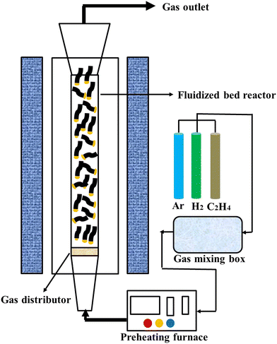
A schematic diagram of the fluidized bed experimental setup for CNTs growth is shown in Fig. 1. A vertical fluidized bed (BTF-1200C-LH-CVD) was used for the CNTs growth experiments, where the furnace tube is a shaped quartz tube with a reaction zone diameter of 30 mm and a height of 500 mm with an enlarged opening above. A gas distributor is embedded in the bottom of the quartz tube reaction zone, which can be used to carry the catalyst particles and allow the gas to pass smoothly. The middle part of the furnace is the reaction heating zone, where the temperature is precisely controlled by a digital temperature controller. The end of the quartz tube is connected to a gas mixer, and the gas flow into the mixer is controlled by a mass flow meter. Initially, 0.5 g (1.5 cm height) of LDH catalyst pellets were placed on a gas distributor inside a quartz tube, which was located in the high temperature zone of the furnace. Ar (2.0 slm) was blown into the system to fluidize the material and the ramp-up rate was controlled at 10 °C min−1 to 800 °C, respectively. H2 (800 sccm) and C2H4 (800 sccm) were separately passed in for the CVD process. After 30 min of reaction time, the supply of H2 and C2H4 was stopped and the setup was naturally cooled to room temperature under argon (1.0 slm). A similar procedure was repeated to synthesize CNTs prepared with different particle sizes of LDH catalysts at different growth temperatures in the range of 750–900 °C. The products prepared at 800 °C with LDH particles of 120 mesh, 60 mesh, and 40 mesh were named 120mCNT800, 60mCNT800, and 40mCNT800, respectively. The products prepared at different temperatures with LDH particles of 40 mesh were named 40mCNT750, 40mCNT800, 40mCNT850, and 40mCNT900, respectively. The final products were stored in a dust- and moisture-free environment.2.4. Characterization
Scanning electron microscope (SEM) photographs of the products were obtained using Apreo SEM (Thermo Fisher Scientific). Due to the good conductivity of the CNT, we can paste the sample directly onto the conductive adhesive for testing without gold spray treatment. Test observations with different resolutions were carried out at a voltage of 5 kV.High-resolution transmission electron microscope (TEM) photographs were obtained with a FEI Tecnai G2 F20S-TWIN apparatus. The sample dispersion in ethanol solvent used an ultrasonic cell crusher (BILON-650Y) to disperse at 500 W power for 30 min. The dispersed samples were dropped onto a copper grid and fed into the equipment for testing under 200 kV accelerated voltage operation.
Raman spectra were recorded on a confocal LabRAM HR Evolution Raman spectroscopic system (HORIBA Scientific) using a 532 nm laser. The thermogravimetric analysis was carried out on a TG 209 F3 (NETZSCH Scientific Instruments) in the temperature range of room temperature to 950 °C in an air atmosphere at a heating rate of 10 °C min−1.
The X-ray diffractometer D8 Advance from Bruker was used to obtain the crystal structure and other information of the samples, with a Cu-Kα source, a wavelength of 1.54 Å, a test tube voltage of 40 kV, a tube current of 40 mA, a scan step of 0.02°, and a dwell time of 0.1 s.
Vector network analyzers are usually used to test the dielectric constant and permeability of the EM-absorbing materials to obtain the reflection loss values by transmission line theory calculations. This experiment uses an Agilent E5071C vector network analyzer to test the EM parameters of the EM-absorbing materials in the frequency range of 2–18 GHz. Test sample preparation process: firstly, the powder to be tested and paraffin wax (5% CNT) are weighed separately according to their respective mass ratios, and heated at 80 °C to melt the paraffin wax. The mixture is then stirred with a glass rod after the paraffin wax melts to evenly mix the powder and paraffin wax, and poured into the ring mold while it is hot. The sample is then quickly pressed into a hollow ring shape with an outer diameter of 7 mm, an inner diameter of 3.04 mm, and a thickness of 2.0–2.5 mm. When the temperature returns to room temperature, the sample is removed and the surface is kept as smooth and unbroken as possible. Finally, the prepared sample is put into the coaxial jig for testing.
3. Results and discussion
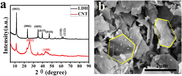
We have characterized the structure and morphology of the prepared LDH catalysts. The XRD spectra of the LDH catalyst and the CNT grown using this catalyst are shown in Fig. 2a. Obviously, the XRD spectrum of the LDH sample exhibits distinctive diffraction peaks of hydrotalcite,59,60 and no characteristic diffraction peaks of other crystalline phases are present. The XRD spectrum gives a series of characteristic diffraction peaks appearing at lower 2θ of 11.6°, 23.7°, respectively, with narrow and sharp peaks, corresponding to a basic layer spacing of 7.7 Å and a high degree of order. The spectra showed obvious (110) and (113) crystallographic diffraction peaks near 60°, characterizing the regularity of the lamellar structure and indicating the good symmetry of the product crystallography. These results show that the synthesized LDH has a single crystalline phase, high order of crystal plane, and intact crystallinity. Meanwhile, the XRD spectrum of the prepared CNT sample showed a broad characteristic diffraction peak near 2θ values of 26.2°, corresponding to the graphitic carbon (002) peak with a crystalline spacing (d = 0.349 nm, PDF No. 75-1621), which proved the presence of a better graphitized structural carbon in the product. On the other hand, three characteristic diffraction peaks of (003), (009) and (015) in LDH are also present near 2θ values of 11.6°, 35.2° and 39.5° with weakened intensity, indicating that most of the products are crystalline CNTs doped with a small amount of LDH lamellae structure.The SEM photograph of the LDH catalyst is shown in Fig. 2b. We can easily identify that part of the LDH maintains a lamellar structure, mainly forming flakes with sizes around 2 μm and thicknesses in the tens of nanometers. Most of the lamellae were broken due to stress during preparation, but the main part can be judged as a hexagonal structure. The scattered distribution of micron-sized flakes has enough gaps between them, which is conducive to gas diffusion and reduces the spatial potential resistance, making it suitable for the high-magnification preparation of CNTs.
The prepared dried LDH catalysts were granulated and graded to obtain granular LDH catalysts of different particle sizes. Catalysts with different particle sizes have significantly different fluidization effects. In fluidized beds, appropriate fluidization rates were achieved by the appropriate particle size and addition amount of the catalysts. Otherwise, the particles exhibit inadequate fluidization in the high temperature process and will form a slab.
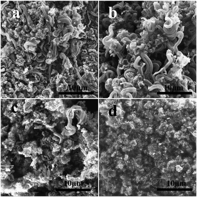
We investigated the surface morphology and microstructure growth of CNTs by SEM. Fig. 3 presents the SEM photographs of the CNTs (120mCNT800, 60mCNT800, 40mCNT800) prepared from the LDH particles with different particle sizes at 800 °C in the fluidized bed CVD process. The fluidization effect of the catalyst and the growth temperature of the nanotubes are important parameters for the fluidized bed process. In the photograph presented in Fig. 3a, when the particle size is 120 mesh, the small size prevents sufficient fluidization of the catalyst. The prepared CNTs were dispersed and agglomerated, and no CNT arrays were observed. Furthermore, low yields of CNTs were noted during the preparation. When the particle size increased to 60 mesh, the formed specimens were a mixture of agglomerated and disordered CNTs and partially arrayed CNTs (Fig. 3b). Continuing to increase the particle size to 40 mesh, a particle consisting of an array of carbon tubes around 100 μm can be observed in Fig. 3c. It is possible that a CNT array was formed by the self-assembly of the CNT product after it was detached from the large particle (around 400 μm) of the catalyst during the fluidized growth process. Further identification (Fig. 3d) reveals curled arrays of CNTs of varying thickness and lengths of tens of microns with more pronounced gaps between the arrays. Although it was still tempting to continue to try smaller particle sizes, the increase in catalyst particle size below 40 mesh led to increased gaps between each other, and there was not enough bed pressure drop in the fluidized bed to allow for proper fluidization.
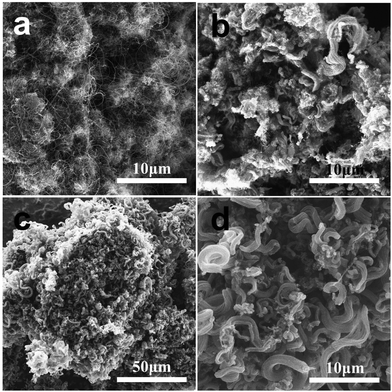 | ||
| Fig. 3 The SEM photographs of CNTs (120mCNT800, 60mCNT800, 40mCNT800) prepared from catalyst particles of different particle sizes: 120 mesh (a), 60 mesh (b), and 40 mesh (c) and (d). | ||
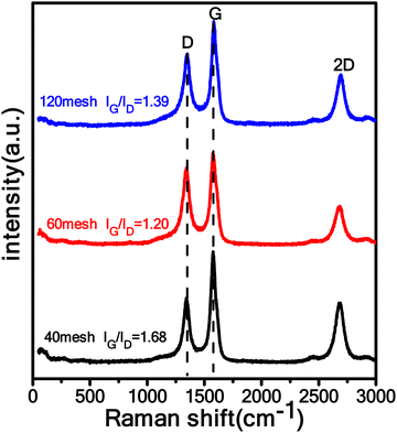
Fig. 4 shows the Raman spectra of the CNT samples (120mCNT800, 60mCNT800, 40mCNT800) prepared by LDH with different particle sizes (120 mesh, 60 mesh and 40 mesh) at 800 °C. There are two particularly prominent peaks in the Raman curves of all three samples, which are the D peak at around 1340 cm−1 and the G peak at around 1580 cm−1. The D peak indicates defects or hybridization in graphite, and the G peak indicates the vibration of carbon atoms in sp2 hybridization. Here, we used the relative intensities of the G and D peaks (IG/ID) to indicate the degree of graphitization of the carbon phase.61 The IG/IDs of the 120 mesh-CNTs, 60 mesh-CNTs, and 40 mesh-CNTs were calculated to be 1.39, 1.20, and 1.68, respectively, with the 40 mesh-CNT product being the highest. This indicates a higher degree of graphitization and lower defects, which is beneficial to improve the electrical conductivity.
In the CVD process, temperature is one of the most critical factors affecting the quality of the product. Different carbon sources have different pyrolysis temperatures, and the fusion state of catalysts at different temperatures is also inconsistent. Therefore, the products prepared by CVD at different temperatures have different morphologies and structures, as shown in Fig. 5. Under the temperature conditions of 750 °C, 800 °C and 850 °C shown in Fig. 5a–c, the SEM photographs show carbon tubes with an obvious array morphology. Especially at 750 °C and 800 °C, the array structure is very obvious and abundant. The coiled carbon tube arrays are intertwined with each other, and the length can reach tens of microns. When the temperature rises to 850 °C, the arrays in Fig. 5c are significantly reduced, and a few arrays are scattered sporadically among the massive agglomerated CNTs. When the temperature rises to 900 °C, no arrays appear in Fig. 5d, forming a product dominated by agglomerated CNTs. It is confirmed that large quantities of long CNT arrays can be prepared only under suitable temperature conditions.
Our previous work confirmed that temperature has a dramatic effect on CNT growth in a fixed-bed CVD process, where the temperature affects not only the crystallization properties, but also the yield of the CNT product.62 In the fluidized bed CVD process, temperature also has a crucial influence. Fig. 6a reflects the Raman spectra of the 40 mesh LDH catalyst particles at different temperatures. The Raman curves of these four different temperature samples also have two prominent characteristic G and D peaks, which are located at around 1340 cm−1 and 1580 cm−1, respectively, in addition to a 2D peak located at around 2700 cm−1, indicating the stacking pattern of the carbon atoms.63 For comparison, there is a huge difference in IG/ID between different temperatures, with the highest IG/ID of 8.44 at 900 °C and decreasing as the temperature decreases to a minimum of 0.97 at 750 °C. Therefore, it is inferred that the IG/ID tends to increase gradually with the increase of the calcination temperature, indicating that the higher graphitization of the carbon phase is beneficial to improve the electrical conductivity.
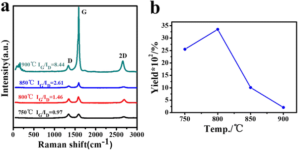 | ||
| Fig. 6 The Raman spectra of CNTs (40mCNT750, 40mCNT800, 40mCNT850, and 40mCNT900) grown at different temperatures of 40 mesh LDH (a) and yield curves (b). | ||
Although the increase in temperature favors the graphitization of the product, it does have a different effect on the yield. In Fig. 6b, the highest yield of 3350% can be achieved with 40mCNT800 at a suitable temperature of 800 °C. However, as the temperature continues to increase, the yield decreases significantly. At 900 °C, although the highest degree of graphitization of the product was obtained at this time, the yield at this time was only 210%. Thus, this proves that the appropriate temperature has a significant role in controlling the graphitization degree and yield of the product.
Fig. 7a shows a physical diagram comparing the volume of the initial material and the final product 40mCNT800 in the furnace tube before and after growth. Distinctly, the height of the catalyst material is 1.5 cm after adding 40 mesh LDH before the reaction. After 30 min of growth in the fluidized bed CVD process at 800 °C, the black product is piled up all over the reaction zone of the furnace tube, reaching a height of 48 cm. The grown CNT increases the volume of the product by more than 32 times. A suitable catalyst particle size and growth temperature control are key to growing CNT at high yield in fluidized bed. The obtained CNT products of this high magnification were studied by a detailed SEM (Fig. 7b–d). In Fig. 7b, the curled arrays of CNTs are intertwined with each other, and the nanotubes are mainly arranged in “bundles”, forming “thick tubes”, which is the array shape. Along the middle of the “thick tube”, a “lamella” can be observed that subtly corresponds to the LDH sheet structure with CNTs growing on both sides of it. This composite stack of highly conductive CNT and magnetic LDH sheet forms a three-dimensional conductive network that exhibits outstanding performance in electromagnetic wave absorption. Fig. 7e and f show the TEM photographs of the above samples, where the dispersed CNTs are arranged in a scattered arrangement without the initial regular array morphology. Among them, the catalyst particles can be identified at the top of a single carbon tube. Fig. 7f shows a single carbon tube selected for detailed identification as a typical MWCNT with eight-layer walls. The photograph presents a very straight carbon tube with an outer diameter of about 10 nm and a wall layer spacing of 0.34 nm. This long and straight MWCNT has fewer defects and a higher degree of graphitization.
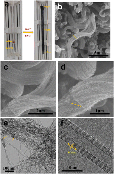 | ||
| Fig. 7 The physical photographs of the fluidized bed before and after growth (a); SEM images of 40mCNT800 at different resolutions (b)–(d) and TEM photographs (e) and (f). | ||
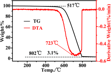
DTA–TG analysis can be employed to comprehensively assess the overall purity of CNTs. In this study, TG was used to assess the thermal stability and purity of the CNTs. The thermal stability and purity of CNTs were assessed by finding the onset point, end point, weight loss curve and residual mass. The temperature at which the solid material begins to decompose is referred to as the onset point, while the end point is the maximum weight loss. It is used as an indicator of the thermal stability of the sample. For MWCNTs, there is no fixed oxidation temperature. However, it usually remains in the range of 400 to 800 °C. The oxidation temperature for amorphous carbon is lower, usually in the range of 200 to 500 °C. In Fig. 8, the 40mCNT800 prepared in this study started to decompose at around 517 °C, and was weight-loss stable by around 802 °C. Verifiably, this CNT has excellent thermal stability with high onset decomposition temperature and termination weight loss temperature. The TG curve tends to be level between the start and 400 °C, indicating that no impurities (such as amorphous carbon) decompose early and the products are all nanotubes. Meanwhile, the final residual amount was 3.1%, indicating a high purity with trace residues of the metal catalyst in the final product. There was only one exothermic peak in the DTA curve, and the fastest weight loss temperature was near 723 °C. It can be confirmed that the 40mCNT800 prepared in this study has high thermal stability and also high purity with about 97% of nanotube content.
Based on the analysis of the experimental results above, it can be concluded that CVD growth using the 40-mesh LDH catalyst particles in a fluidized bed at 800 °C can produce a sample (40mCNT800) with the highest yield and purity. In the large-scale 40mCNT800 prepared in this scheme, the LDH catalyst is properly “embedded” between the CNT arrays. The long CNTs with high crystallinity and few defects are an excellent dielectric component. Moreover, these in situ added LDH catalysts mainly contain ferromagnetic materials, which can appropriately act as magnetic fillers. The perfect combination of the two components creates this carbon nanotube/magnetic sheet composite.
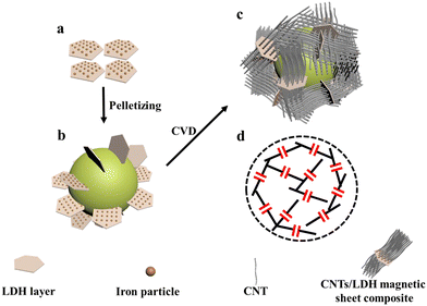
Under this process condition, the in situ formation and large-scale preparation of composites have great advantages in their low cost, which is an ideal choice for EMA. To gain a deeper understanding of the absorbing mode of this high-yield composite, we selected 40mCNT800 for further analysis, as shown in the mechanism diagram in Fig. 9. In the composite material, the CNT has high conductivity. The CNT with the larger aspect ratio can better form a three-dimensional conductive network, which can act as a “wire” in the matrix and has better dielectric loss performance. The LDH magnetic sheet can be considered as a capacitor structure and can act as a “capacitor” in the substrate. As CNT grows on both sides of the LDH sheet layer, the LDH sheet layer is well divided with good conductivity of CNT and has good magnetic loss performance. This in situ formed “wire/capacitor” composite material of the CNT/magnetic sheet with better impedance matching, dielectric loss and magnetic loss work together synergistically to achieve such excellent EM wave absorption properties.64,65
High quality and high yield CNT preparation can be achieved by catalyst size control and temperature regulation in the fluidized bed CVD process. The samples prepared from the materials in this scheme are the most efficient. Simple preparation methods were screened on the basis of previous studies, which have the advantages of low cost and scale-up. Sample preparation conditions are based on the growth rate, morphology control, cost control and other factors, so the microwave absorption properties of the materials prepared under other growth conditions have not been studied. Through the screening and principal analysis of our above experiments, the sample 40mCNT800 prepared by 40 mesh LDH catalyst particles and in 800 °C fluidized bed CVD process is an ideal EMA. This special structural composite of CNTs and magnetic LDH sheets is different from conventional CNT products that require purity requirements. The perfect combination of highly conductive CNT and magnetic LDH, both of which have a natural impedance match, provides excellent performance in the field of EM wave absorption. We selected the sample (40mCNT800) prepared under the optimal process conditions to test the microwave absorption performance for further verification.
Usually, the EM wave absorption performance of materials can be evaluated by the following parameters:
complex permittivity
| εr = ε′ − jε′′, | (1) |
| μr = μ′ − jμ′′, | (2) |
tan![[thin space (1/6-em)]](https://www.rsc.org/images/entities/char_2009.gif) δe = ε′′/ε′, δe = ε′′/ε′, | (3) |
tan![[thin space (1/6-em)]](https://www.rsc.org/images/entities/char_2009.gif) δm = μ′′/μ′. δm = μ′′/μ′. | (4) |
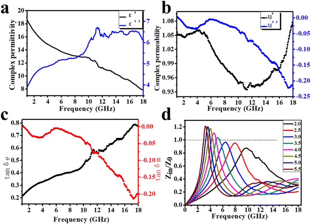
The EM parameters (complex permittivity and complex permeability) are key to analyzing the absorbing properties of the EM wave absorbing materials. The real part (ε′ and μ′) describes the energy storage capacity, while the imaginary part (ε′′ and μ′′) describes the energy dissipation capacity. In Fig. 10a, the value of the real part ε′ in the frequency range of 2–18 GHz shows a decreasing trend between 18 and 8, and this situation is called frequency diffusion. The presence of a clear resonance peak in the ε′′ curve is a reflection of the dipole polarization process occurring in the composite. Meanwhile, the value of ε′′ is proportional to the conductivity, which is more favorable for impedance matching. As indicated in Fig. 10b, μ′ fluctuates above and below 1 as the frequency changes, with peaks near 5 GHz and 18 GHz, while the corresponding μ′′ also shows decreasing peaks at these two frequencies, indicating stronger magnetic losses. The dielectric loss tangent (tan![[thin space (1/6-em)]](https://www.rsc.org/images/entities/char_2009.gif) δe) and magnetic loss tangent (tan
δe) and magnetic loss tangent (tan![[thin space (1/6-em)]](https://www.rsc.org/images/entities/char_2009.gif) δm) represent the electric and magnetic loss capability of the material, respectively, and the larger the value, the stronger the ability to dissipate EM waves. The dielectric loss tangent shows an increasing trend with increasing frequency in the range of 0.2–0.8. Apparently, the magnetic loss tangent exhibits two peaks at similar frequencies in the range of 0–0.23 due to the peak of μ′′ (Fig. 10c). Evidently, the dielectric loss and magnetic loss work together synergistically to exert the EM absorption effect.
δm) represent the electric and magnetic loss capability of the material, respectively, and the larger the value, the stronger the ability to dissipate EM waves. The dielectric loss tangent shows an increasing trend with increasing frequency in the range of 0.2–0.8. Apparently, the magnetic loss tangent exhibits two peaks at similar frequencies in the range of 0–0.23 due to the peak of μ′′ (Fig. 10c). Evidently, the dielectric loss and magnetic loss work together synergistically to exert the EM absorption effect.
The incident wave contains two main parts when it reaches the absorber surface. One part is reflected into the air and the other part is refracted into the absorber. The impedance matching characteristic (Z = Zin/Z0) is an important indicator of the reflection at the interface between the air and the absorber. It depends on the difference between the input characteristic impedance (Zin) and the free space characteristic impedance (Z0). When the Z value is close to 1 (Zin is close to Z0), EM waves can easily enter the absorber and mitigate the reflection. As shown in Fig. 10d, the curves of the Z value with frequency at different thicknesses show peaks above and below 1, all very close to 1, indicating good impedance matching. It can be indicated that more EM waves penetrate the absorber, rather than reflecting into the air.
According to the transmission line theory, the microwave absorption performance of the materials can be determined by the reflection loss (RL) values calculated according to the following equations.66–68
| Zin = Z0(μr/εr)1/2 tanh[j(2πfd/c)(μrεr)1/2] | (5) |
 | (6) |
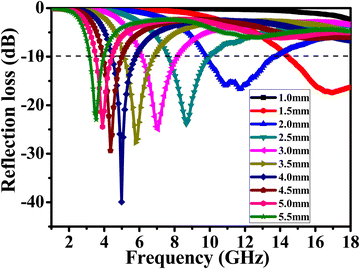
To further investigate the EM absorption characteristics, the reflection loss of samples with different thicknesses was characterized as the frequency varied (Fig. 11). When RL is less than −10 dB, 90% of the EM waves are absorbed by the material, and the corresponding frequency range is called the effective absorption frequency width. The dashed line marked in the figure (RL = −10 dB) shows that the corresponding RL values between 3.2 and 18 GHz are below the dashed line, and the effective absorption frequency width reaches 14.8 GHz. It is particularly important to note that at a thickness of 4.0 mm, the RL reaches a minimum value of −40 dB at a frequency of 5 GHz, proving that the absorption rate at this point can reach 99.99%. Furthermore, at a thickness of 1.5 mm, a long effective absorption frequency width at high frequencies (14.3–18.0 GHz) is achieved. The superior material structure creates a better impedance match to reflect such excellent EM wave absorption performance.
4. Conclusions
Through the pelletizing technique, we screened 40 mesh LDH catalyst particles in a fluidized bed CVD process to prepare 40mCNT800 product with more than 32 times yield. This is an 8-walled CNT with low defect (IG/ID = 1.68). This high-quality, large-scale in situ preparation of the CNTs/LDH magnetic sheet composites has perfect impedance matching. The minimum reflection loss (RL) value is −40.0 dB at 5.0 GHz with 99.99% absorption. More importantly, at a thickness of 1.5 mm, a long effective absorption frequency width at high frequencies (14.3–18.0 GHz) is achieved. Meanwhile, we also note that the CVD growth temperature has a controlling effect on the tube wall and growth multiplicity of CNT, and the EM wave absorption performance of the CNT products with different growth multiplicity and different tube wall deserves further careful study.Author contributions
Minghai Chen, LeLe Xu: conceptualization. LeLe Xu: methodology. LeLe Xu, Chenghui Sun, Chen Liang, Jinsong Yang, XinXin Yuan: software. LeLe Xu: validation. Minghai Chen, LeLe Xu, Chenghui Sun, Jinsong Yang, Chen Liang, XinXin Yuan: formal analysis. LeLe Xu, Chenghui Sun, Chen Liang, Jingsong Yang, XinXin Yuan: investigation. Minghai Chen, LeLe Xu: resources. LeLe Xu, Chen Liang: writing – original draft. Minghai Chen, LeLe Xu, Chenghui Sun, Jinsong Yang: writing – review & editing. LeLe Xu, Chenghui Sun, Chen Liang, Jinsong Yang: data curation. LeLe Xu, Chenghui Sun, Chen Liang: visualization. Minghai Chen: supervision. Minghai Chen: project administration. Minghai Chen: funding acquisition.Conflicts of interest
On behalf of all authors, the corresponding author states that there is no conflict of interest.Acknowledgements
The project was supported by the Double Thousand Talents Program of Jiangxi Province, China (S2018LQCQ0014).References
- H. Zhang, Z. Jia, A. Feng, Z. Zhou, L. Chen, C. Zhang and G. Wu, In situ deposition of pitaya-like Fe3O4@C magnetic microspheres on reduced graphene oxide nanosheets for electromagnetic wave absorber, Composites, Part B, 2020, 199, 108261 CrossRef CAS.
- X. Zhou, H. Han, Y. Wang, C. Zhang, H. Lv and Z. Lou, Silicon-coated fibrous network of carbon nanotube/iron towards stable and wideband electromagnetic wave absorption, J. Mater. Sci. Technol., 2022, 121, 199–206 CrossRef CAS.
- Y. Akinay, U. Gunes, B. Çolak and T. Cetin, Recent progress of electromagnetic wave absorbers: A systematic review and bibliometric approach, ChemPhysMater, 2023, 2, 197–206 CrossRef.
- Y. Akinay, B. Çolak, M. E. Turan, I. N. Akkuş, H. Ç. Kazici and A. O. Kizilçay, The electromagnetic wave absorption properties of woven glass fiber composites filled with Sb2O3 and SnO2 nanoparticles doped mica pigments, Polym. Compos., 2022, 43, 8784–8794 CrossRef CAS.
- T. Guo, S. Chang and Y. Akinay, Synthesis of PPy@Ba0.5Sr0.5Fe12O19/CNFs by reverse in-situ polymerization method for microwave absorption applications, Synth. Met., 2020, 266, 116387 CrossRef CAS.
- C. Zhou, C. Wu, D. Liu and M. Yan, Metal-organic framework derived hi-erarchical Co/C@V2O3 hollow spheres as a thin, lightweight, and high-efficiency electromagnetic wave absorber, Chem. – Eur. J., 2019, 25, 2234–2241 CrossRef CAS.
- H. Niu, P. Liu, F. Qin, X. Liu and Y. Akinay, PEDOT coated Cu-BTC metal-organic frameworks decorated with Fe3O4 nanoparticles and their enhanced electromagnetic wave absorption, Mater. Chem. Phys., 2020, 253, 123458 CrossRef CAS.
- Y. Cao, A. M. Mohamed, M. Mousavi and Y. Akinay, Poly(pyrrole-co-styrene sulfonate)-encapsulated MWCNT/Fe–Ni alloy/NiFe2O4 nanocomposites for microwave absorption, Mater. Chem. Phys., 2021, 259, 124169 CrossRef CAS.
- H. Song, J. Chen, H. Li and Y. Akinay, Preparation of nickel doped mesoporous carbon for enhanced microwave absorption performance, J. Magn. Magn. Mater., 2020, 513, 167071 CrossRef CAS.
- J. Zhou, D. Liu, Y. Xiong and Y. Akinay, A novel approach to prepare polyaniline/Polypyrrole@Cu-BTC/NH2-MIL-101(Fe) MOFs for electromagnetic wave absorption, Ceram. Int., 2020, 46, 19758–19766 CrossRef CAS.
- A. Benko, D. Medina-Cruz, J. Duch, T. Popiela, S. Wilk, M. Bińczak, M. Nocuń, E. Menaszek, L. Geoffrion, G. Guisbiers, A. Kotarba and T. J. Webster, Conductive all-carbon nanotube layers: Results on attractive physicochemical, anti-bacterial, anticancer and biocompatibility properties, Mater. Sci. Eng., C, 2021, 120, 111703 CrossRef CAS PubMed.
- X. Li, F. Zhang, L. L. Zhang, Z. H. Ji, Y. M. Zhao, Z. W. Xu, Y. Wang, P. X. Hou, M. Tian, H. B. Zhao, S. Jiang, L. Q. Ping, H. M. Chen and C. Liu, Kinetics-controlled growth of metallic single-wall carbon nanotubes from CoRex nanoparticles, ACS Nano, 2022, 16, 232–240 CrossRef CAS PubMed.
- K. Bilisik and M. Syduzzaman, Carbon nanotubes in carbon/epoxy multiscale textile preform composites: A review, Polym. Compos., 2021, 42, 1670–1697 CrossRef CAS.
- X. Song, H. Bu, Y. Fan, J. Wang and M. Zhao, Photocatalytic hydrogen production and storage in carbon nanotubes: a first-principles study, RSC Adv., 2022, 12, 17029–17035 RSC.
- D. Yang, A review in tetracycline removal from water environment by carbon nanotubes adsorption, IOP Conf. Ser.: Earth Environ. Sci., 2021, 721, 012014 CrossRef.
- Y. Liu, Y. Zhou, K. Si, S. Bie and J. Jiang, Design of a lattice dielectric cylinder based on multiwalled carbon nanotube-epoxy composite for microwave absorption in the X-band, J. Phys. D: Appl. Phys., 2022, 55, 225304 CrossRef.
- R. Zhao, J. Xia, P. Adamaquaye and G. L. Zhao, High density interfaces enhanced microwave absorption in multifunctional carbon nanotubes-glass fiber-epoxy composites, Polym. Adv. Technol., 2022, 33, 818–830 CrossRef CAS.
- J. Zheng, M. Hanshe, Z. Sun, Y. Chen, S. Jiang, Y. Zhang, Y. Cao, X. Li and E. Shiju, From waste to wealth: Crumb rubber@carbon nanotube/Fe3O4 composites towards highly effective electromagnetic microwave absorption with wide bandwidth, Diamond Relat. Mater., 2022, 126, 109089 CrossRef CAS.
- J. N. Coleman, U. Khan, W. J. Blau and Y. K. Gun’ko, Small but strong: A review of the mechanical properties of carbon nanotube-polymer composites, Carbon, 2006, 44, 1624–1652 CrossRef CAS.
- S. Rathinavel, K. Priyadharshini and D. Panda, A review on carbon nanotube: An overview of synthesis, properties, functionalization, characterization, and the application, Mater. Sci. Eng., B, 2021, 268, 1–28 CrossRef.
- P. Sehrawat, C. Julien and S. S. Islam, Carbon nanotubes in Li-ion batteries: A review, Mater. Sci. Eng., B, 2016, 213, 12–40 CrossRef CAS.
- Y. B. Toleukhanuly, K. M. Kuttybaevna, K. Z. Muratbekovna and N. A. Turlangyzy, Synthesis of carbon nanotubes by the electric arc-discharge method, Ser. Chem. Technol., 2020, 5, 126–133 CrossRef.
- F. H. Alkallas, A. Toghan, H. A. Ahmed, S. H. Alrefaee, R. A. Pashameah, T. A. Alrebdi, E. A. Mwafy and A. M. Mostafa, Catalytic performance of NiO nanoparticles decorated carbon nanotubes via one-pot laser ablation method, J. Mater. Res. Technol., 2022, 18, 3336–3346 CrossRef CAS.
- G. P. Gakis, S. Termine and A. A. Trompeta, Unraveling the mechanisms of carbon nanotube growth by chemical vapor deposition, Chem. Eng. J., 2022, 445, 136807 CrossRef CAS.
- Y. Ando, Carbon nanotube: story in ando laboratory, Journal of Siberian Federal University, Math. Phys., 2010, 3, 3–22 Search PubMed.
- E. A. Mwafy and A. M. Mostafa, Multi walled carbon nanotube decorated cadmium oxide nanoparticles via pulsed laser ablation in liquid media, Opt. Laser Technol., 2019, 111, 249–254 CrossRef CAS.
- A. Fang, L. Sheng, K. An, L. Yu, W. Ren, Y. Ando and X. Zhao, Effect of adding W to Fe catalyst on the synthesis of SWCNTs by arc discharge, Phys. E, 2013, 50, 116–121 CrossRef.
- M. Spellauge, F. Loghin, J. Sotrop, M. Domke, M. Bobinger, A. Abdellah, M. Becherer, P. Lugli and H. P. Huber, Ultra-short-pulse laser ablation and modification of fully sprayed single walled carbon nanotube networks, Carbon, 2018, 138, 234–242 CrossRef CAS.
- M. Kumar and Y. Ando, Chemical vapor deposition of carbon nanotubes: a review on growth mechanism and mass production, J. Nanosci. Nanotechnol., 2010, 10, 3739–3758 CrossRef CAS.
- F. Han, L. Qian, Q. Wu, D. Li, S. Hao, L. Feng, L. Xin, T. Yang, J. Zhang and M. He, Narrow-chirality distributed single-walled carbon nanotube synthesized from oxide promoted Fe-SiC catalyst, Carbon, 2022, 191, 146–152 CrossRef CAS.
- H. Wang, G. Gu, Q. Chen, X. Feng and Y. Chen, Cobalt sulfide catalysts for single-walled carbon nanotube synthesis, Diamond Relat. Mater., 2021, 114, 108288 CrossRef CAS.
- I. Ali, T. S. AlGarni, E. Burakova, A. Tkachev, E. Tugolukov, T. Dyachkova, A. Rukhov, I. Gutnik and E. Galunin, A new approach to the economic synthesis of multi-walled carbon nanotubes using a Ni/MgO catalyst, Mater. Chem. Phys., 2021, 261, 124234 CrossRef CAS.
- T. Tsuji, K. Hata, D. N. Futaba and S. Sakurai, Unexpected efficient synthesis of millimeter-scale single-wall carbon nanotube forests using a sputtered MgO catalyst underlayer enabled by a simple treatment process, J. Am. Chem. Soc., 2016, 138, 16608–16611 CrossRef CAS PubMed.
- A. J. Page, S. Saha, H. B. Li, S. Irle and K. Morokuma, Quantum chemical simulation of carbon nanotube nucleation on Al2O3 catalysts via CH4 chemical vapor deposition, J. Am. Chem. Soc., 2015, 137, 9281–9288 CrossRef CAS.
- Z. Liu, J. Zhao, W. Xu, L. Qian, S. Nie and Z. Cui, Effect of surface wettability properties on the electrical properties of printed carbon nanotube thin-film transistors on SiO2/Si substrates, ACS Appl. Mater. Interfaces, 2014, 6, 9997–10004 CrossRef CAS.
- F. Li, Q. Tan, D. G. Evans and X. Duan, Synthesis of carbon nanotubes using a novel catalyst derived from hydrotalcite-like Co-Al layered double hydroxide precursor, Catal. Lett., 2005, 99, 151–156 CrossRef CAS.
- M. Q. Zhao, Q. Zhang, W. Zhang, J. Q. Huang, Y. Zhang, D. S. Su and F. Wei, Embedded high density metal nanoparticles with extraordinary thermal stability derived from guest-host mediated layered double hydroxides, J. Am. Chem. Soc., 2010, 132, 14739–14741 CrossRef CAS.
- Q. Zhang, M. Q. Zhao, D. M. Tang, F. Li, J. Q. Huang, B. Liu, W. C. Zhu, Y. H. Zhang and F. Wei, Carbon-nanotube-array double helices, Angew. Chem., Int. Ed., 2010, 49, 3642–3645 CrossRef CAS PubMed.
- M. Q. Zhao, Q. Zhang, J. Q. Huang, J. Q. Nie and F. Wei, Layered double hydroxides as catalysts for the efficient growth of high quality single-walled carbon nanotubes in a fluidized bed reactor, Carbon, 2010, 48, 3260–3270 CrossRef CAS.
- G. L. Tian, J. Q. Huang, J. Li, Q. Zhang and F. Wei, Enhanced growth of carbon nanotube bundles in a magnetically assisted fluidized bed chemical vapor deposition, Carbon, 2016, 108, 404–411 CrossRef CAS.
- C. H. See and A. T. Harris, A Review of carbon nanotube synthesis via fluidized-bed chemical vapor deposition, Ind. Eng. Chem. Res., 2007, 46, 997–1012 CrossRef CAS.
- F. Danafar, A. F. Razi and M. A. M. Salleh, Fluidized bed catalytic chemical vapor deposition synthesis of carbon nanotubes-A review, Chem. Eng. J., 2009, 155, 37–48 CrossRef CAS.
- K. Dasgupta, J. B. Joshi, H. Singh and S. Banerjee, Fluidized bed synthesis of carbon nanotubes: Reaction mechanism, rate controlling step and overall rate of reaction, AIChE J., 2014, 60, 2882–2892 CrossRef CAS.
- G. Allaedini, P. Aminayi and S. M. Tasirin, Methane decomposition for carbon nanotube production: Optimization of the reaction parameters using response surface methodology, Chem. Eng. Res. Des., 2016, 112, 163–174 CrossRef CAS.
- J. Liu, L. Zhang and H. Wu, Electromagnetic wave-absorbing performance of carbons, carbides, oxides, ferrites and sulfides: review and perspective, J. Phys. D: Appl. Phys., 2021, 54, 203001 CrossRef.
- D. Dragoman and M. Dragoman, Electromagnetic wave propagation in dense carbon nanotube arrays, J. Appl. Phys., 2006, 99, 076106 CrossRef.
- B. Li, C. Wang and W. Wang, Progress of electromagnetic wave absorbing materials based on carbon, Mater. Rev., 2012, 26, 9–14 CAS.
- R. K. Srivastava, P. Xavier, S. N. Gupta, G. P. Kar, S. Bose and A. K. Sood, Excellent electromagnetic interference shielding by graphene-MnFe2O4-multiwalled carbon nanotube hybrids at very low weight percentage in polymer matrix, ChemistrySelect, 2016, 1, 5995–6003 CrossRef CAS.
- X. Qi, J. Xu, Q. Hu, W. Zhong and Y. Du, Preparation, electromagnetic and enhanced microwave absorption properties of Fe nanoparticles encapsulated in carbon nanotubes, Mater. Sci. Eng., B, 2015, 198, 108–112 CrossRef CAS.
- G. Wu, Y. He, H. Zhan, Q. Q. Shi and J. N. Wang, A novel Fe3O4/carbon nanotube composite film with a cratered surface structure for effective microwave absorption, J. Mater. Sci.: Mater. Electron., 2020, 31, 11508–11519 CrossRef CAS.
- D. A. Makeiff and T. Huber, Microwave absorption by polyaniline-carbon nanotube composites, Synth. Met., 2006, 156, 497–505 CrossRef CAS.
- J. Deng, Q. Wang, Y. Zhou, B. Zhao and R. Zhang, Facile design of a ZnO nanorod-Ni core-shell composite with dual peaks to tune its microwave absorption properties, RSC Adv., 2017, 7, 9294–9302 RSC.
- Y. Akinay, F. Hayat, Y. Kanbur, H. Gokkaya and S. Polat, Comparison of microwave absorption properties between BaTiO3/Epoxy and NiFe2O4/Epoxy composites, Polym. Compos., 2018, 39, E2143–E2148 CAS.
- Y. Yuan, S. Wei, Y. Liang, B. Wang, Y. Wang, W. Xin, X. Wang and Y. Zhang, Solvothermal assisted synthesis of CoFe2O4/CNTs nanocomposite and their enhanced microwave absorbing properties, J. Alloys Compd., 2021, 867, 159040 CrossRef CAS.
- Z. Jia, M. Kong, B. Yu, Y. Ma, J. Pan and G. Wu, Tunable Co/ZnO/C@MWCNTs based on carbon nanotube-coated MOF with excellent microwave absorption properties, J. Mater. Sci. Technol., 2022, 127, 153–163 CrossRef CAS.
- Y. Y. Wang, Z. H. Zhou, J. L. Zhu, W. J. Sun, D. X. Yan, K. Dai and Z. M. Li, Low-temperature carbonized carbon nanotube/cellulose aerogel for efficient microwave absorption, Composites, Part B, 2021, 220, 108985 CrossRef CAS.
- M. Zhang, S. Song, Y. Liu, Z. Hou, W. Tang and S. Li, Microstructural design of necklace-like Fe3O4/multiwall carbon nanotube (MWCNT) composites with enhanced microwave absorption performance, Materials, 2021, 14, 4783 CrossRef CAS PubMed.
- C. Zhang, G. Chen, R. Zhang, Z. Wu, C. Xu, H. Man and R. Che, Charge modulation of CNTs-based conductive network for oxygen reduction reaction and microwave absorption, Carbon, 2021, 178, 310–319 CrossRef CAS.
- X. B. Fu, H. Yu, F. Peng, H. J. Wang and Y. Qian, Facile preparation of RuO2/CNT catalyst by a homogenous oxidation precipitation method and its catalytic performance, Appl. Catal., A, 2007, 321, 190–197 CrossRef CAS.
- H. L. Zhang, Y. Zhang, X. G. Zhang, F. Li, C. Liu, J. Tan and H. M. Cheng, The facile synthesis of nickel silicide nanobelts and nanosheets and their application in electrochemical energy storage, Carbon, 2006, 44, 2778–2784 CrossRef CAS.
- A. Jorio and R. Saito, Raman spectroscopy for carbon nanotube applications, J. Appl. Phys., 2021, 129, 021102 CrossRef CAS.
- L. Xu, Y. Cao, X. Yuan, C. Liang, Z. Yong and M. Chen, Effective self-support growth of spring-like carbon nanotube arrays with ultra-large specific surface area, NANO, 2022, 17, 2250074 CrossRef CAS.
- M. S. Dresselhaus, G. Dresselhaus, R. Saito and A. Jorio, Raman spectroscopy of carbon nanotubes, Phys. Rep., 2005, 409, 47–99 CrossRef.
- Y. Wang, G. Wang, X. Zhang and C. Gao, Porous carbon polyhedrons coupled with bimetallic CoNi alloys for frequency selective wave absorption at ultralow filler loading, J. Mater. Sci. Technol., 2022, 103, 34–41 CrossRef CAS.
- S. Zhang, J. Wu, W. Liang, P. Zhao, H. Wang, Y. Cong and G. Wang, Flexible and multifunctional polyimide-based composite films by self-reducing reaction for electromagnetic interference shielding in extreme environments, Carbon, 2023, 212, 118103 CrossRef CAS.
- Y. Akinay, F. Hayat, M. Cakir and E. Akin, Magnetic and microwave absorption properties of PVB/Fe3O4 and PVB/NiFe2O4 composites, Polym. Compos., 2018, 39, 3418–3423 CrossRef CAS.
- Y. Akinay and A. O. Kizilcay, Computation and modeling of microwave absorbing CuO/graphene nanocomposites, Polym. Compos., 2020, 41, 227–232 CrossRef CAS.
- P. Zhao, H. Wang, B. Cai, X. Sun, Z. Hou, J. Wu, M. Bai and G. Wang, Electrospinning fabrication and ultra-wideband electromagnetic wave absorption properties of CeO2/N-doped carbon nanofibers, Nano Res., 2022, 15, 7788–7796 CrossRef CAS.
| This journal is © The Royal Society of Chemistry and the Centre National de la Recherche Scientifique 2024 |

