
 Open Access Article
 This Open Access Article is licensed under a
 Creative Commons Attribution 3.0 Unported Licence
Demonstration of tritium adsorption on graphene†
Genrich
Zeller
 *a,
Desedea
Díaz Barrero
ab,
Paul
Wiesen
a,
Simon
Niemes
a,
Nancy
Tuchscherer
a,
Max
Aker
a,
Artus M. W.
Leonhardt
a,
Jannik
Demand
a,
Kathrin
Valerius
c,
Beate
Bornschein
a,
Magnus
Schlösser
a and
Helmut H.
Telle
b
*a,
Desedea
Díaz Barrero
ab,
Paul
Wiesen
a,
Simon
Niemes
a,
Nancy
Tuchscherer
a,
Max
Aker
a,
Artus M. W.
Leonhardt
a,
Jannik
Demand
a,
Kathrin
Valerius
c,
Beate
Bornschein
a,
Magnus
Schlösser
a and
Helmut H.
Telle
b
aTritium Laboratory Karlsruhe (TLK), Institute for Astroparticle Physics (IAP), Karlsruhe Institute of Technology (KIT), Hermann-von-Helmholtz-Platz 1, 76344 Eggenstein-Leopoldshafen, Germany. E-mail: genrich.zeller@kit.edu
bDepartamento de Química Física Aplicada, Universidad Autónoma de Madrid, Campus de Cantoblanco, 28049 Madrid, Spain
cInstitute for Astroparticle Physics (IAP), Karlsruhe Institute of Technology (KIT), Hermann-von-Helmholtz-Platz 1, 76344 Eggenstein-Leopoldshafen, Germany
First published on 27th March 2024
Abstract
In this work, we report on studies of graphene exposed to tritium gas in a controlled environment. The single layer graphene on a SiO2/Si substrate was exposed to 400 mbar of T2, for a total time of ∼55 h. The resistivity of the graphene sample was measured in situ during tritium exposure using the van der Pauw method. We found that the sheet resistance increases by three orders of magnitude during the exposure, suggesting significant chemisorption of tritium. After exposure, the samples were characterised ex situ via spatio-chemical mapping with a confocal Raman microscope, to study the effect of tritium on the graphene structure (tritiation yielding T-graphene), as well as the homogeneity of modifications across the whole area of the graphene film. The Raman spectra after tritium exposure were comparable to previously observed results in hydrogen-loading experiments, carried out by other groups. By thermal annealing we also could demonstrate, using Raman spectral analysis, that the structural changes were largely reversible. Considering all observations, we conclude that the graphene film was at least partially tritiated during the tritium exposure, and that the graphene film by and large withstands the bombardment by electrons from the β-decay of tritium, as well as by energetic primary and secondary ions.
1. Introduction
Graphene – a single layer of carbon atoms arranged in a two-dimensional honeycomb lattice – has captured the attention of scientists, engineers, and innovators worldwide, due to its extraordinary properties since its discovery.1Among its many potential applications, one of the most promising is its use in hydrogen storage, for which its interactions must be well known.2–6 Now, studies for potential applications are also extended to the other hydrogen isotopes, i.e., deuterium7,8 and tritium.9,10 Tritium is the fuel for future fusion reactors and is also present as by-product in fission power plants. In this context, the graphene – tritium system is studied,9 and its properties are considered for tritium-processing applications.11
The motivation for the research presented in this paper, however, stems largely from the field of astroparticle physics. Current-generation neutrino mass experiments, like KATRIN,12,13 are limited in sensitivity not only by statistics, but also from the molecular nature of tritium in the β-electron source14
T2 → (3HeT)+ + e− + ![[small nu, Greek, macron]](https://www.rsc.org/images/entities/i_char_e0ce.gif) e. e. | (1) |
The (3HeT)+ molecular ion ends up in a distribution of electronic, vibrational, and rotational states; its final-state distribution (FSD) leads to an effective energy broadening of the spectrum of about 0.4 eV,14 which is limiting the neutrino mass sensitivity to about 0.1 eV c−2.
In order to avoid this molecular broadening in the β-decay one viable option is to use an atomic tritium source,
| T → 3He+ + e− + e. | (2) |
Another approach for determining the electron neutrino mass was proposed by the PTOLEMY collaboration;16 said experiment is designed to study the cosmic neutrino background by inverse β-decay,17
| νe + T → 3He+ + e−. | (3) |
For this experiment, the intriguing concept of using tritium bound on graphene was suggested, to serve as a quasi-atomic, solid-state tritium target. In the proposal it was postulated that the aforementioned final-state distribution would play a significantly lesser role in comparison to molecular T2.18 However, two potential obstacles can be identified for such a tritium source/target. First, recently it was argued that some energy spread of the emitted β-electron will inevitably be encountered after it is generated in the decay of tritium bound to graphene.19,20 Second, the required large-scale T-graphene target poses a significant technical challenge, and its fabrication is still unproven. Meanwhile, different carbon-based substrates are being considered, such as carbon-nanotubes or free-standing nano-porous graphene.21
Therefore, in order to judge the applicability of large-scale tritium/carbon systems, we believe that it is imperative to investigate their fundamental properties. Tritium is well-known for its aggressive radiochemical nature, which could well make the formation of stable, tritiated structures a great challenge.
The goal of the work presented here was to chemisorb tritium on a graphene-monolayer, on a SiO2/Si substrate. Hydrogenation of graphene is usually performed with thermal molecule-crackers (generating atomic hydrogen), or with plasma sources (generating atomic and ionic hydrogen).4,22,23 Building analogous, tritium-compatible equipment operated in a licensed laboratory is expensive, laborious, and time-consuming. Thus, prior to this step, in this work we followed a different approach, namely, to generate the tritium atoms/ions “naturally” via self-radiolysis, as a consequence of β-decay and sub-sequent ionizations/dissociations within the tritium gas environment. In addition, due to the radioactive and volatile properties of tritium, many considerations need to be made regarding legal regulations, safety, and equipment contamination.
Furthermore, those constraints severely limit the choice of possible characterization measurements. In this work, we employ sheet resistance measurements for in situ monitoring, using the van der Pauw method.24 Resistance measurements are commonly used to monitor, and quantify, changes in the hydrogenation level of graphene.25,26 For ex situ characterization measurements, Raman spectroscopy was chosen, which has been proven to be a versatile tool for graphene studies.26–32 Here we used a confocal Raman microscope (CRM) which was designed and built specifically for radioactive (or toxic) samples.33
Using two or more complementary characterization methods is crucial to gain an understanding about the nature of the tritium↔graphene interaction. Since this is the first time the effect of tritium on graphene is measured, no possible outcome could be excluded beforehand. For example, tritium could react with the carbon from graphene to form tritiated methane,34 thus damaging or destroying the graphene layer. It is therefore necessary to distinguish between vacancy-type and sp3-type defects. For this, additional measurement methodologies have been applied to assist in the interpretation of the Raman data (see Section 2.4).
2. Experimental section
2.1 Graphene samples
The graphene samples employed in this work are monolayer graphene on SiO2/Si-substrates (〈100〉 Si mono-crystals of thickness 525 μm, with 90 nm SiO2 coatings on both sides). The samples are 1 cm × 1 cm in size, and according to the manufacturer (Graphenea, San Sebastián, Spain) the graphene film has a sheet resistance of Rs = 350 ± 40 Ω □−1;35 the symbol □ stands for the total sheet area. Note that the density of carbon atoms of a graphene surface is about 3.86 × 10¹⁹ atoms per m2;36 thus the 1 cm2 graphene layer corresponds to Nc ≈ 3.86 × 10¹⁵ carbon atoms.2.2 Setup for exposing samples to tritium
A custom-made, proto-type loading chamber was used for tritium exposure of the graphene samples; the principal construction layout of the loading chamber is shown in Fig. 1, with key components indicated.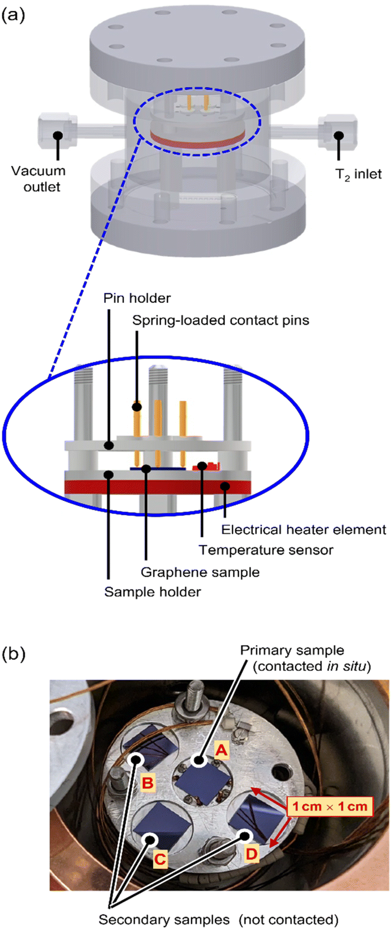 | ||
| Fig. 1 Experimental setup of the tritium loading-chamber. (a) 3D-view of technical drawing of the loading chamber, and cross-section view of the contacted and heated sample holder. (b) Sample holder with 4 graphene samples, one electrically contacted (centre) and three without contacts. | ||
The stacking design allows for easy handling within a glovebox with tritium; all components are fully tritium compatible and are made from suitable materials, like stainless steel, aluminium, copper, and ceramics. Four graphene samples are placed in close proximity on a sample holder (see Fig. 1b) and are exposed to tritium simultaneously.
The centre (primary) sample is contacted directly via four spring-loaded contacts (PTR Hartmann, Werne, Germany), which are used for the measurement of the graphene sheet resistance via the van der Pauw method.24 The sheet resistance measurements are conducted using a DAQ6150 with a 7709-matrix switching card (both from Keithley, Cleveland, USA). In order to characterize the temperature dependence of the graphene sheet resistance, an electrical heater (Thermocoax, Heidelberg, Germany) and a temperature sensor (Allectra, Schönfliess b. Berlin, Germany) are installed close to the sample.
The secondary samples can be used for, e.g., (destructive) activity determination measurements to assess the adsorbed activity before further handling of the samples.
2.3 Cold tritium plasma
In general, for the hydrogenation of graphene, either the hydrogen or the graphene has to be chemically activated.22 In contrast, for the tritiation process utilised during this study self-radiolysis of tritium has been taken advantage of. The tritium loading gas mixture was provided via the TRIHYDE facility37,38 of the Tritium Laboratory Karlsruhe (TLK) and consisted of 97.2% T2 with the remaining 2.8% being mainly HT and DT. The pressure in the loading chamber was about 400 mbar during the exposure. Given the chamber volume of about 0.2 L, this corresponds to a total activity of 7.6 × 10¹² Bq.Hydrogen atoms and ions can either reflect from, adsorb to, or penetrate through the graphene lattice. Most studies describe atom↔graphene interactions, but Despiau-Pujo et al.39 argued that the energy ranges governing the graphene–surface interactions are similar for atoms and ions, and thus ions could contribute to the chemisorption process, in principle. For tritium, Nakamura et al.40 and later Wu et al.41 calculated that a significant adsorption probability for tritium atoms of 25–75% (![[p with combining macron]](https://www.rsc.org/images/entities/i_char_0070_0304.gif) ≅ 50%) can be achieved for kinetic energies between 0.4 eV and 10 eV.
≅ 50%) can be achieved for kinetic energies between 0.4 eV and 10 eV.
In addition to these non-destructive processes, (partial) destruction of the graphene surface must be considered as well; this always becomes a possibility on exposure to a hydrogen plasma. While in general such (irreversible) destruction is not desirable, Despiau-Pujo and co-workers39 discussed in their publication how one might exploit H-plasma interaction to clean, functionalize and pattern (i.e., tailor the structure and the respective properties) graphene layers in a controlled way.
According to theory,42,43 and as recently experimentally verified,44 about half of the β-decays of T2 lead to a bound state of HeT+ (see eqn (1)), while the other half yields the dissociation products He + T+ or He+ + T, with efficiency ηdec,diss ≅ 50%.14 The dissociation products exhibit kinetic energies in the range 3–13 eV;14 they quickly thermalise down to tens of meV by collisions with the gas, which is at room temperature. For initial particle energies of O (1 eV) the inelastic scattering cross-section (of H2+ or H2) is about 10−15 cm2.45 This equates to a mean free path of about one micrometre (1 μm).
When T/T+ interact with the T2-gas, further processes take place,46 such as ionization, gas phase formation of larger ion clusters (T+ → T3+ → T5+ → …), and the recombination of the ions with electrons. The secondary molecular ions dissociate, with an efficiency of ηscat,diss ≅ 5%. The resulting Tn+ species receive between 0 eV and 15 eV of kinetic energy, peaking at about 8 eV.47 The calculation of the rate of ion generation with respect to initial β-decay electrons is complex but can be obtained, in principle, by Monte-Carlo methods.48
Note that most scattering partners (T2vs. T, T+, T2+, T3+, …) are of similar mass; thus, in every collision the particle loses on average less than 50% of its kinetic energy: about four to five scattering steps are required to drop the kinetic energy to below the threshold for absorption. Based on this, the volume above the 1 cm2 graphene sample, in which atoms/ions are generated with sufficiently low energy for tritium chemisorption at the surface, is estimated to be about 1 cm × 1 cm × (5 × 1) μm.
Here we like to point out that, at present we do not report accurate calculations of ion/atom fluxes onto the graphene film. We only estimate that in principle tritium ions/atoms have been produced in sufficient quantity in the energy range of interest, to provide significant tritium adsorption during the exposure time. At the same time, one will encounter a fraction of the ions/atoms whose energies still remain sufficiently high to be able to introduce damages to the graphene layer.
2.4 Measurement methodology
Due to the radioactive and volatile nature of tritium, many considerations must be made regarding regulatory requirements, safety, and contamination of the equipment. This severely limits the choice of possible characterization measurements. In contrast to most experiments with hydrogen, most steps of a tritium experiment are time-consuming and laborious. For example, in order to extract the samples from a tritium loading chamber, the chamber needs to be evacuated for at least a few days to minimize contamination of the surrounding glove box.Therefore, for experiments with tritium, it is essential to incorporate at least one in situ characterization method, besides a range of ex situ analysis tools.
In this work, in situ, real-time sheet resistance monitoring was utilised, and ex situ Raman characterization measurements, in combination with thermal annealing in a tritium-compatible oven, were used to investigate the nature of graphene defects introduced by its exposure to tritium. Finally, total sample activity determination helped in the evaluation of the actual tritium coverage; unfortunately, this latter measurement is destructive.
Also, it has to be stressed that using sheet resistance measurements alone, it is not possible to distinguish between the types of defects introduced to the graphene layer. Two main types of defects in graphene are relevant to this work, namely vacancy- and sp3-type defects. In the literature, three main methods are employed to distinguish between these defect types, as outlined below.
The released activity is measured using a proven TLK setup. In short, the exhaust from the oven – mostly in the form of T2 and HTO – passes through an oxidising CuO-wire bed, and then through a water bubbler, where all tritiated species are retained. The content of the water bubbler is then used to determine the total activity released during the sample heating, via liquid scintillation counting. This can also provide additional information about the nature of the C↔T interaction.
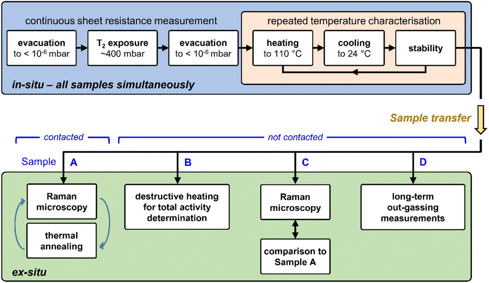 | ||
| Fig. 2 Measurement methodology for tritium-exposed graphene samples. Top – exposure of sample to tritium, followed by repeated heating cycles (monitored in situ by resistance measurement); bottom – ex situ characterisation measurements. For details, see text. | ||
3. Results and discussion
In the following presentation of results and their discussion, we are guided by a particular hypothesis, and we are looking into observations in its favour, or against it. The hypothesis is:“We can tritiate a graphene lattice (i.e., forming covalent C–T bonds) by exposing it to an atmosphere of almost pure T2 gas, at a pressure of 400 mbar”.
3.1 In situ sheet resistance measurements
During the whole tritiation process the sheet resistance, Rs, was continuously monitored; these data are shown in Fig. 3 from shortly before the inlet of tritium, and throughout the exposure to tritium, at an activity density of 3.8 × 10¹⁰ Bq cm−3 (at 400 mbar). | ||
| Fig. 3 Change of graphene sheet resistance, Rs, during tritium exposure. (A) – Initial increase of Rs when the loading chamber is filled with tritium. (B) – Plateau reached for Rs after ∼50 h of tritium exposure. (C) – Full temporal evolution of Rs during tritium exposure (orange line = generalized logistic fit to the data). | ||
In panel (A) the initial increase of the sheet resistance upon inlet of the tritiated gas mixture into the loading chamber is shown. Within just a few min, the sheet resistance of the graphene sheet increases from Rs = (551 ± 2) Ω □−1 to Rs = (5830 ± 5) Ω □−1, reaching a local maximum. In the following 1.5 h, the sheet resistance initially decreases slightly, but continues to increase again thereafter. The increase follows approximately a logistic function.53
The data for the complete measurement period is shown in Fig. 3C, together with the fit to the logistic function (orange trace); the expression for the generalised logistic function is included in the figure. The function parameters include the logistic growth rate, k; the function's midpoint time, γ; and a parameter δ which affects the shape of the growth curve (such as, e.g., the proportion of the final size at which the inflexion point occurs). The numerical values for the associated fit shown in the figure were k = 0.1125(6) h−1, γ = 20.78(1) h, and δ = 1.228(3), respectively.
Here we like to point out that the use of generalized logistic functions has been proposed, and this approach is being applied as a common chemical kinetic analysis method.54,55 As such, they describe a behaviour in which a chemical process starts from a base value, increases exponentially and ends in saturation. Indeed, such behaviour is observed in our tritiation experiment, and thus the use of a logistic function to fit the data seems an obvious choice. But one also should keep in mind that at present no complete, analytical model for the plasma evolution of radioactive tritium associated with chemisorption of tritium on graphene exists. Therefore, the description via the logistic function remains phenomenological, and no link between the fit values and the underlying radio-chemical kinetics is immediately obvious.
After an exposure time of about 55 h, the surface resistance reaches a plateau at about R∞s ≅ 129 × 103 Ω □−1, corresponding to a total relative resistivity increase by a factor of ∼250. This plateau is shown in Fig. 3B. It should be noted that the setup used for these measurements can measure resistances up to O (106 Ω), with the measured value well below the instrumental limit.
Son et al.26 cross-calibrated their graphene sheet resistance measurement against XPS-measurements, in which they could quantify the resistivity for two hydrogenation coverage values. As mentioned earlier, no XPS system was available to us. While direct comparison between hydrogenation and tritiation data is not possible at present, at least one may arrive at a crude estimate the coverage. Thus, comparing their hydrogenation results (increase of Rs by a factor of 170.9 for ηH = 12%) to our increase in Rs, the latter would correspond to a significant tritium coverage of about ηT ≈ 10–20%.
The causes of the decrease of Rs after 5 min of exposure, as well as the three spikes in Rs visible in Fig. 3C – after 17 h, 20 h, and 22 h of tritium exposure, respectively – are not yet understood and are subject to ongoing investigations.
Speculating, the spikes could have been caused by different effects. These include, for example, vibrations from the surrounding laboratory equipment disturbing the measurement, or a shift of the Fermi level/opening of the bandgap during prolonged tritium exposure, similar to previous results with hydrogen plasmas.23,26 Regardless, the general behaviour of Rs is a loading curve comparable to previously-reported loading with hydrogen.25
All observations combined clearly demonstrate that there is an interaction between the atoms/ions of the cold tritium plasma and the graphene sheet, which leads to an alteration of the graphene surface, and not to its complete disintegration.
3.2 Ex situ Raman spectroscopy and thermal annealing of tritium exposed samples
Raman spectra of graphene samples were recorded for five different conditions: (i) before tritium exposure, (ii) after tritium exposure, and (iii–v) after repeated thermal annealing at different temperatures in an Ar-atmosphere; representative Raman spectra are shown in Fig. 4A.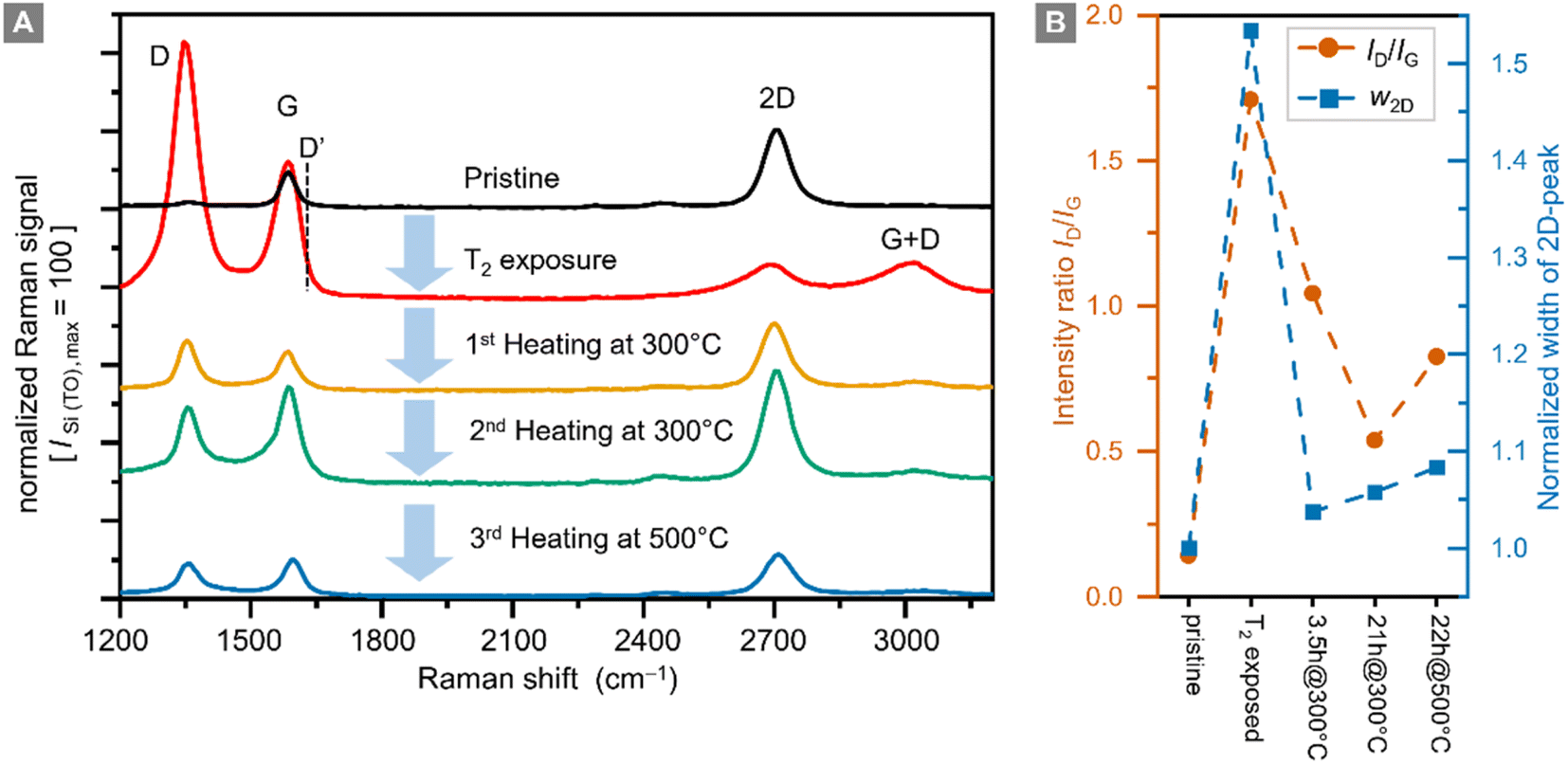 | ||
| Fig. 4 Raman spectra of a graphene sample (A), and intensity ratio ID/IG and normalized (w2D-pristine = 1) width of the 2D-peak w2D (B) prior to tritium exposure (pristine), post-tritium exposure, and after heating the post-tritium-exposure sample: 1st for 3.5 h at 300 °C, 2nd for 21 h at 300 °C, and 3rd for 22 h at 500 °C. Raman spectra are shown with a fixed offset for clarity. Key Raman spectral features are annotated. | ||
In pristine graphene the dominant features are the Raman G-band (at ∼1580 cm−1) and the Raman 2D-band (at ∼2700 cm−1).29 Both bands are associated with phonon modes without the presence of any kind of defect or disorder.56 The intensity ratio IG/I2D < 1 of the G-peak and the 2D-peak is one indicator for high-quality graphene.
In defective graphene, several other Raman bands appear in the spectra. For the study of hydrogenated (tritiated) graphene the D-band (at ∼1340 cm−1) is the most important feature.22 In addition, the D′-band (at ∼1620 cm−1) can be used to distinguish between sp3-type and vacancy-type defects.32,57 However, with our current Raman setup, we cannot resolve the D′-band; it is completely overlapped by the G-band.
For future investigations, the setup will be upgraded to higher spectral resolution. Nevertheless, the small D-peak intensity and the intensity ratio ID/IG < 0.1 confirm the high quality of the sample before tritium exposure (see the data in Fig. 4B). This is also demonstrated by the spatial homogeneity in the Raman map of the sample (see ESI S4†).
In addition, the intensity ratio ID/IG is also important because it is related to the defect density of a graphene film.30,58 In this context it should be noted that the D-peak intensity is not monotonic with respect to the defect density. When functionalization levels are very high, the ID/IG ratio reaches a maximum and then decreases. In this situation, it is helpful to use other measures to track hydrogenation and dehydrogenation processes.
After exposure to tritium the intensity of the 2D-peak is significantly reduced, while the G-peak intensity increases, resulting in an intensity ratio IG/I2D = 4.8. In addition, the D-peak intensity increases by a factor of ∼70, becoming the dominant Raman band. The intensity ratio ID/IG = 1.7 indicates a significant increase in the defect density. In hydrogenated graphene ID/IG = 0.8 ⇔ ηH = 12% and ID/IG = 2.18 ⇔ ηH = 15%,26 thus implicating – by analogy – a tritium coverage of ηT ≈ 12–14% for our sample. This is in reasonable agreement with the estimate obtained from the sheet resistance measurement (ηT ≈ 10–20%, see Section 3.1).
As stated earlier, heating the tritium-exposed samples might provide indications whether changes caused by tritium exposure are reversible. For this, the sample was placed inside a pipe oven at 300 °C for 3.5 h. Prior to this 1st heating, the oven was flushed with “wet” Argon gas (flowing through a water wash bottle the Argon gas saturates with water vapor) to prevent oxidation of the graphene layer during heating. In the process, heat is transferred from the hot, wet Argon gas to the graphene sample. Here it should be pointed out that the gas and sample temperatures are not measured directly but are lower than the nominal temperature of the ceramic tube of the pipe-oven. Note also that, during this external, thermal annealing of the samples Ar and H2O are present.
While the ID/IG ratio decreases during this heating from ID/IG = 1.7 to ID/IG = 1.0, the D-peak does not disappear completely. The 2D-peak intensity is also mostly recovered, reaching ∼83% of the original value of the pristine sample, with an intensity ratio IG/I2D = 0.6. Both observations combined show that the defect density is reduced; in other words, the graphene sample has recovered much of its original properties.
Cha et al.52 have observed a similar, partial reversibility in their hydrogenation experiments, after exposure to a hydrogen plasma with average energies of up to ∼5.35 eV; they concluded that, the ion energies within the plasma should be between 2.5 and 3.45 eV for damage-free hydrogenation of graphene. In this context theoretical studies showed that, vacancy defects in graphene form when the energy ranges from 5 eV to 12 eV.59–62 In a slightly different approach, Chen et al.50 demonstrated “self-healing” of graphene after Ar+-ion bombardment by thermal annealing. In their study, the reduction of the ID/IG ratio is even more pronounced, with a minimal value of about ID/IG = 0.25, after annealing at 800 °C. However, the relative width of the 2D-peak is increasing significantly (factor >2) when the annealing temperature exceeds 300 °C. This indicates a graphene layer whose quality has worsened.
In the experimental section we discussed that the mechanism of producing and cooling the ions down to energies which are compatible with tritium chemisorption onto graphene. Inevitably, a small quantity of ions in the higher energy range are still present. Thus, we expect that the resulting modification of the graphene is in part reversible (T-uptake) and in part irreversible (defect generation).
At similar intensity ratios in comparison to those of Chen et al.,50 namely ID/IG ≈ 0.5, we only observe an increase of the 2D-peak width by a factor of ∼1.05, after thermal annealing for a total of 24 h at 300 °C (Fig. 4B). Thus, the quality of the graphene layer is better after the combination of ‘tritium exposure + thermal annealing’ compared to the aforementioned ‘Ar+-ion bombardment plus thermal annealing’ of hydrogenated graphene. These observations indicate that the change in the Raman spectra seen after thermal annealing exceed the magnitude of the expected effects if self-healing were the only mechanism in play. This supports our hypothesis that we have a significant tritiation effect.
It should also be noted that complete healing of a graphene film was observed in the presence of a hydrocarbon gas,51 which however was not present in our annealing oven. In our sample, even after successive thermal annealing for 21 h, the D-peak remains elevated at ID/IG = 0.53, suggesting that the quality of the graphene film has decreased permanently.
In a final step, the sample was annealed for 20 h at 500 °C. During this process most of the graphene film was destroyed, and the remaining parts had an increased ratio ID/IG = 0.83, with increased D-peak intensity. It is therefore clear that with our heating setup graphene is severely damaged at 500 °C.
3.3 Total activity on tritium-exposed samples
As described in the experimental section, the setup for thermal annealing of the samples captures the released tritium while annealing, and the released activity can be quantified using liquid scintillation counting (LSC). The results from the LSC are summarized in Table 1. During each of the three thermal annealing periods of the primary sample, several MBq of activity were released.| Medium | Heating temperature (°C) | Heating duration (h) | Released activity (106 Bq) |
|---|---|---|---|
| Primary sample (contacted) | |||
| Ar + H2O | 300 | 3.5 | 8.0 ± 1.6 |
| Ar + H2O | 300 | 21 | 5.0 ± 1.0 |
| Ar + H2O | 500 | 22 | 6.5 ± 1.3 |
| ∑ = 19.5 ± 3.9 | |||
![[thin space (1/6-em)]](https://www.rsc.org/images/entities/char_2009.gif) |
|||
| Secondary sample (non-contacted) | |||
| Air | 1400 | 5 | 19.0 ± 4.0 |
At this point, it should be stressed that the above indirect methodology for the determination of the sample activity is less than ideal. For quite a few years now beta-induced X-ray spectrometry (BIXS) is being exploited instead for activity monitoring of a gaseous tritium sources or tritium-loaded surfaces; the idea goes back more than two decades.63 The method is based on the measurement of characteristic and bremsstrahlung X-rays, induced by β-electrons from the decay of tritium in the materials. For gaseous samples BIXS measurements are only sensitive to the activity content and are not influenced by the sampling (gas) mixture, as long as the pressure is low enough to avoid significant self-adsorption of the β-electrons in the sample.
More recently, compact BIXS devices have been designed and tested, that offer convenient integration into any tritium processing/monitoring facility.64 Unfortunately, no such device was available during these tritium-loading experiments, and even if one had been at hand, our rather rudimentary setup would not have had the means to accommodate it. Therefore, the approach outlined earlier in this section had to suffice, in conjunction with literature values for hydrogen coverage.
3.4 Raman maps
Two different lateral scans were conducted on the primary (contacted) tritiated sample: (i) a low spatial resolution (LSR) scan of the full sample (1 cm × 1 cm), with the step size ΔS = 62.5 μm; and (ii) a high spatial resolution (HSR) scan of a central region on the samples, with the step size ΔS = 5 μm. Different peak and peak-ratio maps from these scans are shown in Fig. 5.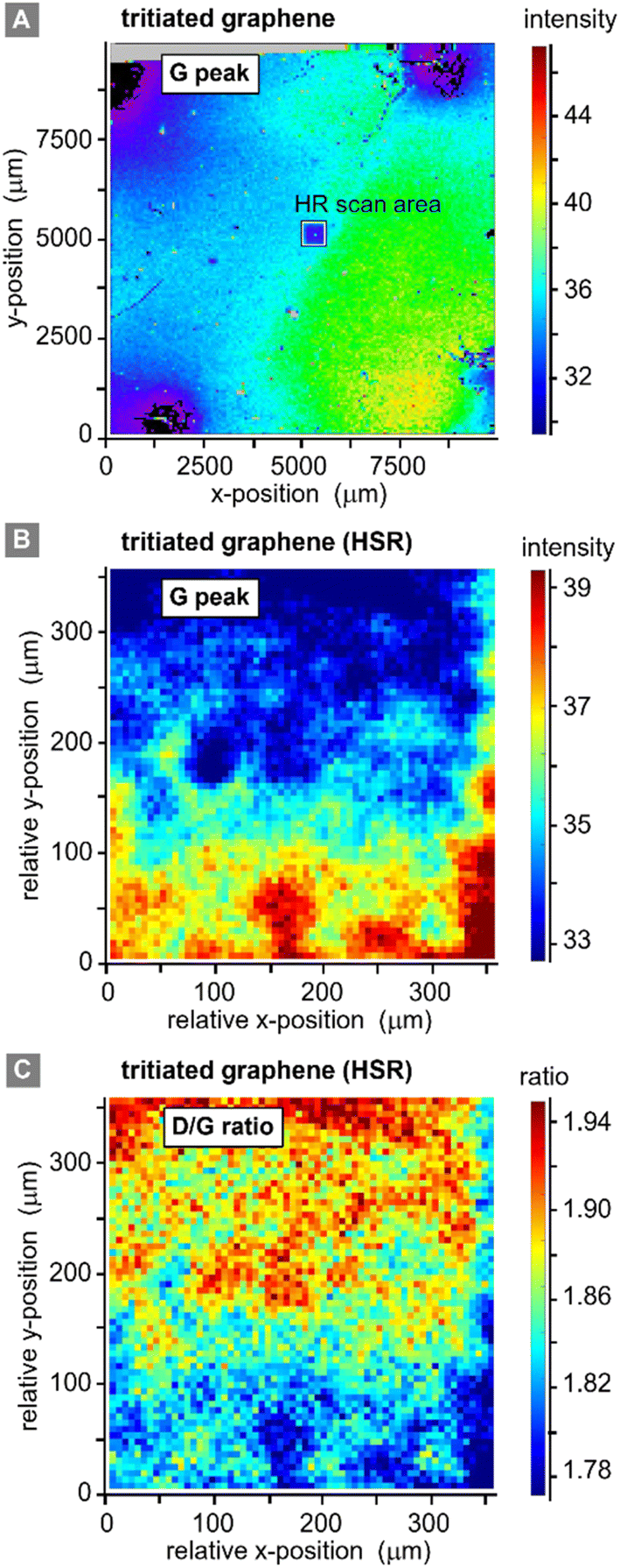 | ||
| Fig. 5 Raman spectroscopic maps of a graphene-on-SiO2/Si sample (Graphenea). (A) Raman map of the graphene G-peak signal, for the full 10 × 10 mm2 sample, post-tritium exposure; step size ΔS = 62.5 μm. (B) Raman map of the graphene G-peak signal, for a 350 × 350 μm2 sample section, post-tritium exposure; step size ΔS = 5 μm. (C) Graphene D/G Raman peak ratio map, post-tritium exposure; step size ΔS = 5 μm. Note: HSR = high spatial resolution. | ||
Equivalent scans of pristine graphene (not shown here) do not add additional information, since with our spatial resolution of ∼7 μm (ref. 32) the pristine samples look very homogenous with a relative standard deviation of the G-peak intensity of only 0.1% on an area of 300 μm × 300 μm. However, for completeness they are provided in the ESI S4.†
The LSR scan post-tritium exposure (Fig. 5A) reveals some structures on the scale of up to several 100 μm:
First, the “black” regions (mainly background signal, associated with sample fluorescence and/or instrument-internal effects) are severely damaged and have nearly no graphene left on them. These regions correspond to the positions of the spring-loaded contact pins. From HSR scans (not included here) it was evident that the contact pins had moved on the graphene surface, either during the initial contacting, vibrations from surrounding vacuum pumps, due to thermal expansion during the in situ heating of the sample, or when demounting the sample.
Second, a radial dependence of the G-peak intensities surrounding the points of contact is observed. This could be caused by shadowing of the main gas volume by the pin-holder, or by some electro-chemical effects induced by the measurement current which is supplied through the contact pins.
Third, the G-peak intensity is reduced in the region of the HSR scan (which was actually made before the LSR scan); this implies laser-induced or laser-accelerated effects. Their influence is of the order 2–3%, relative to the initial value; the intensities stabilise after 10 h of continuous laser exposure. Therefore, this does not significantly affect our working hypothesis of stable chemisorption of tritium.
Last, the changes associated with the tritium exposure (Fig. 4A above) – represented by the G-peak intensity in Fig. 5A – are distributed smoothly over the sample surface, with a slight spatial gradient.
From these observations, we conclude that, apart from the points of contact, the graphene film is still covering the whole sample, and there is no large-scale disintegration. The Raman map from the HSR scan (Fig. 5B and C) reveals some substructures on the scale of about 10–20 μm, evident by the intensity changes in the map, which could correspond to graphene flake borders. However, overall, the spectral changes are rather moderate (and gradual), with a relative standard deviation of <7% for the G-peak intensity and <5% for the ID/IG ratio.
4. Conclusions
For the first time, graphene was exposed to tritium gas in a controlled environment, with in situ real-time monitoring of the graphene sheet resistance, and subsequent post-exposure ex situ sample characterisation. These studies confirmed our working hypothesis that the cold-plasma (via self-radiolysis) exposure leads to chemisorption of tritium atoms to the graphene lattice; this is supported by the following findings.As a first observation, we report that the sheet resistance develops according to a logistic-growth function during tritium exposure, reaching a plateau after about 55 h. In the course of the tritiation process the temperature dependence of the resistance changes, indicating a transition from metallic transport characteristics to insulator-like transport characteristics, as reported in studies with hydrogenated graphene.26 Thus, this strongly indicates chemisorption of tritium to the graphene surface.
Second, using ex situ Raman microscopy, we confirmed that the change in the Raman spectra after tritium exposure is comparable to that observed in hydrogen-loading experiments carried out by other groups.26,52 Furthermore, the spectral changes are mostly homogeneous, with only slight variations over the whole area of the 1 cm × 1 cm graphene film.
Third, the Raman spectra recorded after stepwise ex situ heating of the samples show that the effect of the tritiation is partially reversible. The 2D-peak and G-peak intensity, and width, can be recovered almost completely, while the D-peak remains at an elevated level resulting in an increased intensity ratio of ID/IG = 0.53. This suggests that the graphene film was at least partially tritiated (sp3-type defects associated with C–T bonds). At the same time, the elevated D-peak implies defects, which cannot be repaired by thermal annealing (e.g., vacancy-type defects). Therefore, we conclude that, both sp3-type and vacancy-type defects are present after exposure to tritium, with reversible sp3-type defects being dominant.
These observations are compatible with the coarse estimation of possible tritium chemisorption via a mechanism in which atoms and ions of eV-scale energy are generated, likely by dissociation after secondary ionization in collision with β-electrons, followed by collisional cooling in the gas over a distance of just a few micrometres.
Overall, we have demonstrated that, our rather simple experimental arrangement allows for significant tritiation of a macroscopic graphene surface, and thereby proving the initial working hypothesis to be correct.
While recent theoretical considerations suggest that tritiated graphene may not present a way out of the energy broadening from molecular effects in the β-electron spectrum, tritium – which is immobilised onto a surface and stable at room temperature – may still offer many practical benefits. In particular, it allows for the preparation of solid-state tritium sources, which may facilitate proof-of-principle studies of modern electron detection concepts.
Damages introduced to graphene are per se not avoidable using our self-radiolysis cold-plasma approach. Other techniques, providing atoms and ions by thermal dissociation or RF plasma sources, might provide more controllable particle energies, and thus be gentler with regard to potential surface damage. Furthermore, any large-scale carbon–tritium electron source, as for example planned for PTOLEMY,16 will inevitably be confronted with high fluxes of ions possessing kinetic energies Ekin > 5 eV originating from β-decay, or secondary ionization. This poses the challenge of possible deterioration of the substrate's spatial homogeneity, and thus the energy smearing of β-decay electrons is expected to alter over time.
After this successful first step, we plan to continue to study the mechanism of this tritiation method, by exploring different loading pressures and compositions, and applying improved analytical techniques.
In particular, we plan to utilise different graphene samples, custom-contacted by Graphenea with gold-layer pads, to avoid having to use the spring-loaded contacts employed during this work. This will eliminate the poor reproducibility of establishing electrical contact. In addition, appropriate contact patterns might allow for measurement options, apart from van der Pauw monitoring, using the graphene sample in a sensory capacity, like in the form of graphene field-effect transistor (gFET) sensors, which are found in an increased number of applications.65
In the longer term, we intend to redesign our loading cell in such a way that access for additional monitoring tools is provided, including potentially in situ Raman spectroscopy with spatial resolution.
Finally, we aim at investigating the applicability of the tritium–graphene system in tritium processing, such as, e.g., isotope separation.11
Author contributions
Conceptualization – M. S. and H. H. T. formulated the ideas for this research programme, and its goals and directions. Formal Analysis – G. Z. carried out the majority of the data analysis and visualization of data. Funding acquisition & project administration – M. S. and B. B. administered the overall project and secured its finances. Investigation – G. Z. and D. D. B. carried out the bulk of the experimental work, assisted in parts of the project by P. W. (van-der-Pauw setup and measurements); M. A. (initial proof-of-principle work on hydrogenation of graphene, using van-der-Pauw sensing); and A. L. (contacting of graphene for van-der-Pauw measurements). Methodology – G. Z., D. D. B. and M. S. developed the ideas for the series of complementary measurement methodologies to reach the intended goals. Resources – S. N. was in charge of the loading-stage chamber design and, gas and sample handling in the TriHyDe facility, and N. T. was responsible for the sample heating and activity determination procedures. Software – G. Z. and J. D. developed specific software scripts to evaluate and display Raman raster scan maps, in association with our data acquisition and evaluation software suite. Supervision – H. H. T., M. S. and K. V. were responsible for overall running of the experiments, and the supervision of the research students. Writing (original draft) – G. Z., M. S. and H. H. T. prepared the draft concept for this publication, and wrote the initial manuscript. Writing (review & editing) – all authors contributed to revising and editing of the manuscript.Conflicts of interest
There are no conflicts to declare.Acknowledgements
G. Z. acknowledges his PhD fellowship, provided by the Karlsruhe School of Elementary Particle and Astroparticle Physics: Science and Technology (KSETA); and D. D. B. gratefully acknowledges a grant contribution for a research visit, provided by the KIT Center Elementary Particle and Astroparticle Physics (KCETA). General financial support for this CRM/graphene project has been provided by KCETA. M. S. and K. V. acknowledge seed funding by the KIT Future Fields programme through the “ELECTRON” project. Finally, we would like to thank L. Schlüter for diligently proof-reading our manuscript.References
- K. S. Novoselov, A. K. Geim, S. V. Morozov, D. Jiang, Y. Zhang and S. V. Dubonos, et al., Electric field effect in atomically thin carbon films, Science, 2004, 306, 666–669, DOI:10.1126/science.1102896.
- A. Castellanos-Gomez, M. Wojtaszek, N. T. Arramel, N. Tombros and B. J. van Wees, Reversible hydrogenation and bandgap opening of graphene and graphite surfaces probed by scanning tunneling spectroscopy, Small, 2012, 8, 1607–1613, DOI:10.1002/smll.201101908.
- Y. Fei, S. Fang and Y. H. Hu, Synthesis, properties and potential applications of hydrogenated graphene, Chem. Eng. J., 2020, 397, 125408, DOI:10.1016/j.cej.2020.125408.
- D. C. Elias, R. R. Nair, T. M. G. Mohiuddin, S. V. Morozov, P. Blake and M. P. Halsall, et al., Control of graphene's properties by reversible hydrogenation: evidence for graphane, Science, 2009, 323, 610–613, DOI:10.1126/science.1167130.
- A. A. Dzhurakhalov and F. M. Peeters, Structure and energetics of hydrogen chemisorbed on a single graphene layer to produce graphane, Carbon, 2011, 49, 3258–3266, DOI:10.1016/j.carbon.2011.03.052.
- A. Felten, D. McManus, C. Rice, L. Nittler, J.-J. Pireaux and C. Casiraghi, Insight into hydrogenation of graphene: Effect of hydrogen plasma chemistry, Appl. Phys. Lett., 2014, 105, 183104, DOI:10.1063/1.4901226.
- M. M. S. Abdelnabi, C. Izzo, E. Blundo, M. G. Betti, M. Sbroscia and G. Di Bella, et al., Deuterium Adsorption on Free-Standing Graphene, Nanomaterials, 2021, 11, 130, DOI:10.3390/nano11010130.
- F. C. Bocquet, R. Bisson, J. M. Themlin, J.-M. Layet and T. Angot, Deuterium adsorption on (and desorption from) SiC(0 0 0 1)-(3×3), 3×3 R30°, 63×63 R30° and quasi-free-standing graphene obtained by hydrogen intercalation, J. Phys. D: Appl. Phys., 2014, 47, 094014, DOI:10.1088/0022-3727/47/9/094014.
- M. Rethinasabapathy, S. M. Ghoreishian, S.-K. Hwang, Y.-K. Han, C. Roh and Y. S. Huh, Recent progress in functional nanomaterials towards the storage, separation, and removal of tritium, Adv. Mater., 2023, 35, 2301589, DOI:10.1002/adma.202301589.
- M. Zhang, K. Deng, F. Wei, X. Wu, L. Du and W. Liu, Adsorption and Desorption of Tritium on/from Nuclear Graphite, ACS Omega, 2022, 7, 752–760, DOI:10.1021/acsomega.1c05395.
- M. Lozada-Hidalgo, S. Zhang, S. Hu, A. Esfandiar, I. V. Grigorieva and A. K. Geim, Scalable and efficient separation of hydrogen isotopes using graphene-based electrochemical pumping, Nat. Commun., 2017, 8, 15215, DOI:10.1038/ncomms15215.
- M. Aker, M. Balzer, D. Batzler, A. Beglarian, J. Behrens and A. Berlev, et al., KATRIN: status and prospects for the neutrino mass and beyond, J. Phys. G: Nucl. Part. Phys., 2022, 49, 100501, DOI:10.1088/1361-6471/ac834e.
- M. Aker, A. Beglarian, J. Behrens, A. Berlev, U. Besserer and B. Bieringer, et al., Direct neutrino-mass measurement with sub-electronvolt sensitivity, Nat. Phys., 2022, 18, 160–166, DOI:10.1038/s41567-021-01463-1.
- L. I. Bodine, D. S. Parno and R. G. H. Robertson, Assessment of molecular effects on neutrino mass measurements from tritium β decay, Phys. Rev. C, 2015, 91, 035505, DOI:10.1103/PhysRevC.91.035505.
- Project 8 Collaboration: A. Ashtari Esfahani, S. Böser, N. Buzinsky, M. C. Carmona-Benitez, C. Claessens, L. de Viveiro, et al., The Project 8 Neutrino Mass Experiment, in Proceedings of the US Community Study on the Future of Particle Physics (Snowmass 2021), arXiv, preprint, 2022, DOI:10.48550/arXiv.2203.07349.
- E. Baracchini, M. G. Betti, M. Biasotti, A. Bosca, F. Calle, J. Carabe-Lopez, et al., PTOLEMY: A Proposal for Thermal Relic Detection of Massive Neutrinos and Directional Detection of MeV Dark Matter, 2018, online access: http://arxiv.org/pdf/1808.01892v1 Search PubMed.
- S. Weinberg, Universal Neutrino Degeneracy, Phys. Rev., 1962, 128, 1457–1473, DOI:10.1103/PhysRev.128.1457.
- S. Betts, W. R. Blanchard, R. H. Carnevale, C. Chang, C. Chen, S. Chidzik, et al., Development of a Relic Neutrino Detection Experiment at PTOLEMY: Princeton Tritium Observatory for Light, Early-Universe, Massive-Neutrino Yield, 2013, https://arxiv.org/pdf/1307.4738 Search PubMed.
- Y. Cheipesh, V. Cheianov and A. Boyarsky, Navigating the pitfalls of relic neutrino detection, Phys. Rev. D, 2021, 104, 116004, DOI:10.1103/PhysRevD.104.116004.
- S. Nussinov and Z. Nussinov, Quantum induced broadening: A challenge for cosmic neutrino background discovery, Phys. Rev. D, 2022, 105, 043502, DOI:10.1103/PhysRevD.105.043502.
- M. M. S. Abdelnabi, E. Blundo, M. G. Betti, G. Cavoto, E. Placidi and A. Polimeni, et al., Towards free-standing graphane: atomic hydrogen and deuterium bonding to nano-porous graphene, Nanotechnology, 2021, 32, 35707, DOI:10.1088/1361-6528/abbe56.
- K. E. Whitener, Review Article: Hydrogenated graphene: A user's guide, J. Vac. Sci. Technol., A, 2018, 36, 05G401, DOI:10.1116/1.5034433.
- J. O. Sofo, A. S. Chaudhari and G. D. Barber, Graphane: A two-dimensional hydrocarbon, Phys. Rev. B: Condens. Matter Mater. Phys., 2007, 75, 53401, DOI:10.1103/PhysRevB.75.153401.
- L. J. van der Pauw, A Method of measuring specific resistivity and hall effect of discs of arbitrary shape, Philips Res. Rep., 1958, 13, 1–9 Search PubMed.
- J. Guillemette, Electronic Transport in Hydrogenated Graphene, Dissertation, McGill University, Montréal (Canada), 2014, online access: https://gervaislab.mcgill.ca/Guillemette_PhD_Thesis.pdf, accessed 23 February 2024 Search PubMed.
- J. Son, S. Lee, S. J. Kim, B. C. Park, H.-K. Lee and S. Kim, et al., Hydrogenated monolayer graphene with reversible and tunable wide band gap and its field-effect transistor, Nat. Commun., 2016, 7, 13261, DOI:10.1038/ncomms13261.
- R. Beams, L. Gustavo Cançado and L. Novotny, Raman characterization of defects and dopants in graphene, J. Condens. Matter Phys., 2015, 27, 83002, DOI:10.1088/0953-8984/27/8/083002.
- C. Casiraghi, Probing disorder and charged impurities in graphene by Raman spectroscopy, Phys. Status Solidi RRL, 2009, 3, 175–177, DOI:10.1002/pssr.200903135.
- A. C. Ferrari and D. M. Basko, Raman spectroscopy as a versatile tool for studying the properties of graphene, Nat. Nanotechnol., 2013, 8, 235–246, DOI:10.1038/nnano.2013.46.
- M. M. Lucchese, F. Stavale, E. M. Ferreira, C. Vilani, M. Moutinho and R. B. Capaz, et al., Quantifying ion-induced defects and Raman relaxation length in graphene, Carbon, 2010, 48, 1592–1597, DOI:10.1016/j.carbon.2009.12.057.
- A. J. Pollard, B. Brennan, H. Stec, B. J. Tyler, M. P. Seah and I. S. Gilmore, et al., Quantitative characterization of defect size in graphene using Raman spectroscopy, Appl. Phys. Lett., 2014, 105, 253107, DOI:10.1063/1.4905128.
- A. Eckmann, A. Felten, A. Mishchenko, L. Britnell, R. Krupke and K. S. Novoselov, et al., Probing the nature of defects in graphene by Raman spectroscopy, Nano Lett., 2012, 12, 3925–3930, DOI:10.1021/nl300901a.
- D. Diaz Barrero, G. Zeller, M. Schlösser, B. Bornschein and H. H. Telle, Versatile Confocal Raman Imaging Microscope Built from Off-the-Shelf Opto-Mechanical Components, Sensors, 2022, 22, 10013, DOI:10.3390/s222410013.
- D. Díaz Barrero, T. L. Le, S. Niemes, S. Welte, M. Schlösser and B. Bornschein, et al., Generation and Analysis of Tritium-Substituted Methane, Fusion Sci. Technol., 2023 DOI:10.1080/15361055.2023.2194235.
- Graphenea, Monolayer Graphene on 90 nm SiO2/Si, online access: https://www.graphenea.com, accessed 23 February 2024 Search PubMed.
- E. Pop, V. Varshney and A. K. Roy, Thermal properties of graphene: Fundamentals and applications, MRS Bull., 2012, 37, 1273–1281, DOI:10.1557/mrs.2012.203.
- S. Niemes, H. H. Telle, B. Bornschein, L. Fasselt, R. Größle and F. Priester, et al., Accurate Reference Gas Mixtures Containing Tritiated Molecules: Their Production and Raman-Based Analysis, Sensors, 2021, 21, 6170, DOI:10.3390/s21186170.
- S. Niemes, Calibration of a Laser-Raman-System Using Gas Samples of All Hydrogen Isotopologues for KATRIN, Dissertation, Karlsruhe Institute of Technology (KIT), 2021, DOI:10.5445/IR/1000128966.
- E. Despiau-Pujo, A. Davydova, G. Cunge and D. B. Graves, Hydrogen Plasmas Processing of Graphene Surfaces, Plasma Chem. Plasma Process., 2016, 36, 213–229, DOI:10.1007/s11090-015-9683-0.
- H. Nakamura, A. Takayama and A. Ito, Molecular Dynamics Simulation of Hydrogen Isotope Injection into Graphene, Contrib. Plasma Phys., 2008, 48, 265–269, DOI:10.1002/ctpp.200810046.
- E. Wu, C. Schneider, R. Walz and J. Park, Adsorption of hydrogen isotopes on graphene, Nucl. Eng. Technol., 2022, 54, 4022–4029, DOI:10.1016/j.net.2022.06.014.
- S. Jonsell, A. Saenz and P. Froelich, Neutrino-mass determination from tritium beta-decay: Corrections to and prospects of experimental verification of the final-state spectrum, Phys. Rev. C, 1999, 60, 34601, DOI:10.1103/PhysRevC.60.034601.
- A. Saenz, S. Jonsell and P. Froelich, Improved Molecular Final-State Distribution of HeT+ for the beta-Decay Process of T2, Phys. Rev. Lett., 2000, 84, 242–245, DOI:10.1103/PhysRevLett.84.242.
- Y.-T. Lin, T. H. Burritt, C. Claessens, G. Holman, M. Kallander and E. Machado, et al., Beta Decay of Molecular Tritium, Phys. Rev. Lett., 2020, 124, 222502, DOI:10.1103/PhysRevLett.124.222502.
- T. Tabata and T. Shirai, Analytic Cross Sections for Collisions of H+, H2+, H3+, H, H2 and H− with Hydrogen Molecules, At. Data Nucl. Data Tables, 2000, 76, 1–25, DOI:10.1006/adnd.2000.0835.
- M. Klein, Tritium Ions in KATRIN: Blocking, Removal and Detection, Dissertation, Karlsruhe Institute of Technology (KIT), 2018, DOI:10.5445/IR/1000093526.
- G. H. Dunn and L. J. Kieffer, Dissociative Ionization of H2: A Study of Angular Distributions and Energy Distributions of Resultant Fast Protons, Phys. Rev., 1963, 132, 2109–2117, DOI:10.1103/PhysRev.132.2109.
- J. Kellerer and F. Spanier, Monte Carlo Simulations of the Electron − Gas Interactions in the KATRIN Experiment, J. Instrum., 2022, 17, P06029, DOI:10.1088/1748-0221/17/06/P06029.
- G. Speranza, L. Minati and M. Anderle, The C1s core line in irradiated graphite, J. Appl. Phys., 2007, 102, 043504, DOI:10.1063/1.2769332.
- J. Chen, T. Shi, T. Cai, T. Xu, L. Sun and X. Wu, et al., Self-healing of defected graphene, Appl. Phys. Lett., 2013, 102, 103107, DOI:10.1063/1.4795292.
- V. López, R. S. Sundaram, C. Gómez-Navarro, D. Olea, M. Burghard and J. Gómez-Herrero, et al., Chemical Vapor Deposition Repair of Graphene Oxide: A Route to Highly-Conductive Graphene Monolayers, Adv. Mater., 2009, 21, 4683–4686, DOI:10.1002/adma.200901582.
- J. Cha, H. Choi and J. Hong, Damage-free hydrogenation of graphene via ion energy control in plasma, Appl. Phys. Express, 2022, 15, 015002, DOI:10.35848/1882-0786/ac4204.
- F. J. Richards, A Flexible Growth Function for Empirical Use, J. Exp. Bot., 1959, 10, 290–301 CrossRef . Online access: https://www.jstor.org/stable/23686557.
- I. Avramov and J. Šesták, Generalized kinetics of overall phase transition explicit to crystallization, J. Therm. Anal. Calorim., 2014, 118, 1715–1720, DOI:10.1007/s10973-014-4144-1.
- A. K. Burnham, Use and misuse of logistic equations for modeling chemical kinetics, J. Therm. Anal. Calorim., 2017, 127, 1107–1116, DOI:10.1007/s10973-015-4879-3.
- A. C. Ferrari, J. C. Meyer, V. Scardaci, C. Casiraghi, M. Lazzeri and F. Mauri, et al., Raman Spectrum of Graphene and Graphene Layers, Phys. Rev. Lett., 2006, 97, 187401, DOI:10.1103/PhysRevLett.97.187401.
- A. Eckmann, A. Felten, I. Verzhbitskiy, R. Davey and C. Casiraghi, Raman Study on Defective Graphene: Effect of the Excitation Energy, Type, and Amount of Defects, Phys. Rev. B: Condens. Matter Mater. Phys., 2013, 88, 035426, DOI:10.1103/PhysRevB.88.035426.
- E. H. Martins Ferreira, M. V. O. Moutinho, F. Stavale, M. M. Lucchese, R. B. Capaz and C. A. Achete, et al., Evolution of the Raman spectra from single-, few-, and many-layer graphene with increasing disorder, Phys. Rev. B: Condens. Matter Mater. Phys., 2010, 82, 125429, DOI:10.1103/PhysRevB.82.125429.
- A. V. Krasheninnikov, P. O. Lehtinen, A. S. Foster and R. M. Nieminen, Bending the rules: Contrasting vacancy energetics and migration in graphite and carbon nanotubes, Chem. Phys. Lett., 2006, 418, 132–136, DOI:10.1016/j.cplett.2005.10.106.
- A. A. El-Barbary, R. H. Telling, C. P. Ewels, M. I. Heggie and P. R. Briddon, Structure and energetics of the vacancy in graphite, Phys. Rev. B: Condens. Matter Mater. Phys., 2003, 68, 144107, DOI:10.1103/physrevb.68.144107.
- G.-D. Lee, C. Z. Wang, E. Yoon, N.-M. Hwang, D.-Y. Kim and K. M. Ho, Diffusion, coalescence, and reconstruction of vacancy defects in graphene layers, Phys. Rev. Lett., 2005, 95, 205501, DOI:10.1103/PhysRevLett.95.205501.
- E. Ertekin, D. C. Chrzan and M. S. Daw, Topological description of the Stone-Wales defect formation energy in carbon nanotubes and graphene, Phys. Rev. B: Condens. Matter Mater. Phys., 2009, 79, 155421, DOI:10.1103/physrevb.79.155421.
- M. Matsuyama, K. Watanabe and K. Hasegawa, Tritium assay in materials by the bremsstrahlung counting method, Fusion Eng. Des., 1998, 39–40, 929–936, DOI:10.1016/s0920-3796(98)00232-4.
- M. Röllig, S. Ebenhöch, S. Niemes, F. Priester and M. Sturm, Development of a compact tritium activity monitor and first tritium measurements, Fusion Eng. Des., 2015, 100, 177–180, DOI:10.1016/j.fusengdes.2015.05.056.
- S. Szunerits, T. Rodrigues, R. Bagale, H. Happy, R. Boukherroub and W. Knoll, Graphene-based field-effect transistors for biosensing: where is the field heading to?, Anal. Bioanal. Chem., 2024, 416, 2137–2150, DOI:10.1007/s00216-023-04760-1.
Footnote |
| † Electronic supplementary information (ESI) available: Supplement S1 – measurement protocol; supplement S2 – in situ monitoring during sample heating; supplement S3 – setup of the confocal Raman microscope; supplement S4 – Raman maps of pristine graphene. See DOI: https://doi.org/10.1039/d3na00904a |
| This journal is © The Royal Society of Chemistry 2024 |