 Open Access Article
Enhancing the stability and efficiency of carbon-based perovskite solar cell performance with ZrO2-decorated rGO nanosheets in a mesoporous TiO2 electron-transport layer†
Anjan
Kumar
 a,
M. I.
Sayyed
bc,
Anmar Ghanim
Taki
*d,
Vanessa
Valverde
e and
Eduardo
Hernández
e
aDepartment of Electronics and Communication Engineering, GLA University, Mathura-281406, India
bDepartment of Physics, Faculty of Science, Isra University, Amman 11622, Jordan
cRenewable Energy and Environmental Technology Center, University of Tabuk, Tabuk 47913, Saudi Arabia
dDepartment of Radiology & Sonar Techniques, Al-Noor University College, Nineveh, Iraq. E-mail: anmar.ghanim@alnoor.edu.iq
eFacultad Mecánica, Escuela Superior Politécnica de Chimborazo (ESPOCH), Riobamba, 060155, Ecuador
First published on 7th December 2023
Abstract
Improving the role of electron-transport layers (ETLs) in carbon-based perovskite solar cells (CPSCs) is a promising method to increase their photovoltaic efficiency. Herein, we employed rGO sheets decorated with ZrO2 nanoparticles to increase the electron transport capability of mesoporous TiO2 ETLs. We found that the rGO/ZrO2 dopant enhanced the conductivity of the ETL, reducing the charge-transfer resistance at the ETL/perovskite interface and reducing charge recombination in the corresponding CPSCs. Notably, this dopant did not effectively change the transparency of ETLs, while increasing the light-harvesting ability of their own top perovskite layer by improving the crystallinity of the perovskite layer. The rGO/ZrO2-containing ETLs produced a champion efficiency of 15.21%, while devices with a net ETL recorded a maximum efficiency of 11.88%. In addition, the modified devices showed a higher stability behavior against ambient air than the net devices, which was linked to the passivated grain boundaries of the modified perovskite layers along with the improved hydrophobicity.
Introduction
Perovskite materials with the general formula ABC3 are widely employed in solar cell applications due to their excellent optical properties as a light-harvesting layer.1,2 In earlier studies, the efficiency of perovskite-based solar cells was around 3–4%,3 which with massive efforts has been raised to 25.8% in recent state-of-the-art studies.4 In addition to the favorable efficiency reported for perovskite solar cells, the price of these devices is too high for their large-scale production, mainly due to the costs of the hole-transport materials and metal electrodes. Besides, their environmental stability is not sufficient for their commercialization.5–8 Perovskite solar cells without a hole-transport layer and carbon electrodes (HTL-free CPSCs) offer the potential for solar cells with reasonable prices and good environmental stability.9–11 In HTL-free CPSCs, carbon electrodes have two roles: as a back electrode and blocking electron carriers. Compared with state-of-the-art perovskite-based solar cells, HTL-free CPSCs have lower efficiency, and further attempts are thus needed to increase their efficiency.12 Ku et al. for the first time used carbon-based electrodes in HTL-free devices with an architecture of FTO/c-TiO2/m-TiO2/ZrO2/MAPbI3/carbon and recorded an efficiency of 6.64%.13 Rong et al. synthesized (100)-TiO2 nanosheets and used these as an ETL in HTL-free CPSCs. They raised the efficiency of HTL-free CPSCs to 10.64%.14The modification of ETL and/or engineering the interface of ETL/perovskite in CPCSs are two eligible routes to increase the performance of CPSCs.15–18 Qiang et al. doped the SnO2 ETL with lithium ions to increase the photoelectrons' lifetime and solar cell current density. The lithium-doped ETL brought them an efficiency of 10.01% for HTL-free CPSCs.19 Li et al. tailored both interfaces of ETL/perovskite and perovskite/carbon in HTL-free CPSCs. They used FAI/IPA solution for the treatment of the SnO2 ETL and also carbon electrodes. This dual interface engineering improved the light-harvesting ability of as-fabricated devices and suppressed nonradiative recombination in the HTL-free CPSCs.20 Kumar et al. treated SnO2 ETLs with yttrium fluoride material to increase the photovoltaic performance of HTL-free CPSCs. They showed that yttrium fluoride hindered the residual PbI2 in the perovskite layer, reduced the charge traps, and facilitated the charge-transfer mechanisms in a solar cell system.21 Wu et al. developed a new urea–TiCl4 solution for post-treatment of a TiO2 ETL. They showed that urea could control the TiCl4 pH, which induced the formation of the anatase TiO2 phase in the ETL. Indeed, the urea–TiCl4 treatment increased the electrical conductivity of the TiO2 ETL and shifted its conduction band energy level up to better align with the perovskite energy level, resulting in a higher electron extraction rate in the CPSCs.22 Liu et al. developed Mg-doped TiO2 to increase the efficiency of CPSCs. They found that the Mg dopant increased the electrical conductivity of the TiO2 ETL and shorted the carriers' decay time. A Mg-doped ETL was reported that induced electron extraction and reduced the charge recombination rate within CPSCs, recording an efficiency of 15.73%.23 He et al. introduced S2− ions into SnO2 ETLs using thiourea material. They showed that the S2− ions captured Pb2+ ions at the ETL/perovskite interface and reduced the trap density in the perovskite layer, resulting in an improvement in the photovoltaic properties of HTL-free CPSCs.24
Due to their good conductivity, electron affinity, and transparency, reduced graphene oxide (rGO) and its derivatives can be considered desirable candidates for improving the roles of TiO2 ETLs in HTL-free CPSCs.25–28 Nouri et al. used rGO materials to enhance the electron lifetime and charge recombination resistance in solar cells, which boosted the photovoltaic efficiency in PSCs.29 Recently, Kadhim et al. introduced rGO/Bi2O3 into the mesoporous TiO2 layer for tailoring ETLs. They showed that the modified ETLs had a higher charge extraction at the ETl/perovskite interface, which increased the solar cells' efficiency to 17.21%.30 Bagha et al. used rGO nanosheets for modifying ZnO ETLs. They found out that the rGO materials reduced interfacial resistance at the ZnO/perovskite interface and increased the PCE of PSCs.31
In the current study, for the first time, we developed a rGO/ZrO2 nanocomposite additive for a mesoporous TiO2 (mp-TiO2) precursor to increase the photovoltaic performance of HTL-free CPSCs. The rGO/ZrO2-containing mp-TiO2 layers showed higher electrical conductivity than the net mp-TiO2. In addition, the incorporation of rGO/ZrO2 in to mp-TiO2 reduced its surface roughness, resulting in an improved perovskite layer morphology and reduced surface defects. It was found that the charge interfacial resistance in as-fabricated rGO/ZrO2-containing devices was lower than that of the net devices, which facilitated charge transfer in the corresponding solar cells. The efficiency of the HTL-free CPSCs could be increased from 11.88% to 15.21% using this ETL modification. Notably, the improved perovskite crystallinity caused by rGO/ZrO2 modification increased the ambient air stability of the HTL-free CPSCs.
Experiments
Synthesis of rGO nanosheets
First, 500 mg graphite powder (99%, Alfa Aesar) and 1.5 g permanganate (99%, Merck) were added to a beaker and 25 mL sulfuric acid (98%, Merck) was poured into this while stirring in an ice bath for 6 h. The solution temperature was kept 10 °C. Then, the graphite solution was stirred at RT for 45 min. Next, 200 mL distilled water (DW) was poured into the beaker and sonicated for 2 h at RT. By the addition of sodium hydroxide (98%, Merck) solution (1 M), the pH of the suspension was controlled at 6, followed by sonication for 1 h. After that, 5 g L-ascorbic acid (99%, Merck) was poured in 50 mL DW and dropped into the graphite oxide solution at RT. This solution was stirred at 95 °C for 120 min for reduction of the graphite oxide. The obtained precipitates were filtered and washed with DW and a 1 M hydrochloric acid solution (37%, Merck) to reduce the pH to neutral. Finally, the washed precipitates were dried at 50 °C for 24 h to obtain the rGO nanosheets.Synthesis of rGO/ZrO2 nanocomposites
The rGO/ZrO2 nanocomposite was synthesized by hydrothermal method. Here, 70 mg of rGO sheets was ultrasonically dispersed in 50 mL of DW for 2 h. After that, rGO dispersion was added to a beaker containing 30 mL of 0.03 M ZrOCl2·8H2O and stirred for 30 min at RT. The final dispersion was sonicated for 2 h, and 1 mL of hydrazine hydrate was then added to it. The obtained solution was transferred into a stainless steel Teflon-lined autoclave at 185 °C for 24 h. The dark-colored material was centrifuged. The obtained material was washed with distilled water and subsequently by ethanol, followed by drying at 60 °C overnight.Device preparation
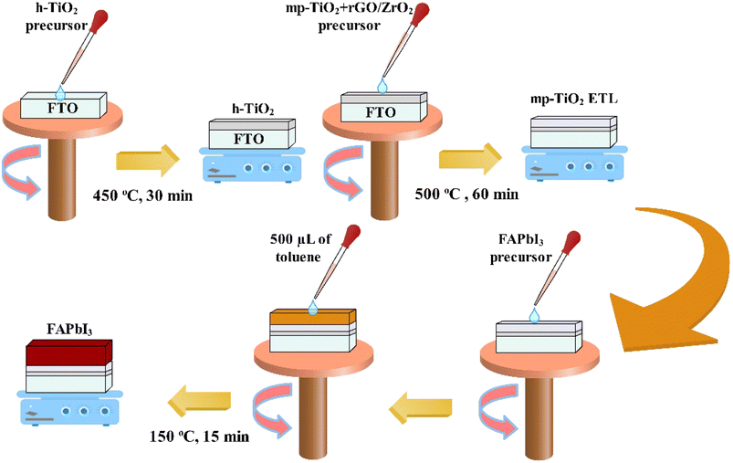
The hole-blocking titanium dioxide (h-TiO2) pre-solution was prepared by mixing 5 mL ethanol (EtOH, 99.8%, Merck) and 350 μL titanium(IV) tetra isopropoxide (TTIP, 98%, EXIR) in the presence of 35 μL hydrochloride acid (2 M) (HCl, Merck). Next, 50 μL of h-TiO2 solution was spread on the FTO substrate and spin-coated at 4000 rpm for 30 s, followed by baking at 450 °C for 30 min. Then, 500 mg of mesoporous titanium dioxide (mp-TiO2) paste (Dyesol, 25 NR paste) was poured in 4.250 mg of EtOH and stirred for 24 h at RT to prepare the mp-TiO2 precursor. To prepare the doped ETLs, 5 mg of rGO/ZrO2 or rGO materials was dispersed into 1 mL EtOH by sonication for 45 min at RT. Then, different amounts of them in varied volume ratios were added to mp-TiO2 precursors and stirred for 24 h at RT. Next, 75 μL of net or doped mp-TiO2 solutions were spin-coated on the h-TiO2 layer at a speed of 3500 rpm for 25 s, followed by baking at 500 °C for 60 min. Here FAPbI3 was used as a light-harvesting layer, and its pre-solution was prepared by dissolving 0.461 g of lead iodide (PbI2, 99.9%, Lumtec) in 769 μL of solvents of dimethyl sulfoxide (DMSO, 99.9%, Merck) and dimethylformamide (DMF, 99.8%, Merck) in a volume ratio of 1![[thin space (1/6-em)]](https://www.rsc.org/images/entities/char_2009.gif) :
:![[thin space (1/6-em)]](https://www.rsc.org/images/entities/char_2009.gif) 9, followed by stirring at 80 °C for 45 min. Then, 0.171 g of FAI (99.8%, Lumtec) and 0.27 g of MACl (99.8%, Merck) were mixed with the PbI2 precursor and sonicated for 10 min at RT. The perovskite layer was formed by spin-coating 75 μL of FAPbI3 solution over the ETLs at 5000 rpm for 30 s. Then, they were annealed at 150 °C for 15 min. During the spin-coating process, 500 μL of toluene (99.8%, Merck) was swiftly poured on to the perovskite to promote perovskite growth. Dyenamo, a DN-CP01 carbon paste, was bladed on the FAPbI3 films to fabricate carbon electrodes, followed by annealing at 70 °C for 30 min.
9, followed by stirring at 80 °C for 45 min. Then, 0.171 g of FAI (99.8%, Lumtec) and 0.27 g of MACl (99.8%, Merck) were mixed with the PbI2 precursor and sonicated for 10 min at RT. The perovskite layer was formed by spin-coating 75 μL of FAPbI3 solution over the ETLs at 5000 rpm for 30 s. Then, they were annealed at 150 °C for 15 min. During the spin-coating process, 500 μL of toluene (99.8%, Merck) was swiftly poured on to the perovskite to promote perovskite growth. Dyenamo, a DN-CP01 carbon paste, was bladed on the FAPbI3 films to fabricate carbon electrodes, followed by annealing at 70 °C for 30 min.
Characterization
A TEM Philips EM 208S instrument and Mira3 TESCAN field emission SEM instrument were employed to record the TEM and FESEM images of the samples, respectively. An AFM Vecco device was used to measure the surface roughness of the mp-TiO2 layers. An XRD Philips PW1730 X-ray diffractometer collected the XRD patterns of the rGO, ZrO2, rGO/ZrO2, and perovskite layers. A UV-VIS Thermo Biomate5 spectrophotometer was used to investigate the absorbance of the perovskite films and also the transmittance of the mp-TiO2 layers. A PL CARY ECLIPSE device recorded the photoluminescence (PL) response of the perovskite layers coated on different ETLs. To measure the PL, the samples were excited at a wavelength of 450 nm. A Keithley 2401 instrument under calibrated AM 1.5 light irradiance was used to measure the current density–voltage curves of the carbon-based HTL-free PSCs to calculate the photovoltaic performance and stability behavior of the as-fabricated devices. A contact angle CAG-20 instrument was used to calculate the contact angle of water droplets on the perovskite layers. Raman spectra of the NPs were recorded using a Raman Takram P50C0R10 device.Results
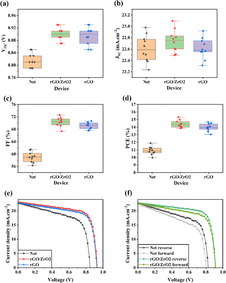
As explained in the experimental section, we synthesized the rGO/ZrO2 nanocomposite to use as a dopant for the mp-TiO2 precursor. Further discussion on the successful formation of this nanocomposite is provided in Notes 1 and 2, ESI.†As shown in Fig. 1, we fabricated perovskite solar cells with the normal structure of FTO/h-TiO2/mp-TiO2/FAPbI3/carbon. We doped the mp-TiO2 layer with the rGO/ZrO2 material to increase its potential as an ETL in HTL-free CPSCs. Indeed, different amounts of rGO/ZrO2 solution (5 mg mL−1 in EtOH) in varied volume ratios were added to the mp-TiO2 pre-solutions to obtain 0–6% rGO/ZrO2 doped ETL precursors. Employing different ETLs, we assembled HTL-free CPSCs and measured their J–V characteristics (Fig. S3†). Their calculated photovoltaic parameters are listed in Table S1.† As can be seen in Table S1,† by increasing the doping level of mp-TiO2 with rGO/ZrO2 up to 4%, the efficiency of the solar cells increased. When further increasing the dopant in the ETL, the photovoltaic efficiency of the devices was reduced. In the optimal doping level, a champion efficiency of 15.21% with a VOC of 0.930 V, JSC of 23.11 mA cm−2, and FF of 70.76% was recorded for HTL-free CPSCs. Meanwhile, a champion PCE of 11.88% with a VOC of 0.85 V, JSC of 22.79 mA cm−2, and FF of 61.32% was recorded for HTL-free CPSCs with net ETLs. Fig. S4† shows the IPCE spectra of the net and rGO/ZrO2-based HTL-free CPSCs to investigate the JSC calibration. The integrated JSC obtained for the net and rGO/ZrO2-based HTL-free CPSCs were 22.49 and 22.61 mA cm−2, respectively. The IPCE finding are in line with J–V measurements.
To show the novelty of the current study, we established a comparison between rGO and rGO/ZrO2. For this reason, we also doped mp-TiO2 ETLs with 4% rGO material, and based on these ETLs, we fabricated HTL-free CPSCs. For better insights, the statistical distributions of the VOC, JSC, FF, and PCE related to the net, rGO/ZrO2, and rGO-based devices are depicted in Fig. 2a–d. The corresponding photovoltaic parameters are listed in Table 1. Both the rGO- and rGO/ZrO2-doped devices recorded higher efficiencies. Notably, the rGO/ZrO2-doped devices displayed higher photovoltaic performances compared with the rGO-doped devices. In addition, Fig. 2e shows the J–V responses of the best-performing devices for these three kinds of ETLs. As listed in Table 1, the rGO-doped devices had a champion efficiency of 14.70%, lower than the recorded value for the rGO/ZrO2-doped devices. This comparison shows that rGO/ZrO2 is a better candidate than the pure rGO for ETL modification in PSCs.
| Device name | V OC (V) | J SC (mA cm−2) | FF (%) | PCE (%) | |
|---|---|---|---|---|---|
| Net | Average | 0.816 | 22.61 | 58.96 | 10.88 |
| Best | 0.850 | 22.79 | 61.32 | 11.88 | |
| rGO/ZrO2 | Average | 0.900 | 22.74 | 70.31 | 14.39 |
| Best | 0.930 | 23.11 | 70.76 | 15.21 | |
| rGO | Average | 0.894 | 22.62 | 69.09 | 13.97 |
| Best | 0.930 | 22.83 | 69.01 | 14.65 | |
Fig. 2e shows the J–V characteristics of HTL-free CPSCs based on net and rGO/ZrO2-doped ETLs in the reverse and forward sweep directions to study the effects of ETL modification on the hysteresis phenomenon. Calculating the PCE of devices in both directions and using the formula of  can obtain the HI value of the devices.32,33 The HI value of the net device was 11.22%, which was higher than the obtained HI value for the rGO/ZrO2-doped ETL (5.960%). As the literature reports, hysteresis in HTL-free CPSCs mainly relates to charge accumulation at perovskite interfaces with the ETL and carbon electrodes.34 Because rGO/ZrO2 affects the ETL/perovskite interface, it can be concluded that ETL modification reduces charge accumulation in the corresponding HTL-free CPSCs.
Fig. 3a shows the transmittance spectra of different mp-TiO2 ETLs. By adding 4% of rGO/ZrO2 or rGO to the mp-TiO2 layer, the transparency of ETL was slightly reduced. As shown in Fig. S5,† by increasing the doping level of rGO/ZrO2 to 6%, the transparency of the ETL was significantly reduced, which may be due to the reduced irradiance received by the perovskite layer and consequently the reduced current density in the solar cells. Fig. 3b shows the absorbance spectra of perovskite layers with net, 4% rGO/ZrO2-doped, and 4% rGO-doped ETLs. As can be seen, all the perovskite layers showed the same absorbance ability and the same absorbance edge position of 816 nm.35,36
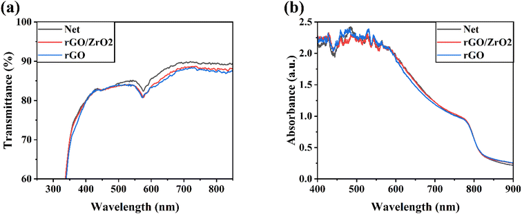 | ||
| Fig. 3 (a) Transmittance of different ETLs. (b) Absorbance of perovskites fabricated on different ETLs of net, rGO/ZrO2, and rGO. | ||
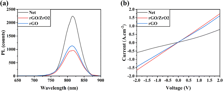
Fig. S6† shows the PL spectra of different perovskite layers fabricated on ETLs doped with 0–6% rGO/ZrO2 material. The results show that 4% rGO/ZrO2 increased the suppression of charge recombination in the perovskite layer, leading to efficiency improvements in the corresponding HTL-free CPSCs (see Table S1†). In addition, the PL spectra of perovskite layers with net, rGO/ZrO2, and rGO ETLs were measured (Fig. 4a). The incorporation of rGO or rGO/ZrO2 material to mp-TiO2 ETL suppressed the intensity of the PL peaks of the corresponding perovskites compared with net perovskite layer, indicating the reduced charge recombination in the ETLs-doped devices. Suppressing charge recombination in a solar cell increase its VOC parameter.37,38 Notably, the suppression of charge recombination in the rGO/ZrO2-doped ETL was higher than in the rGO-doped ETL, which concords with the results listed in Table 1. The reason behind the PL quenching in rGO/ZrO2 is the faster-transferring path for the photogenerated carriers from the FAPbI3 to the FTO, which decreases the recombination rates in the device.39 To prove this conclusion, the electrical conductivity of ETLs was measured by recording their dark I–V (Fig. 4b). As reported, the slope of the I–V curves is directly correlated with electrical conductivity, which means that a higher I–V slope indicates a higher conductivity. As depicted in Fig. 4b, the rGO/ZrO2-doped ETL had a higher electrical conductivity, even above that of the rGO-doped ETL, indicating a more facilitated charge transfer and improved FF parameter in this device.25,40
Fig. 5 shows the XRD pattern of FAPbI3 perovskite layers on the net, rGO/ZrO2-, and rGO-doped ETLs. All the perovskite layers showed the same α-phase crystal structure without any non-perovskite δ-phase, revealing the successful formation of perovskite layers using the anti-solvent assisted method.41,42 The ratios of the PbI2 phase to the (001) plane of FAPbI3 (Pb/(001)) were 0.381, 0.254, and 0.290 for the net, rGO/ZrO2-doped, and rGO-doped FAPbI3 layers, respectively. The reduced Pb/(001) in the doped ETLs compared with the net ETL indicated a partial suppression of the residual PbI2 in the perovskite layer, which weakened the reaction of unbonded PbI2 materials with humidity to accelerate perovskite degradation. As concluded by Gao et al.,43 too much lead iodide can jeopardize the performance of perovskite devices, while a moderate PbI2 excess is useful for the performance of PSCs. This dual nature of PbI2 excess has also been practically observed in research.44 In our case, we believe that the presence of 38% residual PbI2 can be considered too much PbI2 and needs to be reduced to lower levels. In addition, the intensified XRD peaks in the rGO/ZrO2-doped material suggest a better formation of FAPbI3 perovskite than the others, which can contribute to the improved photovoltaic performance of HTL-free CPSCs.
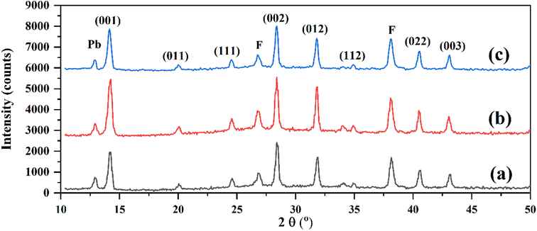 | ||
| Fig. 5 XRD patterns of different FAPbI3 layers. (a) Net ETL, (b) rGO/ZrO2-doped ETL, and (c) rGO-doped ETL. | ||
As shown in Fig. 6, the fabricated perovskite layer on the net ETL had obvious surface defects and pinholes (Fig. 6a). In contrast, the rGO/ZrO2- and rGO-doped ETLs were better substrates for perovskite formation, leading to lower defects and compact perovskite layers (Fig. 6b and c). The surface defects in the net perovskite layer act as charge traps and increase charge recombination in related HTL-free CPSCs, which reduces photovoltaic performance in solar cells. In addition, these defects increase the humidity adsorption in the perovskite surface, reducing the stability behavior of devices. To find a reason for the improved crystallinity and morphology of the FAPbI3 layer on the rGO/ZrO2-doped ETL, AFM tests were employed. The RMS roughness (Sq) of the net and rGO/ZrO2-doped ETL were obtained at 21.23 and 14.35 nm, indicating that the rGO/ZrO2 could reduce the surface roughness of mp-TiO2 layers. We believe a smoother ETL enables an easier spreading of the FAPbI3 precursor during the spin-coating process, which can guarantee the formation of the FAPbI3 phase during pouring the anti-solvent.
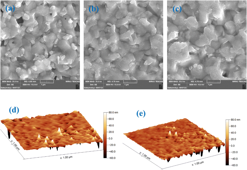 | ||
| Fig. 6 FESEM images of different perovskite layers fabricated on: (a) Net, (b) rGO/ZrO2-, and (c) rGO-doped ETLs. AFM images of (d) Net and (e) rGO/ZrO2-doped ETLs. | ||
To investigate the trap state density of the perovskite layers fabricated on different ETLs, electron-only devices were fabricated, and their dark J–V characteristics were recorded (Fig. 7a). As shown, the device with the rGO/ZrO2-doped ETL had a trap-filled limit voltage (VTFL) of 0.31 V, and the device with rGO-doped ETL had a higher VTFL of 0.41 V. The net ETL had the highest VTFL of 0.68 V. Having the value of VTFL, and using the following relation, the trap state density (Nt) can be calculated.45
 | (1) |
 | (2) |
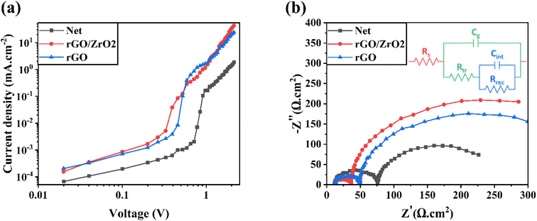 | ||
| Fig. 7 Electron only and EIS curves of (a) electron-only devices and (b) HTL-free CPSCs based on net, rGO/ZrO2, and rGO ETLs. | ||
The computed μ values for net, rGO/ZrO2-, and rGO-doped ETLs were 9.18 × 10⁻⁶, 3.09 × 10⁻³, and 1.45 × 10⁻³ cm2 V−1 s−1, respectively. The improved mobility was well consistent with the improved FF in the corresponding HTL-free CPSCs47–49 and supported the PL findings.
Deeper investigations into the charge transfer mechanism were carried out by measuring electrochemical impedance spectroscopy (EIS) of HTL-free CPSCs around the open-circuit voltage in dark conditions (Fig. 7b). By fitting Nyquist plots with equivalent circuit (inset of Fig. 7b), the transfer resistance (Rtr) and charge-recombination resistance (Rrec) could be found. As reported, the first semicircle is related to Rtr mainly at the perovskite interfaces. The second semicircle is related to Rrec at the bulk or perovskite interfaces. The Rtr values for the net, rGO/ZrO2-, and rGO-doped ETLs were obtained as 64.2, 24.7, and 37.2 Ω cm2, respectively. The reduced Rtr in the rGO/ZrO2-based devices indicated the faster charge recombination at the ETL/perovskite interface.50,51 The Rrec values for the net, rGO/ZrO2-, and rGO-doped ETLs were obtained as 184.6, 342.7, and 414.3 Ω cm2, respectively. The raised Rrec reveals the effectively reduced charge recombination.
Overall, as discussed in Note 1, ESI,† the incorporation of ZrO2 into the rGO sheets increased the electrical conductivity of the rGO materials. Therefore, doping the ETL with rGO/ZrO2 material increased the conductivity of the ETL, even higher than the net rGO dopant. The faster charge transfer at the ETL/perovskite interface caused by rGO/ZrO2 doping of the ETL reduced the charge accumulation at this interface and hindered charge recombination losses within the solar cells. These phenomena increase the photovoltaic performance of HTL-free CPSCs.
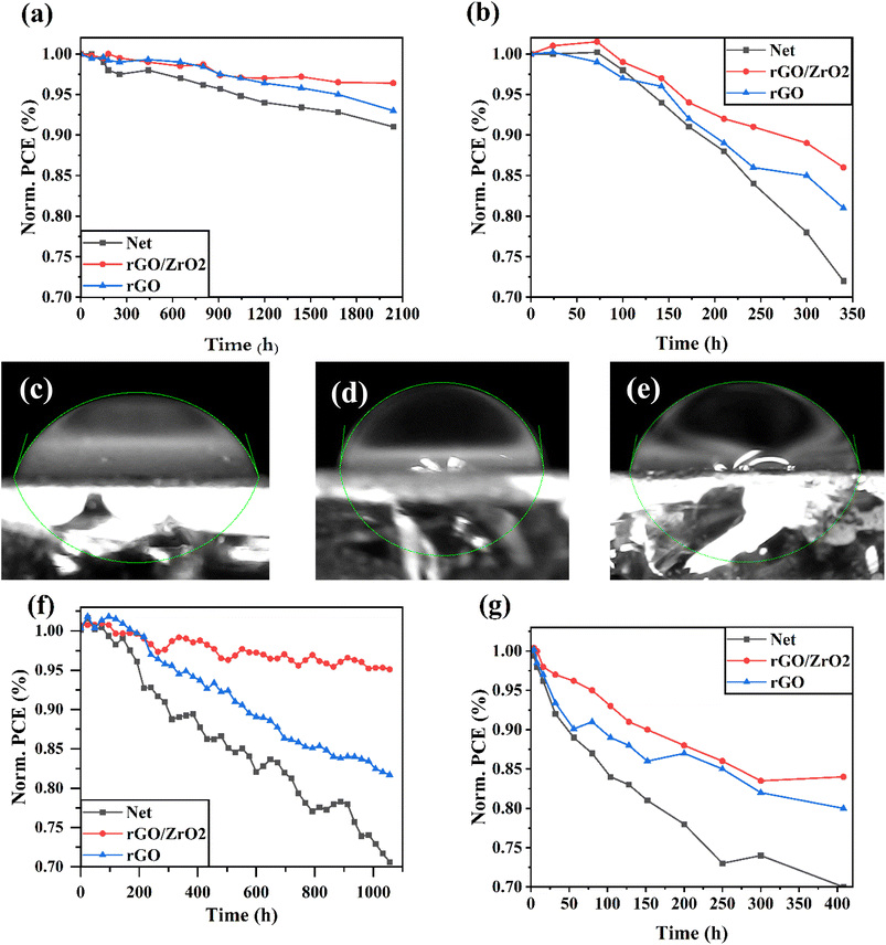
To monitor the stability of HTL-free CPSCs, different unencapsulated devices were kept in ambient air at room temperature (Fig. 8a) and in ambient air at a temperature of 50 °C (Fig. 8b), and their J–V responses were recorded during the aging time. As shown in Fig. 8, the rGO/ZrO2-based solar cells had more stable behavior than the net and rGO-based solar cells. The improved stability of the rGO/ZrO2-based devices was correlated to the boosted perovskite crystallinity and reduced surface defects.52 In addition, the contact angles of water droplets on the net, rGO/ZrO2, and rGO-based perovskite layers were measured (Fig. 8c–e). The contact angle of the water droplet on the rGO/ZrO2-based layer was 83.19°, higher than the 79.13° for rGO-based layer and 72.16° for the net layer. This indicated the rGO/ZrO2-based perovskite layer had more humidity resistance compared with the other layers, leading to its higher ambient air stability.49 For a deeper study on the improved thermal stability of rGO/ZrO2-based devices, XRD patterns of the net and rGO/ZrO2-based perovskite layers were investigated after 340 h aging time at ambient air at a temperature of 50 °C (Fig. S8†). It was found that the net perovskite layer during thermal stability degraded to organic components, leading to an intensified PbI2 phase in the layer, and also a weak non-perovskite FAPbI3 phase (δ-phase) was formed. In contrast, the degradation of the rGO/ZrO2-based perovskite layer during thermal stability was slight and was not observed in any δ-phase in its XRD pattern. Importantly, the light stability of unencapsulated HTL-free CPSCs was investigated under simulated sunlight irradiance in an inert N2 environment at a temperature of 30 °C (Fig. 8f). It was found that under irradiation, the rGO/ZrO2-based HTL-free CPSCs cell kept 95.1% of its pristine performance after 1056 h aging time, higher than the 70.6% remaining for the net HTL-free CPSCs. This was attributed to the improved crystalline properties of the rGO/ZrO2-based, which can avoid perovskite degradation under irradiance. Fig. 8g shows the thermal stability of HTL-free CPSCs at a temperature of 85 °C in an environment with a relative humidity of 25–30%. In the initial times of the stability test at the temperature of 85 °C, all the CPSC devices began to degrade faster than at the temperature of 50 °C, but eventually, the perovskites degradation rate decreased. It was found that the rGO/ZrO2-based HTL-free CPSCs cell kept 84%% of its initial PCE after 408 h aging time, higher than the 70% and 80% remaining for the net and rGO-based HTL-free CPSCs, respectively.
Conclusion
Herein, we developed rGO/ZrO2 nanocomposites to dope mp-TiO2 ETLs in HTL-free CPSCs. The results showed the rGO/ZrO2 dopant increased the electrical conductivity of the ETL, leading to reduced charge accumulation at the ETL/perovskite interface. In addition, it was observed that the rGO/ZrO2 dopant reduced the charge-transfer resistance in devices, suggesting a faster-transferring path for photogenerated carriers from the FAPbI3 to the FTO, which decreases the recombination rates in HTL-free CPSCs. Eventually, the modification of mp-TiO2 increased the efficiency of HTL-free CPSCs from 11.88% to 15.21%. Notably, our findings showed that the rGO/ZrO2 dopant compared with pure rGO is a better candidate for ETL modification. In addition, the rGO/ZrO2-based solar cells device showed improved stability against ambient air, heating and irradiance than the net HTL-free CPSCs.Data availability
Data will be available based on reasonable request.Conflicts of interest
There is no conflict of interest by any author.References
- H. S. Jung and N. G. Park, Perovskite solar cells: from materials to devices, Small, 2015, 11, 10–25 CrossRef CAS PubMed.
- M. Dehghanipour, A. Behjat and H. A. Bioki, Fabrication of stable and efficient 2D/3D perovskite solar cells through post-treatment with TBABF4, J. Mater. Chem. C, 2021, 9, 957–966 RSC.
- M. A. Green, A. Ho-Baillie and H. J. Snaith, The emergence of perovskite solar cells, Nat. Photonics, 2014, 8, 506–514 CrossRef CAS.
- M. Chen, P. Li, C. Liang, H. Gu, W. Tong, S. Cheng, W. Li, G. Zhao and G. Shao, Enhanced efficiency and stability of perovskite solar cells by 2D perovskite vapor-assisted interface optimization, J. Energy Chem., 2020, 45, 103–109 CrossRef.
- A. Abate, Y. Wu and M. Kuno, Energy Spotlight: New Advances in Metal Halide Perovskites, ACS Publications, 2023 Search PubMed.
- J. Hidalgo, L. Atourki, R. Li, A.-F. Castro-Méndez, S. Kim, E. A. Sherman, A. S. Bieber, M.-j. Sher, L. Nienhaus and C. A. Perini, Bulky cation hinders undesired secondary phases in FAPbI3 perovskite solar cells, Mater. Today, 2023, 68, 13–21 CrossRef CAS.
- Y. Cheng and L. Ding, Pushing commercialization of perovskite solar cells by improving their intrinsic stability, Energy Environ. Sci., 2021, 14, 3233–3255 RSC.
- P. Roy, N. K. Sinha, S. Tiwari and A. Khare, A review on perovskite solar cells: Evolution of architecture, fabrication techniques, commercialization issues and status, Sol. Energy, 2020, 198, 665–688 CrossRef CAS.
- R. Chen, Y. Feng, C. Zhang, M. Wang, L. Jing, C. Ma, J. Bian and Y. Shi, Carbon-based HTL-free modular perovskite solar cells with improved contact at perovskite/carbon interfaces, J. Mater. Chem. C, 2020, 8, 9262–9270 RSC.
- G. Grancini, C. Roldán-Carmona, I. Zimmermann, E. Mosconi, X. Lee, D. Martineau, S. Narbey, F. Oswald, F. De Angelis and M. Graetzel, One-Year stable perovskite solar cells by 2D/3D interface engineering, Nat. Commun., 2017, 8, 15684 CrossRef CAS PubMed.
- H. Zhang, Y. Li, S. Tan, Z. Chen, K. Song, S. Huang, J. Shi, Y. Luo, D. Li and Q. Meng, High-efficiency (> 20%) planar carbon-based perovskite solar cells through device configuration engineering, J. Colloid Interface Sci., 2022, 608, 3151–3158 CrossRef CAS PubMed.
- M. Que, B. Zhang, J. Chen, X. Yin and S. Yun, Carbon-based electrodes for perovskite solar cells, Mater. Adv., 2021, 2, 5560–5579 RSC.
- Z. Ku, Y. Rong, M. Xu, T. Liu and H. Han, Full printable processed mesoscopic CH3NH3PbI3/TiO2 heterojunction solar cells with carbon counter electrode, Sci. Rep., 2013, 3, 3132 CrossRef PubMed.
- Y. Rong, Z. Ku, A. Mei, T. Liu, M. Xu, S. Ko, X. Li and H. Han, Hole-conductor-free mesoscopic TiO2/CH3NH3PbI3 heterojunction solar cells based on anatase nanosheets and carbon counter electrodes, J. Phys. Chem. Lett., 2014, 5, 2160–2164 CrossRef CAS PubMed.
- Y. Wang, W. Li, Y. Yin, M. Wang, W. Cai, Y. Shi, J. Guo, W. Shang, C. Zhang and Q. Dong, Defective MWCNT Enabled Dual Interface Coupling for Carbon-Based Perovskite Solar Cells with Efficiency Exceeding 22, Adv. Funct. Mater., 2022, 32, 2204831 CrossRef CAS.
- Y. Xie, K. Zhao, H. Wang, Y. Qi, P. Wei and J. Cheng, Chitosan Derivatives Modified with SnO2 for High-Efficiency Carbon-Based Perovskite Solar Cells, ACS Appl. Energy Mater., 2023, 6, 7377–7386 CrossRef CAS.
- X. Zhang, Y. Guan, Y. Zhang, W. Yu, C. Wu, J. Han, Y. Zhang, C. Chen, S. Zheng and L. Xiao, Achieving Small Temperature Coefficients in Carbon-Based Perovskite Solar Cells by Enhancing Electron Extraction, Adv. Opt. Mater., 2022, 10, 2201598 CrossRef CAS.
- H. Liu, C. Geng, P. Wei, H. Chen, S. Zheng, H. Wang and Y. Xie, Improving the performance and stability of large-area carbon-based perovskite solar cells using N, O co-doped biomass porous carbon, J. Alloys Compd., 2022, 912, 165123 CrossRef CAS.
- Y. Qiang, Y. Xie, Y. Qi, P. Wei, H. Shi, C. Geng and H. Liu, Enhanced performance of carbon-based perovskite solar cells with a Li+-doped SnO2 electron transport layer and Al2O3 scaffold layer, Sol. Energy, 2020, 201, 523–529 CrossRef CAS.
- S. Li, Y. Li, X. Sun, Y. Li, F. Deng and X. Tao, Hole transport layer-free carbon-based perovskite solar cells with high-efficiency up to 17.49% in air: From-bottom-to-top perovskite interface modification, Chem. Eng. J., 2023, 455, 140727 CrossRef CAS.
- A. Kumar, M. Sayyed, S. Singh and M. K. Mohammed, Interface engineering of Tin (IV) oxide electron transport layer with Yttrium (III) fluoride for efficient carbon-based perovskite solar cells, Mater. Sci. Semicond. Process., 2023, 163, 107561 CrossRef CAS.
- Z. Wu, Y. Wang, L. Li, R. Zhang, J. Hong, R. Huang, L. Che, G. Yang, H. Rao and Z. Pan, Improving the Electron Transport Performance of TiO2 Film by Regulating TiCl4 Post-Treatment for High-Efficiency Carbon-Based Perovskite Solar Cells, Small, 2023, 2300690 CrossRef CAS PubMed.
- X. Liu, Z. Liu, B. Sun, X. Tan, H. Ye, Y. Tu, T. Shi, Z. Tang and G. Liao, All low-temperature processed carbon-based planar heterojunction perovskite solar cells employing Mg-doped rutile TiO2 as electron transport layer, Electrochim. Acta, 2018, 283, 1115–1124 CrossRef CAS.
- Q. He, H. Zhang, S. Han, R. Wang, Y. Li, X. Zhang and Y. Xing, Improvement of thiourea (Lewis base)-modified SnO2 electron-transport layer for carbon-based CsPbIBr2 perovskite solar cells, ACS Appl. Energy Mater., 2021, 4, 10958–10967 CrossRef CAS.
- H. Mohseni, M. Dehghanipour, N. Dehghan, F. Tamaddon, M. Ahmadi, M. Sabet and A. Behjat, Enhancement of the photovoltaic performance and the stability of perovskite solar cells via the modification of electron transport layers with reduced graphene oxide/polyaniline composite, Sol. Energy, 2021, 213, 59–66 CrossRef CAS.
- G. S. Han, Y. H. Song, Y. U. Jin, J.-W. Lee, N.-G. Park, B. K. Kang, J.-K. Lee, I. S. Cho, D. H. Yoon and H. S. Jung, Reduced graphene oxide/mesoporous TiO2 nanocomposite based perovskite solar cells, ACS Appl. Mater. Interfaces, 2015, 7, 23521–23526 CrossRef CAS PubMed.
- T. Umeyama, D. Matano, J. Baek, S. Gupta, S. Ito, V. Subramanian and H. Imahori, Boosting of the performance of perovskite solar cells through systematic introduction of reduced graphene oxide in TiO2 layers, Chem. Lett., 2015, 44, 1410–1412 CrossRef CAS.
- M. Khanzadeh, M. Dehghanipour, M. Karimipour and M. Molaei, Improvement of nonlinear optical properties of graphene oxide in mixed with Ag2S@ ZnS core-shells, Opt. Mater., 2017, 66, 664–670 CrossRef CAS.
- E. Nouri, M. R. Mohammadi, Z.-X. Xu, V. Dracopoulos and P. Lianos, Improvement of the photovoltaic parameters of perovskite solar cells using a reduced-graphene-oxide-modified titania layer and soluble copper phthalocyanine as a hole transporter, Phys. Chem. Chem. Phys., 2018, 20, 2388–2395 RSC.
- A. K. Kadhim, M. R. Mohammad, A. I. Abd Ali and M. K. Mohammed, Reduced graphene oxide/Bi2O3 composite as a desirable candidate to modify the electron transport layer of mesoscopic perovskite solar cells, Energy Fuels, 2021, 35, 8944–8952 CrossRef CAS.
- G. Bagha, H. Naffakh-Moosavy and M. R. Mersagh, The effect of reduced graphene oxide sheet on the optical and electrical characteristics of Ni-doped and Ag-doped ZnO ETLs in planar perovskite solar cells, J. Alloys Compd., 2021, 870, 159658 CrossRef CAS.
- M. K. Mohammed, A. E. Shalan, M. Dehghanipour and H. Mohseni, Improved mixed-dimensional 3D/2D perovskite layer with formamidinium bromide salt for highly efficient and stable perovskite solar cells, Chem. Eng. J., 2022, 428, 131185 CrossRef CAS.
- D.-Y. Son, S.-G. Kim, J.-Y. Seo, S.-H. Lee, H. Shin, D. Lee and N.-G. Park, Universal approach toward hysteresis-free perovskite solar cell via defect engineering, J. Am. Chem. Soc., 2018, 140, 1358–1364 CrossRef CAS PubMed.
- Q.-Q. Chu, Z. Sun, B. Ding, K.-s. Moon, G.-J. Yang and C.-P. Wong, Greatly enhanced power conversion efficiency of hole-transport-layer-free perovskite solar cell via coherent interfaces of perovskite and carbon layers, Nano Energy, 2020, 77, 105110 CrossRef CAS.
- A. Kumar, S. Singh, D. K. Sharma, M. Al-Bahrani, M. R. H. Alhakeem, A. Sharma and T. C. A. Kumar, Cetrimonium bromide and potassium thiocyanate assisted post-vapor treatment approach to enhance power conversion efficiency and stability of FAPbI3 perovskite solar cells, RSC Adv., 2023, 13, 1402–1411 RSC.
- X. Jiang, X. Wang, X. Wu, S. Zhang, B. Liu, D. Zhang, B. Li, P. Xiao, F. Xu and H. Lu, Strain Regulation via Pseudo Halide-Based Ionic Liquid toward Efficient and Stable α-FAPbI3 Inverted Perovskite Solar Cells, Adv. Energy Mater., 2023, 2300700 CrossRef CAS.
- N. Dehghan, A. Behjat, H. Zare, H. Mohseni and M. Dehghanipour, Modification of electron-transport layers with mixed RGO/C60 additive to boost the performance and stability of perovskite solar cells: A comparative study, Opt. Mater., 2021, 119, 111313 CrossRef CAS.
- H. Min, D. Y. Lee, J. Kim, G. Kim, K. S. Lee, J. Kim, M. J. Paik, Y. K. Kim, K. S. Kim and M. G. Kim, Perovskite solar cells with atomically coherent interlayers on SnO2 electrodes, Nature, 2021, 598, 444–450 CrossRef CAS PubMed.
- A. Khorasani, M. Marandi and N. Taghavinia, Electron transport engineering with different types of titanium dioxide nanostructures in perovskite solar cells, J. Alloys Compd., 2023, 936, 168055 CrossRef CAS.
- G. Nagaraj, M. K. Mohammed, M. Shekargoftar, P. Sasikumar, P. Sakthivel, G. Ravi, M. Dehghanipour, S. Akin and A. E. Shalan, High-performance perovskite solar cells using the graphene quantum dot-modified SnO2/ZnO photoelectrode, Mater. Today Energy, 2021, 22, 100853 CrossRef CAS.
- G. Murugadoss, P. Arunachalam, S. K. Panda, M. R. Kumar, J. R. Rajabathar, H. Al-Lohedan and M. Wasmiah, Crystal stabilization of α-FAPbI3 perovskite by rapid annealing method in industrial scale, J. Mater. Res. Technol., 2021, 12, 1924–1930 CrossRef CAS.
- Y. Zhou, M. Yang, J. Kwun, O. S. Game, Y. Zhao, S. Pang, N. P. Padture and K. Zhu, Intercalation crystallization of phase-pure α-HC (NH2)2PbI3 upon microstructurally engineered PbI2 thin films for planar perovskite solar cells, Nanoscale, 2016, 8, 6265–6270 RSC.
- Y. Gao, H. Raza, Z. Zhang, W. Chen and Z. Liu, Rethinking the Role of Excess/Residual Lead Iodide in Perovskite Solar Cells, Adv. Funct. Mater., 2023, 2215171 CrossRef CAS.
- T. J. Jacobsson, J.-P. Correa-Baena, E. Halvani Anaraki, B. Philippe, S. D. Stranks, M. E. Bouduban, W. Tress, K. Schenk, J. Teuscher and J.-E. Moser, Unreacted PbI2 as a double-edged sword for enhancing the performance of perovskite solar cells, J. Am. Chem. Soc., 2016, 138, 10331–10343 CrossRef CAS PubMed.
- M. Dehghanipour, A. Behjat, A. Shabani and M. Haddad, Toward desirable 2D/3D hybrid perovskite films for solar cell application with additive engineering approach, J. Mater. Sci.: Mater. Electron., 2022, 33, 12953–12964 CrossRef CAS.
- C. Jiang, J. Zhou, H. Li, L. Tan, M. Li, W. Tress, L. Ding, M. Grätzel and C. Yi, Double layer composite electrode strategy for efficient perovskite solar cells with excellent reverse-bias stability, Nano-Micro Lett., 2023, 15, 12 CrossRef CAS PubMed.
- S. H. Kareem, M. H. Elewi, A. M. Naji, D. S. Ahmed and M. K. Mohammed, Efficient and stable pure α-phase FAPbI3 perovskite solar cells with a dual engineering strategy: additive and dimensional engineering approaches, Chem. Eng. J., 2022, 443, 136469 CrossRef.
- X. Tang, S. Xiao, Q. Fu, Y. Chen and T. Hu, Incorporation of two electron acceptors to improve the electron mobility and stability of perovskite solar cells, J. Mater. Chem. C, 2019, 7, 8344–8349 RSC.
- X. Li, X. Wu, B. Li, Z. Cen, Y. Shang, W. Lian, R. Cao, L. Jia, Z. Li and D. Gao, Modulating the deep-level defects and charge extraction for efficient perovskite solar cells with high fill factor over 86, Energy Environ. Sci., 2022, 15, 4813–4822 RSC.
- D. Yang, R. Yang, J. Zhang, Z. Yang, S. F. Liu and C. Li, High efficiency flexible perovskite solar cells using superior low temperature TiO2, Energy Environ. Sci., 2015, 8, 3208–3214 RSC.
- M. K. Mohammed, M. Dehghanipour, U. Younis, A. E. Shalan, P. Sakthivel, G. Ravi, P. H. Bhoite and J. Pospisil, Improvement of the interfacial contact between zinc oxide and a mixed cation perovskite using carbon nanotubes for ambient-air-processed perovskite solar cells, New J. Chem., 2020, 44, 19802–19811 RSC.
- D. A. Noori, A. Behjat and M. Dehghanipour, Operational stability study of hole transport-free perovskite solar cells using lithium fluoride in electron transport layer, J. Mater. Sci.: Mater. Electron., 2023, 34, 592 CrossRef CAS.
Footnote |
| † Electronic supplementary information (ESI) available. See DOI: https://doi.org/10.1039/d3na00757j |
| This journal is © The Royal Society of Chemistry 2024 |

