
 Open Access Article
 This Open Access Article is licensed under a Creative Commons Attribution-Non Commercial 3.0 Unported Licence
Intrafibrillar mineralization of type I collagen with calcium carbonate and strontium carbonate induced by polyelectrolyte–cation complexes†
Yizhou
Zhang‡
a,
Yiru
Wang‡
a,
Zhengyi
Zhang
a,
Zhe
Wang
a,
Changyu
Shao
 a,
Matthias
Hannig
b,
Zihuai
Zhou
*a and
Baiping
Fu
*a
a,
Matthias
Hannig
b,
Zihuai
Zhou
*a and
Baiping
Fu
*a
aStomatology Hospital, School of Stomatology, Zhejiang University School of Medicine, Zhejiang Provincial Clinical Research Center for Oral Diseases, Key Laboratory of Oral Biomedical Research of Zhejiang Province, Cancer Center of Zhejiang University, Engineering Research Center of Oral Biomaterials and Devices of Zhejiang Province, Hangzhou 310000. E-mail: fbp@zju.edu.cn; 11818406@zju.edu.cn
bClinic of Operative Dentistry, Periodontology and Preventive Dentistry, Saarland University, 66421 Homburg, Germany
First published on 29th November 2023
Abstract
Calcium carbonate (CaCO3), possessing excellent biocompatibility, bioactivity, osteoconductivity and superior biodegradability, may serve as an alternative to hydroxyapatite (HAp), the natural inorganic component of bone and dentin. Intrafibrillar mineralization of collagen with CaCO3 was achieved through the polymer-induced liquid precursor (PILP) process for at least 2 days. This study aims to propose a novel pathway for rapid intrafibrillar mineralization with CaCO3 by sequential application of the carbonate–bicarbonate buffer and polyaspartic acid (pAsp)-Ca suspension. Fourier transform infrared (FTIR) spectroscopy, zeta potential measurements, atomic force microscopy/Kelvin probe force microscopy (AFM/KPFM), and three-dimensional stochastic optical reconstruction microscopy (3D STORM) demonstrated that the carbonate–bicarbonate buffer significantly decreased the surface potential of collagen and CO32−/HCO3− ions could attach to collagen fibrils via hydrogen bonds. The electropositive pAsp–Ca complexes and free Ca2+ ions are attracted to and interact with CO32−/HCO3− ions through electrostatic attractions to form amorphous calcium carbonate that crystallizes gradually. Moreover, like CaCO3, strontium carbonate (SrCO3) can deposit inside the collagen fibrils through this pathway. The CaCO3-mineralized collagen gels exhibited better biocompatibility and cell proliferation ability than SrCO3. This study provides a feasible strategy for rapid collagen mineralization with CaCO3 and SrCO3, as well as elucidating the tissue engineering of CaCO3-based biomineralized materials.
1 Introduction
Biominerals are formed in living organisms through self-regulation by incorporating natural elements into hierarchically structured organic–inorganic skeletons.1 Biomineralization is a unique example of natural self-assembly and has arisen broad interests of scientists for decades.2,3 The organic matrix typically serves as a template for biomineralization under the control of non-collagenous proteins (NCPs).4 However, the inorganic minerals provide great mechanical and biological properties for the organic matrix.5–7Carbonate minerals exist widely in the natural environment.8 Among them, calcium carbonate (CaCO3) is one of the most prevalent biominerals.9 Aragonite, the metastable phase of CaCO3, is the main inorganic phase of coral skeletons and nacre.10,11 The skeletal parts of sea urchins, sea stars, and brittle stars are composed of calcite, the most stable phase of CaCO3.12 Herein, scientists have developed a large number of bio-inspired materials with CaCO3 minerals making up the primary inorganic phase.4
Type I collagen is recognized as the most abundant fibrillar protein in the extracellular matrix and serves as a template for mineralization in hard tissues, including bone and dentin.3,5 Hierarchical mineralization especially intrafibrillar mineralization endows the hard tissue with excellent mechanical and biological properties.5–7 Hydroxyapatite (HAp) is the primary inorganic component of bone and dentin.13 Replacement of intrafibrillar HAp crystallites with CaCO3 might provide excellent biocompatibility, bioactivity, high osteoconductivity and superior biodegradability for the mineralized matrix.3,14,15
Intrafibrillar mineralization with CaCO3 was previously achieved through the polymer-induced liquid precursor (PILP) process in various reconstituted collagen matrixes and demineralized natural dentin.4,16–18 Intrafibrillar collagen mineralization with CaCO3 was induced by amorphous calcium carbonate (ACC) precursors in the PILP process via capillary action or electrostatic attraction.16,19,20 Nevertheless, despite the stability of polyelectrolytes, the supersaturated mineralizing media lost their efficacy due to the crystallization of the metastable precursors in solution.21 Moreover, the efficiency of the PILP process was significantly low, and mineralization was completed in at least two days.18,22,23 Therefore, the clinical application and industrial production via the PILP process require further research and improvement.
NCPs play a crucial regulatory role in biomineralization due to their remarkable electronegativity. Anionic polyelectrolytes are widely used as NCP analogues.4,19 The negatively charged polystyrene sulfonate (PSS) could capture numerous Ca2+ ions to form PSS–Ca complexes, attracting CO32− ions to produce ACC for mineralization.24 The PSS–Ca complexes immobilized onto Si3N4 substrates could interact with CO32− ions through carbon dioxide (CO2) gas diffusion, creating a local supersaturation that facilitates ACC formation.25
Following the discovery of polyelectrolyte–Ca complexes, we proposed the polyelectrolyte–calcium complex pre-precursor (PCCP) process for rapid collagen mineralization with HAp.26 Mineralization was induced by using a highly concentrated polyaspartic acid (pAsp)-Ca suspension followed by a phosphate solution. However, intrafibrillar mineralization with CaCO3 was not achieved using the pAsp-Ca suspension followed by the carbonate–bicarbonate buffer.
In contrast, intrafibrillar mineralization occurred when the application sequence was reversed in this study. The collagen fibrils were incubated in the carbonate–bicarbonate buffer for 3 h. CO32−/HCO3− ions could infiltrate and bind to collagen via hydrogen bonds, significantly decreasing the surface potential of the collagen fibrils. After the treatment with the pAsp-Ca suspension for 30 min, the electropositive pAsp-Ca complexes and excess free Ca2+ ions were rapidly attracted to and interacted with CO32−/HCO3− ions through electrostatic attraction. ACC formed inside the collagen and crystallized gradually (Fig. 1). The CaCO3-mineralized collagen gels were biocompatible and promoted cell proliferation. Strontium is an indispensable element for the human body, resembling calcium in size and properties.27,28 Herein, the calcium was replaced with strontium, and the intrafibrillar collagen mineralization with SrCO3 was accomplished. This study provides a feasible strategy for intrafibrillar mineralization with CaCO3 and SrCO3 instead of the PILP and PCCP processes. It may highlight the potential biomedical applications of CaCO3-based biomineralized materials.
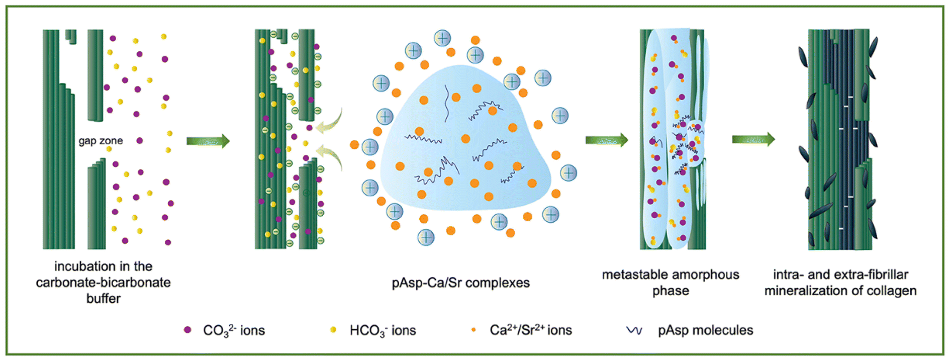 | ||
| Fig. 1 Schematic diagram of the mineralization process proposed in this study. The CO32−/HCO3− ions infiltrated and bound to collagen fibrils, followed by the recruitment of pAsp-Ca/Sr complexes and Ca2+/Sr2+ ions. Intrafibrillar metastable amorphous mineral precursors were generated and eventually transformed into crystallites. | ||
2 Experimental
2.1. Materials and methods
The materials used in this study were commercially purchased. They included NaHCO3, KCl, dimethyl sulphoxide (DMSO) and (3-aminopropyl) triethoxysilane (APTES) (Macklin Biochemical Co., China); hexamethyl disilylamine (HMDS), SrCl2·6H2O, calcein sodium salt (Mw: 666.5 Da), 25 wt% of glutaraldehyde solution and phosphate buffered saline (PBS, 0.01 M, pH = 7.2–7.4) (Aladdin, China); poly-L-asparate acid (pAsp, Mw: 6–8 kDa, Aike Reagent, China); NaOH and Na2CO3 (Sinopharm Chemical Reagent Co., China); CaCl2·2H2O, 5-fluorescein isothiocyanate, glycine, catalase, cysteamine and glucose oxidase (Sigma-Aldrich, USA); uranyl acetate (SPI-CHEM, USA); calcein/PI cell viability/cytotoxicity assay kit, blocking buffer and washing buffer (10×) (Beyotime, China); 300-mesh nickel TEM grids (Beijing XXBR Technology Co., China); Q-Sense gold-SiO2 QCM wafer (Shenzhen Renlux Crystal Co., China); CCK-8 cell proliferation and cytotoxicity assay kit, penicillin-streptomycin liquid (100×), 0.25% of trypsin–EDTA solution and PBS (0.1 M, pH = 7.2–7.4) (Beijing Solarbio Science & Technology Co., China); fetal bovine serum (FBS, Biological Industries, Israel); bovine tendon type I collagen stock solution (Chengdu Kele Biological Technology Co., China); goat anti rabbit Alexafluor 647 antibody (ab150083) and rabbit anti-collagen I antibody (ab34710) (Abcam, UK); Dulbecco's modified eagle medium (DMEM, Hyclone, USA); type I collagen stock solution (rat tail, 3 mg mL−1, Gibco-Invitrogen, USA).2.2. Preparation and characterization of the mineralizing media
![[thin space (1/6-em)]](https://www.rsc.org/images/entities/char_2009.gif) :3 and the pH value was exactly about 9.5 ± 0.2. The total concentration of CO32− and HCO3− ions was approximately 1.65 M, resulting in a buffer concentration of 1.65 M. The pAsp-Ca suspension (4 g L−1–5.44 M) was prepared by mixing 10 mL of 10 g L−1 pAsp solution and 20 g of CaCl2·2H2O and adjusting the pH to 9.5 ± 0.2 with 10 M NaOH. The final concentrations of pAsp and calcium were approximately 4 g L−1 and 5.44 M, respectively. Similarly, the pAsp-Sr suspension (2 g L−1 and 2.75 M) was prepared by dissolving 11 g of SrCl2·6H2O in 10 mL of 3 g L−1 pAsp solution and adjusting the pH to 9.5 ± 0.2 with 1 M NaOH. The final concentrations of pAsp and strontium were approximately 2 g L−1 and 2.75 M, respectively.
:3 and the pH value was exactly about 9.5 ± 0.2. The total concentration of CO32− and HCO3− ions was approximately 1.65 M, resulting in a buffer concentration of 1.65 M. The pAsp-Ca suspension (4 g L−1–5.44 M) was prepared by mixing 10 mL of 10 g L−1 pAsp solution and 20 g of CaCl2·2H2O and adjusting the pH to 9.5 ± 0.2 with 10 M NaOH. The final concentrations of pAsp and calcium were approximately 4 g L−1 and 5.44 M, respectively. Similarly, the pAsp-Sr suspension (2 g L−1 and 2.75 M) was prepared by dissolving 11 g of SrCl2·6H2O in 10 mL of 3 g L−1 pAsp solution and adjusting the pH to 9.5 ± 0.2 with 1 M NaOH. The final concentrations of pAsp and strontium were approximately 2 g L−1 and 2.75 M, respectively.
2.3. Mineralization of the reconstituted single-layer type I collagen fibrils
2.4. Mineralization of the reconstituted type I collagen gels
2.5. Biocompatibility testing
2.6. The interaction of CO32−/HCO3− ions with collagen fibrils
3 Results and discussion
3.1. Characterization of the pAsp-Ca/Sr suspensions
The pAsp-Ca/Sr suspension contained pAsp-Ca/Sr complexes and free Ca2+/Sr2+ ions (Fig. 2).26 Due to the limited solubility of SrCl2, the concentration of the pAsp-Sr suspension was approximately half that of the pAsp-Ca suspension. One Ca2+ ion could bind to two carboxyl groups (–COOH) of one or two pAsp molecules.26 Hence, the concentration of carboxyl groups from pAsp molecules in the pAsp-Ca suspension was calculated to be approximately 17.5 mM, which could capture 17.5–35.0 mM Ca2+ ions.33 Similarly, approximately 8.75–17.5 mM Sr2+ ions could bind to pAsp molecules as the concentration of pAsp in the pAsp-Sr suspension was half that of the pAsp-Ca suspension. Due to the ultra-high Ca2+/Sr2+ ion concentrations, numerous Ca2+/Sr2+ ions were in the free ionic state in the suspension. The STEM images show that pAsp-Ca/Sr complexes were in irregular shapes (Fig. 2a and d). It could be ascribed to the random coil shapes of pAsp molecules.34 The element mapping results reveal the distribution of calcium/strontium, carbon, oxygen, and nitrogen in the pAsp-Ca/Sr complexes (Fig. 2a and d). The HRTEM images with SAED patterns show the amorphous phase of these complexes (Fig. S1†). The average particle sizes of the pAsp-Ca and pAsp-Sr complexes were about 261.72 ± 12.42 nm and 298.69 ± 10.67 nm, respectively (Fig. 2b, c and e, f). Due to the abundance of Ca2+/Sr2+ ions over the carboxyl groups, the zeta potentials of the pAsp-Ca and pAsp-Sr suspensions were 6.62 ± 0.18 and 6.99 ± 0.19 mV, respectively. Moreover, the osmolarities of the 10-time diluted pAsp-Ca and pAsp-Sr suspensions were 1303.67 ± 3.30 mOsm kg−1 and 669.33 ± 1.25 mOsm kg−1, respectively, while those of the 10-time diluted pAsp solution were 2.00 ± 0.00 mOsm kg−1 and 1.00 ± 0.00 mOsm kg−1, respectively. Therefore, the numerous Ca2+/Sr2+ ions dominated the osmolarities, and pAsp molecules contributed minimally to the osmolarities of the pAsp-Ca/Sr suspensions.26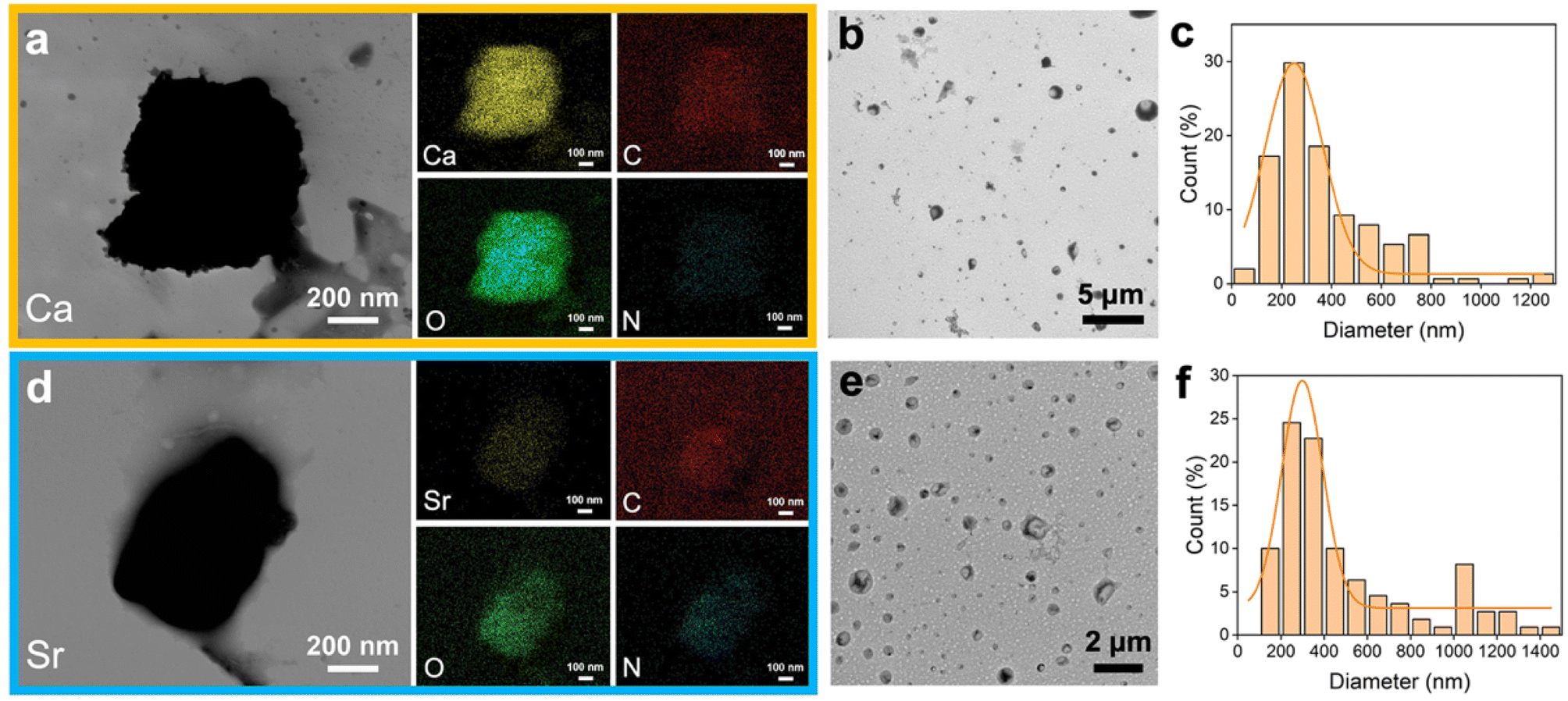 | ||
| Fig. 2 Characterization of the pAsp-Ca/Sr complexes. (a) STEM image with elemental mapping results of an isolated pAsp-Ca complex. (b) TEM image of the pAsp-Ca complexes in the pAsp-Ca suspension. (c) The size distribution of the pAsp-Ca complexes in “b” reveals an average size of 261.72 ± 12.42 nm. (d) STEM image with elemental mapping results of an isolated pAsp-Sr complex. (e) TEM image of the pAsp-Sr complexes in the pAsp-Sr suspension. (f) The size distribution of the pAsp-Sr complexes in “e” reveals an average size of 298.69 ± 10.67 nm. Ca/Sr: yellow, C: red, O: green, N: blue. | ||
3.2. Intrafibrillar mineralization of reconstituted single-layer type I collagen fibrils
Reconstituted type I collagen stained with uranyl acetate exhibited typical periodic 67 nm patterns, indicating the successful self-assembly of collagen fibrils (Fig. S2†).13 After the collagen fibrils were incubated in the carbonate–bicarbonate buffer for 3 h, no pronounced increase in the electron density of collagen fibrils was detected (Fig. 3a). The collagen fibrils were then treated with the pAsp-Ca suspension for 30 min, and both heavy intra- and extra-fibrillar mineralization were achieved (Fig. 3b and c). The HRTEM image (Fig. 3d) with SAED pattern (Fig. 3e) reveals that the intrafibrillar minerals were a mixture of vaterite and aragonite. The minor arc-shaped diffraction patterns suggest small lattice distortions between the boundaries of intrafibrillar crystallites (Fig. 3e). Aragonite (PDF 33-0268) is represented by (111), (002), and (041) planes, whereas the vaterite (PDF 41-1475) is represented by the (008) plane. The HRTEM image shows that the interplanar spacing of 3.40 Å is ascribed to the characteristic (111) crystal planes of aragonite (PDF 33-0268) (Fig. 3f). The STEM-EDX images exhibit the distribution of calcium, carbon, oxygen and nitrogen, indicating the deposition of CaCO3 crystallites inside collagen fibrils (Fig. 3g).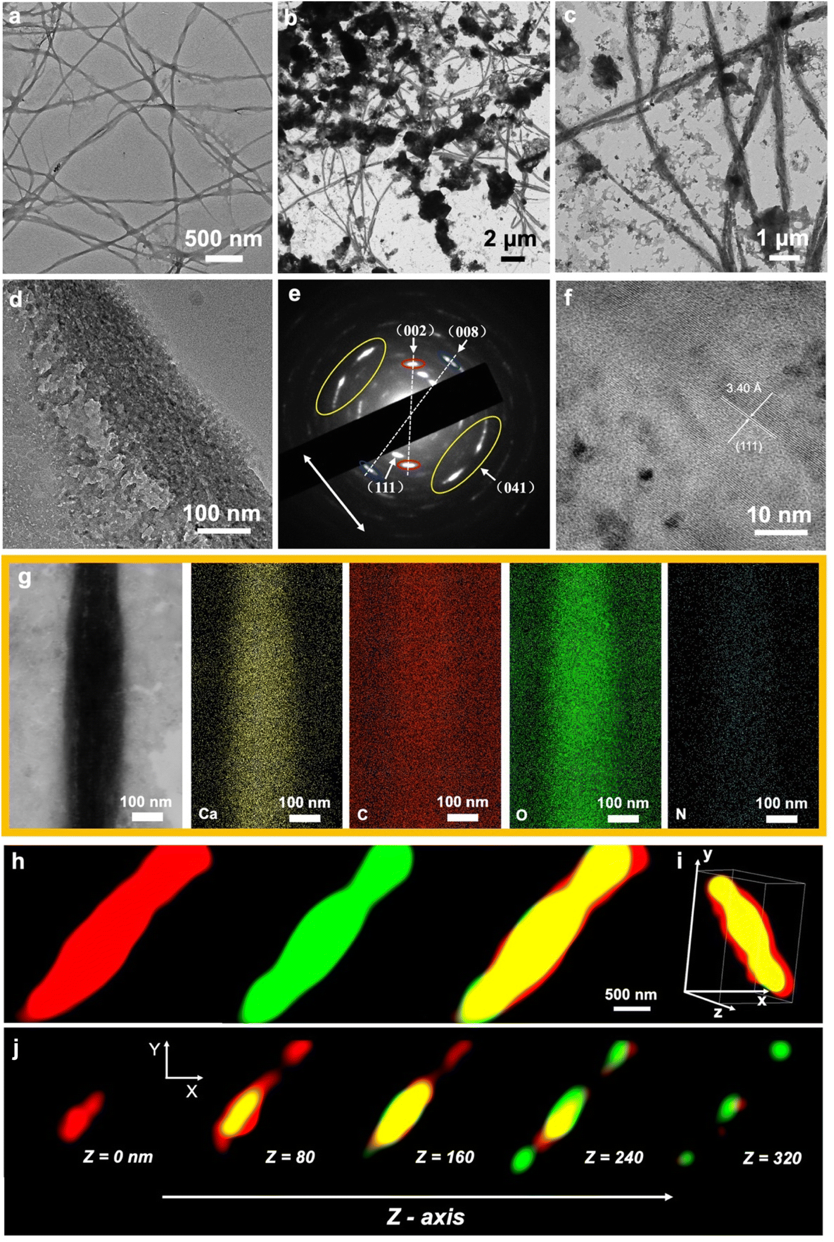 | ||
| Fig. 3 Intrafibrillar mineralization of single-layer collagen fibrils with CaCO3. (a) TEM image of the collagen fibrils incubated in the carbonate–bicarbonate buffer for 3 h. (b) TEM image of the mineralized collagen fibrils after the sequential incubation in the carbonate–bicarbonate buffer for 3 h and pAsp-Ca suspension for 30 min. (c) Magnification of “b”. (d) HRTEM image of the mineralized collagen fibril. (e) SAED pattern of the collagen fibril in “d”. The arcs of aragonite (002) diffraction, aragonite (041) diffraction and vaterite (008) diffraction are highlighted in red, yellow and blue circles, respectively. The long axis of the collagen fibril in “d” is highlighted with white arrows. (f) Magnification of the HRTEM image in “d”. (g) STEM image with elemental mapping results of an isolated mineralized collagen fibril (Ca: yellow, C: red, O: green, N: blue). (h) The STORM images of a mineralized collagen fibril. The immunofluorescently labeled collagen fibril emitted red fluorescence. Calcein-labeled CaCO3 emitted green fluorescence. Red fluorescence and green fluorescence were merged in yellow. (i) 3D visualization of the spatial distribution of intrafibrillar CaCO3 crystallites. (j) The z-slices of the STORM images in “h” with an interval of 80 nm. | ||
Notably, the SAED pattern shows the multi-axial orientation of intrafibrillar CaCO3 crystallites. The c-axis of intrafibrillar vaterite crystallites was nearly perpendicular to the collagen long axis, while the intrafibrillar aragonite crystallites were oriented with the (041) crystal plane along the fibril (Fig. 3e). Vaterite and aragonite phases have anisotropic crystal structures, however, they prefer to grow along their c-axis.23,35 This may indicate that ACC initially filled gap zones, transformed into vaterite crystallites and deposited inside the gap zones. Intrafibrillar vaterite crystallites grew along their c-axis approximately perpendicular to the collagen long axis due to the confinement within gap zone channels.23 The residual ACC occupied the overlap zones and transformed into aragonite phase.23 However, the intrafibrillar aragonite crystallites were oriented with the (041) crystal plane along the fibril rather than their c-axis. It could be due to the polycrystalline structures inside the fibrils. The differences in crystal morphologies between vaterite and aragonite and the confinement induced by the collagen may change the fastest-growing direction and distort the structure of aragonite crystallites.
The intrafibrillar mineralization with CaCO3 was further verified via the STORM technique. The immunofluorescently labelled collagen fibrils emitted red fluorescence and calcein-labelled CaCO3 crystallites emitted green fluorescence (Fig. 3g). The overlapping yellow regions in 3D visualization (Fig. 3h) and continuous z-slicing of the reconstructed 3D-STORM model (Fig. 3i) represent the intrafibrillar CaCO3 crystallites.
To validate the efficacy of the proposed pathway, the pAsp-Sr suspension was applied in the same way (Fig. 4). The TEM images exhibit heavy intra- and extra-fibrillar mineralization of collagen fibrils after the incubation in the carbonate–bicarbonate buffer for 3 h followed by the pAsp-Sr suspension for 1 h (Fig. 4a and b). The HRTEM image with the SAED pattern reveals typical (111), (002), (012), (200), (221) and (132) planes of the intrafibrillar SrCO3 crystallites (PDF 05-0418) (Fig. 4c). Furthermore, the typical diffraction arc (002) indicates that intrafibrillar SrCO3 crystallites grew along their c-axis, parallel to the long axis of the fibril. The HRTEM image shows that the interplanar spacings of 2.55 Å and 3.00 Å correspond to the characteristic (200) and (002) crystal planes of SrCO3, respectively (PDF 05-0418) (Fig. 4d). The STEM image of the mineralized collagen fibril exhibits a high electron density, and elemental mapping images show the distributions of strontium, carbon, oxygen and nitrogen, indicating the deposition of SrCO3 crystallites within fibrils (Fig. 4e).
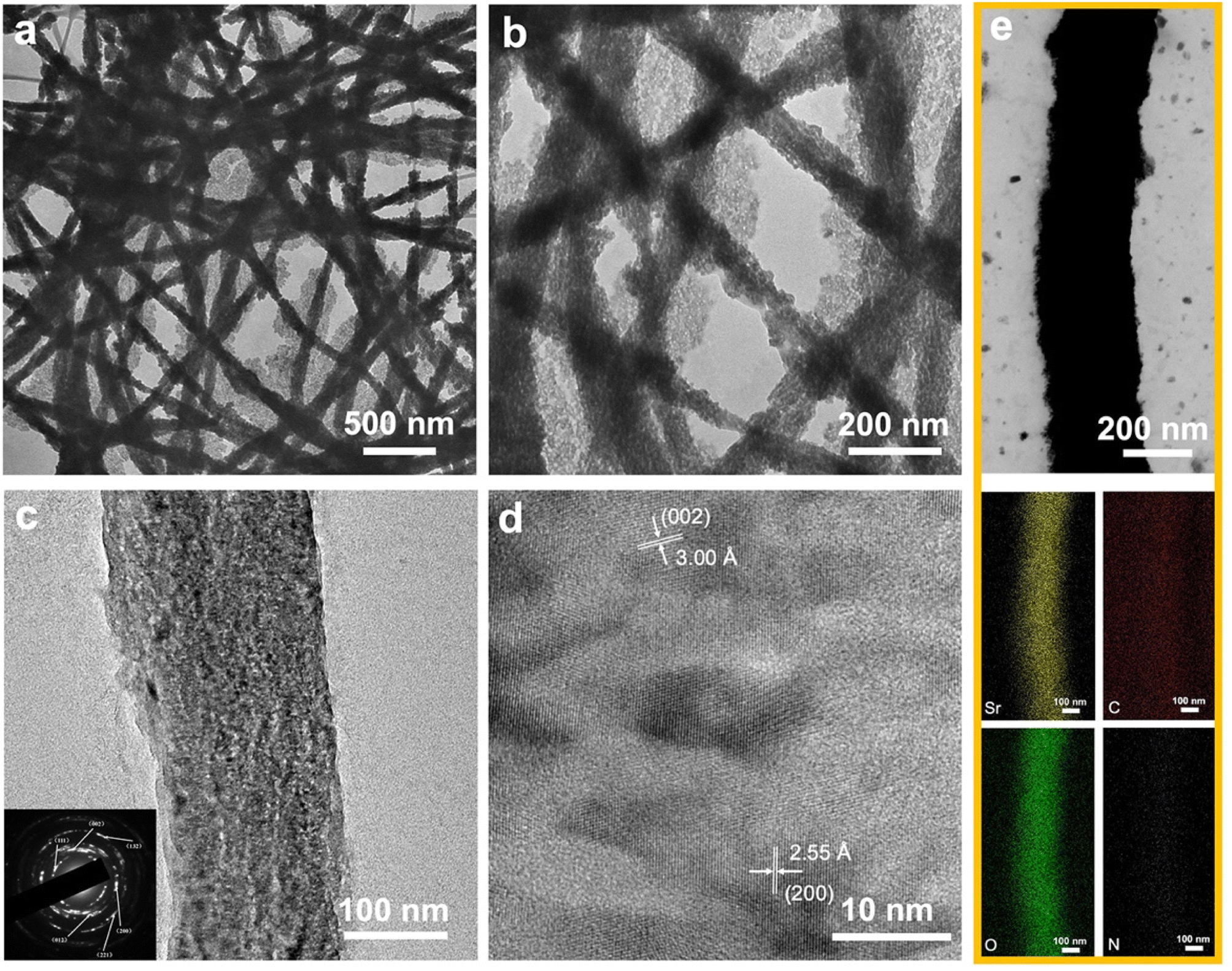 | ||
| Fig. 4 Intrafibrillar mineralization of single-layer collagen fibrils with SrCO3. (a) TEM image of the mineralized collagen fibrils after sequential incubation in the carbonate–bicarbonate buffer for 3 h and pAsp-Sr suspension for 1 h. (b) Magnification of “a”. (c) HRTEM image with the SAED pattern of a mineralized collagen fibril. (d) Magnification of the HRTEM image in “c”. (e) STEM image with elemental mapping results of a mineralized collagen fibril (Sr: yellow, C: red, O: green, N: blue). | ||
3.3. Mineralization of the reconstituted type I collagen gels (CGs)
The reconstituted single-layer collagen model is two-dimensional (2D), whereas the natural collagen matrix in hard tissues is three-dimensional (3D) and difficult to mineralize.36 Therefore, the reconstituted type I collagen gel was used as a 3D collagen model to validate the proposed process. The pure collagen gel exhibited a smooth surface with a typical D-band pattern (Fig. 5a and b). The collagen fibrils of the mineralized gels were embedded in the minerals, and the structure was unclear (Fig. 5c–f). The Ca-CG contained massive crystals resembling the typical rhombohedral calcite structure (Fig. 5c and d) in the interfibrillar spaces.37 The loosely formed interfibrillar spherical crystals could be observed in the Sr-CG (Fig. 5e and f). | ||
| Fig. 5 Characterization of the CGs, Ca-CGs and Sr-CGs. (a–f) FESEM images of the unmineralized/mineralized reconstituted collagen gels. (a and b) Low- (a) and high- (b) magnification images of the CG reveal a smooth surface of the pure collagen fibrils. (c and d) Low- (c) and high (d) magnification images of the Ca-CG show a rough surface of the collagen fibrils. (e and f) Low- (e) and high- (f) magnification images of the Sr-CG indicate heavy mineralization. (g) ATR-FTIR spectra show the typical absorption peaks of CO32− ions in Ca-CG and Sr-CG in comparison with CG. (h and i) XRD spectra of the Ca-CG (h) and Sr-CG (i) confirm the existence of CaCO3 and SrCO3 crystallites inside the collagen gels, respectively. (j and k) TGA results of CGs, Ca-CGs and Sr-CGs. The calculated mineral/collagen weight ratios (j) and mineral weight percentages (k) show that the mineral contents of Ca-CGs and Sr-CGs were significantly higher than those of CGs (n = 3, ***P < 0.001). (l) The Ca2+/Sr2+ ion release curves of Ca-CGs and Sr-CGs show a sustained release of Ca2+ ions during 28 days and a burst release of Sr2+ ions during the first 5 days. | ||
The ATR-FTIR spectra and XRD patterns were used to identify the minerals within the collagen gels. The ATR-FTIR spectrum of the CG shows the characteristic peaks of amide I (C![[double bond, length as m-dash]](https://www.rsc.org/images/entities/char_e001.gif) O stretch), amide II (N–H in-plane bend), amide III (C–N stretch and the N–H in-plane bend) and amide A (N–H stretch) bands at 1630 cm−1, 1552 cm−1, 1241 cm−1 and 3293 cm−1, respectively (Fig. 5g).38 The characteristic peaks of 1391 cm−1, 1082 cm−1, 871 cm−1 and 711 cm−1 of the Ca-CG are assigned to the ν3, ν1, ν2 and ν4 absorption bands of CO32− ions, respectively. The CO32−ν2 and ν4 bands indicate the presence of vaterite and calcite, respectively.18,39 The presence of calcite is consistent with the rhombohedral particles in the interfibrillar space (Fig. 5c and d).4 As for the Sr-CG, the characteristic peak at 1771 cm−1 corresponds to the O–H vibration, while the peaks at 1436 cm−1, 1071 cm−1, 856 cm−1 and 705 cm−1 correspond to the ν3, ν1, ν2 and ν4 vibrations bands of CO32− ions, respectively (Fig. 5g).40 The XRD patterns are consistent with the ATR-FTIR spectra. The XRD pattern of the Ca-CG reveals that the diffraction peaks correspond to the (012), (104), (006), (110), (113), (202), (018), (116), (211), (122), (214) and (300) crystal planes of the calcite phase (PDF 47-1743) and the (110), (112), (114), (300) and (118) crystal planes of the vaterite phase (PDF 33-0268) (Fig. 5h). Compared with the SAED result (Fig. 3e) of the single-layer collagen model, no aragonite was detected in the collagen gels. The intrafibrillar aragonite might transform into the calcite phase in the collagen gel model. The XRD pattern of the Sr-CG shows distinct diffraction peaks, including (110), (111), (021), (002), (012), (200), (112), (130), (220), (221), (041), (132), (113), (114) and (313) crystal planes of the SrCO3 phase (PDF 05-0418) (Fig. 5i), corroborating the deposition of SrCO3 crystallites in the Sr-CG.
O stretch), amide II (N–H in-plane bend), amide III (C–N stretch and the N–H in-plane bend) and amide A (N–H stretch) bands at 1630 cm−1, 1552 cm−1, 1241 cm−1 and 3293 cm−1, respectively (Fig. 5g).38 The characteristic peaks of 1391 cm−1, 1082 cm−1, 871 cm−1 and 711 cm−1 of the Ca-CG are assigned to the ν3, ν1, ν2 and ν4 absorption bands of CO32− ions, respectively. The CO32−ν2 and ν4 bands indicate the presence of vaterite and calcite, respectively.18,39 The presence of calcite is consistent with the rhombohedral particles in the interfibrillar space (Fig. 5c and d).4 As for the Sr-CG, the characteristic peak at 1771 cm−1 corresponds to the O–H vibration, while the peaks at 1436 cm−1, 1071 cm−1, 856 cm−1 and 705 cm−1 correspond to the ν3, ν1, ν2 and ν4 vibrations bands of CO32− ions, respectively (Fig. 5g).40 The XRD patterns are consistent with the ATR-FTIR spectra. The XRD pattern of the Ca-CG reveals that the diffraction peaks correspond to the (012), (104), (006), (110), (113), (202), (018), (116), (211), (122), (214) and (300) crystal planes of the calcite phase (PDF 47-1743) and the (110), (112), (114), (300) and (118) crystal planes of the vaterite phase (PDF 33-0268) (Fig. 5h). Compared with the SAED result (Fig. 3e) of the single-layer collagen model, no aragonite was detected in the collagen gels. The intrafibrillar aragonite might transform into the calcite phase in the collagen gel model. The XRD pattern of the Sr-CG shows distinct diffraction peaks, including (110), (111), (021), (002), (012), (200), (112), (130), (220), (221), (041), (132), (113), (114) and (313) crystal planes of the SrCO3 phase (PDF 05-0418) (Fig. 5i), corroborating the deposition of SrCO3 crystallites in the Sr-CG.
The weight ratio of mineral/collagen and the weight percentage of minerals inside the gels were estimated based on the TGA results. The weight loss below 200 °C was ascribed to the evaporation of water. The weight loss between 200 and 600 °C was assigned to the decomposition of collagen.29 The residual weight represented inorganic minerals, because the decomposition temperatures of CaCO3 and SrCO3 crystallites are both higher than 600 °C.41–45 As a consequence, the mineral/collagen weight ratios of Ca-CGs and Sr-CGs were 2.40 ± 0.137 and 3.67 ± 0.065, respectively, evidently higher than CGs (0.327 ± 0.034, P < 0.001) (Fig. 5j). The weight percentages of Ca-CGs and Sr-CGs were 70.58 ± 1.18% and 78.57 ± 0.30%, respectively, markedly higher than 24.58 ± 1.98% of CGs (P < 0.001) (Fig. 5k). The mineral content of the mineralized collagen gels was comparable to that of natural bone, which contains 65 wt% mineral phase.13,46 The calculated atomic contents of calcium and strontium per gram of pure collagen gel were 24.21 ± 1.39 mM and 24.84 ± 0.44 mM, respectively. Therefore, the concentrations of CaCO3 and SrCO3 per unit mass of the pure collagen gel were similar (P > 0.05).
ICP-OES measurements determined the ion release of Ca-CGs and Sr-CGs. The ion release curve indicates a sustained release of Ca2+/Sr2+ ions during 28 days. The concentration of Ca2+ ions was 16.87 ± 4.00 ppm on day 1, gradually decreasing to 4.32 ± 1.40 ppm on day 14, thus maintaining stability. However, the Sr2+ ion release curve exhibits a burst release of Sr2+ ions in the initial stage, increasing from 70.73 ± 4.42 ppm on day 1 to 81.82 ± 0.36 ppm on day 5. Afterwards, the release of Sr2+ ions dropped sharply to a plateau of 63.43 ± 3.74 ppm on day 14 (Fig. 5l). The concentration of Sr2+ ions released substantially surpassed that of Ca2+ ions at each time point (P < 0.001), despite the equality in CaCO3 and SrCO3 concentrations per unit mass within the pure collagen gel (Fig. 5k). Moreover, CaCO3 presents a higher solubility compared to SrCO3.47,48 It might imply a higher degree of intrafibrillar mineralization of Ca-CGs than Sr-CGs, as the collagen could be a predictable barrier to prevent the outflow of functional cations, and the intrafibrillarly mineralized collagen gels are predisposed to release cations sustainably.49 Moreover, the higher crystallinity of intrafibrillar minerals inside Ca-CGs versus Sr-CGs might result in better retention of intrafibrillar CaCO3 crystallites.
3.4. Evaluation of the biocompatibility of mineralized collagen gels
The collagen gel model could be used to mimic the physiological extracellular organic matrix for evaluation of the biocompatibility of mineralized collagen materials.50 Numerous studies indicate that calcium and strontium promote bone formation in adequate concentrations,51–53 therefore, we attempted to incorporate Ca2+/Sr2+ ions into the reconstituted collagen gels via biomimetic mineralization. Hence, the biocompatibility of Ca-CGs and Sr-CGs as potential biomedical materials was assessed by CCK-8 assay and live/dead staining assay. According to the results of CCK-8 assay, CGs, Ca-CGs and Sr-CGs exhibited comparable levels of cell proliferation after 1 day of co-cultivation with rBMSCs. The cell proliferation on Ca-CGs was remarkably higher than CGs on days 3 and 7, and higher than Sr-CGs on days 3, 5 and 7, suggesting their superior biocompatibility and noncytotoxicity. However, the cell proliferation on Sr-CGs showed insignificant differences compared to CGs during the first 3 days and even a lower level on days 5 and 7, suggesting cell cytotoxicity of Sr-CGs (Fig. 6a). The live/dead staining assay also revealed comparable results (Fig. 6b). No significant dead cells (red staining) were found in CGs and Ca-CGs during the 7-day cultivation. The cells in both groups demonstrated satisfactory cell proliferation, indicating the biocompatibility of CGs and Ca-CGs. Furthermore, the cells on Ca-CGs proliferated faster than cells on CGs and Sr-CGs at each time point, implying that CaCO3 could stimulate cell proliferation. However, compared to CGs, more dead cells were found in Sr-CGs after 3-day cultivation and the cell proliferation rate was apparently slower on days 5 and 7, implying cell cytotoxicity of Sr-CGs. The results abovementioned were consistent with the release curve of Sr2+ ions, which showed a burst release in the first 5 days and the concentration of Sr2+ ions was significantly higher than Ca2+ ions all the time (P < 0.001) (Fig. 5l), because a high dose of Sr2+ ions could induce cell cytotoxicity on rBMSCs.54 Similar results have been reported for pure strontium HAp (without calcium in the HAp) as a high concentration of the released Sr2+ ions caused cytotoxicity and limited its application in hard tissue regeneration.30 | ||
| Fig. 6 Biocompatibility of mineralized collagen gels against rBMSCs. (a) CCK-8 assay results of CGs, Ca-CGs and Sr-CGs co-cultivated with rBMSCs for 1, 3, 5 and 7 days (n = 3, *P < 0.05, **P < 0.01). (b) Fluorescence microscopic images of rBMSCs co-cultured with CGs, Ca-CGs and Sr-CGs for 1, 3, 5 and 7 days using calcein-AM/PI staining. Live and dead cells were stained in green and red, respectively. | ||
Overall, Ca-CGs are more compatible with rBMSCs than Sr-CGs. However, their potential to promote osteogenesis and the associated pathway still requires further research. Intrafibrillar mineralization with Sr-doped CaCO3 could potentially yield osteopromotive effects as the strontium element has been amply documented for its capacity to stimulate osteogenesis.27 We have recently attempted (Fig. S3–S5†) and achieved (Fig. S5†) intrafibrillar mineralization with Sr-doped CaCO3 using reconstituted single-layer collagen models. Further research is required to explore its application potential in biomedical fields.
3.5. Differences between the proposed process and the PILP and PCCP processes
Calcium phosphate (CaP) is the main inorganic component of natural bone and dentin.3 CaCO3 might be an alternative to HAp due to its high bioactivity, biocompatibility, high osteoconductivity and superior biodegradability compared to HAp.3,14,15 CaCO3-based collagen materials with intrafibrillar CaCO3 crystallites deposition could be recognized as a blueprint for hard tissue regeneration.14,55,56 Until now, intrafibrillar mineralization with either CaP or CaCO3 has been achieved via the PILP process.16,19,57 The PILP process is based on liquid-like amorphous mineral precursors with plasticity and high hydration that infiltrate collagen fibrils through gap zones.20,58 NCPs or their analogs could initially inhibit nucleation and stabilize the formed ACC phase.4 The ACC penetrated into the collagen fibrils probably through capillary action or electrostatic attraction.16,19,20 The clinical and industrial applications of the PILP process are restricted by the limited mineralization efficiency at such low concentrations and the instability of ACC precursors.To overcome these limitations, the polyelectrolyte–calcium complex pre-precursor (PCCP) process was proposed to induce rapid intrafibrillar mineralization for reconstituted collagen fibrils and demineralized dentin matrix by sequentially applying ultra-highly concentrated pAsp-Ca suspension and phosphate solution.26,59 Amorphous calcium phosphate (ACP) was generated inside the collagen fibrils and gradually transformed into HAp in artificial saliva. Moreover, intrafibrillar mineralization could not be achieved when the sequences of the pAsp-Ca suspension and phosphate solution order were switched.26 The electronegative phosphate groups were excluded from the collagen fibrils due to the electrostatic repulsion. Extrafibrillar apatite deposition was observed even after the fibrils were treated with the pAsp-Ca suspension. Similar procedures were used for intrafibrillar mineralization with CaCO3 to discover a new pathway for manufacturing CaCO3-based biomineralized materials. However, the anticipated intrafibrillar mineralization could not be achieved when the fibrils were sequentially treated with the pAsp-Ca suspension and carbonate–bicarbonate buffer (Fig. S6†). ACC was initially generated within collagen fibrils, while intrafibrillar minerals gradually decreased in the carbonate–bicarbonate buffer (Fig. S6†). This phenomenon could be explained by the experiment demonstrating that ACC could be intrinsically stabilized by HCO3− ions in a physiological environment.60 Herein, intrafibrillar ACC was stabilized by numerous HCO3− ions in the carbonate–bicarbonate buffer and gradually diffused outwards. Intrafibrillar mineralization occurred when the collagen fibrils were treated with the carbonate–bicarbonate buffer before pAsp-Ca suspension (Fig. 3).
To better understand the mechanism of the proposed strategy in this study, the interaction between CO32−/HCO3− ions and collagen fibrils was further explored via FTIR spectra, CD spectra and AFM/KPFM analyses. The FTIR spectrum of the carbonate–bicarbonate buffer-treated collagen gel (C-CG) shows a decreased intensity of the characteristic peaks of collagen (1652 cm−1, 1554 cm−1, 1239 cm−1 and 3318 cm−1) compared to CGs. The new peaks at 866 cm−1, 1083 cm−1 and 1453 cm−1 represent the ν2, ν1 and ν3 vibrational modes of the CO32−/HCO3− ions, respectively. The peak at 1033 cm−1 is assigned to the C–OH group of HCO3− ions.61 The peak of amide A (N–H stretching vibration) slightly redshifts from 3328 cm−1 to 3318 cm−1 due to the hydrogen bond between CO32−/HCO3− ions and collagen, stabilizing the triple-helical structure of collagen (Fig. 7a).62,63
 | ||
| Fig. 7 The influence of CO32−/HCO3− ions on the structure of collagen fibrils. (a) FTIR spectra of the CG and C-CG. (b) CD spectra of the pure collagen and carbonate–bicarbonate buffer-treated collagen. (c–h) AFM/KPFM images and surface potentials of pure collagen (c–e) and carbonate–bicarbonate buffer treated-collagen (f–h). The topography (c) and VCPD distribution (d) of the pure collagen fibril were measured to calculate the surface potential distribution (Vsample = Vtip − VCPD) along the collagen fibril, revealing an average surface potential of −0.83 ± 1.50 mV (e). The topography (f) and VCPD distribution (g) of the carbonate–bicarbonate buffer-treated collagen fibril were analyzed to calculate the average surface potential as −29.07 ± 5.69 mV (h). | ||
Additionally, CD spectra analysis was used to analyze the changes in the secondary structure of collagen.64 In the CD spectra, a minimum negative absorption peak at 197 nm, and a crossover point at 214 nm along with a maximal positive absorption peak at 222 nm reveal the triple helical conformation characteristics of both pure collagen and the carbonate–bicarbonate buffer-treated collagen.65 The parameter Rpn, the ratio of the absolute peak intensities at 222 nm and 197 nm, is a criterion for evaluating the triple helical conformation of collagen.66 In our experiment, the Rpn values of pure collagen and the carbonate–bicarbonate buffer-treated collagen were measured to be 0.1180 and 0.1311, respectively (Fig. 7b), indicating a higher stability of the collagen triple helix after the incubation in the carbonate–bicarbonate buffer.63 This result was consistent with the FTIR spectra of the hydrogen bond formed between collagen fibrils and CO32−/HCO3− ions (Fig. 7a).
AFM/KPFM was used to identify changes in the surface potential of the collagen fibrils after the incubation in the carbonate–bicarbonate buffer (Fig. 7c–h). The AFM image shows the typical periodic banding structure of the pure assembled collagen (Fig. 7c). The surface potentials along the collagen fibril exhibited interlaced positive and negative peaks with an average surface potential value of −0.83 ± 1.50 mV (Fig. 7d and e). No apparent topographical changes were observed in the collagen fibrils after a 3-hour incubation in the carbonate–bicarbonate buffer (Fig. 7f). The treated collagen fibrils were negatively charged with an average surface potential value decreasing to −29.07 ± 5.69 mV (P < 0.001) (Fig. 7g and h).
The spatial distribution of pAsp molecules was also investigated via the 3D-STORM technique. The pAsp molecules were found to be inside the carbonate–bicarbonate treated fibrils after the incubation in pAsp-Ca suspension for 30 min (Fig. S7†). In corroboration with the findings indicating that Ca2+ ions were also inside the fibrils (Fig. 3h–j), it could be concluded that pAsp-Ca complexes infiltrated the carbonate–bicarbonate treated-collagen fibrils after 30 min-incubation in the pAsp-Ca suspension.
4 Conclusion
In contrast to the PILP and PCCP processes, the CO32−/HCO3− ions could interact with and attach to the collagen fibrils via hydrogen bonds, improving the stability of the collagen triple-helix structure and increasing the electronegativity of collagen fibrils, that facilitate the infiltration of pAsp-Ca/Sr complexes and Ca2+/Sr2+ ions through electrostatic attraction. Subsequently, ACC/ASC formed and crystallized gradually within collagen, inducing intrafibrillar mineralization with CaCO3/SrCO3. The acquired Ca-CGs had better biocompatibility than Sr-CGs, highlighting the potential biomedical applications of CaCO3-based biomineralized materials. The potential of Ca-CGs to promote osteogenesis and biodegradability in vivo will be investigated further.Author contributions
Yizhou Zhang designed the research and carried out the experiments, analysed the data and wrote the manuscript. Yiru Wang carried out the biocompatibility testing and AFM/KPFM. Zhengyi Zhang conducted CD spectra analysis and prepared figures. Zhe Wang and Changyu Shao suggested the research design. Matthias Hannig and Zihuai Zhou suggested the research design and assisted in revising the manuscript. Baiping Fu supervised the project and revised the manuscript. All authors reviewed and discussed the manuscript.Conflicts of interest
The authors (B. Fu, Y. Zhang, Z. Zhou and Y. Wang) declared that they have applied for patents concerning the collagen scaffolds mineralized with carbonates and their application in China (no. ZL202310494884.X). The other authors declare no conflict of interest.Acknowledgements
Y. Zhang and Y. Wang contributed equally to this work. This research was supported by the National Natural Science Foundation of China [grant numbers 81970982 and 82201120] and Zhejiang Key Research and Development Plan [grant number 2020C03037]. The authors thank Nianhang Rong, Xi Zheng, Li Xie, Xiaomin Zhang, Jin Niu, Xiaohuan Zhao and Huanmin Qian in the Analysis Center of Agrobiology and Environmental Sciences, Faculty of Agriculture, Life and Environment Sciences, Zhejiang University (ZJU) for their assistance in the TEM and SEM observation. The authors thank Dandan Song in the Center of Cryo-Electron Microscopy, Zhejiang University (ZJU), China, for assistance in STEM-EDS analysis. The authors also thank Jing He in the State Key Laboratory of Chemical Engineering, ZJU, China, for the technical assistance in AFM/KPFM. The authors thank Wei Yin in the Core Facilities, Zhejiang University School of Medicine, China, for assistance in 3D-STORM.References
- K. Grandfield, C. Micheletti, J. Deering, G. Arcuri, T. Tang and B. Langelier, Acta Biomater., 2022, 148, 44–60 CrossRef CAS PubMed.
- C. Y. Wang, K. Jiao, J. F. Yan, M. C. Wan, Q. Q. Wan, L. Breschi, J. H. Chen, F. R. Tay and L. N. Niu, Prog. Mater. Sci., 2021, 116, 100712 CrossRef CAS.
- B. M. Oosterlaken, M. P. Vena and G. de With, Adv. Mater., 2021, 33, e2004418 CrossRef PubMed.
- H. Ping, H. Xie, Y. M. Wan, Z. X. Zhang, J. Zhang, M. Y. Xiang, J. J. Xie, H. Wang, W. M. Wang and Z. Y. Fu, J. Mater. Chem. B, 2016, 4, 880–886 RSC.
- W. J. Landis, F. H. Silver and J. W. Freeman, J. Mater. Chem., 2006, 16, 1495–1503 RSC.
- Y. Liu, N. Li, Y. P. Qi, L. Dai, T. E. Bryan, J. Mao, D. H. Pashley and F. R. Tay, Adv. Mater., 2011, 23, 975–980 CrossRef CAS PubMed.
- J. Li, J. F. Yan, Q. Q. Wan, M. J. Shen, Y. X. Ma, J. T. Gu, P. Gao, X. Y. Tang, F. Yu, J. H. Chen, F. R. Tay, K. Jiao and L. N. Niu, Acta Biomater., 2021, 125, 112–125 CrossRef CAS PubMed.
- Z. Z. Han, D. Li, H. Zhao, H. X. Yan and P. Y. Li, Minerals, 2017, 7, 95 CrossRef.
- F. C. Meldrum, Int. Mater. Rev., 2003, 48, 187–224 CrossRef CAS.
- M. C. Wan, W. Qin, C. Lei, Q. H. Li, M. Meng, M. Fang, W. Song, J. H. Chen, F. R. Tay and L. N. Niu, Bioact. Mater., 2021, 6, 4255–4285 CAS.
- E. M. Gerhard, W. Wang, C. Y. Li, J. S. Guo, I. T. Ozbolat, K. M. Rahn, A. D. Armstrong, J. F. Xia, G. Y. Qian and J. Yang, Acta Biomater., 2017, 54, 21–34 CrossRef CAS PubMed.
- Y. Politi, T. Arad, E. Klein, S. Weiner and L. Addadi, Science, 2004, 306, 1161–1164 CrossRef CAS PubMed.
- M. J. Olszta, X. G. Cheng, S. S. Jee, R. Kumar, Y. Y. Kim, M. J. Kaufman, E. P. Douglas and L. B. Gower, Mater. Sci. Eng., R, 2007, 58, 77–116 CrossRef.
- A. D. Woldetsadik, S. K. Sharma, S. Khapli, R. Jagannathan and M. Magzoub, ACS Biomater. Sci. Eng., 2017, 3, 2457–2469 CrossRef CAS PubMed.
- W. Yang, C. X. Yao, Z. Y. Cui, D. D. Luo, I. S. Lee, J. M. Yao, C. Chen and X. D. Kong, Int. J. Mol. Sci., 2016, 17, 639 CrossRef PubMed.
- M. J. Olszta, E. P. Douglas and L. B. Gower, Calcif. Tissue Int., 2003, 72, 583–591 CrossRef CAS PubMed.
- D. C. Bassett, B. Marelli, S. N. Nazhat and J. E. Barralet, Adv. Funct. Mater., 2012, 22, 3460–3469 CrossRef CAS.
- M. Wang, H. B. Deng, T. Jiang and Y. N. Wang, Biomater. Adv., 2022, 135, 112670 CrossRef PubMed.
- L. Yu and M. Wei, Int. J. Mol. Sci., 2021, 22, 944 CrossRef CAS PubMed.
- F. Nudelman, K. Pieterse, A. George, P. H. Bomans, H. Friedrich, L. Brylka, P. J. Hilbers, G. de With and N. J. M. Sommerdijk, Nat. Mater., 2010, 9, 1004–1009 CrossRef CAS PubMed.
- T. Iwatsubo, K. Sumaru, T. Kanamori, T. Yamaguchi and T. Sinbo, J. Appl. Polym. Sci., 2004, 91, 3627–3634 CrossRef CAS.
- Y. Wang, N. Van Manh, H. R. Wang, X. Zhong, X. Zhang and C. Y. Li, Int. J. Nanomed., 2016, 11, 2053–2067 CAS.
- Y. F. Xu, F. Nudelman, E. D. Eren, M. M. Wirix, B. Cantaert, W. H. Nijhuis, D. Hermida-Merino, G. Portale, P. H. Bomans, C. Ottmann, H. Friedrich, W. Bras, A. Akiva, J. R. O. Orgel, F. Meldrum and N. Sommerdijk, Nat. Commun., 2020, 11, 5068 CrossRef CAS PubMed.
- T. X. Wang, H. Cölfen and M. Antonietti, J. Am. Chem. Soc., 2005, 127, 3246–3247 CrossRef CAS PubMed.
- P. M. Smeets, K. R. Cho, R. E. Kempen, N. J. M. Sommerdijk and J. De Yoreo, Nat. Mater., 2015, 14, 394–399 CrossRef CAS PubMed.
- Z. H. Zhou, L. Q. Zhang, J. C. Li, Y. Shi, Z. F. Wu, H. Y. Zheng, Z. Wang, W. J. Zhao, H. H. Pan, Q. Wang, X. G. Jin, X. Zhang, R. K. Tang and B. P. Fu, Nanoscale, 2021, 13, 953–967 RSC.
- W. H. Wang and K. K. Yeung, Bioact. Mater., 2017, 2, 224–247 Search PubMed.
- C. G. Huang, J. L. Zhou, J. Rao, X. Y. Zhao, X. M. Tian, F. P. He and H. S. Shi, Colloids Surf., B, 2022, 218, 112755 CrossRef CAS PubMed.
- C. Y. Shao, R. B. Zhao, S. Q. Jiang, S. S. Yao, Z. F. Wu, B. Jin, Y. L. Yang, H. H. Pan and R. K. Tang, Adv. Mater., 2018, 30, 1704876 CrossRef PubMed.
- Z. Ye, Y. P. Qi, A. Q. Zhang, B. J. Karels and C. Aparicio, ACS Macro Lett., 2023, 12, 408–414 CrossRef CAS PubMed.
- J. Elango, J. Y. Zhang, B. Bao, K. Palaniyandi, S. J. Wang, W. H. Wu and J. S. Robinson, Int. J. Biol. Macromol., 2016, 91, 51–59 CrossRef CAS PubMed.
- J. Lü, E. Delamarche, L. Eng, R. Bennewitz, E. Meyer and H. J. Güntherodt, Langmuir, 1999, 15, 8184–8188 CrossRef.
- M. B. Gindele, K. K. Malaszuk, C. Peter and D. Gebauer, Langmuir, 2022, 38, 14409–14421 CrossRef CAS PubMed.
- A. Tsortos and G. H. Nancollas, J. Colloid Interface Sci., 2002, 250, 159–167 CrossRef CAS PubMed.
- M. G. Willinger, J. Polleux, M. Antonietti, H. Cölfen, N. Pinna and N. Nassif, CrystEngComm, 2015, 17, 3927–3935 RSC.
- W. J. Jin, Y. L. Jin, P. Q. Duan, H. Y. Wu, L. Q. Zhang, Q. L. Du, H. H. Pan, R. K. Tang and C. Y. Shao, J. Mater. Chem. B, 2022, 10, 5826–5834 RSC.
- Z. Y. Zou, L. Bertinetti, Y. Politi, P. Fratzl and W. E. M. Habraken, Small, 2017, 13, 1603100 CrossRef PubMed.
- T. Riaz, R. Zeeshan, F. Zarif, K. Ilyas, N. Muhammad, S. Z. Safi, A. Rahim, S. A. A. Rizvi and I. U. Rehman, Appl. Spectrosc. Rev., 2018, 53, 703–746 CrossRef CAS.
- D. M. Sun and Q. S. Wu, Chin. J. Chem., 2004, 22, 1067–1069 CrossRef CAS.
- K. M. Sajesh, K. Kiran, S. V. Nair and R. Jayakumar, Composites, Part B, 2016, 99, 445–452 CrossRef CAS.
- K. S. P. Karunadasa, C. H. Manoratne, H. M. T. G. A. Pitawala and R. M. G. Rajapakse, J. Phys. Chem. Solids, 2019, 134, 21–28 CrossRef CAS.
- T. Tone and N. Koga, ACS Omega, 2021, 6, 13904–13914 CrossRef CAS PubMed.
- P. Ptáček, E. Bartoníčková, J. Švec, T. Opravil, F. Šoukal and F. Frajkorová, Ceram. Int., 2015, 41, 115–126 CrossRef.
- S. W. Lee, Y. J. Kim, Y. H. Lee, H. Guim and S. M. Han, Mater. Des., 2016, 112, 367–373 CrossRef CAS.
- N. B. Singh and N. P. Singh, J. Therm. Anal. Calorim., 2007, 89, 159–162 CrossRef CAS.
- H. Ping, W. Wagermaier, N. Horbelt, E. Scoppola, C. H. Li, P. Werner, Z. Y. Fu and P. Fratzl, Science, 2022, 376, 188–192 CrossRef CAS PubMed.
- K. Sawada, Pure Appl. Chem., 1997, 69, 921–928 CrossRef CAS.
- R. W. Clark and J. M. Bonicamp, J. Chem. Educ., 1998, 75, 1182–1185 CrossRef CAS.
- H. H. Liu, M. L. Lin, X. Liu, Y. Zhang, Y. Y. Luo, Y. Y. Pang, H. T. Chen, D. W. Zhu, X. Zhong, S. Q. Ma, Y. H. Zhao, Q. Yang and X. Zhang, Bioact. Mater., 2020, 5, 844–858 Search PubMed.
- C. A. R. Jones, M. Cibula, J. C. Feng, E. A. Krnacik, D. H. Mclntyre, H. Levine and B. Sun, Proc. Natl. Acad. Sci. U. S. A., 2015, 112, E5117–E5122 CrossRef CAS PubMed.
- A. Hoppe, N. S. Güldal and A. R. Boccaccini, Biomaterials, 2011, 32, 2757–2774 CrossRef CAS PubMed.
- K. Glenske, P. Donkiewicz, A. Köwitsch, N. Milosevic-Oljaca, P. Rider, S. Rofall, J. Franke, O. Jung, R. Smeets, R. Schnettler, S. Wenisch and M. Barbeck, Int. J. Mol. Sci., 2018, 19, 826 CrossRef PubMed.
- Z. Saidak and P. J. Marie, Pharmacol. Ther., 2012, 136, 216–226 CrossRef CAS PubMed.
- A. Aimaiti, A. Maimaitiyiming, B. Y. Xu, K. Aji, C. Li and L. Cui, Stem Cell Res. Ther., 2017, 8, 282 CrossRef PubMed.
- T. Machalowski, J. Idaszek, A. Chlanda, M. Heljak, A. Piasecki, W. Swieszkowski and T. Jesionowski, Carbohydr. Polym., 2022, 275, 118750 CrossRef CAS PubMed.
- X. C. Wu, K. Walsh, B. L. Hoff and G. Camci-Unal, Bioengineering, 2020, 7, 132 CrossRef CAS PubMed.
- J. Wang, Q. Q. Liu, Z. X. Guo, H. H. Pan, Z. M. Liu and R. K. Tang, ACS Biomater. Sci. Eng., 2023, 9, 1757–1773 CrossRef CAS PubMed.
- L. N. Niu, W. Zhang, D. H. Pashley, L. Breschi, J. Mao, J. H. Chen and F. R. Tay, Dent. Mater., 2014, 30, 77–96 CrossRef CAS PubMed.
- Z. H. Zhou, J. C. Li, Z. Wang, H. L. Zhang, Y. R. Wang, D. N. Shen, Z. F. Wu, M. J. Shen, H. H. Pan, Q. Wang, R. K. Tang, M. Hannig and B. P. Fu, Adv. Healthcare Mater., 2023, 2300100 CrossRef CAS PubMed.
- M. A. Bewernitz, D. Gebauer, J. Long, H. Cölfen and L. B. Gower, Faraday Discuss., 2012, 159, 291–312 RSC.
- S. Joshi, S. Kalyanasundaram and V. Balasubramanian, Appl. Spectrosc., 2013, 67, 841–845 CrossRef CAS PubMed.
- M. Andonegi, K. de la Caba and P. Guerrero, Food Hydrocolloids, 2020, 100, 105427 CrossRef CAS.
- M. Akita, T. Kono, K. Lloyd, T. Mitsui, K. Morioka and K. Adachi, J. Food Biochem., 2019, 43, e13013 Search PubMed.
- J. Wang, X. L. Pei, H. Y. Liu and D. Zhou, Int. J. Biol. Macromol., 2018, 106, 544–550 CrossRef CAS PubMed.
- K. G. Grønlien, M. E. Pedersen, K. W. Sanden, V. Høst, J. Karlsen and H. H. Tønnesen, Sustainable Chem. Pharm., 2019, 13, 100166 CrossRef.
- A. Kandamchira, S. Selvam, N. Marimuthu, K. J. Sreeram and N. N. Fathima, Mater. Sci. Eng., C, 2013, 33, 4985–4988 CrossRef CAS PubMed.
Footnotes |
| † Electronic supplementary information (ESI) available. See DOI: https://doi.org/10.1039/d3na00705g |
| ‡ These authors contributed equally to this work. |
| This journal is © The Royal Society of Chemistry 2024 |