
 Open Access Article
 This Open Access Article is licensed under a Creative Commons Attribution-Non Commercial 3.0 Unported Licence
Growing sp2 materials on transition metals: calculated atomic adsorption energies of hydrogen, boron, carbon, nitrogen, and oxygen atoms, C2 and BN dimers, C6 and (BN)3 hexamers, graphene and h-BN with and without atomic vacancies†
Ari Paavo
Seitsonen
 *a and
Thomas
Greber
*b
*a and
Thomas
Greber
*b
aDépartement de Chimie, École Normale Supérieure, F-75005 Paris, France. E-mail: ari.p.seitsonen@iki.fi
bPhysik-Institut, Universität Zürich, CH-8057 Zürich, Switzerland. E-mail: greber@physik.uzh.ch; Fax: +41 44635 5704; Tel: +4144 635 5744
First published on 8th November 2023
Abstract
The growth of graphene and hexagonal boron nitride on hot transition metal surfaces involves the adsorption of precursor molecules, and their dissociation and assembly into two-dimensional honeycomb lattices. In a recent account it was found that h-BN may be distilled on a rhodium metal surface, which yields higher quality h-BN [Cun et al., ACS Nano, 2020, 15, 1351]. In this context, we calculated in a systematic approach the adsorption energies and sites of hydrogen, boron, carbon, nitrogen, and oxygen atoms and from the site dependence the activation energy for diffusion. Existing computed values of the solvation energy into the bulk were compared to the present ones with our calculation scheme and found to be in good agreement. For the distinction of different systems we introduce the concepts of epiphilicity and epiphobicity. The adsorption energies and stabilities of the C2 and BN dimers, the C6 and (BN)3 ring-hexamers and the graphene and h-BN monolayers allow the prediction of the performance of different substrates in chemical vapor deposition (CVD) processes for the growth of graphene and h-BN. Finally, vacancy creation energies were calculated as a criterion for the stability of graphene and h-BN on metallic substrates.
1. Background
The growth of two-dimensional (2D) materials on transition metals is a viable way for obtaining wafer-scale materials as they are needed in an industrial context.1,2 Many production schemes rely on chemical vapor deposition (CVD) processes, where precursor molecules are exposed to a hot surface. In order to obtain a material with the highest quality the processes have to be controlled and understood at the atomic level. In detail, the process involves adsorption, diffusion, and new bond formation on a surface. The dissolution or solvation of atomic constituents into the 3D bulk opens perspectives for new strategies,3 while also further complicating the processes. Because growth is a kinetic process, it may be guided by catalysts that shall produce the desired material. The transition metal substrates play the role of catalysts, i.e. they promote bond breaking and formation. It is a formidable task to understand and develop a strategy for the rational design of the best catalyst. The strategy for getting the best material must involve experiment and theory. While experiments demonstrate the state of the art, a theory makes predictions and sets limits for ideal materials. For example, with a theory, it is possible to compare “perfect” layers, without defects on different metals and to judge their stability that is related to the lowest defect formation energy.4Here we present calculated key numbers of boron, nitrogen and carbon on twelve different close packed transition metal surfaces. A main motivation was to add the values of boron to the literature, and to present a consistent dataset with H, C, N and O, which have been calculated for example for the case of Rh(111) before.5 Furthermore, the binding energies of the C2 and BN dimers as the first agglomerates are shown, together with the adsorption energies of single layers of graphene and h-BN. The present account will also enable the cross-check of the list of existing experimental work of CVD graphene (gr)6,7 or hexagonal boron nitride (h-BN).8 It also makes predictions for substrates such as osmium that have not been addressed so far. In particular, it is useful for a better understanding of 2D distillation, a concept that has recently been presented for h-BN,9 or for the quality assessment of h-BN by measuring the pyrolysis temperature on a given substrate.10
2. Methods
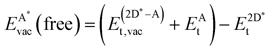
We employ density functional theory11 in our simulations of solvation and adsorption of atoms, small molecules and the monolayers of the relaxed system on the given (111) or (0001) close packed surfaces. In the case of Co we report here the values at the surface Co(0001); the corresponding values on the surface of the high-temperature phase Co(111) are given in the ESI.†As atomic sites we distinguish octahedral (oct) and tetrahedral (tet) sites in the bulk, face centered cubic (fcc), hexagonally close packed (hcp), on top (top) and bridge (bri) sites. Below hcp hollow sites a substrate atom is found in the second substrate layer, and below fcc hollow sites no atom is found in the second substrate layer. On top sites are on top of the atoms in the first substrate layer. Bridge sites are located laterally between the fcc and the hcp sites. Fig. 1 demonstrates the labelling of the investigated atomic sites in the bulk and on the surface, and the nomenclature of the calculated structures of different agglomerates studied with an example of each type, from which other configurations may be inferred. In the case of the vacancies in the (1 × 1) layers the defect site ĀB indicates the registry of the type of atoms A and B, with the vacancy of type A and the site of species B with the lowest energy  in the strained layer. The value of
  is the energy difference between the strained and the free standing layers which have the highest vacancy defect energies.
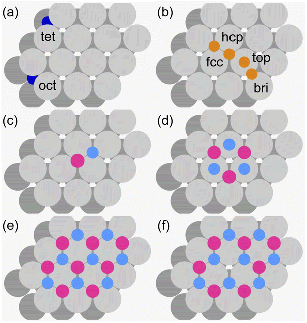 | ||
Fig. 1 Nomenclature of the atomic sites and sketches of the investigated structures. Two stacked hexagonally close packed layers are shown, the first layer in light and the second layer in dark grey. (a) Bulk octahedral (oct) and tetrahedral (tet) interstitial sites (dark blue) as they are encountered between two hexagonally close packed atomic layers. (b) Surface face centred cubic (fcc), hexagonally close packed (hcp), on top (top) and bridge (bri) sites (dark yellow). (c) Example of a dimer, at the registry (B, N) = (fcc, hcp) (B pink, N blue). (d) Example of a ring-hexamer, (B, N) = (hcp, top). (e) A (1 × 1) layer at the registry (B, N) = (fcc, hcp). (f) Example of a B vacancy defect (![[B with combining macron]](https://www.rsc.org/images/entities/char_0042_0304.gif) N) = (fcc, hcp). N) = (fcc, hcp). | ||
We applied a van der Waals functional12 as the approximation of the exchange–correlation term in the Kohn–Sham equations.
We used a 4 × 4 × 4 super-cell of simple cubic shape, yielding 256 atoms (257 with the solvated atom) in the calculations of solvation into the bulk, and either (1 × 1) – commensurate monolayer –, (3 × 3) – adsorbed single atoms and dimers, and vacancies – or (5 × 5) – hexamers – laterally in the calculations of the adsorption energies. Five layers of the substrate were used, with the two top most layers relaxed, in the slab geometry. The lateral size was set by the computer resources, as the computations were repeated on 12 different surfaces plus the Co(111), with several adsorption configurations on each of them.
Here we collect the definitions of the quantities that we used to analyse the energetics. We denote the total energies with the sub-script t, and all the other quantities are energy differences.
The solvation energy EAsol was calculated from
 | (1) |
The adsorption energy EAads of an atom A on a surface was defined as
 | (2) |
The diffusion barrier EAdiff of adsorbate A was calculated from
 | (3) |
 is the third lowest adsorption energy of the four calculated adsorption sites, as it can be shown that this corresponds to the lowest energy needed to diffuse A from its preferred adsorption site into the next cell on the hexagonal surfaces.
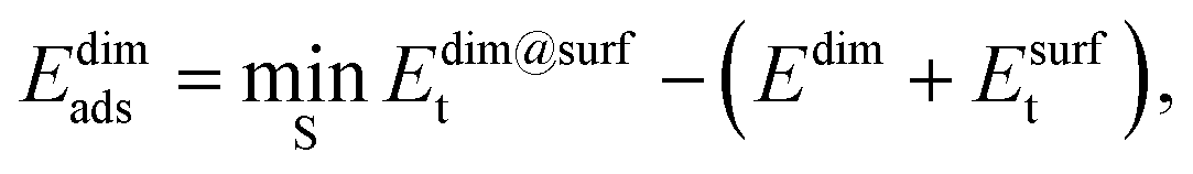
The adsorption energy of the dimer, Edimads, was calculated from
 | (4) |
The bond dissociation energy of the dimer on the surface, EABdiss, was determined from
| EABdiss = (EAads + EBads) − (Edimads − Edimdiss), | (5) |
The adsorption energies of the ring-hexamers, Ehexads, were calculated similarly from
 | (6) |
| Ehex6bo = ((3EAads + 3EBads) − (Ehexads + Ehexdiss))/6, | (7) |
The adsorption energy of strained graphene or hexagonal boron nitride,  , was determined from
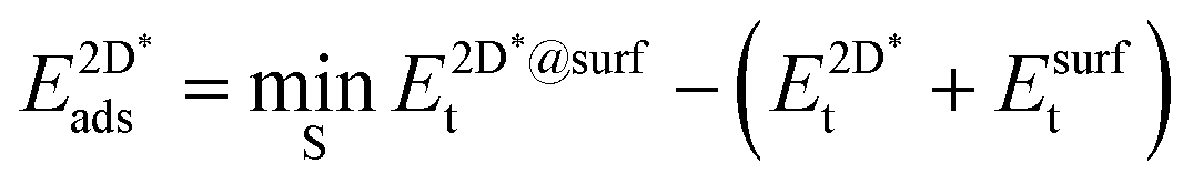 | (8) |
The super-script * is used to denote that the system is under strain due to the use of the same lattice constant on the graphene and h-BN as the lateral lattice constant of the underlying substrate. We again allowed the sites S among the three-fold symmetric fcc, hcp and top, yielding three and six different site arrangements, respectively, in the case of graphene and h-BN.
The effective sp2 bond energy,  , was defined as
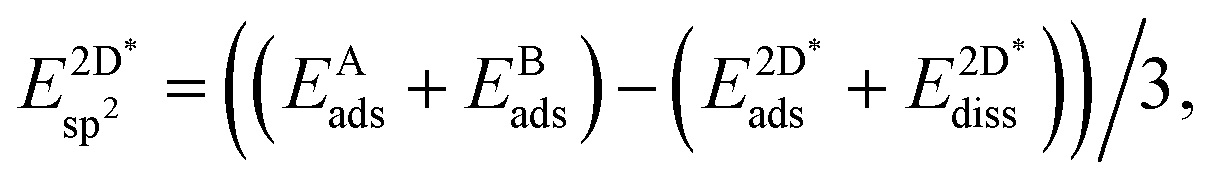 | (9) |
 was calculated at the value of the lateral lattice constant of the underlying substrate even if the substrate has been removed. As a comparison we give the value also in the case of the free-standing 2D layer, where the value corresponds to the negative of the cohesive energy of the monolayer.
The formation energy of a vacancy of an atom of type A,  , was calculated from
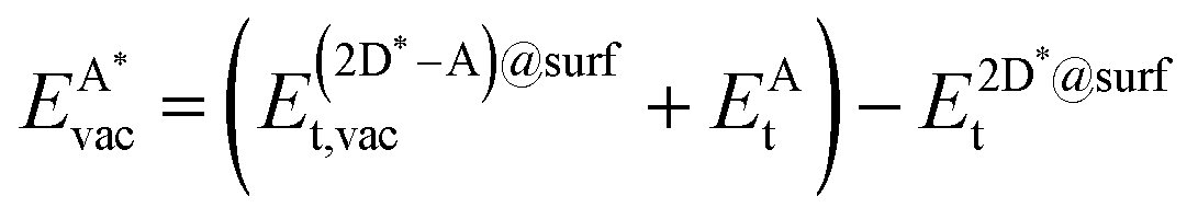 | (10) |
The registry of the monolayer was taken as the lowest-energy one, because from test calculations we saw that this requires the lowest amount of energy to create the vacancy, and it is in any case the preferred configuration without the defect. In the case of graphene the C atom with the lower ECvac was chosen for the analysis.
The formation of a mono-vacancy in the free standing 2D layer was defined as
 | (11) |
 , as
, as | (12) |
3. Results and discussion
Before presenting the results of the calculations the concepts epiphilicity and epiphobicity are outlined. They are important quantities in order to predict the behaviour of a given metal substrate for the growth of 2D materials.3.1. Epiphilic vs. epiphobic
For the prediction of the growth scenarios it is essential to know whether the reaction proceeds on the surface alone, or whether educts may dissolve or solvate into the bulk, and to judge the segregation behaviour. As we learn from effective medium theory,14,15 the dissolution into the bulk must not be the lowest energy state, as there are systems in which the electron density is too high in the bulk, and where an atom finds the optimal electron density rather on a surface, between the bulk and the vacuum. This we call an epiphilic atom/substrate system. The epiphilic and its counterpart, the epiphobic scenario, are depicted in Fig. 2.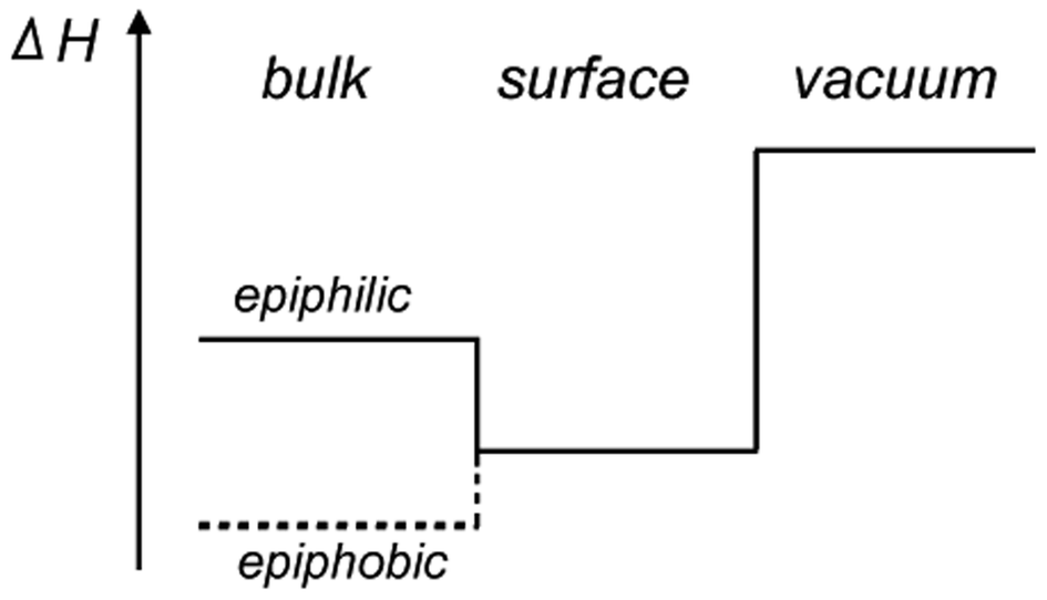 | ||
| Fig. 2 Scheme of the enthalpies ΔH involved in gas–solid reactions. In the epiphilic case the reactant has the lowest energy at the surface, while for the epiphobic case, the dissolution into the bulk is energetically favourable. | ||
In the following we will recall the solvation energies of atoms, before the energies of atoms and their agglomerates on surfaces are described.
3.2. Atom solvation
The calculated solvation energies EAsol of B, C and N in three transition metals are in good agreement with the previously published results on dissolution energies into the bulk.13Fig. 3 shows the adopted dissolution energies with reference to the corresponding atoms in a vacuum. N has the lowest dissolution energy in all the investigated materials. Except for Ir, Pt and Au, C has the highest dissolution energy. B dissolution supersedes the one of N in all the investigated metals, and the dissolution energy in Pd is particularly large.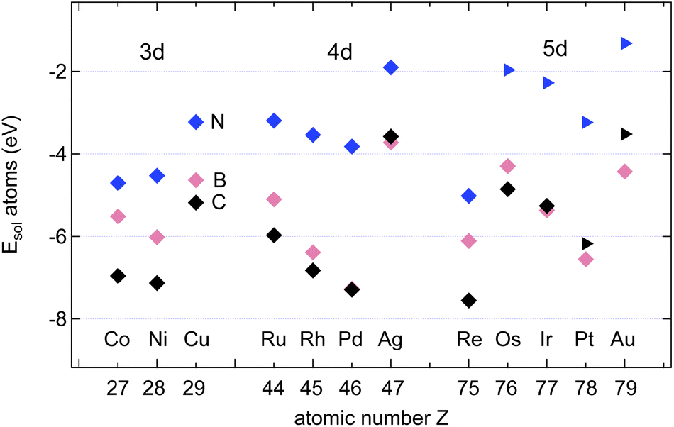 | ||
| Fig. 3 Calculated solvation energies EAsol, A = B (pink), N (blue) and C (black) into the bulk of 12 different transition metals as a function of their atomic numbers. The symbols depict the octahedral ⋄ or tetrahedral ▷ sites. Data adapted from ref. 13. | ||
3.3. Atom adsorption
Fig. 4 shows the calculated adsorption energies of B, C and N atoms on 12 investigated 3d, 4d and 5d transition metal surfaces; they are also listed in Table 1. It is seen that the ECads supersedes that of B and N, where only in the case of Au(111) does B bind more strongly than C, namely by 100 meV, or 2%. This is an important hint that C contamination should be avoided if pure h-BN shall be grown at high temperatures.10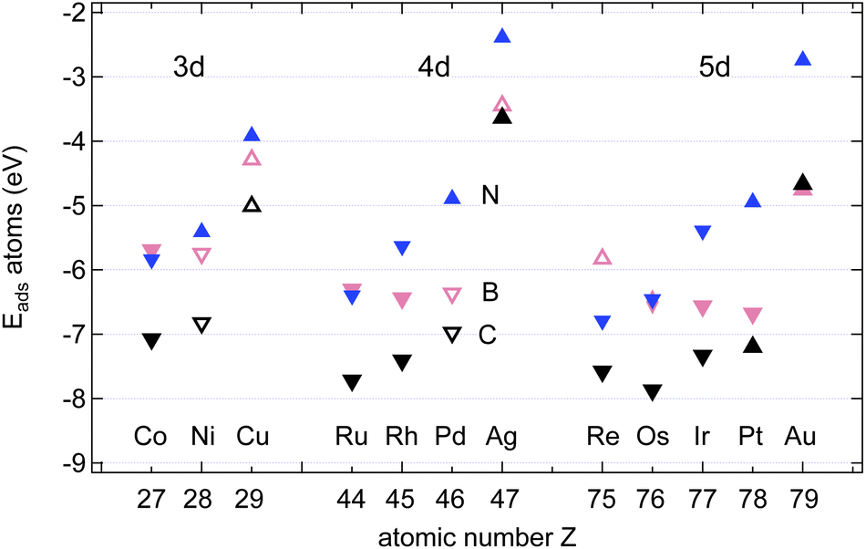 | ||
| Fig. 4 The strongest adsorption energies EAads, A = B (pink), C (black) and N (blue), on transition metal surfaces. The symbols depict the preferred adsorption site: △ = fcc; ▽ = hcp; ◊ = bridge. Full symbols are used in epiphilic and open symbols in epiphobic cases. | ||
| Adsorbate | Substrate | E Asol | Site | E Aads | Site | E Adiff |
|---|---|---|---|---|---|---|
| H | Co | −2.99 | fcc | 0.16 | ||
| Ni | −2.98 | fcc | 0.14 | |||
| Cu | −2.69 | fcc, hcp | 0.13 | |||
| Ru | −3.04 | fcc | 0.14 | |||
| Rh | −2.98 | fcc | 0.11 | |||
| Pd | −2.99 | fcc | 0.13 | |||
| Ag | −2.28 | fcc, hcp | 0.11 | |||
| Re | −3.10 | fcc | 0.19 | |||
| Os | −2.92 | fcc | 0.09 | |||
| Ir | −2.94 | top | 0.11 | |||
| Pt | −2.93 | top | 0.06 | |||
| Au | −2.32 | fcc | 0.05 | |||
| B | Co | −5.51 | oct | −5.69 | hcp | 0.16 |
| Ni | −6.02 | oct | −5.75 | hcp | 0.23 | |
| Cu | −4.63 | oct | −4.29 | fcc | 0.03 | |
| Ru | −5.10 | oct | −6.30 | hcp | 0.50 | |
| Rh | −6.39 | oct | −6.44 | hcp | 0.45 | |
| Pd | −7.27 | oct | −6.36 | hcp | 0.39 | |
| Ag | −3.72 | oct | −3.45 | fcc | 0.12 | |
| Re | −6.11 | oct | −5.83 | fcc | 0.20 | |
| Os | −4.30 | oct | −6.50 | hcp | 0.65 | |
| Ir | −5.37 | oct | −6.56 | hcp | 0.55 | |
| Pt | −6.55 | oct | −6.68 | hcp | 0.43 | |
| Au | −4.42 | oct | −4.75 | fcc | 0.27 | |
| C | Co | −6.96 | oct | −7.07 | hcp | 0.35 |
| Ni | −7.13 | oct | −6.83 | hcp | 0.38 | |
| Cu | −5.18 | oct | −5.01 | fcc | 0.10 | |
| Ru | −5.97 | oct | −7.72 | hcp | 0.77 | |
| Rh | −6.82 | oct | −7.41 | hcp | 0.64 | |
| Pd | −7.29 | oct | −6.97 | hcp | 0.43 | |
| Ag | −3.58 | oct | −3.64 | fcc | 0.23 | |
| Re | −7.55 | oct | −7.58 | hcp | 0.45 | |
| Os | −4.85 | oct | −7.87 | hcp | 0.91 | |
| Ir | −5.26 | oct | −7.33 | hcp | 0.71 | |
| Pt | −6.17 | tet | −7.20 | fcc | 0.34 | |
| Au | −3.51 | tet | −4.67 | fcc | 0.26 | |
| N | Co | −4.70 | oct | −5.84 | hcp | 0.52 |
| Ni | −4.53 | oct | −5.41 | fcc | 0.50 | |
| Cu | −3.22 | oct | −3.92 | fcc | 0.28 | |
| Ru | −3.19 | oct | −6.40 | hcp | 0.89 | |
| Rh | −3.54 | oct | −5.63 | hcp | 0.67 | |
| Pd | −3.82 | oct | −4.89 | fcc | 0.43 | |
| Ag | −1.90 | oct | −2.39 | fcc | 0.28 | |
| Re | −5.02 | oct | −6.79 | hcp | 0.74 | |
| Os | −1.96 | tet | −6.45 | hcp | 1.05 | |
| Ir | −2.27 | tet | −5.39 | hcp | 0.68 | |
| Pt | −3.23 | tet | −4.95 | fcc | 0.32 | |
| Au | −1.31 | tet | −2.74 | fcc | 0.28 | |
| O | Co | −5.84 | hcp | 0.38 | ||
| Ni | −5.49 | fcc | 0.50 | |||
| Cu | −4.87 | fcc | 0.33 | |||
| Ru | −6.15 | hcp | 0.69 | |||
| Rh | −5.25 | fcc | 0.50 | |||
| Pd | −4.51 | fcc | 0.43 | |||
| Ag | −3.72 | fcc | 0.29 | |||
| Re | −6.86 | hcp | 0.86 | |||
| Os | −6.02 | hcp | 0.77 | |||
| Ir | −4.93 | fcc | 0.45 | |||
| Pt | −4.39 | fcc | 0.39 | |||
| Au | −3.31 | fcc | 0.26 |
The adsorption of atoms is weakest on the coinage metals Ag, Cu, and Au and it increases steadily with the number of holes in the d-bands in the case of N.
For the growth of BN we find, except on Co, Ru, and Re, that B binds stronger than N. In contrast to N, the binding of B does not increase steadily with the number of the d-holes but it is the strongest on Pt. The almost degenerate adsorption energies for B and N on Co, Ru and Os are of interest if the stoichiometry of the precursor molecules shall be maintained during the growth process. The dissolution into the bulk has, however, to be considered, even if Ru, and Os are epiphillic for both B and N. For the growth of h-BN without the presence of C we expect on most substrates B enrichment. On Cu(111) at a temperature of 1200 K an equilibrium off stoichiometry factor γEOSF = exp[−(ENads − EBads)/(kBT)] of 46 is found, which predicts a significant B enrichment. While N is epiphilic on all the substrates, with ENads/ENsol between 1.2 (Ni) and 3.3 (Os), B may be both, either epiphilic or epiphobic, with EBads/EBsol between 3.3 (Os) and 0.88 (Pd).
In the growth of homoatomic graphene, with a CC basis, the substrate with the largest relative epiphilicy ECads/ECsol of 1.6 is Au, and that with the highest epiphobicity ECads/ECsol of 0.96 is Pd.
3.4. Surface diffusion of the atoms
The data in Table S2 in the ESI† provide the site-dependence of the adsorption energies and thus allow the determination of an activation energy or energy barrier for diffusion. Four different sites in the unit cell were calculated. When the adsorbate is most stable on a hollow adsorption site, the bridge site is assumed to be the saddle point upon diffusion, and the energy barrier of diffusion EAdiff is defined as the energy difference between the adsorbate on the bridge site and the preferred hollow site. When the preferred adsorption site is the bridge site, the diffusion barrier is defined as the energy difference between the less bound hollow site and the bridge site. These instances correspond to taking the energy difference between the energy at the third-lowest of the four sites and at the strongest adsorption site (Fig. 5).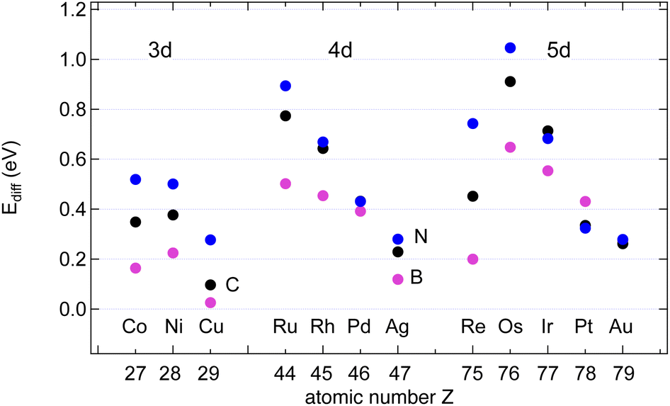 | ||
| Fig. 5 Diffusion barriers EAdiff, A = B (pink), C (black) and N (blue), on the studied surfaces. | ||
Except for the coinage metals on most of the investigated surfaces the adsorption site with the highest binding energy is the hcp site, where in the second substrate layer an atom is located.
The results may be rationalised with the Evans–Polanyi relation stating that EAdiff is smaller and proportional to EAads.16 The proportionality factors are in the order of 10%, though they depend on the adsorbate: From the data in Table 1 follows Ediff/Eads of about 6, 7 and 11% for B, C and N, respectively, on the 12 substrates. In the specific example of B or N on Ni(111) we find EB/Nidiff = Ebriads − Ehcpads = 0.21 eV or 4% of the adsorption energy Eads and EN/Nidiff = Ebriads − Efccads = 0.50 eV, or 9%, respectively. This predicts that B diffuses faster than N. The lower absolute and relative B diffusion barriers appear as a general trend on all the investigated surfaces. On Cu, with EBdiff = 26 meV, the diffusion of B appears to be particularly fast. Notably, this diffusion barrier of B is lower than that of H on all investigated surfaces. In general also C diffuses slower than B, but faster than N.
3.5. C2 and BN dimers
In the next step, we calculated C2 and BN dimers on the surfaces, and the results are shown in Fig. 6 and Table 2. On all the investigated substrates BN preferentially binds with the B closer to the metal than N, and C2 binds stronger than the BN dimer.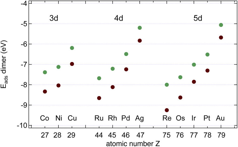 | ||
| Fig. 6 Dimer adsorption energies Edimads, dim = CC (brown) or BN (green), with respect to the dimers in the gas phase. | ||
| Substrate | E CCads | E CCdiss | Site | E BNads | E BNdiss | Site |
|---|---|---|---|---|---|---|
| Gas phase | — | 6.00 | — | — | 4.62 | — |
| Co | −8.34 | 0.19 | fcc, hcp | −7.39 | 0.48 | hcp, fcc |
| Ni | −8.03 | 0.38 | fcc, hcp | −7.12 | 0.64 | hcp, fcc |
| Cu | −6.98 | 2.96 | fcc, hcp | −6.19 | 2.61 | hcp, fcc |
| Ru | −8.66 | −0.77 | fcc, hcp | −7.68 | −0.40 | hcp, fcc |
| Rh | −8.12 | −0.70 | fcc, hcp | −7.21 | −0.24 | hcp, fcc |
| Pd | −7.24 | −0.71 | fcc, hcp | −6.49 | −0.15 | hcp, fcc |
| Ag | −5.83 | 4.56 | fcc, hcp | −5.20 | 3.98 | hcp, fcc |
| Re | −9.25 | 0.10 | fcc, hcp | −8.27 | 0.28 | fcc, hcp |
| Os | −8.63 | −1.11 | fcc, hcp | −7.63 | −0.70 | hcp, fcc |
| Ir | −7.85 | −0.81 | fcc, hcp | −7.01 | −0.32 | hcp, fcc |
| Pt | −7.30 | −1.09 | fcc, hcp | −6.51 | −0.49 | hcp, fcc |
| Au | −5.67 | 2.34 | fcc, hcp | −5.06 | 2.18 | hcp, fcc |
As can be seen from a comparison between the data in Tables 1 and 2 BN dimers binds stronger to the substrate than a N atom, and only on Pd and Pt B binds a little bit stronger than BN. For C2 there is no exception to the rule that the dimer binds stronger than one monomer.
The data suggest that all investigated surfaces greatly reduce the C2 and the BN dissociation energy from that in a vacuum (6.00 and 4.62 eV respectively). On Ru, Rh, Pd, Os, Ir and Pt ECCdiss is even negative, i.e. on these surfaces the dissociated state is more stable than the dimer state. The sign of the C2 dissociation energies on Cu17 and Ir18 has been reported in the literature and agrees with the present study. On Rh, Pd, Ir and Pt EBNdiss is negative, i.e. on these surfaces the dissociated state is more stable than the dimer state. Positive dissociation energies as e.g. for Cu signify an energy gain upon B–N association. This has implications if it comes to the seed formation for graphene and h-BN formation.
The data in Tables 1 and 2 further suggest that the desorption of C is not expected to proceed preferentially via the C2 association and desorption channel. On all the investigated substrates the C2 adsorption energies are larger than the C adsorption energy, and ECCdiss and is smaller than the desorption energy, which indicates that depletion via C2 desorption is unlikely. For B and N, as well, desorption is not expected to proceed preferentially via the dimer channel. On all investigated substrates, the BN adsorption energies are larger than B or N adsorption energy, and EBNdiss is smaller than the desorption energy, which indicates that depletion via BN desorption is unlikely.
3.6. C6 and (BN)3 ring-hexamers
While dimers have no isomers, the hexamers display a variety of possible molecular configurations. In the case of (BN)3 on Cu(111) four different isomers have been investigated, where the linear isomer displayed the lowest energy, lower than that of the hexamer forming a ring.19 In the present article we restrict ourselves to the ring-hexamers, which have the same rotational symmetry as the substrates and the 2D materials gr and h-BN.In Table 3 the adsorption energies of the C6 and (BN)3 ring-hexamers and the corresponding C–C and B–N bond energies are summarised. The atomisation energies of the molecules C6 and (BN)3 in the gas phase are 34.30 and 32.20 eV, respectively, which result in single bond-dissociation energies of 5.72 and 5.37 eV. Compared to the dimers the adsorption energies decrease. Also the single bond energies Ehex6bo of the ring-hexamers are smaller than the C–C and the B–N bond energies EABdiss in the dimers. As for the dimers, there are substrates where the dissociated state is favoured. On these substrates like Ru, it may be concluded that ring-hexamers on terraces are not stable nuclei for the growth of the 2D layers.
| Substrate |
|
E CC6bo | Site |
|
E BN6bo | Site |
|---|---|---|---|---|---|---|
| Gas phase | — | 5.72 | — | — | 5.37 | |
| Co | −7.91 | −0.04 | fcc, hcp | −4.28 | 0.32 | hcp, fcc |
| Ni | −7.07 | 0.07 | fcc, hcp | −3.81 | 0.42 | hcp, fcc |
| Cu | −4.15 | 1.40 | fcc, hcp | −1.87 | 1.58 | fcc, hcp |
| Ru | −7.74 | −0.71 | fcc, hcp | −4.70 | −0.20 | hcp, top |
| Rh | −6.05 | −0.68 | fcc, hcp | −4.29 | 0.05 | hcp, top |
| Pd | −5.41 | −0.36 | hcp, top | −3.57 | 0.33 | hcp, top |
| Ag | −2.28 | 2.46 | hcp, top | −0.78 | 2.58 | fcc, top |
| Re | −8.82 | −0.39 | fcc, hcp | −4.66 | −0.16 | fcc, hcp |
| Os | −6.54 | −1.06 | fcc, top | −5.07 | −0.26 | hcp, top |
| Ir | −5.75 | −0.65 | fcc, top | −4.52 | 0.14 | hcp, top |
| Pt | −5.66 | −0.54 | hcp, top | −3.98 | 0.22 | hcp, top |
| Au | −2.76 | 1.51 | hcp, top | −0.94 | 1.78 | top, hcp |
3.7. (1 × 1) commensurate graphene and h-BN
As can be seen from Tables 2 and 3 the dimers and ring-hexamers are not stable on all the investigated metal surfaces. Yet graphene and h-BN single layers may be grown also on such metals like Ru,20,21 on which the dimers and the ring-hexamers are not stable. This suggests that the growth seeds in cases of a negative hexamer dissociation energy are larger than six atoms. In the case of graphene on Ir(111) the graphene seed size was worked out theoretically to be about 16 C atoms before the energy per C atom becomes lower than that of the single atom adsorbed on Ir and it was shown that atomic steps reduce the seed barrier, though not the seed size.18 On substrates with a large lattice mismatch to graphene and h-BN as it is the case for the 4d and 5d metals the issue of the commensurability and the size of the unit cell emerges. For example, h-BN on Ru forms a 14 on 13 coincidence lattice, which reduces the tensile stress in the h-BN, as found by surface X-ray diffraction.22 The situation of the graphene systems is more involved, as for example a 25 on 23 superstructure has been observed23 and simulated with calculations.24In the present account we did not perform calculations in the large supercells, but on (1 × 1) unit cells with the lattice constant of the substrate. Accordingly, the calculated (1 × 1) adsorption energies neglect the dislocation of the graphene or h-BN layer in a super cell. In Fig. 7 the calculated adsorption energies of strained graphene and h-BN are shown. All metals favour adsorption. There is a clear trend in the adsorption energies with the number of valence band d-holes in the substrate atoms, as has been reported on h-BN by Laskowski et al.25 The increase of the effect in going from the 3d to the 5d transition metals is also seen in the trends of the adsorption energies of the N and C atom (Fig. 4). Re displays the largest sp2 effective adsorption energies, where the h-BN adsorption energy is particularly strong. When we calculated the adsorption energies with respect to the relaxed graphene and h-BN in the gas phase some systems with a large lattice mismatch were not stable as commensurate (1 × 1) systems because the elastic strain energy of (1 × 1) commensurate layers is substantial.
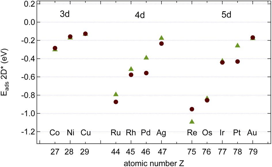 | ||
Fig. 7 Calculated energies  of graphene (brown circles) and h-BN (green triangles) on the studied surfaces. The energy reference is graphene or h-BN strained to the lattice constant of the corresponding transition metal. Except for Re (B, N = C, C = hcp, top) and Au (B, N = C, C = top, fcc) all registries are (B, N = C, C = fcc, top). of graphene (brown circles) and h-BN (green triangles) on the studied surfaces. The energy reference is graphene or h-BN strained to the lattice constant of the corresponding transition metal. Except for Re (B, N = C, C = hcp, top) and Au (B, N = C, C = top, fcc) all registries are (B, N = C, C = fcc, top). | ||
Table 4 shows the adsorption energies and the effective sp2 bond energies of graphene and h-BN in (1 × 1) structures on the investigated transition metals. All effective bond energies are positive, which confirms the stability of the 2D layers.
 , and effective sp2 bond energies
  on the studied surfaces. Energies are given in (eV per (1 × 1) unit cell) and (eV per bond)
| Substrate | E grads |
|
Site CC | E h-BNads |
|
Site BN |
|---|---|---|---|---|---|---|
| Free standing | — | 5.17 | — | — | 4.63 | — |
| Co | −0.28 | 0.55 | top, fcc | −0.30 | 0.88 | fcc, top |
| Ni | −0.16 | 0.67 | top, fcc | −0.17 | 0.96 | fcc, top |
| Cu | −0.13 | 1.87 | top, fcc | −0.13 | 1.94 | fcc, top |
| Ru | −0.87 | 0.32 | top, fcc | −0.79 | 0.66 | fcc, top |
| Rh | −0.58 | 0.42 | top, fcc | −0.52 | 0.78 | fcc, top |
| Pd | −0.56 | 0.71 | top, fcc | −0.39 | 1.00 | fcc, top |
| Ag | −0.23 | 2.82 | top, fcc | −0.17 | 2.74 | fcc, top |
| Re | −0.95 | 0.44 | top, hcp | −1.09 | 0.79 | hcp, top |
| Os | −0.86 | 0.21 | top, fcc | −0.84 | 0.59 | fcc, top |
| Ir | −0.44 | 0.43 | top, fcc | −0.43 | 0.78 | fcc, top |
| Pt | −0.43 | 0.52 | top, fcc | −0.26 | 0.84 | fcc, top |
| Au | −0.17 | 2.12 | top, fcc | −0.18 | 2.19 | top, fcc |
In the ESI†, graphs are shown in Fig. S1† that summarise the solvation and the different adsorption energies of the graphene and boron nitride systems on the investigated substrates.
3.8. Vacancy defect energies
If the ultimate thermal stability of graphene or h-BN shall be predicted, the formation energy of single atomic vacancies is a key quantity.4 In Table 5 the calculated vacancy defect energies for strained graphene and h-BN on the twelve different metal substrates are given. From the the Cu substrate has the highest stability of graphene and h-BN. Another general observation is that in the case of h-BN nitrogen has a lower vacancy formation energy than boron. This is important information if single photon emitters based on h-BN shall be grown.26 In the ESI, Table S8† further contains the energetics referred to as the chemical potential of the atoms in the single layer instead of free atoms as used here; those values can be used for example to calculate the equilibrium concentration of vacancies.
| Substrate |
|
|
Site ![[C with combining macron]](https://www.rsc.org/images/entities/char_0043_0304.gif) C C |
|
|
Site N |
|
|
Site B![[N with combining macron]](https://www.rsc.org/images/entities/char_004e_0304.gif) |
|---|---|---|---|---|---|---|---|---|---|
| Free standing, unstrained | 15.61 | 0 | — | 16.13 | 0 | — | 13.07 | 0 | — |
| Co | 10.01 | 5.64 | top, fcc | 11.83 | 4.31 | fcc, top | 8.49 | 4.14 | fcc, top |
| Ni | 10.37 | 5.27 | top, fcc | 11.82 | 4.31 | fcc, top | 8.59 | 3.95 | fcc, top |
| Cu | 12.48 | 3.01 | top, fcc | 12.43 | 3.61 | fcc, top | 11.14 | 2.17 | fcc, top |
| Ru | 8.74 | 4.78 | top, fcc | 9.33 | 5.00 | fcc, top | 8.24 | 4.91 | fcc, top |
| Rh | 8.53 | 5.24 | top, fcc | 9.74 | 4.82 | fcc, top | 8.14 | 5.13 | fcc, top |
| Pd | 8.59 | 3.89 | top, fcc | 9.20 | 4.18 | fcc, top | 7.21 | 5.38 | fcc, top |
| Ag | 6.17 | 2.84 | top, fcc | 6.29 | 4.41 | fcc, top | 7.81 | 2.96 | fcc, top |
| Re | 7.18 | 5.39 | top, hcp | 9.24 | 4.22 | hcp, top | 8.15 | 4.48 | hcp, top |
| Os | 8.36 | 4.55 | top, fcc | 8.38 | 5.38 | fcc, top | 7.66 | 5.17 | fcc, top |
| Ir | 7.85 | 5.32 | top, fcc | 8.38 | 5.63 | fcc, top | 7.40 | 5.57 | fcc, top |
| Pt | 7.37 | 4.57 | top, fcc | 7.75 | 5.17 | fcc, top | 5.73 | 6.55 | fcc, top |
| Au | 5.94 | 2.49 | top, fcc | 7.88 | 2.44 | top, fcc | 6.44 | 4.08 | top, fcc |


The results in Fig. 8 display the lowering of the vacancy defect creation energies with respect to the strained free standing layers  in the strained adsorbed layers. In the case of gr/Ir(111) defect formation energies in a (10 × 10) on (9 × 9) supercell have been calculated and found to depend on the registry of the C atoms with respect to the Ir atoms.27 From these energies we derive values of ΔEvac between 1.7 and 3.0 eV. They compare to 5.32 eV from the present calculation of the strained graphene. In the case of h-BN/Rh(111) defect formation energies in the whole (13 × 13) on (12 × 12) supercell have been calculated in order to explain the so called “can-opener” effect.28 From this we derive values of
  between 2.57 and 5.96 eV for B and between 1.56 and 4.43 eV for N. They compare to 4.82 and 5.15 eV in the present calculation for B and N, respectively, of strained h-BN vs. strained h-BN/Rh(111). The present vacancy formation energies may therefore be considered as upper bounds, as in a larger unit cell lower vacancy defect formation energies may be expected.
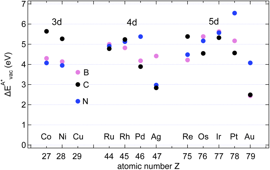 | ||
Fig. 8 Vacancy defects. The  is the lowering of the vacancy defect creation energy in the strained adsorbed layer, compared to the strained free-standing layer. For graphene (black dots) the defect with the higher is the lowering of the vacancy defect creation energy in the strained adsorbed layer, compared to the strained free-standing layer. For graphene (black dots) the defect with the higher  is displayed. The particularly low is displayed. The particularly low  on Au is due to the fact that the gold atom beneath the vacancy lifts out of the substrate and accordingly increases the energy of the system with the vacancy on the substrate. on Au is due to the fact that the gold atom beneath the vacancy lifts out of the substrate and accordingly increases the energy of the system with the vacancy on the substrate. | ||
4. Conclusions
The present article reports comprehensive sets of calculated energies of atomic systems as they are encountered in the growth of graphene and hexagonal boron nitride on twelve different transition metals. Solvation, adsorption and diffusion energies for single atoms are presented. This database forms a guideline for the expected processes. For the growth of 2D materials the surface adsorption energies of dimers and ring-hexamers and their stability as seeds were calculated. The stability of the sp2 layers was estimated from the vacancy creation energies.From the trends above, criteria for the rational design of high quality and stability graphene and h-BN on transition metals have become available.
Author contributions
The manuscript was written through the contributions of both authors. T. G. initiated the project and wrote the first version of the manuscript. APS performed the calculations, cross checked and inserted the results in the tables.Conflicts of interest
There are no conflicts to declare.Acknowledgements
We acknowledge financial support from the Swiss National Science Foundation (SNF project no. 200020_201086) and by the European Commission under the Graphene Flagship (contract no. CNECT-ICT-604391). We further acknowledge access to Piz Daint and Eiger@Alps at the Swiss National Supercomputing Centre (CSCS), Switzerland under the share of the Universität Zürich with the project ID uzh11.Notes and references
- L. Zhang, J. Dong and F. Ding, Chem. Rev., 2021, 121, 6321–6372 CrossRef CAS PubMed.
- T. Zhao, J. Guo, T. Li, Z. Wang, M. Peng, F. Zhong, Y. Chen, Y. Yu, T. Xu, R. Xie, P. Gao, X. Wang and W. Hu, Chem. Soc. Rev., 2023, 52, 1650–1671 RSC.
- K. Y. Ma, L. Zhang, S. Jin, Y. Wang, S. I. Yoon, H. Hwang, J. Oh, D. S. Jeong, M. Wang, S. Chatterjee, G. Kim, A.-R. Jang, J. Yang, S. Ryu, H. Y. Jeong, R. S. Ruoff, M. Chhowalla, F. Ding and H. S. Shin, Nature, 2022, 606, 88–93 CrossRef CAS.
- F. Banhart, J. Kotakoski and A. V. Krasheninnikov, ACS Nano, 2011, 5, 26–41 CrossRef CAS PubMed.
- M. Mavrikakis, J. Rempel, J. Greeley, L. B. Hansen and J. K. Nørskov, J. Chem. Phys., 2002, 117, 6737–6744 CrossRef CAS.
- J. Wintterlin and M. Bocquet, Surf. Sci., 2009, 603, 1841–1852 CrossRef CAS.
- M. Saeed, Y. Alshammari, S. Majeed and E. Al-Nasrallah, Molecules, 2020, 25, 3856 CrossRef CAS PubMed.
- W. Auwärter, Surf. Sci. Rep., 2019, 74, 1–95 CrossRef.
- H. Cun, Z. Miao, A. Hemmi, Y. Al-Hamdani, M. Iannuzzi, J. Osterwalder, M. S. Altman and T. Greber, ACS Nano, 2021, 15, 1351–1357 CrossRef CAS.
- A. Hemmi, A. Seitsonen, T. Greber and H. Cun, Small, 2022, 2205184 CrossRef CAS.
- P. Hohenberg and W. Kohn, Phys. Rev., 1964, 136, B864 CrossRef.
- I. Hamada, Phys. Rev. B: Condens. Matter Mater. Phys., 2014, 89, 121103 CrossRef.
- X. Hu, T. Bjorkman, H. Lipsanen, L. Sun and A. Krasheninnikov, J. Phys. Chem. Lett., 2015, 6, 3263–3268 CrossRef CAS.
- J. K. Nørskov and N. D. Lang, Phys. Rev. B: Condens. Matter Mater. Phys., 1980, 21, 2131–2136 CrossRef.
- M. J. Puska, R. M. Nieminen and M. Manninen, Phys. Rev. B: Condens. Matter Mater. Phys., 1981, 24, 3037–3047 CrossRef CAS.
- M. G. Evans and M. Polanyi, Trans. Faraday Soc., 1938, 34, 11–24 RSC.
- S. Riikonen, A. V. Krasheninnikov, L. Halonen and R. M. Nieminen, J. Phys. Chem. C, 2012, 116, 5802–5809 CrossRef CAS.
- C. Herbig, E. H. Åhlgren, W. Jolie, C. Busse, J. Kotakoski, A. V. Krasheninnikov and T. Michely, ACS Nano, 2014, 8, 12208–12218 CrossRef CAS.
- Z.-Q. Liu, J. Dong and F. Ding, Nanoscale, 2019, 11, 13366–13376 RSC.
- Y. Pan, D.-X. Shi and H.-J. Gao, Chin. Phys., 2007, 16, 3151–3153 CrossRef.
- A. Goriachko, Y. He, M. Knapp, H. Over, M. Corso, T. Brugger, S. Berner, J. Osterwalder and T. Greber, Langmuir, 2007, 23, 2928–2931 CrossRef CAS PubMed.
- D. Martoccia, T. Brugger, M. Björck, C. Schlepütz, S. Pauli, T. Greber, B. Patterson and P. Willmott, Surf. Sci., 2010, 604, L16–L19 CrossRef CAS.
- D. Martoccia, P. R. Willmott, T. Brugger, M. Björck, S. Günther, C. M. Schlepütz, A. Cervellino, S. A. Pauli, B. D. Patterson, S. Marchini, J. Wintterlin, W. Moritz and T. Greber, Phys. Rev. Lett., 2008, 101, 126102 CrossRef CAS PubMed.
- M. Iannuzzi, I. Kalichava, H. Ma, S. J. Leake, H. Zhou, G. Li, Y. Zhang, O. Bunk, H. Gao, J. Hutter, P. R. Willmott and T. Greber, Phys. Rev. B: Condens. Matter Mater. Phys., 2013, 88, 125433 CrossRef.
- R. Laskowski, P. Blaha and K. Schwarz, Phys. Rev. B: Condens. Matter Mater. Phys., 2008, 78, 045409 CrossRef.
- T. T. Tran, K. Bray, M. J. Ford, M. Toth and I. Aharonovich, Nat. Nanotechnol., 2016, 11, 37 CrossRef CAS.
- S. Standop, O. Lehtinen, C. Herbig, G. Lewes-Malandrakis, F. Craes, J. Kotakoski, T. Michely, A. V. Krasheninnikov and C. Busse, Nano Lett., 2013, 13, 1948–1955 CrossRef CAS PubMed.
- H. Y. Cun, M. Iannuzzi, A. Hemmi, J. Osterwalder and T. Greber, ACS Nano, 2014, 8, 7423–7431 CrossRef CAS PubMed.
Footnote |
| † Electronic supplementary information (ESI) available. See DOI: https://doi.org/10.1039/d3na00472d |
| This journal is © The Royal Society of Chemistry 2024 |