
 Open Access Article
 This Open Access Article is licensed under a
 Creative Commons Attribution 3.0 Unported Licence
A disposal-MOX concept for plutonium disposition†
Max R.
Cole
a,
Lewis R.
Blackburn
a,
Latham T.
Haigh
 a,
Daniel J.
Bailey
a,
Luke T.
Townsend
a,
Kristina O.
Kvashnina
bc,
Neil C.
Hyatt
de and
Claire L.
Corkhill
*d
a,
Daniel J.
Bailey
a,
Luke T.
Townsend
a,
Kristina O.
Kvashnina
bc,
Neil C.
Hyatt
de and
Claire L.
Corkhill
*d
aImmobilisation Science Laboratory, Department of Materials Science and Engineering, The University of Sheffield, UK
bHelmholtz-Zentrum Dresden-Rossendorf (HZDR), Institute of Resource Ecology, Germany
cThe Rossendorf Beamline at ESRF – The European Synchrotron, CS40220, 38043 Grenoble Cedex 9, France
dSchool of Earth Sciences and the South West Nuclear Hub, The University of Bristol, UK. E-mail: c.corkhill@bristol.ac.uk
eSchool of Mechanical and Materials Engineering, Washington State University, Pullman, USA
First published on 29th June 2024
Abstract
In case it is desirable to dispose of inventories of separated civil PuO2 that have no further use, a suitable immobilisation matrix is required, prior to disposition in a geological disposal facility. Conversion of Pu into a mixed oxide (MOX)-type material with characteristics suitable for disposal has previously been suggested, but not yet demonstrated at laboratory or industrial scale. We here demonstrate the feasibility of different synthesis routes for simulant “disposal-MOX”, using Th4+ as a Pu4+ surrogate and containing Gd3+ in a suitable quantity to ensure criticality control. Compositions of (U(1−(x+y))ThxGdy)O2−δ, where x = 0.1, 0.2 and x![[thin space (1/6-em)]](https://www.rsc.org/images/entities/i_char_2009.gif) :
:![[thin space (1/6-em)]](https://www.rsc.org/images/entities/char_2009.gif) y = 10:1 or 100:1, were synthesised by a solid state route mimicking the industrial MIMAS (MIcronized MASterblend) MOX fuel fabrication process, or through an oxalic wet co-precipitation method. Both synthesis routes gave a single phase fluorite structure upon heat-treatment at 1700 °C, with a grain size similar to (Pu,U)O2 MOX fuel. The relative density of the sintered pellets was >90% but was highest in co-precipitated materials, with Th4+ and Gd3+ additions more homogenously distributed. Though no unincorporated ThO2 or Gd2O3 was observed in any sample, Th and Gd-rich regions were more prevalent in materials produced through solid state synthesis, in accordance with MIMAS MOX fuel microstructures. The incorporation of Gd3+ within the fluorite lattice, which is favourable from a criticality control perspective in a Pu wasteform, was found to be charge balanced via the generation of oxygen vacancy defects, but not U5+. These results demonstrate feasible synthesis routes for a disposal-MOX wasteform product via both solid state and wet co-precipitation fabrication routes.
y = 10:1 or 100:1, were synthesised by a solid state route mimicking the industrial MIMAS (MIcronized MASterblend) MOX fuel fabrication process, or through an oxalic wet co-precipitation method. Both synthesis routes gave a single phase fluorite structure upon heat-treatment at 1700 °C, with a grain size similar to (Pu,U)O2 MOX fuel. The relative density of the sintered pellets was >90% but was highest in co-precipitated materials, with Th4+ and Gd3+ additions more homogenously distributed. Though no unincorporated ThO2 or Gd2O3 was observed in any sample, Th and Gd-rich regions were more prevalent in materials produced through solid state synthesis, in accordance with MIMAS MOX fuel microstructures. The incorporation of Gd3+ within the fluorite lattice, which is favourable from a criticality control perspective in a Pu wasteform, was found to be charge balanced via the generation of oxygen vacancy defects, but not U5+. These results demonstrate feasible synthesis routes for a disposal-MOX wasteform product via both solid state and wet co-precipitation fabrication routes.
1. Introduction
The United Kingdom's inventory of separated Pu is forecast to reach 141 teHM (tonnes equivalent heavy metal). At present, the long-term management strategy for separated PuO2, as outlined by the Nuclear Decommissioning Authority (NDA), stipulates that this material must be placed ‘beyond reach’.1 One option that could be considered for the whole inventory, should policy dictate, is immobilisation within a ceramic matrix, prior to disposition in a geological disposal facility.2,3Disposal mixed oxide, herein referred to as ‘disposal-MOX’, was originally conceptualised by Macfarlane et al.,4 and termed a ‘low specification MOX’ fuel product – a sintered solid solution of PuO2 and UO2 – without precise constraints on size as would be expected for reactor-grade MOX fuel. In this concept, then called “Plutonium Disposal – the Third Way”, the low-specification MOX would be encapsulated within a vitrified borosilicate high level radioactive waste glass, which would serve as both a source of criticality control through the presence of boron, and also a proliferation barrier due to the high radiation field emanating from the glass.5,6 A simpler and more effective criticality control could be provided by adding a neutron absorbing element to the PuO2 and UO2 blend, e.g., Gd2O3 or HfO2. Given that MOX fuel has been demonstrated at an industrial scale, this route could offer a potentially more appealing industrially-proven option for plutonium disposition when compared with technologically immature titanate ceramic materials fabricated by hot isostatic pressing, which are also being investigated as a potential route for plutonium disposition.7–10 On the other hand, UK implementation of production scale MOX fuel manufacture, in the Sellafield MOX plant, proved problematic.
Oxides of Pu and U adopt the cubic fluorite (Fm![[3 with combining macron]](https://www.rsc.org/images/entities/char_0033_0304.gif) m) structure with comparable lattice dimensions (a = 5.470 Å and 5.398 Å for UO2 and PuO2, respectively). Furthermore, UO2 and PuO2 have similar densities, of 10.97 and 11.50 g cm−3, respectively, and comparable melting points of 2827 °C and 2400 °C. As such, at the elevated temperatures used in wasteform processing (∼1700 °C), there exists a complete solid solution between UO2 and PuO2 (in the form U1−xPuxO2), resulting in a relatively homogenous, single phase material.11 When incorporated within a UO2 solid solution, the neutron absorbing additive Gd2O3, also maintains the fluorite (Fmm) structure, up to 50 mol% Gd,12 which should be significantly above the threshold required to mitigate criticality in management and disposal. Within the context of disposal in a geological facility, the adoption of the fluorite structure is advantageous since it exhibits high tolerance to radiation damage and can readily accommodate He(g) generated through alpha decay.13,14 UO2 and MOX fuels are also known to possess high aqueous durability under reducing conditions.15,16 Moreover, the addition of Gd has been shown to reduce the rate of U release during dissolution.17,18
m) structure with comparable lattice dimensions (a = 5.470 Å and 5.398 Å for UO2 and PuO2, respectively). Furthermore, UO2 and PuO2 have similar densities, of 10.97 and 11.50 g cm−3, respectively, and comparable melting points of 2827 °C and 2400 °C. As such, at the elevated temperatures used in wasteform processing (∼1700 °C), there exists a complete solid solution between UO2 and PuO2 (in the form U1−xPuxO2), resulting in a relatively homogenous, single phase material.11 When incorporated within a UO2 solid solution, the neutron absorbing additive Gd2O3, also maintains the fluorite (Fmm) structure, up to 50 mol% Gd,12 which should be significantly above the threshold required to mitigate criticality in management and disposal. Within the context of disposal in a geological facility, the adoption of the fluorite structure is advantageous since it exhibits high tolerance to radiation damage and can readily accommodate He(g) generated through alpha decay.13,14 UO2 and MOX fuels are also known to possess high aqueous durability under reducing conditions.15,16 Moreover, the addition of Gd has been shown to reduce the rate of U release during dissolution.17,18
To demonstrate the feasibility of a disposal-MOX wasteform for Pu, we herein advance and demonstrate the concept of MacFarlane et al.4via investigation of disposal-MOX materials varying in composition and fabrication route. Oxide precursors were prepared through wet co-precipitation and conventional solid state mixed oxide synthesis routes to assess the influence of homogenisation on the final sintered disposal-MOX materials. The solid state fabrication route was based on the MIMAS (MIcronized MASterblend) process used to fabricate MOX fuel at the MELOX facility in France. This involves blending and milling UO2 and PuO2 powders into a ‘master’ blend before diluting with additional UO2 to achieve the desired U:Pu ratio;19 whereas, in the wet co-precipitation route, oxides were yielded from an oxalic precipitation of nitrate solutions, promoting higher homogeneity and phase purity. Samples were characterised to ascertain the influence of chemical composition and synthesis route on the final sintered microstructure, crystalline defects, distribution of the neutron absorber Gd and Pu surrogate, and oxidation state of U. As Pu is expected to maintain an oxidation state of +4 in disposal-MOX, Th, with its highly stable Th4+ oxidation state, was chosen as a surrogate for these demonstration trials.20
2. Experimental methodology and characterisation
2.1 Material synthesis
Four disposal-MOX compositions were produced, nominally: U0.899Th0.100Gd0.001O2−δ, U0.890Th0.100Gd0.010O2−δ, U0.798Th0.200Gd0.002O2−δ and 0.780Th0.200Gd0.020O2−δ. Th additions of 10 and 20 mol% represent realistic Pu content that could be incorporated within disposal-MOX. Similarly, the 100:1 ratio of Th:Gd reflects a reasoned estimate of the ratio of Pu:Gd required for criticality considerations in disposal environment scenarios. A greater 10:1 ratio was fabricated to investigate the effects of excessive Gd addition and to improve detection of Gd. The four compositions were produced using two distinct fabrication routes, wet co-precipitation, and solid-state mixed oxide synthesis, yielding a total of eight unique samples. Herein, samples will be referred to by their nominally targeted composition, though the reader is referred to Table 1 for measured compositions determined by inductively coupled plasma-optical emission spectroscopy (ICP-OES) following nitric acid digest and electron probe microanalysis (EPMA).
| Synthesis | Target formula | Measured (ICP digest) | Measured (EMPA) |
|---|---|---|---|
| Co-prec. | U0.899Th0.100Gd0.001O2−δ | U0.848(7)Th0.146(7)Gd0.006(2)O2−δ | U0.825(3)Th0.174(2)Gd0.001(1)O2−δ |
| U0.890Th0.100Gd0.010O2−δ | U0.835(5)Th0.131(3)Gd0.034(2)O2−δ | U0.827(3)Th0.165(2)Gd0.008(1)O2−δ | |
| U0.798Th0.200Gd0.002O2−δ | U0.758(1)Th0.234(9)Gd0.008(0)O2−δ | — | |
| U0.780Th0.200Gd0.020O2−δ | U0.666(6)Th0.266(4)Gd0.069(2)O2−δ | U0.655(3)Th0.331(2)Gd0.014(1)O2−δ | |
| Solid state | U0.899Th0.100Gd0.001O2−δ | U0.889(3)Th0.106(3)Gd0.005(1)O2−δ | U0.779(3)Th0.221(3)Gd0.000(1)O2−δ |
| U0.890Th0.100Gd0.010O2−δ | U0.866(3)Th0.105(2)Gd0.029(2)O2−δ | U0.863(3)Th0.130(1)Gd0.007(1)O2−δ | |
| U0.798Th0.200Gd0.002O2−δ | U0.801(4)Th0.192(4)Gd0.008(7)O2−δ | — | |
| U0.780Th0.200Gd0.020O2−δ | U0.759(4)Th0.187(4)Gd0.054(2)O2−δ | — |
Wet co-precipitated samples were prepared through an oxalic precipitation route. Firstly, UO2(NO3)2·6H2O (British Drug House (BDH). B.D.H. Laboratory Chemicals Division, >98%), Th(NO3)4·6H2O (British Drug House (BDH). B.D.H. Laboratory Chemicals Division, >98%) and GdCl3·6H2O (Sigma Aldrich, >99%) were dissolved in 1 M HCl to create solutions of known concentrations. Specific volumes of each solution, corresponding to the target chemical formula shown in Table 1, were mixed with the aid of a magnetic stirrer. The addition of 1 M oxalic acid promoted the instantaneous precipitation of mixed U, Th, and Gd oxalates. The oxalate precipitates were filtered and dried prior to calcination at temperatures ranging from 400 °C to 800 °C under a 5% H2/95% N2 atmosphere, yielding a fine oxide mixture. Approximately 200 mg of oxide powder calcined at 800 °C was pressed within a 6 mm stainless steel die to form loosely densified green bodies. No pore formers were used. Green bodies were placed onto a zirconia crucible and sintered at 1700 °C for 8 hours under a reducing 5% H2/95% N2 gas atmosphere, with a heating and cooling rate of 3 °C min−1.
The solid state mixed oxide synthesis route was devised to resemble the MIMAS (MIcronized MASterblend) process developed by BelgoNucleaire, by which the majority of commercial MOX fuels are fabricated.21 The two-step MIMAS process involves creating a ‘master’ blend of UO2 and PuO2 that is subsequently diluted with UO2 to achieve the desired U:Pu ratio in the final material. For this study, two master blends, corresponding with the two target Th:Gd ratios (1:100 and 1:10), were made by mixing appropriate masses of UO2 (ABSCO Ltd, >98%), ThO2 (decomposed from Th(NO3)4·6H2O, B.D.H. Laboratory Chemicals Division, >98%), and Gd2O3 (Sigma Aldrich, >99.9%) powders. Master blends were produced from constituent oxides via planetary milling, at 500 rpm for 1 h in propan-2-ol, to form a micronized blend that was subsequently sieved to achieve a particle size of less than 200 μm. This material was homogenised with additional UO2 by roller milling for 24 h to yield the desired formulation as per the MIMAS flowsheet.22 Milled, homogenised powders were pressed into green bodies and sintered as above.
2.2 Material characterisation
Thermal analysis was performed on the oxalate precipitates using a Netzsch TG 449 F3 Jupiter thermal analyser. Data was collected from simultaneous thermogravimetric (TG) and differential thermal (DT) analysis, in tandem with mass spectroscopy (MS), while oxalates were heated to temperatures of 1000 °C with a temperature ramp rate of 10 °C min−1. Powder X-ray diffraction (XRD) analysis was performed on all precursors and sintered materials using a Bruker D2 Phaser fitted with a Lynxeye position sensitive detector. Data were acquired using a Cu-Kα source (λ = 1.5418 Å, Ni filter) in the range of 20° ≤ 2θ ≤ 80°, with a step size of 0.02°. Sintered powders were mixed with 10 wt% LaB6 as an internal standard to support lattice parameter refinement performed by the Rietveld method.Elemental concentrations in the sintered products were determined using two methods. Firstly, 20 mg of crushed sintered material was completely dissolved in 2 M HNO3 at 90 °C, over 3 days, with the aid of constant mixing. The resulting solutions were diluted and analysed in triplicate using inductively coupled plasma-optical emission spectroscopy (ThermoFisher iCAPDuo6300) at the PLEIADES facility. External calibration was performed using single element standards (NIST traceable). Secondly, electron probe micro-analysis (EPMA) was undertaken using a JEOL JXA-8530F Plus Hyper Probe with an accelerating voltage of 15 kV and a probe current 100 nA. Compositions were measured using a minimum of five quantitative spot measurements, each at the centre of grains across the surface. Sintered pellets were polished to 1 μm and carbon coated to reduce surface charging effects. EPMA maps were collected for U, Th, Gd and O in stage mode, allowing the probe incident angle to remain constant during measurements to avoid errors associated with interaction volume changes.
Sintered pellet density was determined by the Archimedes method using a Mettler Toledo ME204 balance at room temperature using ethanol as the buoyancy medium. Ten repeat measurements were collected for each sample and the quoted error was calculated using the standard deviation of these measurements. Theoretical densities for each composition were calculated using the refined lattice parameters derived from XRD measurement.
Analysis of powder morphology and pellet microstructure was conducted using a Hitachi TM3030 SEM operating in backscattered electron (BSE) mode. EDS maps of powder samples were collected for a minimum of 10 minutes. Sintered pellets were polished to 1 μm and thermally etched at 1630 °C (90% of sintering temperature) to reveal the grain boundaries, allowing for grain size analysis through morphological segmentation using the MorphoLibJ plug-in suite23 through the Fiji software package.24 A minimum of 500 grains were analysed across several micrographs taken at random across the pellet surface to obtain a statistical average for each sample.
A Renishaw inVia microscope was used to conduct Raman spectroscopy on sintered pellets after polishing and annealing. Five sets of spectra, each of 15 acquisitions, were taken at the centre of grains with a 30 s acquisition time using a 514 nm laser set to 5 mW. These spectra were baseline subtracted, smoothed using the Savitsky–Golay approach and averaged. Deconvolution of Raman spectra was performed using Igor Pro software through the application of Gaussian peaks.
Uranium M4-edge (3.725 keV) high energy resolution fluorescence detection X-ray absorption near edge spectroscopy (HERFD-XANES) was performed at the HZDR ROBL beamline of the European Synchrotron Radiation Facility.25,26 The incident energy (3.725 keV) was selected with a Si(111) double-crystal monochromator and HERFD-XANES spectra were collected using five Si(220) crystal analysers at room temperature. Normalised U5+ content was determined using iterative transformation factor analysis (ITFA) and linear combination fitting (LCF) methods relative to well-characterised U standards. Linear combination fitting (LCF) was performed using Athena27 and the proportion of U4+ and U5+ determined using the ITFA software package.28
3. Results and discussion
3.1 Characterisation of oxalate powders
Oxalate powders of each composition were found to crystallise in the monoclinic space groups P21/c, and C2/c. This is consistent with the precipitation, from solution, of mixed of U and Th oxalate, respectively29 (Fig. 1a). The oxalates adopted a platelet morphology upon precipitation (Fig. 1b and Fig. S1, ESI†), with each platelet measuring ∼5–10 μm in all samples. EDS mapping indicated that each platelet contained a mixture of U, Th and Gd (Fig. 1b), as a homogeneous single oxalate phase, or an intimate mixture of separate U, Th and Gd oxalates.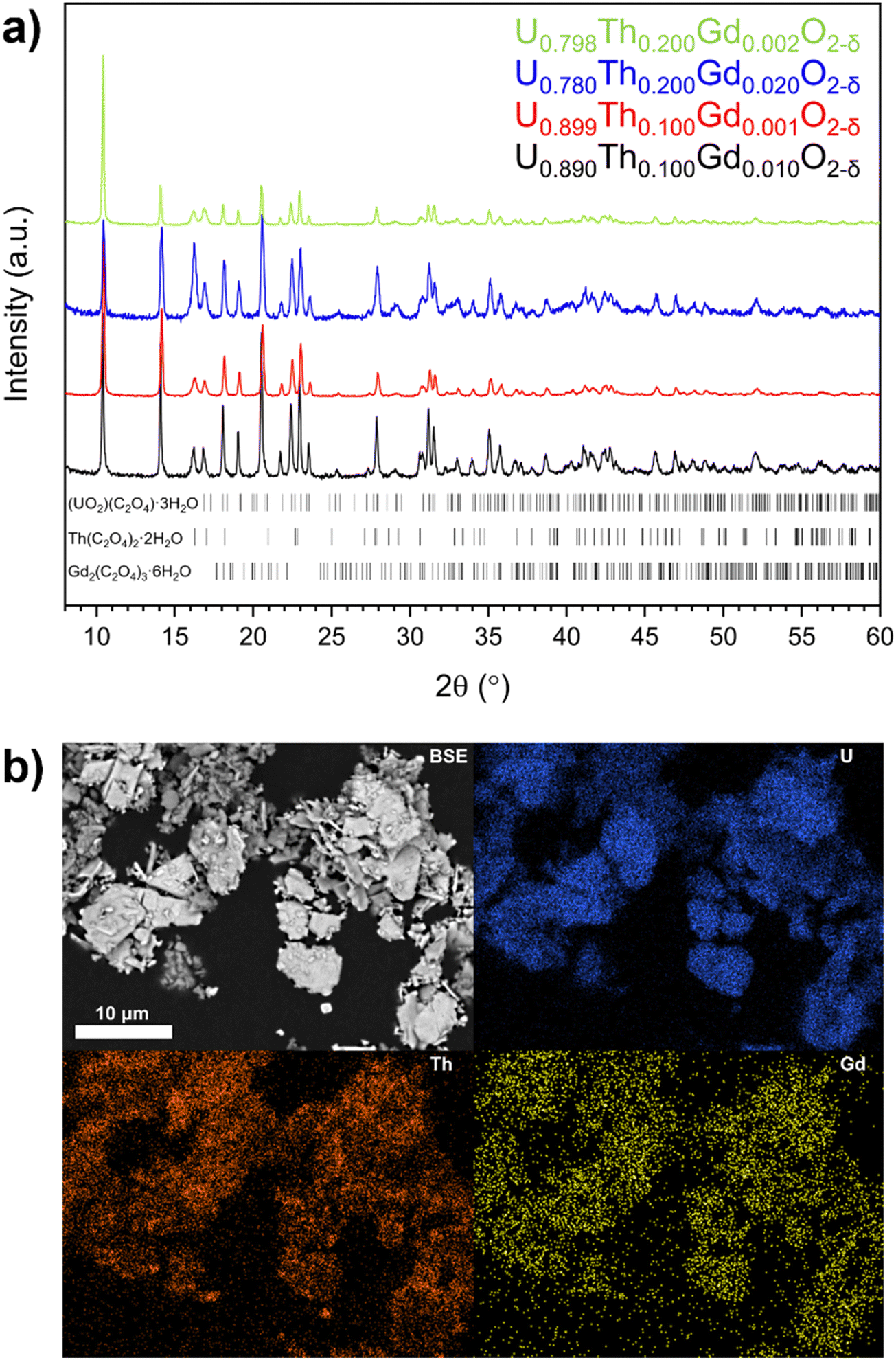 | ||
| Fig. 1 (a) XRD data for synthesised oxalate powders, highlighting reflections indexed to oxalates of U (ICSD card no. #172778), Th (ICSD card no. #248038) and Gd (ICSD card no. #121695). (b) BSE micrograph and EDS element distribution maps of the oxalate precursor for the nominal U0.798Th0.200Gd0.002O2−δ composition. | ||
Complete decomposition to the base oxides occurred by ∼600 °C as shown by thermogravimetric (TG) and differential thermal analysis (DA) (Fig. 2a). Two major mass losses at temperatures of <320 °C (T1 and T2), corresponding to water loss as the oxalates were dehydrated (Fig. 2a) were observed, and a mass loss at 320 °C (T3) was attributed to CO2 evolution during decomposition of the oxalate (Fig. S2, ESI†). Each of these phenomena exhibited additional features; for example, at T1 and T2, there are two features, and T3 exhibits three (Fig. 2a). This supports the presence of separate oxalates of U, Th and Gd, although it does not rule out the presence of at least a portion of mixed oxalate. No further mass losses were measured upon heating beyond 600 °C. Two endothermic transformations were assigned to water loss between 90 °C and 320 °C, while exothermic reactions corresponding to CO2 and CO evolution occurred between 330 °C and 420 °C, in agreement with the TG data.
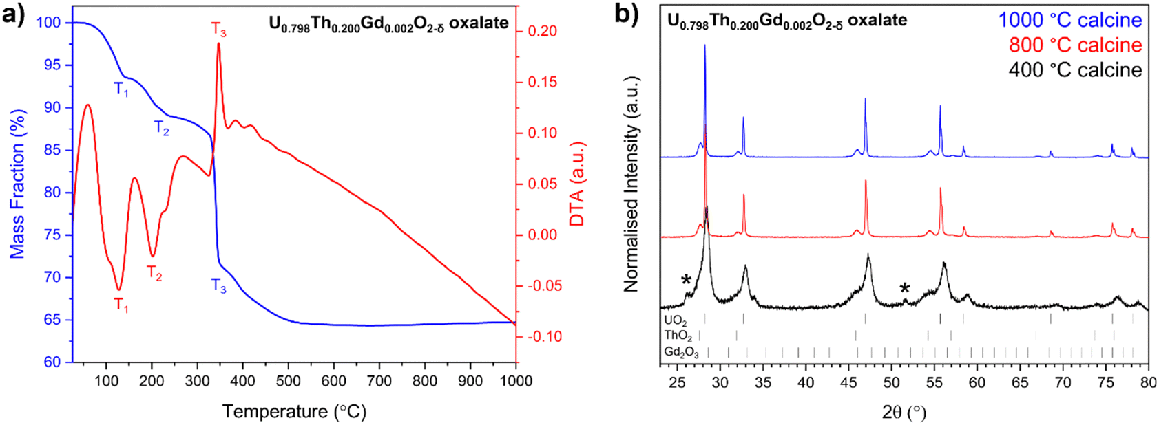 | ||
| Fig. 2 (a) Thermal analysis of the oxalate powder prepared to form U0.798Th0.200Gd0.002O2−δ co-precipitated pellets and; (b) XRD data collected on U0.798Th0.200Gd0.002O2−δ oxide powders decomposed from oxalates at 400 °C, 800 °C and 1000 °C. Two sets of fluorite peaks are indexed to UO2 (ICSD card no. #160814) and ThO2 (ICSD card no. #253564). Additional peaks denoted with ‘*’ in the 400 °C trace correspond with residual oxalate content, indicating incomplete decomposition. Cubic C-type Gd2O3 (ICSD card no. #94892) peaks were absent in all traces. | ||
Oxide powders produced by the thermal decomposition of the nominal U0.798Th0.200Gd0.002O2−δ material at 400 °C, 800 °C and 1000 °C were analysed by XRD (Fig. 2b). The peak broadening observed in the oxide calcined at 400 °C, when compared with the materials calcined at higher temperature, indicates a significantly smaller crystallite size. Reflections relating to oxalate were not observed in either the 800 °C or 1000 °C calcined oxides, suggesting successful decomposition to oxide at these temperatures, in accordance with corresponding TG data on the same material. Gd2O3 was not observed in any of the calcined powders, suggesting complete incorporation within a solid solution with at least one of the other constituents, or that it was present at concentrations below the detection limit of the XRD. The optimum calcination temperature for all oxalates was selected to be 800 °C, as this was evidenced to fully decompose each compound into oxides. The decomposition of the oxalate into distinct ThO2 and UO2 phases was observed for all targeted compositions, supporting the hypothesis that more than one oxalate was formed during the precipitation from solution (Fig. S3, ESI†).
3.2 Characterisation of sintered disposal-MOX
:Gd ratio of 100:1 at a 5 g scale requires a Gd2O3 mass of 0.0039 g. Quantitative EPMA point spectra collected on sintered pellets provided comparison with the bulk analysis provided by the total acid digest method (Table 1). Both methods were in good agreement with one another, despite differences induced by the nature of the measurements (EPMA samples individual points in a heterogenous matrix, while ICP-MS measures the composition of a completely dissolved material), and confirmed that materials prepared by the solid state route achieved compositions closer to those targeted than the co-precipitated samples, and that Th and Gd concentrations were in excess of desired stoichiometries in all co-precipitated samples.
m space group (Fig. 3). The lack of additional ThO2 or Gd2O3 reflections indicated complete incorporation of both Th4+ and Gd3+ cations into solid solution within the UO2 matrix.
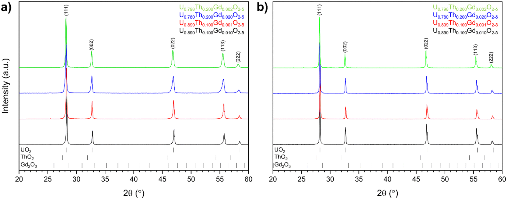 | ||
| Fig. 3 X-ray diffraction analysis for disposal-MOX materials produced by (a) solid state and; (b) co-precipitation routes. | ||
Corresponding Rietveld analysis (Table 2) revealed that Th4+ substitution, irrespective of synthesis route, resulted in an increase in the unit cell parameter a (Å) relative to the host UO2 matrix, consistent with the relative size of Th4+ and U4+ in 8-fold coordination (1.19 Å and 1.14 Å, respectively). Whilst Gd3+ is slightly larger (1.193 Å), it is known to have the opposite effect on the lattice parameter of UO2 due to the lattice contraction resulting from the generation of oxygen vacancies (VO) or U5+ (radius 0.89 Å) in the charge compensation required for the incorporation of a trivalent species on a tetravalent site.31–33 The addition of Gd3+ was shown to result in a decrease in the lattice parameter in sintered materials, particularly for the materials prepared by the solid state route.
| Synthesis route | Composition | a (Å) | R wp (%) | χ 2 |
|---|---|---|---|---|
| Co-prec. | U0.848(7)Th0.146(7)Gd0.006(2)O2−δ | 5.49134(8) | 10.495 | 1.566 |
| Co-prec. | U0.835(5)Th0.131(3)Gd0.034(2)O2−δ | 5.48806(5) | 10.000 | 1.724 |
| Co-prec. | U0.758(1)Th0.234(9)Gd0.008(0)O2−δ | 5.50454(6) | 11.331 | 2.085 |
| Co-prec. | U0.666(6)Th0.266(4)Gd0.069(2)O2−δ | 5.50871(5) | 9.832 | 1.723 |
| Solid state | U0.889(3)Th0.106(3)Gd0.005(1)O2−δ | 5.48019(1) | 14.465 | 2.343 |
| Solid state | U0.866(3)Th0.105(2)Gd0.029(2)O2−δ | 5.47731(1) | 16.764 | 2.609 |
| Solid state | U0.801(4)Th0.192(4)Gd0.008(7)O2−δ | 5.49585(1) | 11.284 | 1.721 |
| Solid state | U0.759(4)Th0.187(4)Gd0.054(2)O2−δ | 5.49042(2) | 16.086 | 2.576 |
In accordance with the XRD data, lattice disorder relative to pure UO2 was indicated by a broadening and shift in the Raman in T2g mode at 445 cm−1 (Fig. 4), which is characteristic of the fluorite structure, to higher wavenumbers.31,34 The magnitude of the shift varied linearly with total Th4+ and Gd3+ additions (Table S1, ESI†). The Raman spectra exhibited a broad set of overlapping bands at 575 cm−1, referred to as the defect region, which can be deconvoluted to reveal individual contributions from three distinct defect bands: U1, U2 and U3. The U1 band, which typically occurs around 540 cm−1, results from lattice distortion due to VO.31–35 The intensity of the U1 band, measured by its full width half maximum (FWHM), was found to increase with increasing Gd3+ content (Fig. S5, ESI†), suggesting that Gd3+ incorporation into the UO2 lattice was charge compensated via VO generation regardless of compositions or fabrication route. The U2 band, also known as the resonant first-order longitudinal optical (1LO) mode, is activated as the perfect fluorite symmetry is broken. This band was the most intense in samples with greatest Th4+ and Gd3+ content, a result of increased disorder due to incorporation of these differently sized cations within the UO2 lattice, and from VO generation.34 The U3 band can be assigned to cuboctahedral symmetry, which results from oxygen interstitials forming a hyper-stoichiometric U4O9 structure. The low intensity of this band in all spectra confirms the absence of highly oxidised clusters. The full suite of Raman data for all samples is given in Fig. S4 (ESI†).
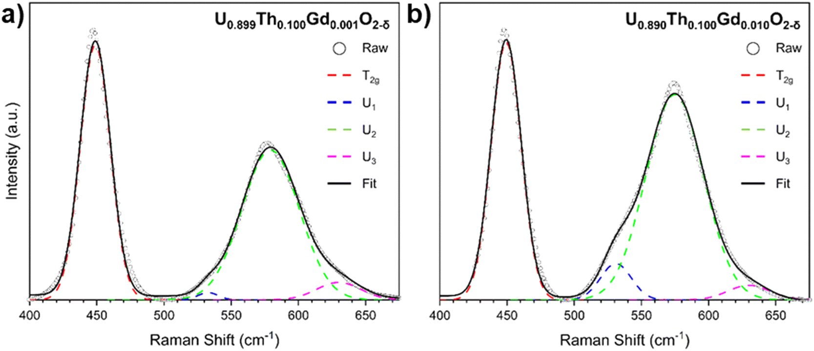 | ||
| Fig. 4 Deconvoluted Raman spectra for coprecipitated materials targeting nominal compositions (a) U0.899Th0.100Gd0.001O2−δ and (b) U0.890Th0.100Gd0.010O2−δ. | ||
To determine whether a portion of the U in disposal-MOX was oxidised to U5+ to charge compensate for the incorporation of Gd3+, U M4-edge HERFD-XANES spectra were collected on sintered pellets of each composition. The obtained spectra were normalised and fit using linear combination fitting (LCF) and verified with iterative transformation factor analysis (ITFA), as presented in Fig. 5. When comparing the spectral features to the known KU5+O3 reference compound, it was apparent that no U5+ was present in any of the targeted compositions (Fig. 5a).36,37 For the samples prepared by the co-precipitated route, a shoulder was present on the high energy side of the peak representative of U4+, which was not present for the solid state materials; this could be attributed to disorder within the UO2 lattice,38,39 in agreement with the XRD and Raman spectroscopy data. These results strongly indicate that VO generation, not oxidation to U5+, is the dominant charge compensation mechanism for all the obtained disposal-MOX samples.
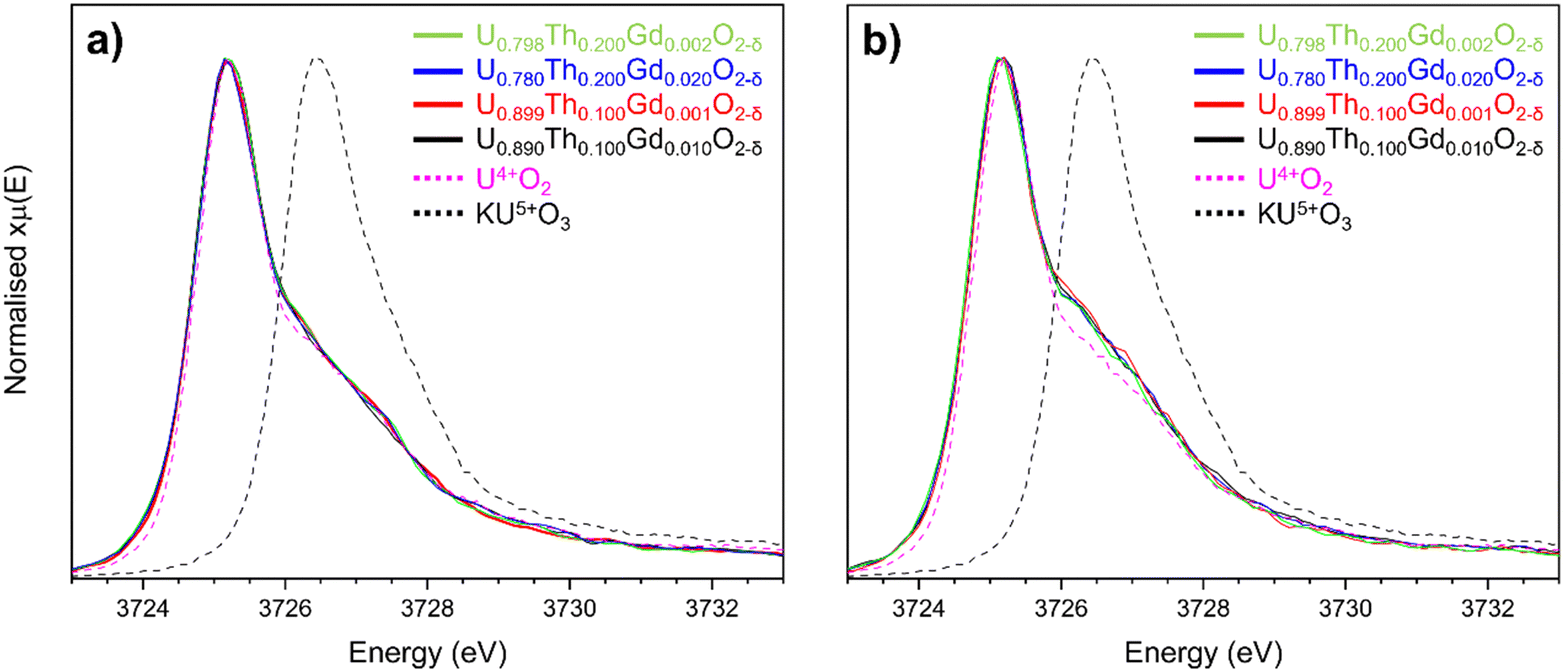 | ||
| Fig. 5 Comparison of U M4-edge HERFD-XANES spectra collected on (a) solid state and (b) co-precipitated disposal-MOX samples alongside representative U4+ and U5+ reference compounds. | ||
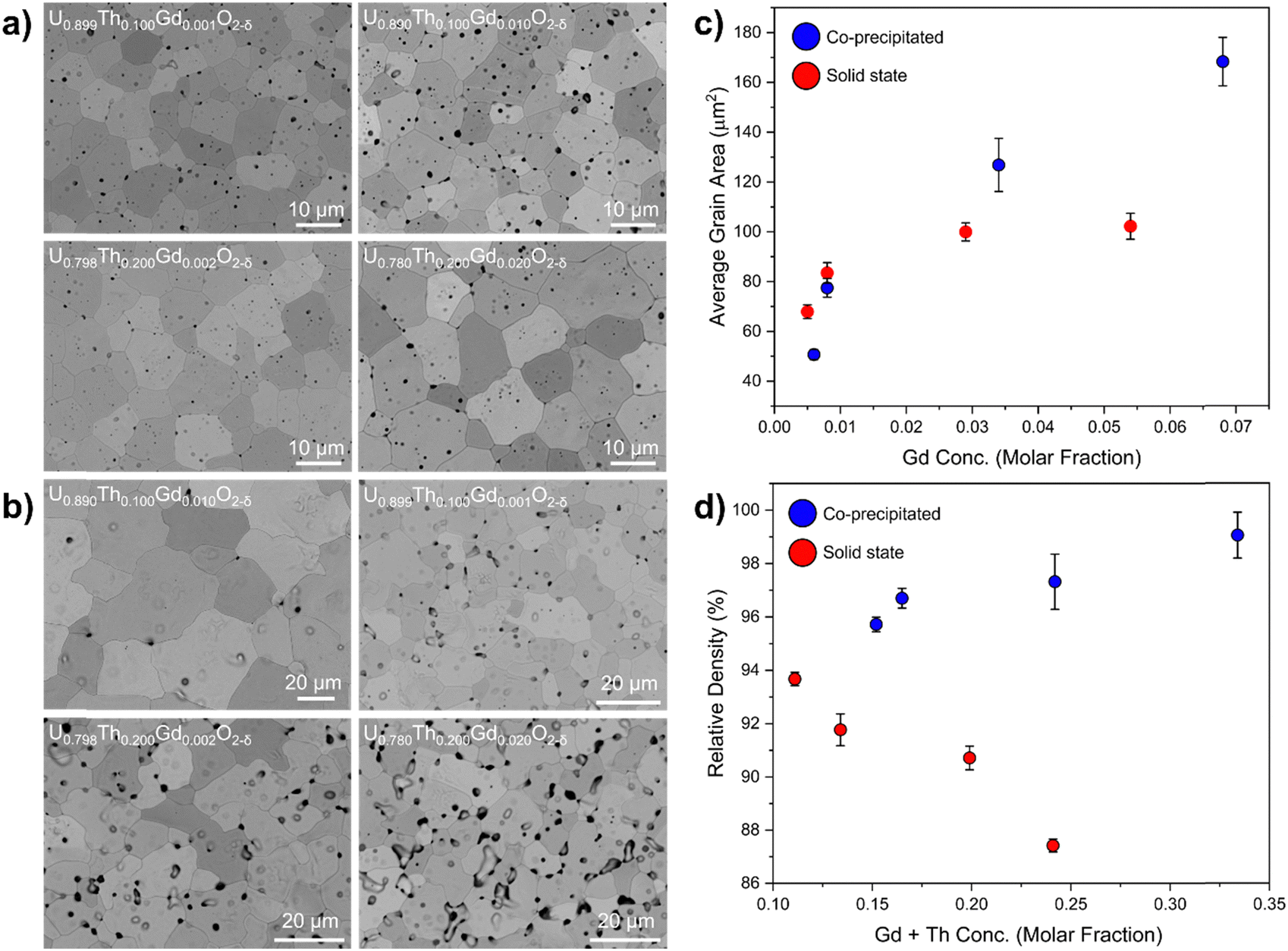 | ||
| Fig. 6 Microstructure and density analysis of disposal-MOX materials. Showing (a) BSE images of co-precipitated pellets; (b) BSE images of pellets prepared by the solid state route; (c) plot of average grain size as a function of the molar fraction of Gd; and (d) the relative density as a function of the molar fraction of Th and Gd. Relative density was calculated by dividing the measured density by the theoretical density. Theoretical density was calculated using refined lattice parameters and compositions measured by ICP-OES. | ||
When compared with co-precipitated materials, the materials prepared by the solid state route showed signs of poor sinterability, with an unusual morphology, variance in grain size and more extensive intergranular porosity. Lower rates of diffusion during the sintering of the solid state samples evidenced poor homogenisation and lower reactive surface area of the milled oxides compared to those produced via wet co-precipitation. It is possible that the Gd is already dissolved in UO2 in materials prepared by the co-precipitation route, enhancing diffusion relative to the solid state route materials, in which Gd is not as intimately mixed. In both co-precipitated and solid state samples, the grain size was observed to increase with increasing Gd concentration (Fig. 6c). The relative density of the co-precipitated samples increased gradually with increasing Th and Gd content, correlating well with the measured grain size increase; however, in the pellets prepared by the solid state route, the opposite trend was observed. This is likely correlated with the increased intergranular porosity in compositions containing a greater amount of Th4+.
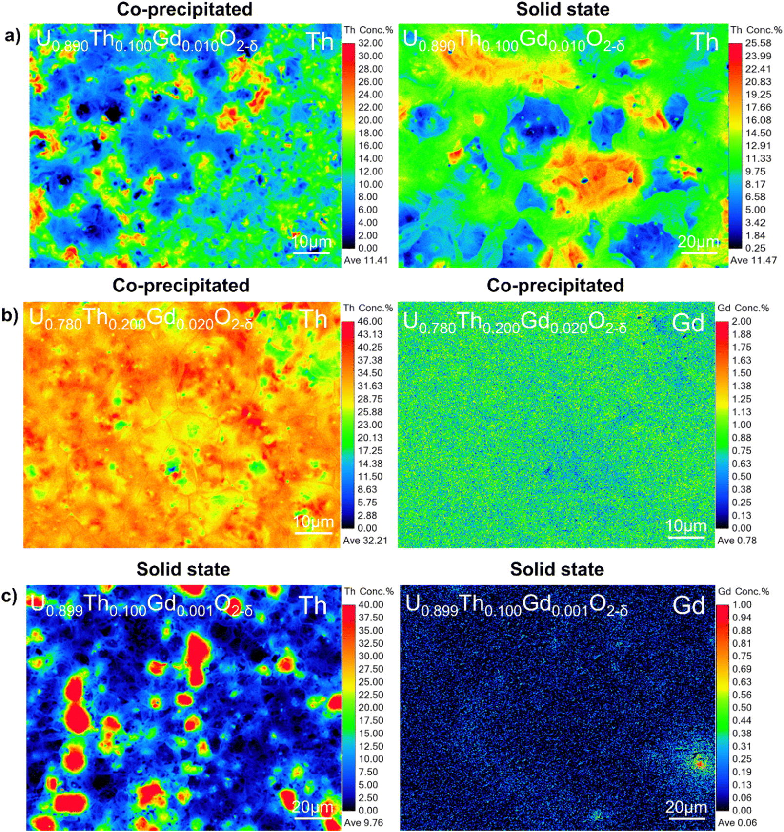 | ||
| Fig. 7 Elemental distribution of Th4+ and Gd3+ in disposal-MOX samples. Showing EMPA maps of (a) comparable compositions prepared by co-precipitation and solid state routes (note the different scale); (b) co-precipitated pellets revealing homogeneity of Th and Gd distribution; and (c) solid state pellets revealing lack of correlation between areas of elevated Th4+ and Gd3+ content. | ||
Although the co-precipitated materials were more homogeneous, they also exhibited areas that contained both Th and Gd, at concentrations of approximately 30–40 at% and >1 at%, respectively (Fig. 7a and b). Regions of elevated Th4+ did not typically correlate with Gd-rich regions in the solid state samples (Fig. 7c), confirming that this behaviour was dependent on fabrication route. This may be important when considering the necessity of Gd, a neutron absorber, to be in close proximity to Pu to provide a robust control on criticality.
4. Conclusions
Two synthesis routes for the fabrication of a conceptual disposal-MOX wasteform for the immobilisation of separated Pu inventories were demonstrated. Single phase cubic fluorite materials were obtained for all compositions produced using both oxalic co-precipitation and solid state synthesis routes – the latter mimicking the MIMAS MOX fuel synthesis route – as confirmed by XRD. The incorporation of Th4+, as a structural surrogate for Pu4+ in UO2, was evidenced through an expansion of the fluorite lattice, whereas Gd3+ additions contracted the lattice due to VO generation in a charge compensation mechanism, evidenced by deconvolution of Raman spectroscopy. Materials prepared via the solid state route successfully reproduced the MIMAS MOX-fuel microstructure, although further milling optimisation studies are warranted. The application of U M4 HERFD-XANES indicated that U5+ was not stabilised in appreciable concentrations in materials produced by either synthesis route. The main difference between the two synthesis routes was not in the chemistry, but in the distribution of Th4+ and Gd3+ as well as the overall microstructure, which was more heterogeneous in materials prepared by the solid state route method. Although single phase disposal-MOX could feasibly be produced by either synthesis route, the adaptability of the MIMAS process to produce (U,Pu,Gd)O2 pellets at an industrial scale is clearly more compatible with a PuO2 feedstock. These data set a benchmark for further disposal-MOX studies, in an effort to underpin its suitability for geological disposal, including industrial fabrication, aqueous durability, radiation damage tolerance and mechanical properties.Data availability
The data that support the findings of this study are available from the corresponding author, upon reasonable request.Conflicts of interest
There are no conflicts to declare.Acknowledgements
This research utilised the National Nuclear User Facilities HADES45 and PLEIADES, established with financial support from the UK Engineering and Physical Science Research Council (EPSRC) and BEIS (EP/T011424/1, EP/V035215/1). CLC is grateful to EPSRC for the award of an ECR Fellowship (EP/N017374/1) and for funding under the TRANSCEND consortium (EP/S01019X/1). LRB wishes to thank the Royal Academy of Engineering for funding through the Research Fellowship scheme. We gratefully acknowledge Stuart Creasey-Gray for assistance in collecting the EPMA data. We acknowledge the European Synchrotron Radiation Facility for provision of synchrotron radiation facilities (under proposal number MA-4821) and we would like to thank Tatiana Poliakova, Anastasiia Smirnova and Jurij Galanzew for assistance in using the Rossendorf beamline (ROBL, BM20) remotely during the pandemic. Sarah Pepper, Ritesh Mohun, Josh Radford and Hannah Smith are gratefully acknowledged for their assistance with data collection, and we wish to thank Paul Cook and Paul Heath from, respectively, the Nuclear Decommissioning Authority and Nuclear Waste Services, for insightful discussions regarding the data and the context of the work.References
- Nuclear Decommissioning Authority, “Progress on Plutonium Consolidation, Storage and Disposition,” 2019.
- N. C. Hyatt, Energy Policy, 2017, 101, 303–309 CrossRef.
- N. C. Hyatt, npj Mater. Degrad., 2020, 4, 28 CrossRef CAS.
- A. M. MacFarlane, F. von Hippel, J. Kang and R. Nelson, Bull. At. Sci., 2001, 57, 53–57 CrossRef.
- J. Kang, F. N. von Hippel, A. MacFarlane and R. Nelson, Sci. Global Security, 2002, 10(2), 85–101 CrossRef.
- A. M. Macfarlane, Prog. Nucl. Energy, 2007, 49(8), 644–650 CrossRef CAS.
- G. Lumpkin, Elements, 2006, 2, 365–372 CrossRef CAS.
- S. M. Thornber, M. C. Stennett, E. R. Vance, D. T. Chavara, I. Watson, M. Jovanovic, J. Davis, D. Gregg and N. C. Hyatt, MRS Adv., 2018, 3, 1065–1071 CrossRef CAS.
- D. J. Gregg, R. Farzana, P. Dayal, R. Holmes and G. Triani, J. Am. Ceram. Soc., 2020, 103, 5424–5441 CrossRef CAS.
- L. R. Blackburn and N. C. Hyatt, Enc. Nucl. Energy, 2021, pp. 650–662 Search PubMed.
- R. Böhler, M. J. Welland, D. Prieur, P. Cakir, T. Vitova, T. Preussmann, I. Pidchenko, C. Hennig, C. Gueneau, R. J. M. Konings and D. Manara, J. Nucl. Mater., 2014, 448, 330–339 CrossRef.
- M. Durazzo, F. B. V. Oliveira, E. F. Urano De Carvalho and H. G. Riella, J. Nucl. Mater., 2010, 400, 183–188 CrossRef CAS.
- F. Garrido, S. Moll, G. Sattonnay, L. Thomé and L. Vincent, Nucl. Instrum. Methods Phys. Res., Sect. B, 2009, 267, 1451–1455 CrossRef CAS.
- T. Wiss, J.-P. Hiernaut, D. Roudil, J.-Y. Colle, E. Maugeri, Z. Talip, A. Janssen, V. Rondinella, R. J. M. Konings, H.-J. Matzke and W. J. Weber, J. Nucl. Mater., 2014, 451, 198–206 CrossRef CAS.
- D. W. Shoesmith, J. Nucl. Mater., 2000, 282, 1–31 CrossRef CAS.
- A. Leenaers, L. Sannen, S. Van den Berghe and M. Verwerft, J. Nucl. Mater., 2003, 317, 226–233 CrossRef CAS.
- A. Casella, B. Hanson and W. Miller, J. Nucl. Mater., 2016, 476, 45–55 CrossRef CAS.
- M. Razdan and D. W. Shoesmith, J. Electrochem. Soc., 2014, 161, H105–H113 CrossRef CAS.
- Z. Talip, S. Peuget, M. Magnin, M. Tribet, C. Valot, R. Vauchy and C. Jegou, J. Nucl. Mater., 2018, 499, 88–97 CrossRef CAS.
- P. A. Bingham, R. J. Hand, M. C. Stennett, N. C. Hyatt and M. T. Harrison, Mater. Res. Soc. Symp. Proc., 2008, 1107, 421–428 CrossRef.
- H. Bariot, J. Van Vliet, G. Chiarelli, J. Edwards, S. H. Nagai and F. Reshnetnikov, International Atomic Energy Agency, 2000, IAEA-SM-358/VII link.
- D. Warin, M. Bauer, M. Seiss and R. Lorenzelli, International Atomic Energy Agency, 1997, IAEA-TECDOC-941 link.
- D. Legland, I. Arganda-Carreras and P. Andrey, Bioinformatics, 2016, 32, 3532–3534 CrossRef CAS PubMed.
- J. Schindelin, et al. , Nat. Methods, 2012, 9, 676–682 CrossRef CAS.
- A. C. Scheinost, J. Claussner, J. Exner, M. Feig, S. Findeisne, C. Hennig, K. O. Kvashnina, D. Naudet, D. Prieur, A. Rossberg, M. Schmidt, C. Qiu, P. Colomp, C. Cohen, E. Dettona, V. Dyadkin and T. Stumpf, J. Synchrotron Radiat., 2021, 28, 333–349 CrossRef CAS PubMed.
- K. O. Kvashnina and A. C. Scheinost, J. Synchrotron Radiat., 2016, 23, 836–841 CrossRef CAS.
- B. Ravel and M. Newville, J. Synchrotron Radiat., 2005, 12, 537–541 CrossRef CAS.
- A. Rossberg, K. U. Ulrich, S. Weiss, S. Tsushima, T. Hiemstra and A. C. Scheinost, Environ. Sci. Technol., 2009, 43, 1400–1406 CrossRef CAS.
- V. Tyrpekl, J. F. Vigier, D. Manara, T. Wiss, O. Dieste Blanco and J. Somers, J. Nucl. Mater., 2015, 460, 200–208 CrossRef CAS.
- Y. J. Shin, I. S. Kim, W. K. Lee, H. S. Shin and S. G. Ro, J. Radioanal. Nucl. Chem., 1996, 209, 217–223 CrossRef CAS.
- S. Karcher, R. Mohun, T. Olds, M. Weber, K. Kriegsman, X. Zhao, X. Guo, C. Corkhill, D. Field and J. McCloy, J. Raman Spectrosc., 2022, 53, 988–1002 CrossRef CAS.
- H. Smith, L. T. Townsend, R. Mohun, T. Cordara, M. C. Stennett, J. F. W. Mosselmans, K. O. Kvashnina and C. L. Corkhill, Chem. Commun., 2022, 5, 163 CrossRef CAS.
- H. Smith, L. T. Townsend, R. Mohun, J. F. W. Mosselmans, K. Kvashnina, N. C. Hyatt and C. L. Corkhill, Sci. Rep., 2024, 14, 1656 CrossRef CAS.
- G. Guimbretière, L. Desgranges, A. Canizares, G. Carlot, R. Caraballo, C. Jegou, F. Duavl, N. Raimbous, M. R. Ammar and P. Simon, Appl. Phys. Lett., 2012, 100, 251914 CrossRef.
- J. Lee, J. Kim., Y.-S. Youn, N. Liu, J.-G. Kim, Y.-K. Ha, D. W. Shoesmith and J.-Y. Sun, J. Nucl. Mater., 2017, 486, 216–221 CrossRef CAS.
- K. O. Kvashnina, S. M. Butorin, P. Martin and P. Glatzel, Phys. Rev. Lett., 2013, 111, 253002 CrossRef CAS.
- K. O. Kvashnina and S. M. Butorin, Chem. Commun., 2022, 58, 327 RSC.
- D. Prieur, L. Martel, J.-F. Vigier, A. C. Scheinost, K. O. Kvashnina, J. Somers and P. M. Martin, Inorg. Chem., 2018, 57, 1535–1544 CrossRef CAS PubMed.
- E. Gerber, A. Y. Romanchuk, S. Weiss, S. Bauters, B. Schacherl, T. Vitova, R. Hubner, S. S. A. Azzam, D. Detollenaere, D. Banerjee, S. M. Butorin, S. N. Kalmykov and K. O. Kvashnina, Inorg. Chem. Front., 2021, 8, 1102–1110 RSC.
- R. W. Harrison, J. Morgan, J. Buckley, T. Abram, D. T. Goddard and N. J. Barron, J. Nucl. Mater., 2021, 557, 153302 CrossRef CAS.
- Y. Cherkaski, N. Clavier, L. Brissonneau, R. Podor and N. Dacheux, J. Eur. Ceram. Soc., 2017, 37, 3381–3391 CrossRef CAS.
- N. Hingant, N. Clavier, N. Dacheux, S. Hubert, N. Barre, R. Podor and L. Aranda, Powder Technol., 2011, 208, 454–460 CrossRef CAS.
- D. Horlait, F. Lebreton, A. Gauthe, M. Caisso, B. Arab-Chapelet, S. Picart and T. Delahaye, J. Nucl. Mater., 2014, 444, 181–185 CrossRef CAS.
- J. Noirot, L. Desgranges and J. Lamontagne, J. Nucl. Mater., 2008, 372, 318–339 CrossRef CAS.
- N. C. Hyatt, C. L. Corkhill, M. C. Stennett, R. J. Hand, L. J. Gardner and C. L. Thorpe, IOP Conf. Ser.: Mater. Sci. Eng., 2020, 818, 012022 CAS.
Footnote |
| † Electronic supplementary information (ESI) available. See DOI: https://doi.org/10.1039/d4ma00420e |
| This journal is © The Royal Society of Chemistry 2024 |