
 Open Access Article
 This Open Access Article is licensed under a
 Creative Commons Attribution 3.0 Unported Licence
High-temperature ternary Cu–Si–Al alloy as a core–shell microencapsulated phase change material: fabrication via dry synthesis method and its thermal stability mechanism†
Masahiro
Aoki
a,
Melbert
Jeem
 b,
Yuto
Shimizu
c,
Takahiro
Kawaguchi
c,
Minako
Kondo
b,
Tomokazu
Nakamura
b,
Chihiro
Fushimi
d and
Takahiro
Nomura
*b
b,
Yuto
Shimizu
c,
Takahiro
Kawaguchi
c,
Minako
Kondo
b,
Tomokazu
Nakamura
b,
Chihiro
Fushimi
d and
Takahiro
Nomura
*b
aGraduate School of Bio-Applications and Systems Engineering, Tokyo University of Agriculture and Technology, 2-24-16, Naka-cho, Koganei, Tokyo, 184-8588, Japan
bFaculty of Engineering, Hokkaido University, Kita 13 Nishi 8, Kita-ku, Sapporo, 060-8628, Japan. E-mail: nms-tropy@eng.hokudai.ac.jp; Fax: +81 11 706 6849; Tel: +81 11 706 6842
cGraduate School of Engineering, Hokkaido University, Kita 13 Nishi 8, Kita-ku, Sapporo, 060-8628, Japan
dDepartment of Chemical Engineering, Tokyo University of Agriculture and Technology, 2-24-16, Naka-cho, Koganei, Tokyo 184-8588, Japan
First published on 13th December 2023
Abstract
In the quest for efficient high-temperature thermal energy storage systems (TES) and power-to-heat-to-power systems (PHP), this study focuses on the development of Cu–12.8Si–20Al/Al2O3 core–shell microencapsulated phase change materials (MEPCMs). The Cu–12.8Si–20Al alloy, with melting point range of 738–758 °C was selected as the core PCM. Two subsequent physical methods were performed to optimize the MEPCMs: (1) uniformly coating the core with shell nanoparticles via a dry synthesis mechanical impact technique; (2) conducting heat oxidation in an O2 atmosphere to foster a robust shell structure. To ascertain the optimal structure for the MEPCM, we investigated three shell variants: α-Al2O3, AlOOH, and a mixture of both. Significantly, the α-Al2O3 nanoparticles manifested a dual-layered shell, defined by an internally sintered α-Al2O3 nanoparticles layer and an overlying sub-nanoparticles layer. This construction enhanced the MEPCMs’ thermal resilience: allowing them to withstand over 600 cycles of endothermic and exothermic phases, as well as affirming their endurance under extensive 100 h air exposure at 900 °C. The synergy between α-Al2O3 and AlOOH in the mixed shell revealed a pivotal role of AlOOH, which served as an adept sintering agent to enhance the MEPCM's thermal stability. In conclusion, the Cu–Si–Al/Al2O3 MEPCM was successfully produced as a promising candidate in high-temperature latent heat storage applications.
Introduction
The production capacity of variable renewable energy (VRE), such as wind and concentrated solar power (CSP), continues to grow each year due to the reduction in equipment costs.1,2 However, VRE presents challenges in flexibly meeting power demands. Power demand must align with the amount of power supplied for a stable power supply. As such, power-to-heat-to-power (PHP) systems that store energy in inexpensive thermal energy storage (TES) materials and release it according to energy demand are attracting attention.3–6 TES materials and the heat storage temperature in a PHP system are determined by the operating temperature of its heat cycle with which it will be integrated. From the perspective of the Carnot efficiency, a higher operating temperature is desirable. Therefore, high-temperature TES has recently become necessary, with proposals like the Brayton cycle for CSP operating at over 700 °C.7 Presently, sensible heat storage (SHS) materials, one of the TES materials, are utilized due to their low cost.8,9 However, SHS materials have a low energy storage density of 25 kW m−3,3 leading to problems such as the need for large-scale storage facilities and corresponding limitations in their application.Latent heat storage (LHS) materials, which store latent heat accompanying phase changes of materials, are attracting attention due to their high energy storage density.3 Molten salts and alloy series materials that undergo a phase change in the high temperature range have been researched.10 Molten salts are economical (≥110 US$ per tonne),11 which has led to extensive material development12 and application research.13 However, the low thermal conductivity14 and the associated inflexibility have been problematic. On the other hand, alloy-based LHS materials, having high thermal conductivity, high latent heat capacity, and stability against heat, are gaining attention.15 For instance, the thermal conductivities of representative high-temperature LHS materials aluminum (melting point: 660–661 °C) and copper (melting point: 1077–1083 °C) are 204 W m−1 K−1 and 350 W m−1 K−1, respectively.15 Rea et al. have successfully demonstrated a prototype TES system using Al–Si LHS materials.16 However, alloy-based LHS materials have a high corrosiveness,10 leading to challenges such as storage container damage, leakage, and safety concerns. Moreover, LHS materials transitioning between liquid and solid phases posed issues in handling.
Microencapsulated phase change materials (MEPCMs), a type of anti-corrosive packing,10 is considered promising due to benefits like increased heat transfer surface area of the PCM and reduced volume change associated with phase transition.17,18 The MEPCMs are expected to prevent corrosion and improve PCM manageability. MEPCM production methods are classified into physical, physic-chemical, and chemical.19 For high-temperature MEPCMs, physio-chemical methods are primarily utilized. Previous research has proposed several methods for preparing high-temperature MEPCMs, including sol–gel20,21 and sacrificial layers.22 Our research group has developed a highly durable, high-temperature MEPCMs using two-steps: (1) creating an AlOOH precursor layer on PCM microspheres using hydroxide precipitation in hot water and (2) a subsequent heat-oxidation treatment to yield a stable Al2O3 shell.23,24 These hydrolysis and heat oxidation methods were also applied to develop Al–10mass%Zn MEPCMs (melting point: 640 °C).25 However, MEPCMs employing Cu-based alloy PCMs with melting points exceeding 700 °C have not been developed.
While the need for cost-effective and straightforward fabrication of MEPCMs is evident, conventional high-temperature fabrication methods, like the sol–gel approach, come with challenges. These often demand reaction control and safety management due to wet processes, which are replete with complex chemical reactions. Consequently, there has been significant interest in encapsulation method that avoids the complexities of these chemical reactions.26,27 Among these, spray drying, which involves spraying shell material containing solvent onto the PCM surface, has gained traction.28 However, it has limitations for high-temperature MEPCMs (above 500 °C) because of restrictions in shell material types.26 Furthermore, several physical methods grapple with issues such as incomplete coating of the PCM particle surface, potential leaks, degradation in performance, and diminished mechanical strength.26
Given these challenges, our study takes a novel turn, introducing a Cu-based MEPCM fabricated through the combination of high-speed impact blending (HIB) and a subsequent heat oxidation treatment. The principles of HIB method are rooted in the dynamics of mechanical impact processes.29 It prepares complexes of both organic and inorganic materials without relying on solvents. This method, involving dry and impact blending, depends on the dynamic interactions between particles. These interactions achieve a balance between adhesion – where particles stick; and abrasion – where particles might be worn down or refined. Although HIB method has been used in electrode particle coating30,31 and particle modifications,32,33 its utilization in the fabrication of MEPCMs remains underexplored. Notably, there is no existing documentation on MEPCMs creation using HIB, and the mechanisms for surface coating by HIB are not fully understood. For our Cu-based alloy MEPCM, we devised a twofold fabrication process: (1) HIB treatment to achieve a uniform coat on the PCM surfaces with shell nanoparticles (NPs), either AlOOH or α-Al2O3, and (2) a heat-oxidation process to sinter these shell NPs, forming a stable α-Al2O3 shell. This dry synthesis method, which combines HIB and heat oxidation treatment, not only offers an alternative to the pitfalls of wet processes but also sets the stage for scalable and economical solutions. The fundamental physics behind this approach grants the adaptability to alter the MEPCM shell structure by modifying the composition of the shell NPs. Additionally, by optimizing the PCM composition, the method holds promise for MEPCMs suitable for a wide temperature spectrum, from the lower to the upper extremes.
Experimental
Preparation of the MEPCMs
Microspherical particles of Cu–12.8mass%Si–20mass%Al (Cu–12.8Si–20Al) alloy, prepared through spinning disk atomization (Hikari Material Industry Co. Ltd), were used as the PCM raw material. The raw material's diameter, melting temperature, and LH were 20–45 μm, 738–758 °C (Fig. 2a and Fig. S1, ESI†), and 254 J g−1, respectively. AlOOH NPs powder was purchased from TAIMEI Chemicals Co., Ltd (type: C06, 50%, diameter: 0.7 μm). α-Al2O3 NPs powder was purchased from Kojundo Chemical Laboratory Co. Ltd (purity: 99.99%, diameter: 0.3 μm).
Fig. 1 illustrates a schematic diagram of MEPCM preparation using a hybridization system. Core particles (Cu–12.8Si–20Al) were mixed with shell NPs (α-Al2O3 and AlOOH) in an 8![[thin space (1/6-em)]](https://www.rsc.org/images/entities/char_2009.gif) :2 volume ratio using a ball mill (140 rpm, 10 min). The resulting mixture (30 g) underwent a HIB treatment (rotation speed: 50 m s−1, processing time: 3 min, atmosphere: Ar) to attach the shell NPs onto the core PCM surfaces by using a HIB machine (Model: NHS-0, Nara Machinery Co. Ltd, Japan). The HIB process was carried out in five batches for each parameter set, with the fifth batch as the sample (hybridized-PCM). Subsequently, the hybridized-PCMs were subjected to heat oxidation treatment in an oxygen atmosphere (99.5% purity, flowing at 200 mL min−1). The temperature was ramped from room temperature to 1000 °C at a rate of 10 °C min−1 and sustained at 1000 °C for three hours. Table 1 summarizes the naming of the MEPCMs pre and post heat oxidation. The HIB treatment PCM is named hybridized PCM. The PCM encapsulated by subsequent heat oxidation treatment is named MEPCM.
:2 volume ratio using a ball mill (140 rpm, 10 min). The resulting mixture (30 g) underwent a HIB treatment (rotation speed: 50 m s−1, processing time: 3 min, atmosphere: Ar) to attach the shell NPs onto the core PCM surfaces by using a HIB machine (Model: NHS-0, Nara Machinery Co. Ltd, Japan). The HIB process was carried out in five batches for each parameter set, with the fifth batch as the sample (hybridized-PCM). Subsequently, the hybridized-PCMs were subjected to heat oxidation treatment in an oxygen atmosphere (99.5% purity, flowing at 200 mL min−1). The temperature was ramped from room temperature to 1000 °C at a rate of 10 °C min−1 and sustained at 1000 °C for three hours. Table 1 summarizes the naming of the MEPCMs pre and post heat oxidation. The HIB treatment PCM is named hybridized PCM. The PCM encapsulated by subsequent heat oxidation treatment is named MEPCM.
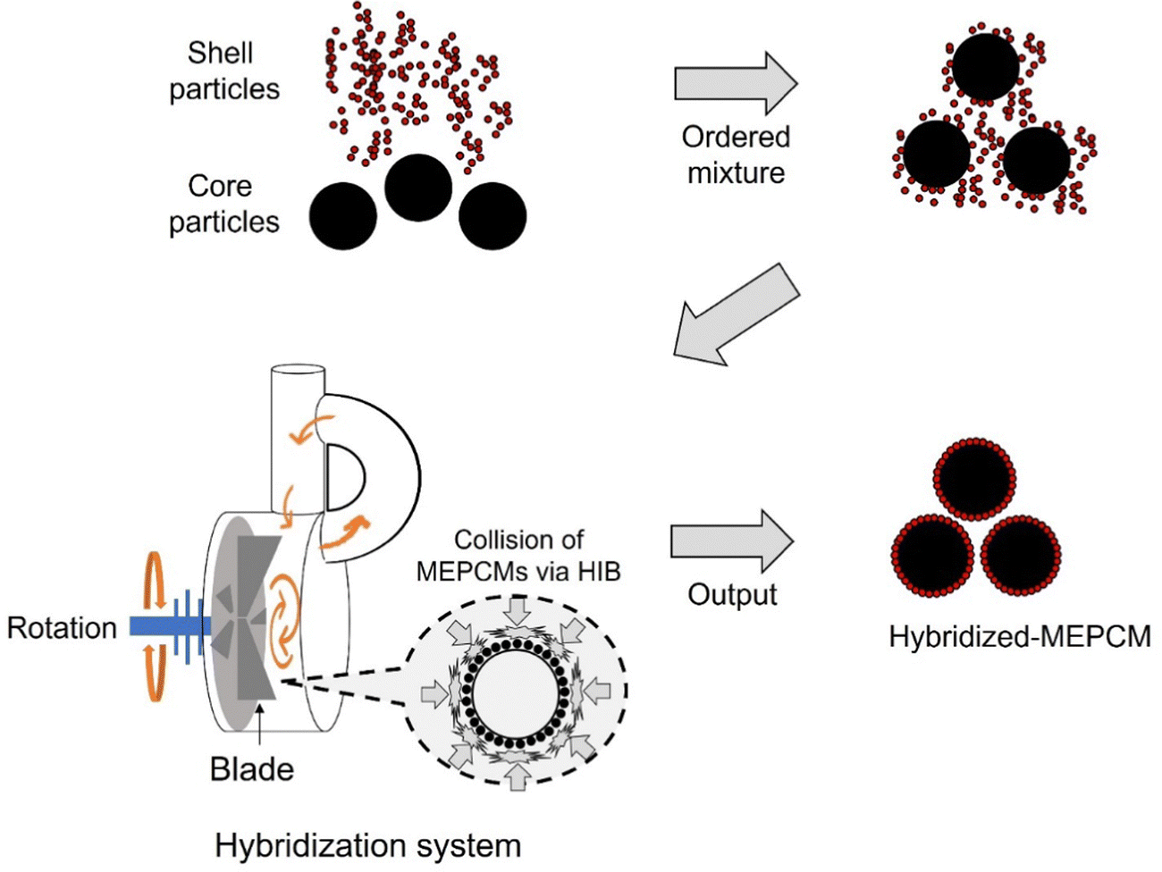 | ||
| Fig. 1 Schematic diagram of the MEPCMs making using the HIB method. | ||
| Shell particle composition | Initial name (before heat oxidation) | Final name (after heat oxidation) |
|---|---|---|
| α-Al2O3 | Hybridized-PCM-alumina | MEPCM-alumina |
| α-Al2O3–45 vol%AlOOH | Hybridized-PCM-alumina-AlOOH | MEPCM-alumina-AlOOH |
| AlOOH | Hybridized-PCM-AlOOH | MEPCM-AlOOH |
Characterization
The morphologies and surface structures of the synthesized MEPCMs were examined using a field-emission scanning electron microscopy (FE-SEM) (JSM-7001FA, JEOL Ltd, Japan). Following the heat-oxidation treatment, the elemental distribution was evaluated by inspecting the cross-sections of the MEPCMs. These cross-sectioned specimens were polished using an ion beam cross-section polisher (IB-09010CP, JEOL Ltd, Japan) before being characterized by energy-dispersive X-ray spectroscopy (EDS) (JSM-7001FA, JEOL Ltd, Japan). The phase composition was determined using powder X-ray diffraction (XRD) equipped with one-dimensional silicon strip sensor (MiniFlex600, Cu Kα, Rigaku, Japan). The prominent XRD peaks were identified corresponding to α-Al2O3 (JCPDS card No. 01-075-6776), AlOOH (JCPDS card No. 01-073-6509), Si (JCPDS card No. 00-005-0565), Al4Cu9 (JCPDS card No. 00-024-0003), and Cu2O (JCPDS card No. 01-077-7719). The melting point and LHS capacity of the MEPCMs were quantified using a differential scanning calorimetry (DSC) analyzer (DSC-823, Mettler Toledo, USA). The cyclic durability over 600 cycles was assessed through thermal cyclic tests in a custom-built quartz furnace capable of lateral movement between two points. The high-temperature stability of MEPCMs was conducted by exposing them to an air environment at 900 °C for 100 h in a muffle furnace.Results & discussion
Observation of MEPCMs
Fig. 2 displays the SEM images of MEPCMs, synthesized using a combination of HIB and heat-oxidation treatment at 1000 °C for three hours. All the hybridized-PCMs consistently exhibit spherical shapes (Fig. 2b–d). Following the HIB treatment, the presence of shell NPs (α-Al2O3, AlOOH) on the PCM core particle is apparent (Fig. 2b–d). Specifically, the α-Al2O3 shell NPs adheres to the particle's surfaces in a spherical form (Fig. 2b), while the AlOOH shell NPs adheres in a plate-like manner (Fig. 2d). Fig. 2c depicts a combination of rounded α-Al2O3 NPs and flat AlOOH NPs attached to the core PCM particle's surfaces.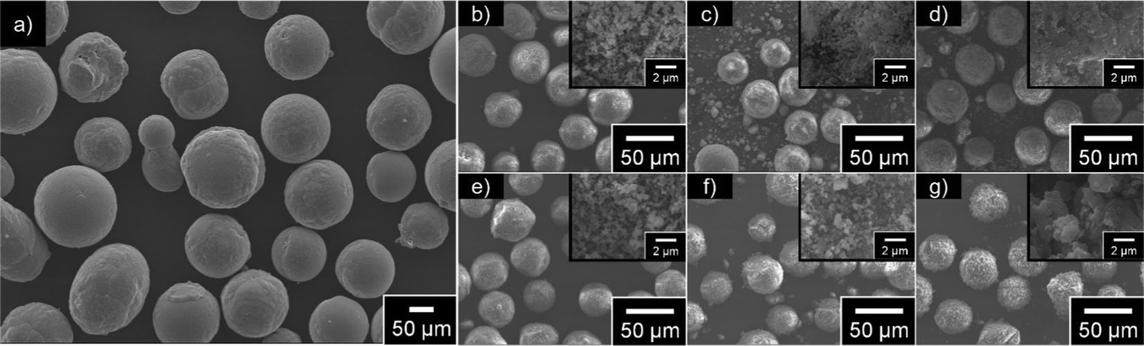 | ||
| Fig. 2 SEM images of the MEPCMs before and after the treatment. (a) Raw material, (b) hybridized-PCM-alumina, (c) hybridized-PCM-alumina-AlOOH, (d) hybridized-PCM-AlOOH (e) MEPCM-alumina, (f) MEPCM-alumina-AlOOH, and (g) MEPCM-AlOOH. MEPCMs in (e)–(g) were derived by heat oxidation treatment of the corresponding HIB-treated MEPCMs from (b)–(d) at 1000 °C for three hours. | ||
Following the heat oxidation treatment at 1000 °C for three hours, all samples preserved their spherical shape, even when processed above the melting point of the Cu–12.8Si–20Al alloy (Fig. 2e–g). No leakage of liquid PCM or damage to the shell was detected, indicating the heat oxidation treatment successfully sintered the shell NPs, resulting in the formation of dense shells. The MEPCM-alumina is uniformly encapsulated by α-Al2O3 shell NPs (Fig. 2e), with minimal variations from its state prior to the heat oxidation (Fig. 2b). Fig. 2g illustrates the MEPCM-AlOOH encapsulated by a dense, seamlessly sintered surfaces. Given that AlOOH dehydrates to form Al2O3 around 500 °C,34 this sintered layer is the result of AlOOH dehydration. Lastly, the surfaces of MEPCM-alumina-AlOOH are dominated by spherical α-Al2O3 shell NPs (Fig. 2f).
Heat oxidation of hybridized-PCM
Hybridized-PCMs formed a stable and dense α-Al2O3 shell by sintering the shell nanoparticles through heat oxidation treatment. Drawing from the findings of Nomura et al., when an Al-based PCM coated with AlOOH undergoes heat oxidation around 1000 °C, a dense and robust Al2O3 shell formed on the PCM surfaces. This formation is primarily due to the dehydration of AlOOH coupled with the partial oxidation of Al.23 Similarly, for hybridized-PCM that was encapsulated with AlOOH/Al2O3 shell nanoparticles, subjecting them to a heat oxidation treatment at 1000 °C instigates the dehydration of AlOOH and the favorable oxidation of specific Al quantities within the PCM (Fig. S2, ESI†). These synergistic reactions facilitate the sintering of shell nanoparticles, leading to the formation of a stable α-Al2O3 shell.Fig. 3 delineates the thermogravimetric (TG) curves of hybridized-PCMs during the heat-oxidation. Apparently, the TG curves of hybridized-PCMs, when coated with AlOOH nanoparticles (Fig. 3), align closely with the trends of MEPCMs having Al-based alloy PCM surfaces, as coated by the hydroxide precipitation treatment.24,35,36 Here, the heat oxidation process can be classified into three distinct stages:35
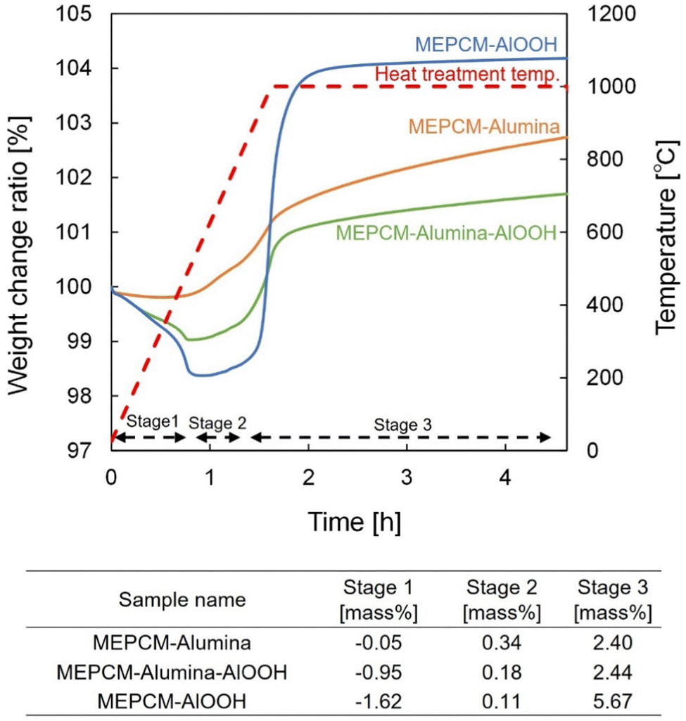 | ||
| Fig. 3 TG curves of hybridized-PCM during heat-oxidation treatment. | ||
(i) Stage 1 – room temperature to 580 °C: this is where dehydration of AlOOH takes place,34 resulting in discernable mass reduction. This decrease becomes more pronounced with an increasing concentration of AlOOH NPs.
(ii) Stage 2 – spanning 580 °C to 738 °C (pre-melting point of PCM): oxidation manifests on the solid-state PCM core surfaces, resulting in the development of a thin oxide film over the PCM core particle.
(iii) Stage 3 – beyond 738 °C (post-melting point of PCM): here, a significant gain is observed, attributable to the acceleration oxidation of Al. Simultaneously, the swift volumetric expansion, might induce tiny cracks in the oxide film. In the PCM transitions to a liquid state, it swiftly permeates these cracks, interacting with oxygen, eventually giving rise to a stable oxide.24
The corresponding yielded composition post-heat oxidation treatment is further corroborated by the XRD pattern result. Fig. 4 exhibits the comparative analysis of the XRD patterns between hybridized-PCMs and developed MECPMs. Both Al4Cu9 and Si in PCM were detected across all samples. Notably, AlOOH was discernible in both hybridized-PCM-AlOOH and hybridized-PCM-alumina-AlOOH. In contrast, in the XRD patterns for MEPCM-AlOOH and MEPCM-alumina-AlOOH, AlOOH peaks were absent, while clear α-Al2O3 peaks were present. Such observations can be linked to the transformation of the AlOOH shell nanoparticles into α-Al2O3, a conversion triggered during the 500 °C heat-oxidation treatment (Fig. 3). Further emphasizing this transformation, the intensity of the α-Al2O3 peak in MEPCM-alumina, MEPCM-AlOOH, and MEPCM-alumina-AlOOH was markedly higher compared to their hybridized-PCM counterparts. Additionally, the absence of copper oxide in hybridized-PCMs, followed by its detection post heat-oxidation, implies the oxidation of a portion of the PCM particles during the treatment.
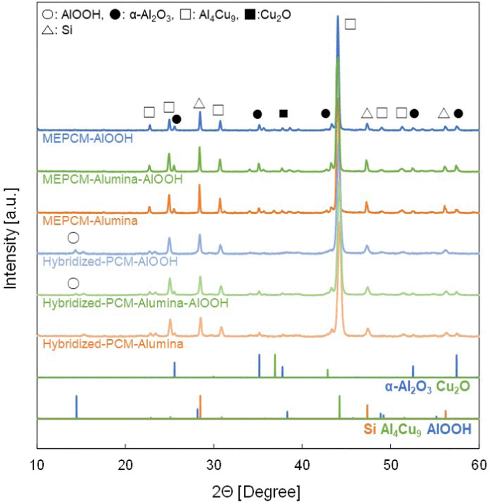 | ||
| Fig. 4 XRD patterns of the MEPCMs after heat-oxidation treatment. | ||
Thermal energy storage and release performance
As illustrated in Fig. 5, the LHS capacity of the MEPCMs increases with the decreasing addition of AlOOH. The melting temperature of the synthesized MEPCMs was approximately 775–780 °C, whereas the solidification temperature ranged from 730–737 °C. The solidification temperature of all MEPCMs was about 45 °C lower than the melting temperature. Such supercooling phenomenon has been reported for other high-temperature MEPCMs.35,37 During solidification, both MEPCM-alumina and MEPCM-alumina-AlOOH exhibited a minor peak around 750 °C. Notably, this peak was absent in the MEPCM-AlOOH. Both MEPCM-alumina and MEPCM-alumina-AlOOH presented similar DSC curves. However, the DSC curve for MEPCM-AlOOH was distinctly different. The concentration of Al in the PCM of MEPCM-AlOOH likely diminished, transitioning from 20% down to approximately 15% due to the significant oxidation of Al in the PCM during the heat oxidation (Fig. 3). Such oxidation elevated the onset temperature of melting for MEPCM-AlOOH (Fig. S1, ESI†). From these observations, it becomes clear that the composition of the shell NPs plays a pivotal role in determining the LHS characteristics of the MEPCMs.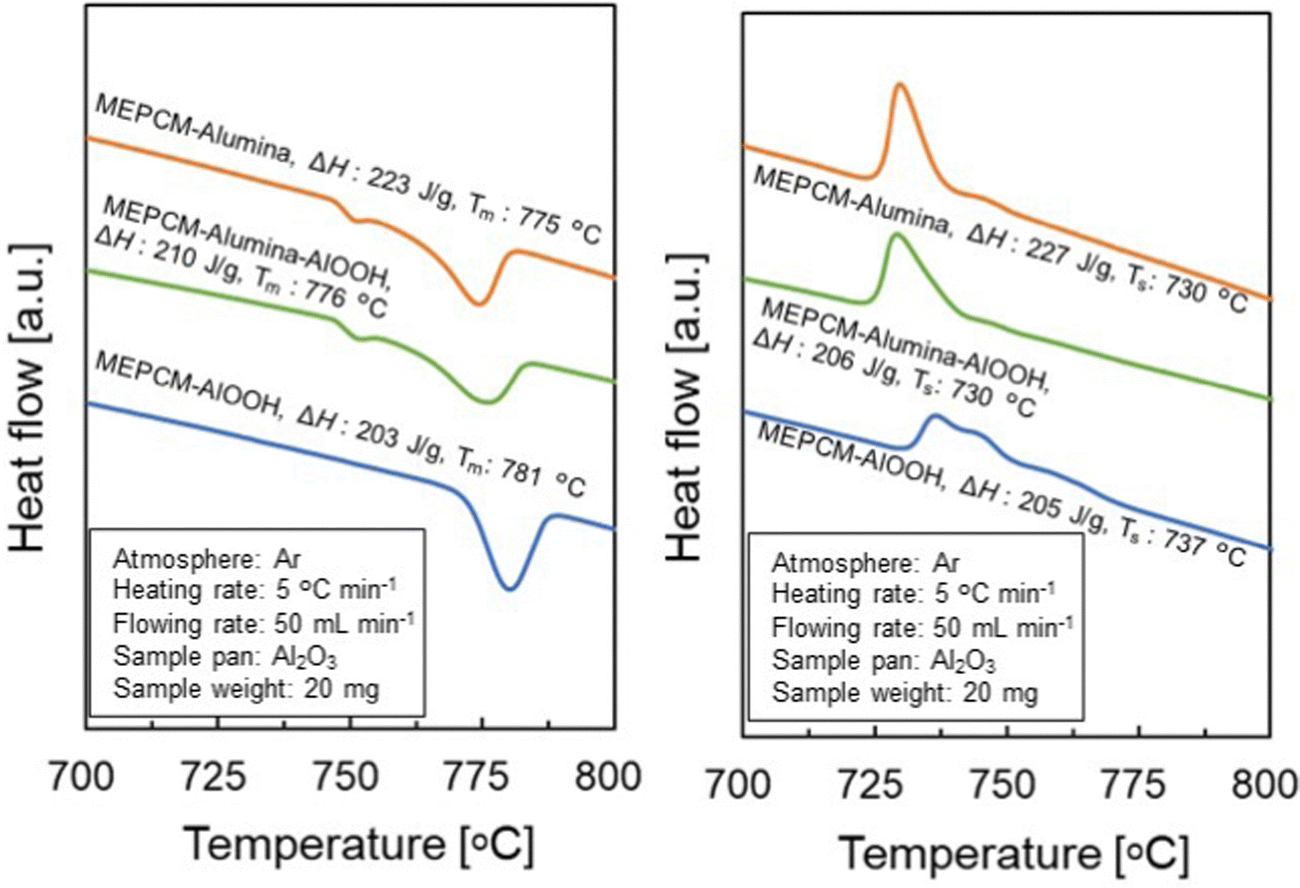 | ||
| Fig. 5 DSC curve of various AlOOH addition MEPCMs after heat oxidation treatment. (Tm: melting temperature of MEPCM, Ts: solidification temperature of MEPCM, ΔH: latent heat storage capacity). | ||
Thermal stability and cyclic durability
To assess the thermal stability of the MEPCMs, these materials were subjected to extensive exposure in air at 900 °C. The structural response and changes in LHS capacity over this period are presented in Fig. 6a and b. Notably, both the MEPCM-alumina and MEPCM-alumina-AlOOH samples exhibited robust structural integrity, retaining their shape even after the extensive 100 h test period. This ability to withstand high-temperature environments speaks to the strength of the binding forces within these materials, as well as the resilience of their microstructures against thermal degradation.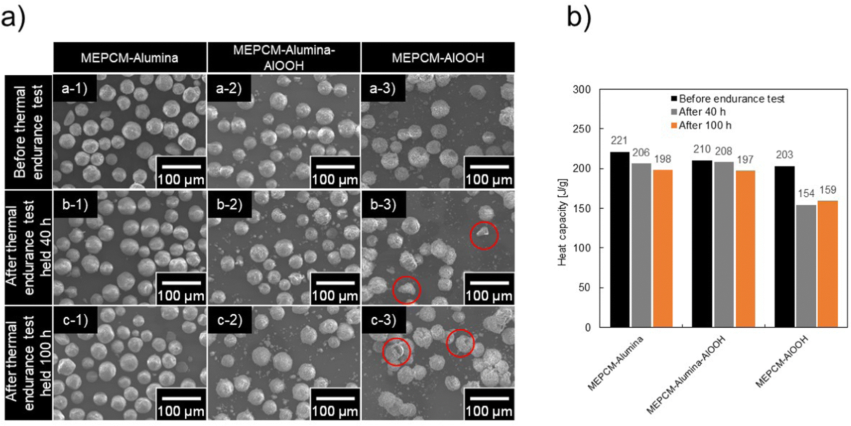 | ||
| Fig. 6 (a) SEM images and (b) LHS capacity of heat–oxidation-treated samples, following thermal endurance test for 40 h and 100 h at 900 °C in air. Samples include MEPCM-alumina, MEPCM-alumina-AlOOH, and MEPCM-AlOOH. Samples with visible shell damage are marked with red circles. | ||
In stark contrast, the MEPCM-AlOOH displayed shell damage around 40 h. Such damage can be attributed to weaker intermolecular forces or potential imperfections in its microstructure, rendering it more susceptible to thermal stresses. Quantifying the LHS capacity post the 100 h thermal test, values recorded were 198 J g−1 for MEPCM-alumina, 197 J g−1 for MEPCM-alumina-AlOOH, and 159 J g−1 for MEPCM-AlOOH (Fig. 6b). When juxtaposed with their initial capacities, these represent reductions to 89.6, 93.8, and 78.3%, respectively. The data asserted that MEPCM-alumina and MEPCM-alumina-AlOOH exhibit superior thermal stability when exposed to high-temperature air.
Progressive heating and cooling cycles were, then, conducted in order to confirm both the LHS capacity and cyclic durability of the MEPCMs. During this cyclic test, the MEPCMs were heated to 865 °C and cooled to 600 °C over 600 cycles. The heating and cooling average rates were approximately 58 °C min−1 and 28 °C min−1, respectively. Fig. 7b and c depict the SEM images of the MEPCMs after 100 and 600 cycles, respectively. Notably, Fig. 7b reveals structural compromises in the MEPCM-AlOOH after just 100 cycles: ruptured shells and evident PCM leakage. Such degradation can be traced back to the inherent stresses introduced by volumetric changes – expansion and contraction – during the phase transitions of the PCM particles.38 However, in a testament to their superior structural stability, both MEPCM-alumina and MEPCM-alumina-AlOOH samples, as seen in Fig. 7c, exhibited remarkable resilience. Even after an exhaustive 600 cycles, they retained their original morphology without any discernible cracks or indications of PCM leakage.
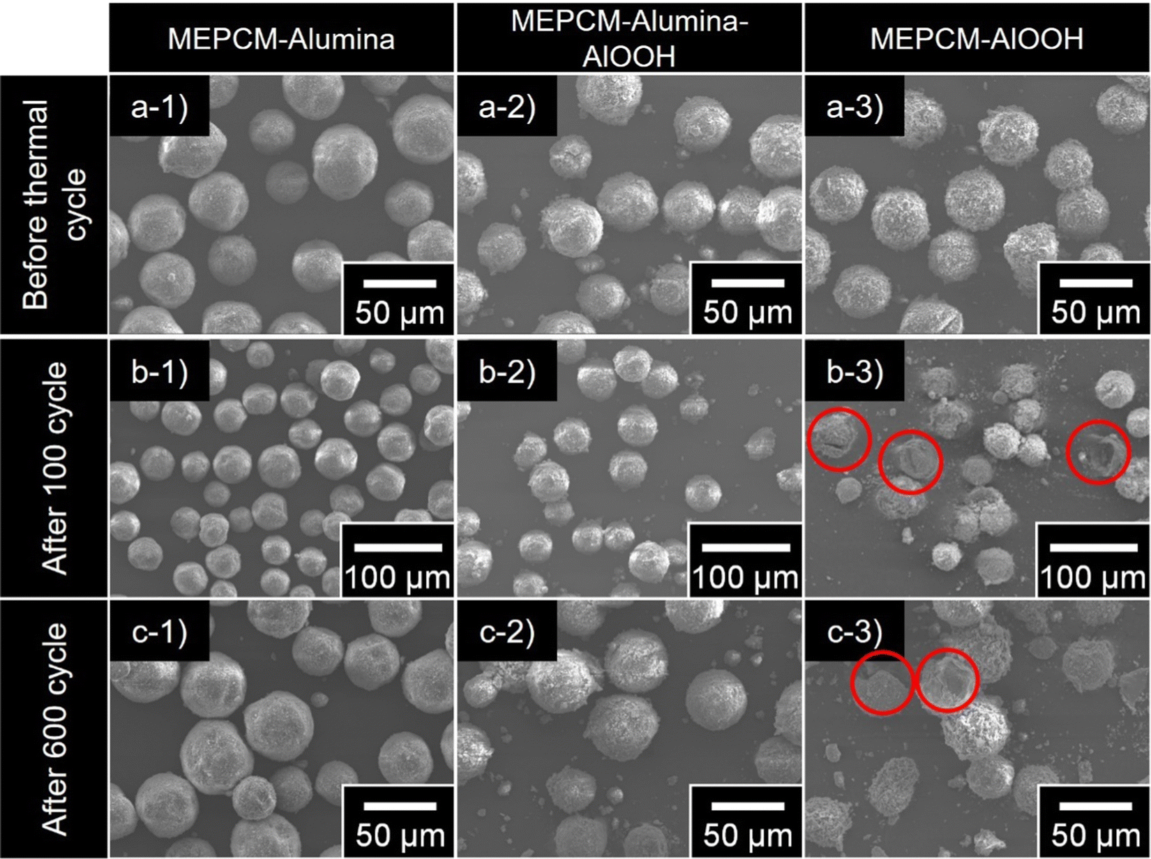 | ||
| Fig. 7 SEM images of (a) heat–oxidation-treated samples after (b) 100 and (c) 600 thermal cycles. Samples include MEPCM-alumina, MEPCM-alumina-AlOOH, and MEPCM-AlOOH. Samples with visible shell damage are marked with red circles. | ||
Fig. 8 presents the heating (a) – cooling (b) DSC curves of MEPCM-alumina, MEPCM-alumina-AlOOH, and MEPCM-AlOOH after 600 cycles of repeated melting and solidification. In Fig. 8b, the solidification temperature remains unchanged after cyclic testing, at approximately 731–738 °C. In contrast, the LHS of melting after 600 cyclic testing is 208 J g−1 for MEPCM-alumina, 203 J g−1 for MEPCM-alumina-AlOOH and 156 J g−1 for MEPCM-AlOOH, decreasing to 91.2, 98.5, and 81.3% of those before cyclic testing, respectively (Fig. 8c). Thus, MEPCM-alumina and MEPCM-alumina-AlOOH maintain high LHS capacity, nearly identical to the as-prepared MEPCMs. To elucidate the compositional changes and oxidation of Cu–Si–Al PCM after 600 cycles, XRD analysis was undertaken (Fig. S3, ESI†). The findings suggest that the majority of the PCM in MEPCM-alumina and MEPCM-alumina-AlOOH remained intact, resisting oxidation throughout the cyclic testing. In contrast, the peak intensity of α-Al2O3 in MEPCM-AlOOH after 600 cyclic tests was higher than that in MEPCM-AlOOH before the cyclic tests. This suggests that the decrease in the LHS capacity of MEPCM-AlOOH was due to shell breakage (Fig. 7) and subsequent oxidation of the PCM.
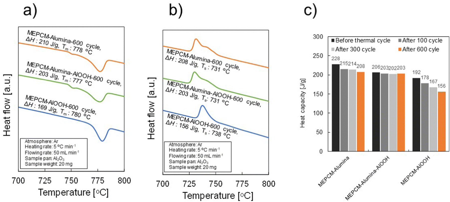 | ||
| Fig. 8 LHS capacity of as-prepared MEPCM-alumina, MEPCM-alumina-AlOOH, and MEPCM-AlOOH samples after 100 cycles, 300 cycles, and 600 cyclic tests. (a) and (b) DSC curves for melting and solidification, respectively. (c) LHS capacity of all samples. (Tm: melting temperature of MEPCM; Ts: solidification temperature of MEPCM; ΔH: latent heat storage capacity). | ||
Further insights into the MEPCM shell cross-section of the as-prepared MEPCMs were sought to understand the encapsulation mechanism and associated mechanical properties. The observation analyses revealed negligible structural changes pre and post 600 cyclic tests (Fig. 9 and Fig. S4–S6, ESI†). Of these, the α-Al2O3 shells of both MEPCM-alumina and MEPCM-alumina-AlOOH were discerned to have a dual-layered composition: an inner layer comprised of tiny sintered NPs, indicative of originating from α-Al2O3 NPs, and an outer layer consisting of aggregated NPs. The sintered shell NPs layer was about 300–400 nm thick, consisting of tiny sintered NPs around 150 nm in size, specifically α-Al2O3 NPs. The thickness of the shell NPs layer was about 1.2 μm. Voids were discerned within the shell NPs layer of MEPCM-alumina, while in MEPCM-alumina-AlOOH, the α-Al2O3 NPs acted as a binder, promoting inter-particle connectivity during its transformation into α-Al2O3 through the sintering process.
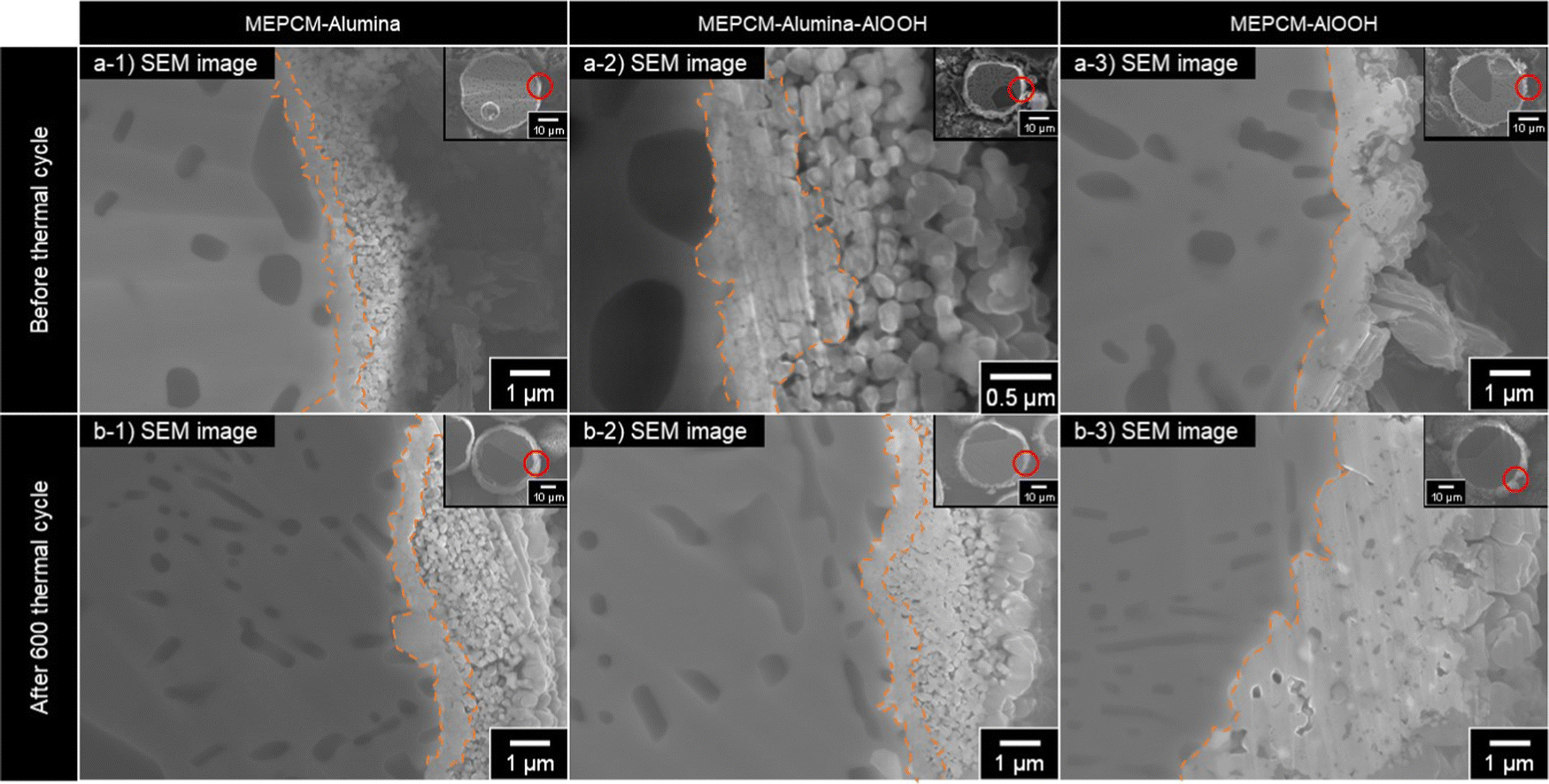 | ||
| Fig. 9 Cross-sectional SEM images of the MEPCMs before and after 600 cyclic tests. Samples include MEPCM-alumina, MEPCM-alumina-AlOOH, and MEPCM-AlOOH. Orange lines indicate the interface between the PCM core and its shell. | ||
Within the shell layer of MEPCM-alumina-AlOOH, the α-Al2O3 shell NPs seemed to have undergone a mild fusion (Fig. S6, ESI†). This mild fusion of the α-Al2O3 NPs indicates that the addition of AlOOH to MEPCM-alumina-AlOOH acted as a binding agent. It aided in linking adjacent α-Al2O3 NPs as they transformed into α-Al2O3 during the sintering process initiated by the heat oxidation treatment. The dual-layered shell structures of MEPCM-alumina and MEPCM-alumina-AlOOH exhibited high durability, retaining their integrity even after 600 cyclic tests (Fig. S4, ESI†). This shell structure effectively protected against PCM corrosion and oxidation and retained 98.5% (MEPCM-alumina-AlOOH) or 91.2% (MEPCM-AlOOH) of LHS capacity after 600 cyclic tests.
In contrast, the MEPCM-AlOOH shell (Fig. 9 and Fig. S7, ESI†) was composed of alumina-sintered bodies, forming a dense structure where individual and sintered shell NPs could not be observed. The thickness of the alumina-sintered layer was approximately 0.2–1 μm, and differences in thickness and density were seen depending on the location. Some areas showed the presence of voids or fragile areas prone to cracking within the sintered body. Compared to MEPCM-alumina and MEPCM-alumina-AlOOH, MEPCM-AlOOH had lower cyclic durability. It is thought that the sintered shell particle layers of MEPCM-alumina and MEPCM-alumina-AlOOH, the sudden expansion pressure associated with the melting of PCM, were distributed by many sintered NPs, contributing to their high durability. On the other hand, since the MEPCM-AlOOH shell is formed from a large sintered body,24 the breakage was likely caused by the failure to distribute the rapid expansion pressure caused by the melting of the PCM, which was received by the vulnerable areas. The inhomogeneity of the MEPCM-AlOOH sintered shell may have contributed to its low durability.
MEPCM-alumina-AlOOH demonstrated higher cyclic durability than MEPCM-alumina (Fig. 8). In the shell NPs layer of MEPCM-alumina-AlOOH, the added AlOOH acted as a sintering agent, causing the α-Al2O3 NPs to fuse. This fusion made the shell particle layer denser and is postulated to have provided more excellent mechanical durability.
Nomura et al. reported that Al–Si/Al2O3 core–shell MEPCMs, prepared by hydrolysis and heat oxidation, exhibit shell formation through two fundamental mechanisms: (1) crack caused by expansion pressure resulting from melting of the PCM core and crack repair by PCM oxidation and (2) oxidation of the PCM surfaces due to oxygen diffusion.36 Similarly, the shell of Cu–Si–Al/Al2O3 core–shell MEPCMs, prepared via HIB treatment and heat oxidation, is thought to form through a comparable mechanism. Fig. 10 presents the expected schematic diagram illustrating the shell formation process during the heat oxidation treatment of MEPCM-alumina. The TG curve of MEPCM-alumina shows a significant weight shift between 538–1000 °C (Fig. 3). When the heat oxidation temperature is below the melting point (580–738 °C), the PCM core particles (Cu–12.8Si–20Al) undergo oxidation and form a γ-Al2O3 oxide film on their surface. If the heat oxidation temperature exceeds the melting point (738–1000 °C), two phenomena occur: (1) the initiation of cracks and subsequent PCM leakage and (2) crack repair through PCM oxidation. These processes are repeated, leading to the formation of an Al2O3 shell.36 Near 950 °C, the generated γ-Al2O3 transitions to α-Al2O3 formation, followed by the sintering of α-Al2O3 shell NPs, which results in the formation of a sintered shell NPs layer.
 | ||
| Fig. 10 Schematic diagram of shell formation by heat oxidation treatment of MEPCM-alumina. (a) After HIB treatment, (b) oxidation of PCM core particles and formation of oxide film, (c) diffusion of PCM due to melting of PCM, and (d) sintered α-Al2O3 shell. | ||
Conclusions
In conclusion, this study has successfully developed a Cu–12.8mass%Si–20mass%Al@Al2O3 MEPCM with excellent thermal cyclic durability and thermal stability by HIB treatment followed by heat oxidation treatment. The effect of shell NPs composition on the shell structure and durability of MEPCMs was investigated. The primary results are as follows.(1) The HIB treatment successfully enabled a uniform coating of the PCM surfaces with shell NPs. After the HIB process, heat oxidation caused the formation of shell NPs sintering and the merging of shell NPs, leading to the construction of a stable α-Al2O3 shell.
(2) MEPCM-alumina and MEPCM-alumina-AlOOH, utilizing α-Al2O3 NPs as a shell, formed a dual-layered shell comprised of a sintered shell NPs layer and a shell-NPs layer. These demonstrated impressive durability over 600 cycles and superior thermal stability in high-temperature air. MEPCM-AlOOH utilizing AlOOH as seamless and dense α-Al2O3 shell was formed.
(3) Incorporating AlOOH NPs into the shell composition enhanced the thermal durability of the shell. During the heat oxidation, AlOOH acted as a binding agent, facilitating the formation of a denser α-Al2O3 shell.
The MEPCM fabrication method that employs HIB treatment offers potential for broader application in the microencapsulation of diverse PCMs, as it is not reliant on specific PCMs or shell NPs. Furthermore, the combined strategy of HIB and heat oxidation treatment holds benefits for mass production and cost efficiency due to its physical process.
Author contributions
Masahiro Aoki: data curation, investigation, writing. Melbert Jeem: data curation, investigation, writing – review & editing. Yuto Shimizu: investigation. Takahiro Kawaguchi: investigation. Minako Kondo: investigation. Tomokazu Nakamura: investigation. Chihiro Fushimi: investigation. Takahiro Nomura: investigation, funding acquisition, project administration, supervision, writing, writing – review & editing.Data availability
The data supporting this study are available from the corresponding author upon reasonable request.Abbreviations
| ΔH | Latent heat storage capacity |
| CSP | Concentrated solar power |
| DSC | Differential scanning calorimeter |
| EDS | Energy-dispersive X-ray spectroscopy |
| HIB | High-speed impact blending |
| LH | Latent heat |
| LHS | Latent heat storage |
| MEPCM | Microencapsulated phase change material |
| SEM | Scanning electron microscopy |
| SHS | Sensible heat storage |
| TES | Thermal energy storage |
| TG | Thermogravimetric analysis |
| T m | Melting temperature |
| T s | Solidification temperature |
| PHP | Power to heat to power |
| VRE | Variable renewable energy |
| NPs | Nanoparticles |
Conflicts of interest
The authors declare no conflict of interest.Acknowledgements
This work was financially supported by Japan Society for the Promotion of Science (JP22H00306). The work was conducted in Hokkaido University, supported by “Advanced Research Infrastructure for Materials and Nanotechnology in Japan (ARIM)” of the Ministry of Education, Culture, Sports, Science and Technology (MEXT).References
- Renewable energy – powering a safer future, https://www.un.org/en/climatechange/raising-ambition/renewable-energy, (accessed February 21, 2023).
- M. K. DeValeria, E. E. Michaelides and D. N. Michaelides, Energy, 2020, 190, 116440 CrossRef CAS.
- S. Wu, C. Zhou, E. Doroodchi, R. Nellore and B. Moghtaderi, Energy Convers. Manage., 2018, 168, 421–453 CrossRef CAS.
- Y. He, S. Guo, J. Zhou, F. Wu, J. Huang and H. Pei, Energy Convers. Manage., 2021, 229, 113779 CrossRef.
- T. Uchino, T. Yasui and C. Fushimi, Energy Convers. Manage., 2021, 243, 114366 CrossRef CAS.
- S. Liu, H. Bai, P. Jiang, Q. Xu and M. Taghavi, J. Energy Storage, 2022, 50, 104577 CrossRef.
- L. Sang, X. Lv, Y. Wang, J. Huang and Y. Wu, J. Energy Storage, 2023, 61, 106724 CrossRef.
- M. Tawalbeh, H. A. Khan, A. Al-Othman, F. Almomani and S. Ajith, Int. J. Thermofluids, 2023, 18, 100326 CrossRef CAS.
- J. Liu, Z. Chang, L. Wang, J. Xu, R. Kuang and Z. Wu, ACS Omega, 2020, 5, 19236–19246 CrossRef CAS PubMed.
- M. Liu, X. Zhang, J. Ji and H. Yan, J. Energy Storage, 2023, 63, 107005 CrossRef.
- C. Li, Q. Li and R. Ge, Energy Rep., 2022, 8, 12740–12764 CrossRef.
- Y. T. Wu, Y. Li, N. Ren, R. P. Zhi and C. F. Ma, Sol. Energy Mater. Sol. Cells, 2018, 176, 181–189 CrossRef CAS.
- M. Opolot, C. Zhao, M. Liu, S. Mancin, F. Bruno and K. Hooman, Renewable Sustainable Energy Rev., 2022, 160, 112293 CrossRef CAS.
- B. Xu, P. Li and C. Chan, Appl. Energy, 2015, 160, 286–307 CrossRef.
- S. C. Costa and M. Kenisarin, Renewable Sustainable Energy Rev., 2022, 154, 111812 CrossRef CAS.
- J. E. Rea, C. J. Oshman, A. Singh, J. Alleman, G. Buchholz, P. A. Parilla, J. M. Adamczyk, H. N. Fujishin, B. R. Ortiz, T. Braden, E. Bensen, R. T. Bell, N. P. Siegel, D. S. Ginley and E. S. Toberer, Energy Convers. Manage., 2019, 199, 111992 CrossRef CAS.
- R. Al-Shannaq, J. Kurdi, S. Al-Muhtaseb and M. Farid, Sol. Energy, 2016, 129, 54–64 CrossRef CAS.
- G. Peng, G. Dou, Y. Hu, Y. Sun and Z. Chen, Adv. Polym. Technol., 2020, 2020, 9490873 CrossRef.
- A. Jamekhorshid, S. M. Sadrameli and M. Farid, Renewable Sustainable Energy Rev., 2014, 31, 531–542 CrossRef CAS.
- X. Wu, M. Fan, S. Cui, G. Tan and X. Shen, Sol. Energy Mater. Sol. Cells, 2018, 178, 280–288 CrossRef CAS.
- M. D. Romero-Sanchez, R.-R. Piticescu, A. M. Motoc, F. Aran-Ais and A. I. Tudor, Manuf. Rev., 2018, 5, 8 Search PubMed.
- B. Zhao, Y. Guo, C. Wang, L. Zeng, K. Gao, N. Sheng, E. Gariboldi and C. Zhu, Chem. Eng. J., 2023, 457, 141352 CrossRef CAS.
- T. Nomura, N. Sheng, C. Zhu, G. Saito, D. Hanzaki, T. Hiraki and T. Akiyama, Appl. Energy, 2017, 188, 9–18 CrossRef CAS.
- N. Sheng, C. Zhu, H. Sakai, Y. Hasegawa, T. Akiyama and T. Nomura, Sol. Energy Mater. Sol. Cells, 2019, 200, 109925 CrossRef CAS.
- T. Kawaguchi, H. Sakai, N. Sheng, A. Kurniawan and T. Nomura, Appl. Energy, 2020, 276, 115487 CrossRef CAS.
- Y. Huang, A. Stonehouse and C. Abeykoon, Int. J. Heat Mass Transfer, 2023, 200, 123458 CrossRef CAS.
- G. Leng, G. Qiao, Z. Jiang, G. Xu, Y. Qin, C. Chang and Y. Ding, Appl. Energy, 2018, 217, 212–220 CrossRef CAS.
- G. Alva, Y. Lin, L. Liu and G. Fang, Energy Build., 2017, 144, 276–294 CrossRef.
- W. J. Tang, Z. Y. Fu, J. Y. Zhang, W. M. Wang, H. Wang, Y. C. Wang and Q. J. Zhang, Powder Technol., 2006, 167, 117–123 CrossRef CAS.
- T. Kawaguchi, H. Nakamura and S. Watano, Powder Technol., 2017, 305, 241–249 CrossRef CAS.
- T. Kawaguchi, H. Nakamura and S. Watano, Powder Technol., 2018, 323, 581–587 CrossRef CAS.
- J. Yang, A. Sliva, A. Banerjee, R. N. Dave and R. Pfeffer, Powder Technol., 2005, 158, 21–33 CrossRef CAS.
- R. Pfeffer, R. N. Dave, D. Wei and M. Ramlakhan, Powder Technol., 2001, 117, 40–67 CrossRef CAS.
- Boehmite Powder/Products, https://www.taimei-chem.co.jp/product/15.html, (accessed September 6, 2023).
- Y. Shimizu, T. Kawaguchi, H. Sakai, K. Dong, A. Kurniawan and T. Nomura, Sol. Energy Mater. Sol. Cells, 2022, 246, 111874 CrossRef CAS.
- T. Nomura, C. Zhu, N. Sheng, G. Saito and T. Akiyama, Sci. Rep., 2015, 5, 9117 CrossRef CAS PubMed.
- T. Kawaguchi, J. Yoolerd, H. Sakai, Y. Shimizu, A. Kurniawan and T. Nomura, Sol. Energy Mater. Sol. Cells, 2022, 237, 111540 CrossRef CAS.
- T. Nomura, J. Yoolerd, N. Sheng, H. Sakai, Y. Hasegawa, M. Haga, G. Saito and T. Akiyama, Sol. Energy Mater. Sol. Cells, 2018, 187, 255–262 CrossRef CAS.
Footnote |
| † Electronic supplementary information (ESI) available. See DOI: https://doi.org/10.1039/d3ma00788j |
| This journal is © The Royal Society of Chemistry 2024 |