
 Open Access Article
 This Open Access Article is licensed under a
 Creative Commons Attribution 3.0 Unported Licence
Segregation in epoxy/amine systems on iron oxide surfaces†
Kieran
Harris
 *a,
Charlie R.
Wand
b,
Peter
Visser
c and
Flor R.
Siperstein
a
*a,
Charlie R.
Wand
b,
Peter
Visser
c and
Flor R.
Siperstein
a
aDepartment of Chemical Engineering, The University of Manchester, Oxford Road, M13 9PL, Manchester, UK. E-mail: kieran.harris@manchester.ac.uk
bNatural Sciences, Faculty of Environment, Science and Economy, Streatham Campus, University of Exeter, North Park Road, EX4 4QF, Exeter, UK
cExpertise Center Corrosion, Akzonobel, Rijksstraatweg 31, 2171 AJ, Sassenheim, The Netherlands
First published on 17th April 2024
Abstract
Segregation of epoxy/amine precursors at solid interfaces can have important consequences in the formation of thin, epoxy–amine films. In this work we study the segregation of a model epoxy molecule (DGEBA) and an amine (MXDA) on different iron oxide surfaces. We found that the extent of segregation can depend on the nature of the solid surface, and that segregation on goethite surfaces is more pronounced than on hematite and magnetite, regardless of the composition of the film. Detailed analysis of the interface shows that the contact layer is not well mixed and regions rich in amine and rich in epoxy molecules can be identified. Furthermore, we suggest that the larger segregation observed in goethite is a consequence of the way the molecules pack on the surface, with stricter binding sites observed at the goethite surface.
1 Introduction
Epoxy resins are commonly used with amine crosslinkers for coatings and structural components due to their adhesive properties, mechanical strength, as well as their chemical and heat resistance.1,2 The properties of epoxy-based coatings can be tailored by changing the chemical structure and mixing ratio of the components, as well as by incorporating pigments and fillers into the formulation, which can provide colour and improve mechanical strength and crack propagation resistance. A recent review shows the advantages and disadvantages of different filler particles in the performance of epoxy resin composites.3 Understanding the interactions between the coating and the surfaces of both substrate and additive particles is important to optimise the coatings formulations in terms of adhesion, wetting, compatibility between the polymer and the substrate, heterogeneity in the cross-linking, durability and performance.Epoxy coatings are essentially prepared by mixing an epoxy precursor with a crosslinker (known also as the curing agent) at a stoichiometric ratio to form a 3-dimensional network with a glass transition temperature significantly above room temperature.1 One possible choice of crosslinker functionality is amines. Epoxy/amine coatings can be brittle and prone to cracking, nevertheless, their properties can be modified by incorporating filler particles such as carbon based materials, metals, fibres, ceramics, and clays among others, in sizes ranging from nm to μm. The performance of the coating can be strongly influenced by the polymer/surface interactions, as well as the structure and composition of the region near the solid surface known as the interphase. The properties of the interphase are known to be different to the properties of the polymer far from the solid surface.4,5
It is known that polymer blends and mixtures containing polymers can segregate at surfaces and interfaces as a result of a balance between enthalpic and entropic contributions. However, predicting the properties of materials that are “chemically complex” is still a challenge,6 with the nanometer scale of the interphase making it particularly difficult to obtain detailed measurements experimentally.7 Despite this, there is experimental evidence of the presence of low crosslink density interphases as a result of surface segregation of epoxy resin components near solid surfaces.8,9
A number of molecular dynamics simulations have been performed to calculate the adsorption energy and structures of epoxy resin precursors at various surfaces.10–15 Yamamoto and Tanaka used molecular dynamics simulations to show that segregation at the resin/metal interface can result from difference in the size of the epoxy precursor and the amine crosslinker, and that the shape of the molecule also plays an important role. Their study was carried out in a system where a stoichiometric mixture of model epoxy precursors and amine crosslinkers were in contact with a pure copper surface, and where electrostatic interactions between the fluid and the solid surface were not considered.16 The presence of surface oxide layers on metals17 is often not considered in computational studies, resulting in the neglect of electrostatic contributions due to surface atom charges.18,19 There is a significant gap in the literature on the computational study of the effects of surface, coating composition and cure conditions on the coating/surface interphase and resulting coating properties.
In this paper, we consider the segregation of epoxy and amine precursors in a non-reacting system to remove the effect of crosslink extent reducing polymer mobility, which will be addressed in a future study. As an example for this study we take a model epoxy/amine system on surfaces that are relevant to the application of corrosion-resistant coatings, focusing on the iron oxides hematite, magnetite, and goethite. While goethite is an iron oxy-hydroxide, for brevity all three surfaces are referred to hereon as iron oxides. In the representative coating mixture, diglycidyl ether of bisphenol A (DGEBA) and m-xylylenediamine (MXDA) are used as epoxy and amine linker species respectively, the molecular structures of which are shown in Fig. 1.
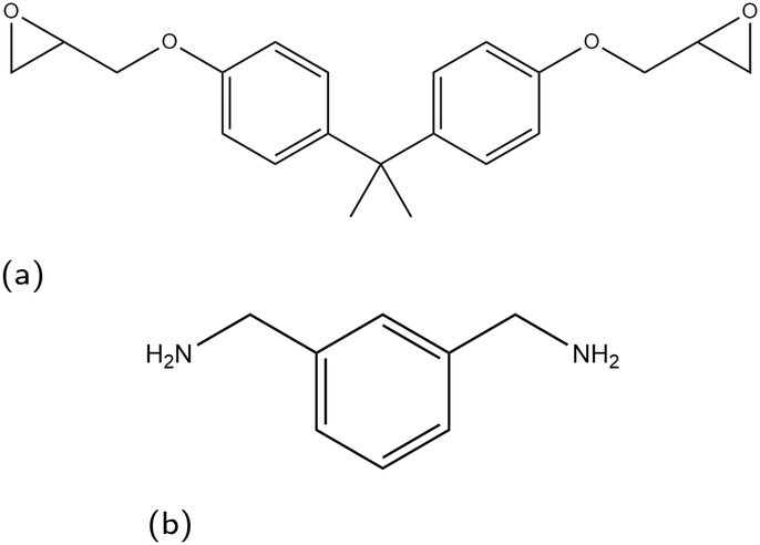 | ||
| Fig. 1 Skeletal structure of monomer species used in this work, (a) DGEBA, (b) MXDA. | ||
2 Methodology
2.1 Computational details
Molecular dynamics simulations are performed using the LAMMPS20 software. The Nosé–Hoover thermostat21 and barostat22 algorithms are used to maintain constant temperature and pressure respectively where relevant. All simulations are performed using a time step of 1 fs. To model the interactions of the liquid monomer molecules, the OPLS-AA force field23 is used, which is parameterised to give accurate potentials for liquid organic systems and atomic partial charges are calculated using the 1.14*CM1A-LBCC algorithm.24 Different methods have been reported in the literature to calculate charges of atoms in epoxy amine polymers.25–27 The method used in this work has shown to give correct thermal and mechanical properties of the polymer,25 and in simulations used to parameterise coarse grain models that were successfully used to calculate glass transition temperatures.26 Other methods reported in the literature are also able to accurately reproduce experimental observations,27 but it is beyond the scope of the paper to compare the advantages and disadvantages of the different methods available.To model the solid surface atoms, the ClayFF force field28 was used with the Kerisit modifications shown to more accurately model iron oxides applied to all iron atoms.29–31 Periodic boundary conditions are used in all three directions and the particle–particle–particle–mesh (PPPM) solver is used for long-range electrostatic corrections.32 The structures of the solid surfaces were constructed using crystallographic information available in the literature,33–35 with slab thicknesses in the z-direction of approximately 30 Å. In the x- and y-directions, the slab dimensions are 82.164 × 71.156 Å2 for hematite, 83.965 × 83.965 Å2 for magnetite and 82.44 × 81.346 Å2 for goethite. We have chosen the (0001) face for hematite and (100) (Pnma space group) for goethite, which are the most thermodynamically stable faces.36,37 For magnetite, we consider the (100) face, which is one of the most prominent growth faces.38,39 Additionally, the magnetite slab is duplicated, rotated 180° and placed ca. 2 Å below the existing slab (Fig. 2b), to remove simulation artefacts caused by the polarity of the surface. Images and a description of the surface structures, as well as details on the simulations artefacts and on force field parameters and atom charges used are given in the ESI.†
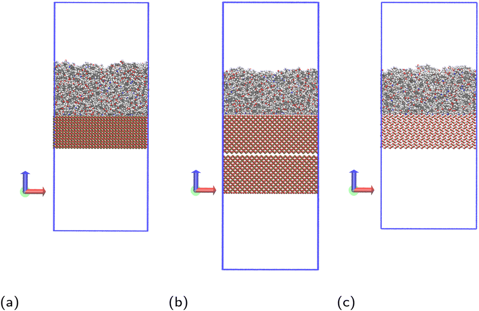 | ||
| Fig. 2 Simulation systems shown for monomer mixture at (a) hematite, (b) magnetite and (c) goethite, with carbon atoms shown grey, hydrogen shown white, oxygen shown red, nitrogen shown blue and iron shown ochre. The periodic box bounds are shown as a blue outline. An additional, inverted slab of magnetite is included to prevent simulation artefacts detailed in the ESI.† | ||
A random arrangement of liquid organic molecules was generated using the PACKMOL program.40 LAMMPS input files were then generated from the PACKMOL structure output by the Moltemplate tool.41 The x and y dimensions of the box are chosen to exactly match the dimensions of the surface onto which the liquid film will be introduced. The z dimension is chosen to be 100 Å, giving low enough density that PACKMOL will be able to find a suitable packing solution (ca. 0.5 g mL−1, half the expected room temperature density of the mixture).
Prior to introduction of the surface, the liquid film must be equilibrated and complete mixing ensured. A full bulk film equilibration simulation without surface would result in a number of molecules partway across the periodic boundary in the z-direction. When the box is extended to incorporate the surface and vacuum regions, these molecules would be suddenly sliced by the added volume. To avoid this, artificial harmonic force walls were used in the z direction with the potential,
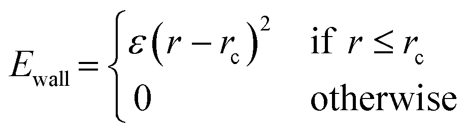 | (1) |
The monomer mixing methodology is adapted from the preparation part of the polymer crosslinking methodology of Demir and Walsh,42 as the intention is to produce a well-mixed binary monomer mixture. The first step involves high-temperature mixing in the NVT ensemble at 1000 K for 0.4 ns followed by cooling to 500 K over 0.5 ns and a further 0.1 ns at 500 K. A temperature of 500 K is high enough to promote monomer mobility and mixing, without being so high as to produce an unphysical structure. Finally, an NPzT simulation is run in which the box z dimension is allowed to fluctuate while the x and y dimensions remain fixed with a pressure of Pz = 1 atm for 0.5 ns. Note that the positions of the harmonic walls are associated with the upper and lower bounds of the simulation box in the z direction during NPT simulation and so move as the box dimensions change.
Total mixing is ensured using 5 repetitions of an annealing cycle, increasing the temperature to 1000 K and cooling the system back down to 500 K. To verify the system had equilibrated and reached a completely mixed state, the DGEBA–DGEBA, DGEBA–MXDA and MXDA–MXDA radial distribution functions (RDFs) are calculated over each constant 500 K simulation period between annealing cycles. Ideal mixing is reached when these RDFs show no significant changes between two cycles. More details are available in the ESI.†
Before introducing the surface, the film undergoes all but the final cooling step of the annealing cycle. The simulation box is then extended in the z direction to 200 Å for hematite and goethite, and 235 Å for magnetite, to give vacuum regions of approximately 100 Å. The lower harmonic wall is switched off and the solid slab is positioned with the centres of its topmost atoms at the z coordinate the lower harmonic wall was previously at. This results in sufficient separation between liquid and solid atoms that there are no extreme forces due to overlap, while placing the two close enough that little movement of the liquid as a whole is required for ideal contact with the surface. The resulting simulation systems are shown in Fig. 2.
After introduction of the surface, the system was cooled using the NVT ensemble over 0.5 ns to 323 K, chosen to be representative of temperatures used for DGEBA–MXDA coatings in both industry and experiment.43 Variation in temperature was found to have negligible effect on the segregation behaviour of the films at any surface, as shown in the ESI.† Finally, the system is simulated in the NVT ensemble for 1.0 ns at constant temperature. The results obtained for 323 K are shown in the main paper and the discussion on temperature effects is included in the ESI.† Segregation properties are determined as an average over this final 1.0 ns. Neither increasing the simulation time to 2 ns, or use of an additional constant temperature equilibration prior to structure analysis were found to significantly affect segregation results but required significantly more computational resources. More details are available in the ESI.† Five independent simulations with different initial film configurations were averaged over for each condition.
Since each amine is able to react with two epoxide functionalities, the ratio of DGEBA to MXDA must be 2![[thin space (1/6-em)]](https://www.rsc.org/images/entities/char_2009.gif) :1. Therefore, the stoichiometric DGEBA/MXDA monomer film used for the majority of this work is composed of 400 DGEBA and 200 MXDA molecules. Compositions of any other mixtures used are given in the ESI.†
:1. Therefore, the stoichiometric DGEBA/MXDA monomer film used for the majority of this work is composed of 400 DGEBA and 200 MXDA molecules. Compositions of any other mixtures used are given in the ESI.†
2.2 Analysis
The linear concentration normal to the interface (i.e. along the z direction) is calculated in slices of dz = 0.1 Å using the linear density function of the Python library MDAnalysis,44,45 with configurations taken every 1 ps. The position of the solid surface is defined as the centre of the topmost atoms, placed at z = 0 Å. From these linear concentration plots, we quantify the number of adsorbed species by integrating the first adsorption peak. The cutoff in the z direction for the adsorption peaks was defined as 4 Å, 5 Å, and 3 Å for hematite, magnetite and goethite respectively, based on the plotted linear concentrations (section 3.1).Previous work has found that the epoxide oxygen and nitrogen atoms are key adsorbate atoms for DGEBA and MXDA respectively as they are the atoms observed to bind most strongly to the surface in the simulations.8,11,43,46 Therefore, we define a bound molecule as a molecule containing both adsorbing heteroatoms (epoxide oxygen or amine nitrogen for DGEBA or MXDA respectively) within the first adsorption peaks of the linear concentration plots. Since both DGEBA and MXDA have a central plane of symmetry it is possible for one side to bind but not the other, resulting in a “half-bound” molecule. We characterise fully bound molecular binding modes through the distribution of intramolecular distances between the adsorbing heteroatoms and the z distance between the surface and central regions of each species (Fig. 3). Half-bound molecules are not considered in the binding mode plots, as their descriptors are unaffected by the surface type and the noise in the heat maps obscured the fully bound results. Binding mode heat maps including the contributions of both fully- and partially-bound molecules are included in the ESI† for reference. Across all three surfaces, approximately 25% of adsorbed DGEBA molecules and 70% of adsorbed MXDA molecules were fully bound. We do not distinguish between half- and fully-bound molecules in any other analysis.
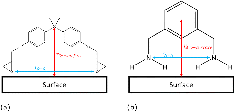 | ||
| Fig. 3 Definitions of configurational descriptors used for investigating the binding modes of (a) DGEBA and (b) MXDA to surfaces. | ||
3 Results and discussion
3.1 Stoichiometric mixtures
The linear concentration plots of key adsorption atoms (epoxide oxygen and amine nitrogen) of a DGEBA/MXDA monomer film at 323 K on all three surfaces averaged over 5 starting configurations are shown in Fig. 4. The concentrations shown are of only the epoxide oxygen atoms and amine nitrogen atoms as representative atoms of DGEBA and MXDA binding respectively. The total density profile of the molecules present in the mixture is available in the ESI† showing a film with practically constant density throughout its thickness except in the 10 Å adjacent to the solid surface. The extremely sharp and tall initial peaks are due to the epoxide and amine groups binding strongly to the iron oxide surfaces, resulting in a high density of epoxide oxygen and amine nitrogen atoms very close to the surface. The total density profile of the film shows a contact layer density higher than the film far from the surface by a factor of 3, 2.5 and 1.7 in the case of hematite, magnetite and goethite respectively, while the amount of epoxide oxygen or amine nitrogen in the contact layer is between 10 and 20 times larger than in the bulk film. Furthermore, the subsequent approximately 2 Å low concentration region in Fig. 4 verifies that both species bind to the surfaces primarily through the epoxide and amine groups, as this region is non-zero in the total density plots, so is populated by the hydrocarbon parts of the molecules. Fig. 4d–f show cross-sectional images of the films where alignment near the solid surface of both nitrogen and oxygen atoms can be easily distinguished. This is consistent with the contact layer shown in the total density profile in the ESI† being wider than the contact layers shown in Fig. 4, extending to approximately 5 Å. This ordering of orientation of both species results in some structure within the region up to 15–20 Å from the surface, but no significant ordering is seen any further from the surface. Details on the analysis of the structure of the molecules near the surface are in section 3.4.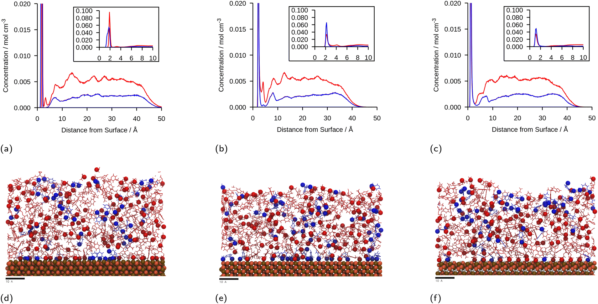 | ||
| Fig. 4 Linear concentration plots of DGEBA (red) and MXDA (blue) as a function of distance from the surface, z, at 323 K in the presence of: (a) hematite; (b) magnetite; (c) goethite. Each plot is calculated from the average of 5 simulations that are identical except for the starting configuration and contains a magnified inset, showing the adsorbate peaks more clearly to highlight the relative widths, heights and positions of the adsorbate peaks with different surfaces and adsorbates. Figures (d–f) show ca. 5 Å slabs of one of each of the systems with segregation close to average at hematite, magnetite and goethite respectively. DGEBA molecules and MXDA molecules are shown in red and blue respectively, with adsorbing atoms (DGEBA epoxide oxygen and MXDA nitrogen) highlighted with spheres. Surface atoms are shown as ochre, orange and white spheres for iron, oxygen and hydrogen atoms respectively. Scale bars correspond to 10 Å. | ||
The position of the adsorption peak for both species depends on the surface, with the peak distance from the surface increasing for goethite < hematite < magnetite due to the different interactions with the topmost atom species. For both hematite and magnetite, the interaction with the surface is dominated by electrostatic interactions. The topmost surface of hematite consists of positive iron ions, whilst magnetite has a mix of positively and negatively charged ions meaning that the hematite surface acts as a purely attractive surface to the electronegative adsorbing atoms, whilst the magnetite acts as a primarily neutral surface. In goethite, the first peak is closer to the surface, consistent with the ‘bridging’ binding conformation identified in previous works where the electronegative atoms sit in pockets or wells and form synergistic hydrogen bonds with the surface OH alongside the electrostatic interactions.8,43
It is generally clear from the first peaks seen in Fig. 4 that the ratio of MXDA:DGEBA adsorbed at the surface is larger than the overall composition ratio of 0.5, i.e. 1 MXDA:2 DGEBA. This indicates that MXDA adsorbs more favourably than DGEBA to all three iron oxide surfaces studied. Adsorption peaks were integrated to determine quantities of adsorbed species and the ratios of MXDA:DGEBA molecules adsorbed at the surfaces. It is important to note that the intensity of the DGEBA peak in hematite is larger than for MXDA, but the width of the peak of MXDA is larger as a result of two overlapping peaks that represent two adsorption modes, as seen in section 3.4. Nevertheless the area of the MXDA peak is larger than the one for DGEBA, indicating a preferential adsorption of MXDA in the contact layer. The results for the stoichiometric monomer film are shown in Fig. 5 where it is clear that segregation is observed in all surfaces, but to a larger extent in goethite. The tendency of MXDA to favourably adsorb to the surface can be the result of both entropic and enthalpic contributions. Yamamoto and Tanaka have shown that smaller molecules preferentially adsorb to surfaces in the absence of electrostatic interactions,16 and in our case, MXDA is smaller than DGEBA. Additionally, the larger negative charge on the MXDA nitrogen atom (−0.90755) compared to the DGEBA epoxide oxygen (−0.3343) means electrostatic attraction to the surface is generally greater for MXDA over DGEBA. The excess MXDA at the surface means that the film is slightly depleted from MXDA far from the surface, which is discussed in more detail in section 3.2.
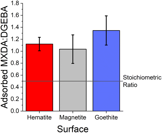 | ||
| Fig. 5 Ratio of adsorbed MXDA:DGEBA for the stoichiometric DGEBA/MXDA monomer film at 323 K in the presence of hematite (red), magnetite (grey) and goethite (blue). Ratios are calculated by comparing the area of MXDA nitrogen and DGEBA epoxide oxygen adsorption peaks. Error bars show ±1 standard deviation, calculated from 5 independent simulations of the system. | ||
As can be seen from the large error bars in Fig. 5, there is significant variation in the adsorbate ratios between individual simulations. This is partially due to the small size of the simulated systems. Since only an approximately 8 × 8 nm2 area of surface is simulated, just under 100 total molecules can adsorb to the surface before total coverage. Therefore, the exchange of a small number of adsorbate molecules can result in a significant change in the ratio of adsorbed MXDA:DGEBA. However, the average obtained here compares well to the value obtained in a larger simulation, detailed in the ESI.† Additionally, on the nanosecond timescales of simulations, we find desorption (and therefore adsorbate exchange) is an extremely rare event. Hence, increased simulation times would not significantly improve the precision of the adsorbate ratios calculated from simulations. Instead, multiple repeats with different but equivalent initial film configurations were used to calculate average values.
3.2 Composition dependence
MXDA adsorbs preferentially on the three surfaces studied independently of the composition as shown in Fig. 6. Various models can be used to describe the composition dependence on adsorption. A simple approximation is described in the ESI,† where the mole fraction of component i in the adsorbed layer yi is given by the following equation: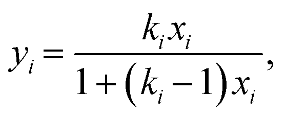 | (2) |
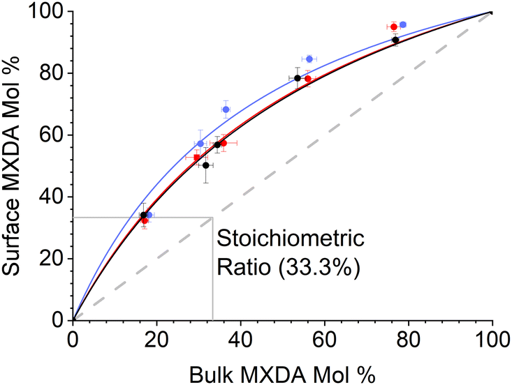 | ||
| Fig. 6 Surface percent MXDA composition against bulk percent MXDA composition on hematite (red), magnetite (black) and goethite (blue). Error bars show ±1 standard deviation, calculated from 5 independent simulations of the system at 323 K. Note that a 2:1 MXDA:DGEBA ratio is an MXDA mol fraction of 33%. | ||
The fitted values of kMXDA for each surface were 2.59 ± 0.15 (hematite), 2.52 ± 0.12 (magnetite) and 3.15 ± 0.28 (goethite). A kMXDA of 1 indicates no preferential adsorption, and larger values indicate stronger preferential adsorption of MXDA. This shows further that hematite and magnetite exhibit similar degrees of segregation, while goethite consistently shows more segregation than the other two surfaces. The preferential adsorption of MXDA is observed at all compositions. It is possible that the presence of MXDA on the goethite surface promotes adsorption of other MXDA molecules because the measured segregation at the lowest concentration simulated is slightly less than what the model would predict. Segregation in hematite and magnetite are well described by the model. Strong MXDA–MXDA interactions can be associated to ordering of these molecules. This will be discussed in the next section.
3.3 Contact layer microstructure
The contact layer microstructures of stoichiometric MXDA:DGEBA compositions are shown in Fig. 7. The epoxide oxygen and nitrogen atoms highlighted can be seen to adhere primarily to specific adsorption sites on the surface, replicating the hexagonal, diagonal and square crystal structures of the hematite, magnetite and goethite surfaces respectively. Fig. 7c and f also show a number of “empty” regions at the goethite surface with no directly adsorbed molecules. A small amount are also observed at the magnetite surface and none at the hematite surface. The significant presence of these gaps at goethite may be attributed to the strict binding sites and comparatively large sizes of the adsorbates, meaning that these open spaces may not contain an accessible adsorption site, leading to this space being filled by a more weakly binding hydrocarbon part of a molecule. Open sites at surfaces such as these may have significant impacts on the corrosion resistance of coatings if water is able to adsorb within these pockets as this could work to initiate blister formation between the coating and surface. This is indicated in Fig. 8, in which it can be seen that as many as 7 water molecules may be able to adsorb to the surface in some regions.
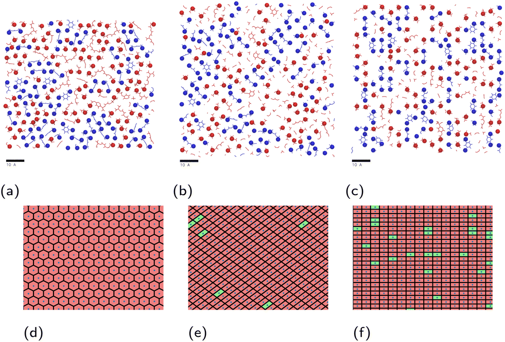 | ||
| Fig. 7 Render of atoms composing the approximate surface-adsorbed layer, i.e. those within 4 Å of the topmost atoms of (a) hematite; (b) magnetite; (c) goethite. Adsorbed epoxide oxygen and amine nitrogen atoms are highlighted as spheres. DGEBA molecules are shown in red, while MXDA molecules are shown in blue. Corresponding plots (d–f) depict occupied (red) and unoccupied (green) regions around each surface iron atom (blue points). Scale bars correspond to 10 Å. | ||
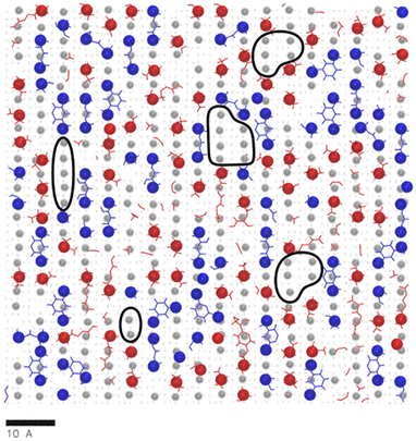 | ||
| Fig. 8 An overlay of Fig. 7c with a render of the adsorption of water oxygen atom adsorption sites (grey circles) at the same goethite surface, from previous work.47 Surface regions devoid of monomer atoms that could contain a number of water molecules are circled in black. A scale bar indicating 10 Å is included. | ||
In the previous section, it was observed that the presence of MXDA on the surface of goethite promotes the adsorption of further MXDA. A close analysis of the contact layers at different film compositions in Fig. 9 show a strong ordering and orientation of MXDA molecules at goethite, which is not observed as clearly at the hematite or magnetite surfaces. Unlike MXDA, DGEBA molecules do not conform to this order, particularly when mixed with MXDA molecules as in the stoichiometric film. As MXDA concentration increases, larger regions of ordered and efficiently packed MXDA molecules are able to form, favouring the adsorption of additional MXDA molecules to the surface.
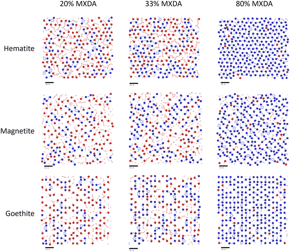 | ||
| Fig. 9 Renders of surface-adsorbed atoms as shown in Fig. 7, showing structures of surface layers at each surface with film compositions in DGEBA excess (20% MXDA), stoichiometric (33% MXDA) and MXDA excess (80% MXDA). DGEBA molecules are indicated in red, and MXDA molecules are indicated in blue. Scale bars of 10 Å are shown beneath each image for reference. | ||
3.4 Monomer adsorption modes
A better understanding of the conformation of the adsorbed molecules can be obtained by looking at the probability distribution of rO–O and rN–N as a function of the molecule's position normal to the surface focusing on the central atom in DGEBA (rCT–surface) and centre of the aromatic ring in MXDA (rAro–surface) as shown in Fig. 10. It is clear that the surface structure plays an important role in the conformation of the molecules. For example, DGEBA on magnetite (Fig. 10c) is most likely to be flat on the surface with low rCT–surface as shown by structures (ii) and (iii) with a very small probability of having the hydrocarbon part of the molecule raised from the surface with high rCT–surface (Fig. 10c(i)). The probability of finding high rCT–surface is significantly larger on hematite (Fig. 10a(i) and (ii)). On the other hand, goethite shows almost a continuum distribution for rCT–surface between 4–8 Å for rO–O 12–13 Å (Fig. 10e(ii) and (iii)). The high probability of finding high rCT–surface in goethite can be attributed to the atomic-scale roughness of the surface. This leaves few surface atoms that can interact strongly with the short-range dispersion interaction dominated hydrocarbon part of the monomers, hence negligible attraction of this part to the surface. Conversely, magnetite has a more atomically smooth surface, leading to much stronger binding of the hydrocarbon part and lower average rCT–surface. These binding mode trends are also observed in single monomer adsorption simulations.8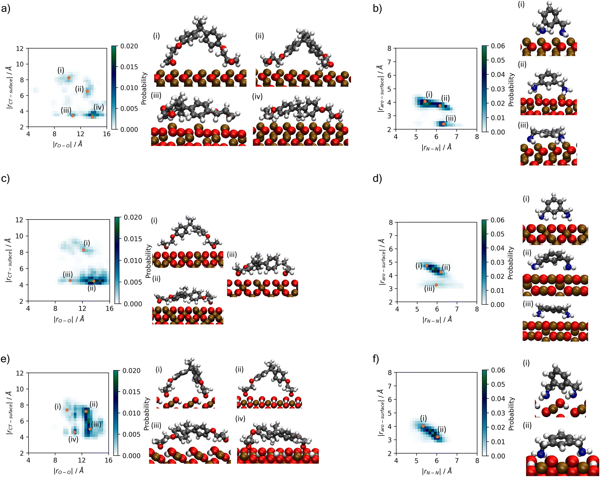 | ||
| Fig. 10 Histograms showing probability of binding modes based on descriptors rO–O and rCT–surface for DGEBA, and rN–N and rAro–surface for MXDA (Fig. 3). Renders of sample structures are shown beside each histogram, with the associated points on the histogram indicated by orange dots with roman numerals matching the renders. Plots are shown for (a) DGEBA on hematite; (b) MXDA on hematite; (c) DGEBA on magnetite; (d) MXDA on magnetite; (e) DGEBA on goethite; (f) MXDA on goethite, and are calculated as averages over 5 repeats of the full 1 ns simulation of the stoichiometric monomer film at each surface. Molecules are only considered fully adsorbed if both key adsorbate atoms are in the first adsorption layer (see Fig. 4). Bulk rO–O and rN–N distributions are plotted in the ESI.† | ||
Some differences can also be seen by comparing monomer conformations in the bulk and near the surface. In bulk, the average rO–O is 14 Å and for rN–N is 6.5 Å, as shown in the ESI.† The hematite and magnetite surfaces induce little change on the conformations of the molecules, with no significant changes to the distribution of DGEBA rO–O, and a slight decrease of rN–N. When adsorbed to goethite, both are reduced significantly, with an average rO–O of 13 Å and very low probabilities of rN–N exceeding 6 Å. The change in conformation of both molecules can be attributed to the strong adsorption sites uniquely present at the goethite surface.
4 Conclusions
Our simulations show significant preferential adsorption of MXDA over DGEBA to all three iron oxides investigated. This can be partially explained as a result of entropic effects, with MXDA being a smaller adsorbate than DGEBA and therefore entropically favoured. However, the observation of differing degrees of segregation at different surfaces shows that enthalpic effects also play an important role, with the highly polar MXDA amine groups providing stronger electrostatic adsorption to the ionic surfaces than the epoxide groups of DGEBA.Goethite exhibits the strongest segregation effects of the three surfaces. Hematite and magnetite show relatively similar behaviour, with the difference between the segregation degrees of the surfaces being very small in comparison to the segregation as a result of the presence of iron oxide surfaces, as well as the uncertainty in the results. These findings suggest that some differences in segregation can be observed depending on the surface and that enthalpic contributions should not be excluded, even when in some cases entropic contributions may be the leading factor for the adsorption behaviour.8 It is important to note that over larger scales and longer times, the effects of processes too slow to be captured by MD simulations such as exchange of adsorbates may influence the difference in segregation behaviour observed. Additionally, since this work was completed, updates to the interface force field48 claim to achieve superior accuracy to ClayFF in modelling metal oxides, so may be of interest in future studies.
This work highlights that chemical features such as surface functionality may affect the segregation behaviour of epoxy/linker mixtures, altering cured coating properties near interfaces with substrates and additive particles alike.
Author contributions
KH – investigation, methodology, formal analysis, writing (original draft, review and editing). CRW – conceptualisation of the work, methodology, formal analysis, writing (review and editing). FRS – conceptualisation of the work, supervision, formal analysis, writing (review and editing). PV – conceptualisation of the work, writing (review and editing).Conflicts of interest
There are no conflicts to declare.Acknowledgements
KH and CRW acknowledge AkzoNobel, and the EPSRC (grant number EP/S004963/1) for materials and financial support. The authors would like to acknowledge the assistance given by Research IT and the use of the Computational Shared Facility at The University of Manchester. Useful discussions with Simon Gibbon and Richard Jones are gratefully acknowledged.Notes and references
- F.-L. Jin, X. Li and S.-J. Park, J. Ind. Eng. Chem., 2015, 29, 1–11 CrossRef CAS.
- A. K. Naskar, J. K. Keum and R. G. Boeman, Nat. Nanotechnol., 2016, 11, 1026–1030 CrossRef CAS PubMed.
- F. A. Gonçalves, M. Santos, T. Cernadas, P. Alves and P. Ferreira, J. Mater. Sci., 2022, 57, 15183–15212 CrossRef.
- H. K. Nguyen, A. Shundo, X. Liang, S. Yamamoto, K. Tanaka and K. Nakajima, ACS Appl. Mater. Interfaces, 2022, 14, 42713–42722 CrossRef CAS PubMed.
- B. B. Johnsen, A. J. Kinloch, R. D. Mohammed, A. C. Taylor and S. Sprenger, Polymer, 2007, 48, 530–541 CrossRef CAS.
- G. E. Stein, T. S. Laws and R. Verduzco, Macromolecules, 2019, 52, 4787–4802 CrossRef CAS.
- S. N. Goyanes, F. Saavedra, A. J. Roncaglia and G. H. Rubiolo, J. Appl. Polym. Sci., 2005, 98, 891–895 CrossRef CAS.
- S. Morsch, C. R. Wand, S. Emad, S. Lyon, F. Siperstein, M. Malanin, J. Muche, A. Caspari, A. Drechsler, K.-J. Eichhorn and S. Gibbon, J. Colloid Interface Sci., 2022, 613, 415–425 CrossRef CAS PubMed.
- M. Aoki, A. Shundo, K. Okamoto, T. Ganbe and K. Tanaka, Polym. J., 2019, 51, 359–363 CrossRef CAS.
- T. Krüger, M. Amkreutz, P. Schiffels, B. Schneider, O. D. Hennemann and T. Frauenheim, J. Phys. Chem. B, 2005, 109, 5060–5066 CrossRef PubMed.
- G. Bahlakeh, M. Ghaffari, M. R. Saeb, B. Ramezanzadeh, F. De Proft and H. Terryn, J. Phys. Chem. C, 2016, 120, 11014–11026 CrossRef CAS.
- O. Dagdag, A. El Harfi, O. Cherkaoui, Z. Safi, N. Wazzan, L. Guo, E. D. Akpan, C. Verma, E. E. Ebenso and R. T. Jalgham, RSC Adv., 2019, 9, 4454–4462 RSC.
- S. Nakamura, Y. Tsuji and K. Yoshizawa, Langmuir, 2021, 37, 14724–14732 CrossRef CAS PubMed.
- J. Deng, Y. Song, Z. Lan, Z. Xu, Y. Chen, B. Yang and H. Hao, Nanotechnol. Rev., 2022, 11, 1143–1157 CrossRef CAS.
- A. Salehi and S. Rash-Ahmadi, J. Mol. Graphics Modell., 2022, 117, 108311 CrossRef CAS PubMed.
- S. Yamamoto and K. Tanaka, Soft Matter, 2021, 17, 1359–1367 RSC.
- V. Maurice and P. Marcus, Electrochim. Acta, 2012, 84, 129–138 CrossRef CAS.
- S. Yamamoto, R. Kuwahara, M. Aoki, A. Shundo and K. Tanaka, ACS Appl. Polym. Mater., 2020, 2, 1474–1481 CrossRef CAS.
- S. Yang, F. Gao and J. Qu, Polymer, 2013, 54, 5064–5074 CrossRef CAS.
- A. P. Thompson, H. M. Aktulga, R. Berger, D. S. Bolintineanu, W. M. Brown, P. S. Crozier, P. J. in't Veld, A. Kohlmeyer, S. G. Moore, T. D. Nguyen, R. Shan, M. J. Stevens, J. Tranchida, C. Trott and S. J. Plimpton, Comput. Phys. Commun., 2022, 271, 108171 CrossRef CAS.
- W. Shinoda, M. Shiga and M. Mikami, Phys. Rev. B: Condens. Matter Mater. Phys., 2004, 69, 134103 CrossRef.
- S. Melchionna, G. Ciccotti and B. Lee Holian, Mol. Phys., 1993, 78, 533–544 CrossRef CAS.
- W. L. Jorgensen and J. Tirado-Rives, Proc. Natl. Acad. Sci. U. S. A., 2005, 102, 6665–6670 CrossRef CAS PubMed.
- L. S. Dodda, J. Z. Vilseck, J. Tirado-Rives and W. L. Jorgensen, J. Phys. Chem. B, 2017, 121, 3864–3870 CrossRef CAS PubMed.
- R. H. Meißner, J. Konrad, B. Boll, B. Fiedler and D. Zahn, Macromolecules, 2020, 53, 9698–9705 CrossRef.
- H. W. Pei, Y. L. Zhu, Z. Y. Lu, J. P. Li and Z. Y. Sun, J. Phys. Chem. B, 2023, 127, 4905–4914 CrossRef CAS PubMed.
- M. Livraghi, S. Pahi, P. Nowakowski, D. M. Smith, C. R. Wick and A. S. Smith, J. Phys. Chem. B, 2023, 127, 7648–7662 CrossRef CAS PubMed.
- R. T. Cygan, J. J. Liang and A. G. Kalinichev, J. Phys. Chem. B, 2004, 108, 1255–1266 CrossRef CAS.
- S. Kerisit, Geochim. Cosmochim. Acta, 2011, 75, 2043–2061 CrossRef CAS.
- J. F. Boily, J. Phys. Chem. C, 2012, 116, 4714–4724 CrossRef CAS.
- M. Konuk, K. Sellschopp, G. B. Vonbun-Feldbauer and R. H. Meißner, J. Phys. Chem. C, 2021, 125, 4794–4805 CrossRef CAS.
- R. Hockney and J. Eastwood, Computer Simulation Using Particles, CRC Press, 1988 Search PubMed.
- R. L. Blake, R. E. Hessevick, T. Zoltai and L. W. Finger, Am. Mineral., 1966, 51, 123–129 CAS.
- B. A. Wechsler, D. H. Lindsley and C. T. Prewitt, Am. Mineral., 1984, 69, 754–770 CAS.
- A. F. Gualtieri and P. Venturelli, Am. Mineral., 1999, 84, 895–904 CrossRef CAS.
- H. Guo and A. S. Barnard, J. Mater. Chem., 2011, 21, 11566 RSC.
- S. K. Ghose, G. A. Waychunas, T. P. Trainor and P. J. Eng, Geochim. Cosmochim. Acta, 2010, 74, 1943–1953 CrossRef CAS.
- R. Pentcheva, F. Wendler, H. L. Meyerheim, W. Moritz, N. Jedrecy and M. Scheffler, Phys. Rev. Lett., 2005, 94, 126101 CrossRef CAS PubMed.
- T. Yang, X. D. Wen, J. Ren, Y. W. Li, J. G. Wang and C. F. Huo, Ranliao Huaxue Xuebao, 2010, 38, 121–128 CAS.
- L. Martínez, R. Andrade, E. G. Birgin and J. M. Martínez, J. Comput. Chem., 2009, 30, 2157–2164 CrossRef PubMed.
- A. I. Jewett, D. Stelter, J. Lambert, S. M. Saladi, O. M. Roscioni, M. Ricci, L. Autin, M. Maritan, S. M. Bashusqeh, T. Keyes, R. T. Dame, J.-E. Shea, G. J. Jensen and D. S. Goodsell, J. Mol. Biol., 2021, 433, 166841 CrossRef CAS PubMed.
- B. Demir and T. R. Walsh, Soft Matter, 2016, 12, 2453–2464 RSC.
- S. Morsch, C. R. Wand, S. Gibbon, M. Irwin, F. Siperstein and S. Lyon, Appl. Surf. Sci., 2023, 609, 155380 CrossRef CAS.
- N. Michaud-Agrawal, E. J. Denning, T. B. Woolf and O. Beckstein, J. Comput. Chem., 2011, 32, 2319–2327 CrossRef CAS PubMed.
- R. Gowers, M. Linke, J. Barnoud, T. Reddy, M. Melo, S. Seyler, J. Domański, D. Dotson, S. Buchoux, I. Kenney and O. Beckstein, Proceedings of the 15th Python in Science Conference (SciPy 2016), 2016, pp. 98–105 Search PubMed.
- C. R. Wand, S. Gibbon and F. R. Siperstein, Langmuir, 2021, 37, 12409–12418 CrossRef CAS PubMed.
- C. R. Wand, S. Gibbon, P. Visser and F. R. Siperstein, Chem. – Eur. J., 2022, 28, e202202483 CrossRef CAS PubMed.
- K. Kanhaiya, M. Nathanson, P. J. in't Veld, C. Zhu, I. Nikiforov, E. B. Tadmor, Y. K. Choi, W. Im, R. K. Mishra and H. Heinz, J. Chem. Theory Comput., 2023, 19, 8293–8322 CrossRef CAS PubMed.
Footnote |
| † Electronic supplementary information (ESI) available. See DOI: https://doi.org/10.1039/d4lf00042k |
| This journal is © The Royal Society of Chemistry 2024 |