
 Open Access Article
 This Open Access Article is licensed under a
 Creative Commons Attribution 3.0 Unported Licence
Energetic description of the liquid–vapor interface of water with organic coating molecules
Julien
Devémy
 a,
Alain
Dequidt
a,
Pascal
Renard
b,
Laurent
Deguillaume
bc and
Patrice
Malfreyt
*a
a,
Alain
Dequidt
a,
Pascal
Renard
b,
Laurent
Deguillaume
bc and
Patrice
Malfreyt
*a
aUniversité Clermont Auvergne, CNRS, Clermont Auvergne INP, Institut de Chimie de Clermont-Ferrand, F-63000 Clermont-Ferrand, France. E-mail: Patrice.Malfreyt@uca.fr
bUniversité Clermont Auvergne, CNRS, Clermont Auvergne INP, Laboratoire de Météorologie Physique, F-63000 Clermont-Ferrand, France
cUniversité Clermont Auvergne, CNRS, Clermont Auvergne INP, Observatoire de Physique du Globe de Clermont-Ferrand, F-63000 Clermont-Ferrand, France
First published on 10th April 2024
Abstract
In situ measurements revealed the presence of a myriad of organic chemical compounds in cloud droplets. Among them, a significant fraction is composed of polar or amphiphilic compounds and these compounds have been detected in various contrasting environments (marine, biogenic, urban areas). This raises a simple question of their spatial positioning in a cloud droplet. Previous study suggested they can form an organic surface coating at the air/water interface, thus potentially perturbing the exchanges of molecules between the gaseous and aqueous phases. The present work aims at investigating the properties of the water surface at the molecular scale by selecting 4 organic compounds representative of the molecular diversity observed in clouds. Two fatty acids (cis-pinonic acid and nonanoic acid) commonly detected in the atmosphere (aerosol particles and cloud waters) were chosen. Levoglucosan is an anhydro sugar ubiquitous in the air and well-known as a tracer of biomass burning. Finally, oxalic acid, one of the most abundant di-acids in the atmosphere, has been chosen. Its ability to form a coating film was analyzed through the calculation of a free energy profile along the direction normal to the surface of water. Nonanoic and cis-pinonic acids have been shown to partition to the surface, in contrast to levoglucosan and oxalic acid that remain in water. The surface tension of the liquid–vapor (LV) interface of water was calculated as a function of surface excess of nonanoic and cis-pinonic acids. We completed this study by examining how the presence of a hydrophobic monolayer of nonanoic molecules at the surface of water can change the behavior of a hydrophilic molecules such as levoglucosan at the interface. Our results clearly indicate that levoglucosan molecules in the gas phase can be adsorbed on this organic layer. Results from this study are of particular interest for atmospheric research since by confirming the concept of organic film formation at the air/droplet interface, they lead to questions about possible heterogeneous reactivity phenomena and potential modification of compound exchanges between the gas and aqueous phases.
1 Introduction
The water–air interface or in a more generic way liquid–vapor interface is ubiquitous in the environment. It is found at the surface of oceans and lakes, on atmospheric aerosols, fog/cloud droplets1 and in the human respiratory system. Even if the interfacial region bridges the bulk water liquid phase and the gas phase, it may have energetic and structural characteristics that are quite different from those of homogeneous phases due to the reduction in dimensionality. From a molecular viewpoint, the water–air interfacial region shows a density gradient leading to some significant changes in the orientation of water molecules and the organization of the hydrogen bond network. From thermodynamic considerations, the attractive forces acting on molecules at the interface are anisotropic, whereas there is a perfect force balance due to the symmetry around the molecules in the bulk phases.2 This anisotropy in the intermolecular interactions is at the origin of the surface tension which is equal to 72 mN m−1 for water at 298 K.3–5Atmospheric humid aerosol particles and fog/cloud droplets in the atmosphere are perfect examples of the creation of complex air/water interfaces. They present extremely diverse chemical compositions resulting from emissions of numerous natural and/or anthropogenic sources. They are especially composed of a complex mixture of organic components.6,7 Among those compounds, a significant fraction is composed of polar or amphiphilic compounds.8 For example, about 150 polar organic compounds have been identified in urban atmospheric aerosols.9 Some of these organic compounds, called surface-active agents, can significantly reduce the surface tension of the water–air interface.10,11 By impacting on the surface physical properties of the aerosols, these compounds modify the life cycle of these particles which can have negative effects on air quality, ecosystems, health and climate on Earth.12
At the air/water interface, organic compounds can also form an organic film possibly favoring chemical reactions and physical transformations compared to bulk solutions,13–16 especially when the reactants are organic species with hydrophobic groups. For instance, the presence of this organic coating can modify the photo-reactivity,17 increase the interfacial adsorption,18 and hinder the transport of trace gases through the interfacial region19 However, the amount and distribution of the hydrophobic molecules at the surface of the air/water interface are difficult to access experimentally. To overcome this problem, numerical models were developed to reproduce multiphasic inorganic and organic reactivity together with the mass transfer of molecules between the gaseous and the aqueous phases.20 However, these models of various complexity do not consider any possibility that this transfer can be perturbed by the presence of molecules at the surface of the droplets. One solution for enriching numerical models in the molecular and energetic descriptions of the air/water interface is to carry out molecular simulations of the air/water interface. Additionally, these molecular simulations should enable experimental measurements to be better interpreted in terms of the microscopic view they provide. Indeed, it is very important to investigate how the presence of organic molecules in water impacts on the molecular-level structure of the water–air interface and on the surface tension of the coated humid aerosols or cloud droplets.
Among the myriad of organic compounds detected in aerosols and cloud waters, we decided to select a few polar molecules as a proxy to study how they position at the air/water interface. Levoglucosan (1,6-anhydro-β-D-glucopyranose) is a major component of aerosol particles21 and a product of cellulose combustion; it is therefore recognized as a molecular source tracer of biomass burning22 and is suspected to play a role in the chemistry at the air/water interface.23cis-Pinonic acid, a monocarboxylic acid, is formed by photooxidation of α-pinene and β-pinene. It has been shown by molecular simulations10 on water droplets that the addition of cis-pinonic acid molecules reduces the surface tension. Li et al.10 have also established a strong dependence of the surface tension on the water droplet radius. Ab initio and thermochemical calculations carried out by Hou et al.24 revealed that mono- or di-hydrated clusters of the cis-pinonate anion are more stable than larger clusters. Nonanoic acid (NA), which can be classified in the family of medium-chain fatty acids, is a highly surface-active simple organic acid for aerosols. Finally, oxalic acid has been chosen; it is the smallest dicarboxylic acid and is a highly abundant organic compound in the atmosphere.25 The adsorption of oxalic acid molecules on the surface of hexagonal ice, carried out by molecular simulations,26 has shown a peak of adsorption at the surface of water at temperatures lower than 240 K. Interestingly, Darvas et al. pointed out that the desorption process has already started at 240 K with a partial hydration of the oxalic acid aggregates. These authors27 have also investigated by molecular simulations the nucleation around small oxalic acid aggregates at two compositions at temperatures ranging from 200 to 240 K. More recently, Luo et al.28 have shown the adsorption of nonanoic acid by measuring the surface pressure as a function of the nonanoic acid concentration under acidic and basic conditions. They have also shown by alchemical calculations that nonanoic acid is less acidic in the interfacial region than in the bulk water phase.
From a methodological viewpoint, the modeling of the water–air interface requires considering a two-phase system29,30 which shows a non-homogeneous density profile along the direction normal to the interface. Many factors have led to these simulations of heterogeneous systems resulting in strong dependencies of the surface tension on size effects, cutoff radius, and long-range corrections but these issues have now been resolved.31 We modelled the organic molecules (see Fig. 1) since they are representative of the diversity of species observed in cloud droplets and possibly contribute to the formation of an organic film at the surface of cloud/fog droplets. By considering a planar water–air interface, we will investigate the different arrangements of the species in terms of hydrogen bonds, orientation and ability to form clusters. As far as possible, we will try to link these molecular insights with macroscopic properties such as surface tension and free energy. This work represents a proof of concept for evaluating the possible formation of an organic film at the air/water interface in a cloud. It will also enable us to better constrain cloud chemistry models where the formation of an organic film at the interface is not currently considered. This will be the subject of parallel modeling investigations (Renard et al.32) in which the effect of this film on the mass transfer of chemical species (between gaseous and aqueous phases) will be studied.
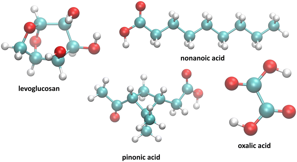 | ||
| Fig. 1 Set of molecules investigated in this work. | ||
The paper is organized as follows. Section 2 presents the force field used and the calculation of the surface tension and the free energy along a specific reaction coordinate. We discuss in section 3 the main results of this work from methodological and numerical viewpoints. Finally, in section 4, we draw the main conclusions of this study and potential atmospheric implications.
2 Computational details
2.1 Model
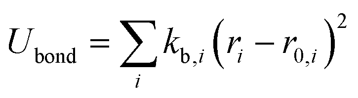
The OPLS-AA force field33–35 sums intramolecular and intermolecular energy contributions of a molecular system to yield the total configurational energy. The intramolecular interactions consist of bond stretching, angle bending, and dihedral and non-bonded energy contributions as described in eqn (1).| Uintra = Ubond + Uangle + Utorsion + Unb | (1) |
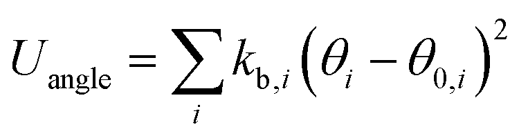
The bond stretching and angle bending energy are described by harmonic potentials defined by eqn (2) and (3), respectively.
 | (2) |
 | (3) |
In these equations, kb and kθ are the force constants and r0 and θ0 are equilibrium bond and angle values, respectively. The torsional energy is given by
 | (4) |
The non-bonded interactions between atoms of different molecules give rise to intermolecular interactions and non-bonded interactions occurring between atoms in the same molecule separated by more than three bonds are defined as intramolecular interactions. The specific 1,4-non-bonded intramolecular interactions are scaled by 0.5. These non-bonded interactions sum dispersion–repulsion and electrostatic contributions.
The electrostatic interactions between two charges qi and qj at a distance rij is represented by the Coulomb potential as
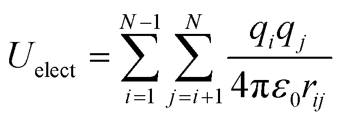 | (5) |
Van der Waals interactions are mostly described by the 12-6 Lennard-Jones (LJ) potential as
 | (6) |
The water molecules were modelled by using the SPC/E model.38 The association of the OPLS-AA model with the SPC/E water model has already been investigated on the free energy of solvation of organic molecules.39 Agreement with experimental data was also quantitatively demonstrated.39 Additionally, the SPC/E model was found to reproduce accurately the surface tension of water.40,41 The LJ parameters for the interactions between unlike sites were calculated by using the Good–Hope combining rules42,43 which are geometric for εij = (εijεjj)1/2 and σij = (σiiσjj)1/2 to be in line with the original version of the OPLS-AA model.33
The parametrizations of the selected solute molecules of Fig. 1 defining kb, kθ, r0, θ0, V1, V2, V3, V4, qi, εij and σij for each type of interaction are provided by the web-based automatic parameter generators, LigParGen.44 The partial charges are also provided by LigParGen using the 1.14*CM1A-LBCC method.45
2.2 Molecular dynamics
Molecular dynamics simulations were performed by using the LAMMPS package.46 In all the simulations, the periodic boundary conditions were applied in all three directions. In order to control the temperature, a Nosé–Hoover thermostat was applied47,48 and the temperature was always set to 290 K to mimic the temperature in the atmosphere.10 The cut-off distance for van der Waals interactions is set to rc = 12.0 Å, while the particle–particle particle mesh (PPPM) method with an accuracy of 1.0 × 10⁻⁴ and a cut-off of 12 Å is considered for the long-range electrostatic interactions. The velocity Verlet integrator was used to integrate the equations of motion using a reduced time step of 1 fs. Each system was first equilibrated as a bulk phase in the NPT statistical ensemble,49 setting a pressure of 1 atm for 100 ps. This is achieved by combining the hydrostatic equations of Martyna et al.50 with the strain energy proposed by Parrinello and Rahman.51 Then, vacuum was added on both sides along z for 10 ns; the dimensions of the cell were set to Lx = Ly = 50 Å while Lz = 150 Å. The acquisition phase was 20 ns long; the configurations were recorded every 20 ps.2.3 Potential of mean force and umbrella sampling (US)
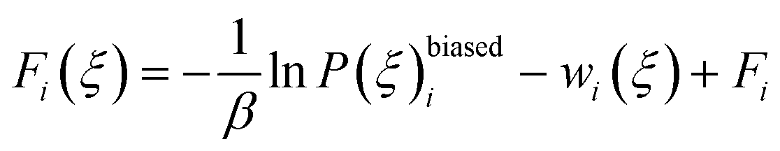
The potential of mean force (PMF)52 also called the free energy profile F(ξ) can be defined as the reversible work to be supplied to two particles which are infinitely-separated to bring them to a contact separation distance. F(ξ) is related to the probability density function P(ξ) of the reaction coordinate ξ as | (7) |
The probability density function P(ξ) is expressed as
 | (8) |
The Dirac delta function δ(ξ(rN) − ξ) means that we are effectively integrating over all coordinates r such that ξ(rN) = ξ. ξ(rN) is a vector-valued function of the Cartesian coordinates describing the degrees of freedom of interest.
In the umbrella sampling (US) formalism,53 a biasing potential wi(ξ) is added to the Hamiltonian to guide the simulations along a defined reaction coordinate toward a reference ξrefi. The calculation is then organized in a series of simulations with different points or windows. The biasing potential takes the form of a harmonic function of strength K to ensure sampling in all regions of ξ. Its operational expression is given by
 | (9) |
The total biased energy then sums ![[scr U, script letter U]](https://www.rsc.org/images/entities/char_e534.gif) (rN) and wi(ξ). The biased distribution function P(ξ)biasedi of the ith window is given by
(rN) and wi(ξ). The biased distribution function P(ξ)biasedi of the ith window is given by
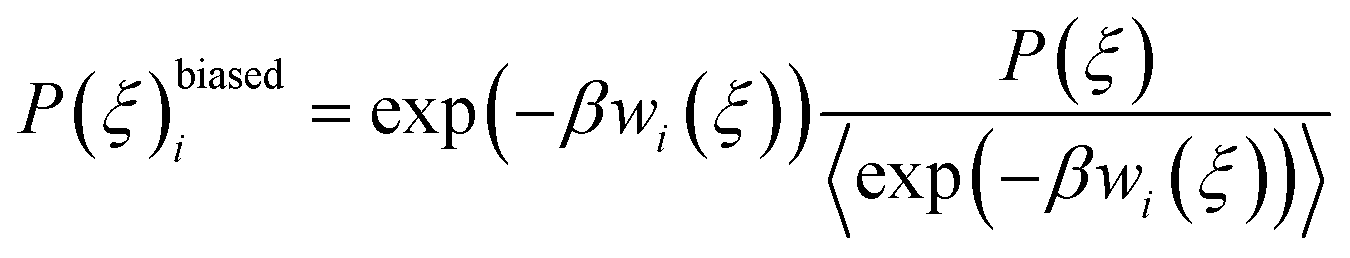 | (10) |
 | (11) |
| exp(βFi) = 〈exp(βwi(ξ))〉 | (12) |
2.4 Surface tension
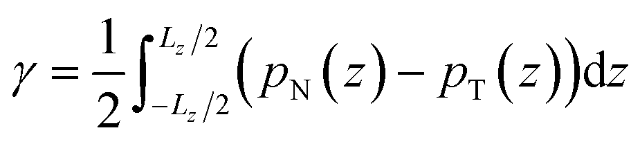
The surface tension γ, originally given by Kirkwood and Buff,56 is defined by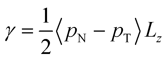 | (13) |
 . This expression gives a scalar but does not verify that the system is in mechanical equilibrium.
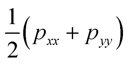
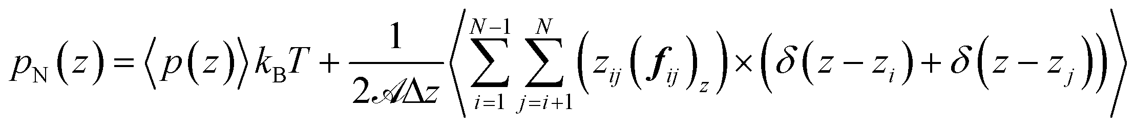
Irving and Kirkwood56–61 have shown that γ can be calculated from pN(z) and pT(z), the components of the pressure tensor as a function of z:
 | (14) |
 | (15) |
![[scr A, script letter A]](https://www.rsc.org/images/entities/char_e520.gif) is the surface area, Δz is the thickness of the slab and ρ(z) is the local number density. The simulation box is divided into Nz slabs of thickness δz. fij is the force between atoms i and j defined as:
is the surface area, Δz is the thickness of the slab and ρ(z) is the local number density. The simulation box is divided into Nz slabs of thickness δz. fij is the force between atoms i and j defined as: | (16) |
represents all the intramolecular and intermolecular energy contributions. The tangential component of the pressure tensor is then expressed as follows: | (17) |
These equations indicate that half of the virial contributions arising between atom i and atom j are assigned to the slab where i is located and the other half to the slab where j is located.
Eqn (13) and (14) should lead to the same value of γ. Indeed, we observe that the two definitions lead to maximum deviations of 0.3 mN m−1 which are within the statistical uncertainties of the simulation. Since we used a truncated spherical LJ potential, we need to apply a long-range correction to the surface tension called here γLRC and expressed as63
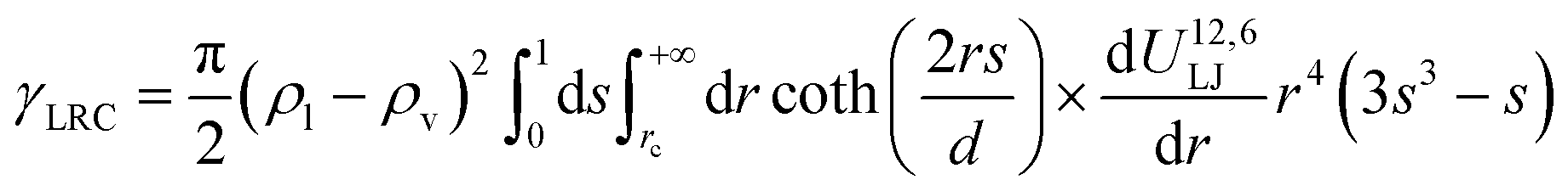 | (18) |
 | (19) |
By using the SPCE model for water,38 we found that the tail correction to the surface tension was equal to 3.9 mN m−1.
3 Results and discussion
3.1 Specific arrangements at the interface
In order to describe the water–air interface, we propose to plot in Fig. 2 the density profiles of water and organic molecules in the direction normal to the water surface at T = 290 K. We also add the atomic density profiles of oxygen atoms of the organic molecules. These simulations consider a total of 10 organic molecules for the simulation cell. We focus on only one interface for the sake of simplicity. These profiles clearly show two types of behaviour at the interface: (i) an adsorption peak followed by homogeneous distribution in the bulk phase of water and (ii) an adsorption peak at the water surface with only a very small fraction of organic molecules in the water solution. | ||
| Fig. 2 Molecular density profiles of the liquid–vapor interface of water modified by the addition of 10 organic molecules such as (a) levoglucosan, (b) oxalic acid, (c) nonanoic acid and (d) cis-pinonic acid. The density profiles of the organic molecules are read on the right-hand axis. The profiles were calculated as a function of the reduced position z* defined by z/Lz in the direction normal to the interface. One of both interfaces is shown for clarity. The dotted lines refer to the density profiles of the oxygen atoms of the organic molecules and should be read on the right-hand axis. | ||
More specifically, oxalic acid and levoglucosan molecules dissolve in water with a slight predominance at the interface. The presence of a slight peak of adsorption indicates that the organic molecules begin their hydration process before gradually entering the water bulk phase.64 Concerning the oxalic acid, the density profiles contrast with those obtained at lower temperatures26 ranging from 200 to 240 K. Actually, at these low temperatures, the density profiles exhibit only an adsorption layer of oxalic molecules at the ice surface while still suggesting a broadening of this layer as the temperature is increasing. It means that the desorption process has already started at 240 K, leading to the presence of a much less pronounced layer at 290 K with a majority of oxalic molecules dissolved in the bulk water. The analysis of the atomic profiles of oxygen atoms provides insight about the structure of the molecule. Indeed, for hydrophilic molecules such as levoglucosan and oxalic acid, the hydrophilic parts are distributed on both sides of the molecule's skeleton, which explains why the peak of adsorption of the oxygen atoms is not shifted in relation to that of the molecule.
In contrast, nonanoic and cis-pinonic acids are partitioned to the surface and form a kind of hydrophobic coating at the surface with only a tiny fraction of these molecules which sample the region of the bulk water phase. The density profiles of Fig. 2 show two well-separated phases as observed for the oxalic acid at lower temperatures.26 For the nonanoic acid, the hydrophilic part is at one end of the carbon chain. By comparing the peak of adsorption of oxygen atoms with that of the whole molecule, we deduce that the oxygen atoms are positioned in the interfacial region whereas the vapor phase is occupied by the carbon chains.
3.2 Free energy at the interface
In order to characterize the adsorption process of organic molecules on the water surface, we calculate the free energy profiles, also called potential of mean force (PMF), of these organic molecules as a function of the z-position along the direction normal to the interface. These profiles, calculated with the umbrella sampling (US) method, are shown in Fig. 3 for T = 290 K and represent the change of the free energy ΔF(z) when one organic molecule is moving from the vapor to the bulk water phases. ΔF(z) = 0 in the vapor phase as the organic molecules do not interact with any water molecules. These free energy profiles confirm the specific arrangements observed from the density profiles. Indeed, the propensity of nonanoic and cis-pinonic acids to adsorb at the water surface is confirmed by the negative free minima of ΔF(z) at the water–air interface, whereas oxalic acid and levoglucosan molecules exhibit only very shallow wells in line with hydrophilic molecules which prefer to stay in water bulk phases. We report in Table 1 the ΔFwater-int. property which is defined as the free energy gain of moving the molecule from water to the interface. This property ranges from −21.8 to −1.9 kJ mol−1. The organic molecules adsorb preferentially at the interface by forming an organic layer when ΔFwater-int. is at least equal to −11.5 kJ mol−1. For values higher than −4.1 kJ mol−1, we observe that the organic molecules are not involved in the hydrophobic adsorption layer. We also report for comparison in Table 1 the polarity index (PI),65 defined as the ratio between the number of oxygen atoms and carbon atoms of the molecule. Interestingly, only the two smallest PI values give significant free energy minima at the surface of water. | ||
| Fig. 3 Free energy profiles ΔF(z) calculated at T = 290 K for one organic molecule sampling the region from the vapor phase (high z) to the bulk water phase (low z). These profiles were calculated by using the umbrella sampling formalism and refer to the case of infinitely dilute solution. | ||
| ΔFwater-int. | ΔFint.-gas | ΔFPMFsolv. | ΔFexp.,calcsolv. | ΔFpHsolv. | PI | l ads | |
|---|---|---|---|---|---|---|---|
| (kJ mol−1) | (kJ mol−1) | (kJ mol−1) | (kJ mol−1) | (kJ mol−1) | (nm) | ||
| Levoglucosan | −1.9 | 54.0 | −52.1 | [−80.4, −64.1] | 0.83 | 0.35(5) | |
| Oxalic acid | −4.1 | 56.6 | −52.5 | [−81.3, −38.7] | 47.6 | 2 | 1.4(2) |
| Nonanoic acid | −21.8 | 36.9 | −15.1 | [−29.7, −22.1] | 11.7 | 0.22 | 3.4(4) × 103 |
| Cis-pinonic acid | −11.5 | 69.7 | −58.2 | −49.6 | 10.4 | 0.33 | 44(3) |
| Nonanoic + levoglucosan | −5.1 | 60.7 | 5.0(20) |
The ΔFint.-gas property listed in Table 1 reflects the free energy cost of transferring the organic molecule from the interface to the vapor phase. As expected by the nature of the interactions involved, we observe that this free energy contribution is unfavorable for all the organic molecules studied here, indicating that these molecules prefer either to remain at the interface or to dissolve in the water phase. In addition, nonanoic acid which presents the smaller PI index also yields the smaller ΔFint.-gas free energy contribution. From ΔFwater-int. and ΔFint.-gas, it is possible to deduce the free energy of solvation ΔFPMFsolv. which then corresponds to the transfer of one molecule from the vapor phase to the liquid phase. The ΔFPMFsolv. values are collected in Table 1. The free energy of solvation, whether experimental or calculated, can be defined through the Henry's constant KH as
ΔFexp.,calc.solv. = −RT![[thin space (1/6-em)]](https://www.rsc.org/images/entities/char_2009.gif) lnRTKH lnRTKH | (20) |
For a mono-acid, KH is expressed as
 | (21) |
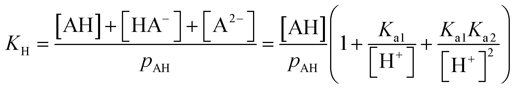 | (22) |
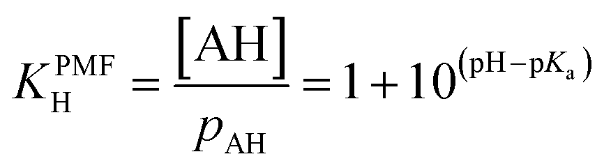 | (23) |
| = 1 + 10(pH−pKa1) + 10(2pH−pKa1−pKa2) | (24) |
| ΔFPMFsolv. = ΔFexp.,calc.solv. + RTlnKPMFH = ΔFexp.,calc.solv. + ΔFpHsolv. | (25) |
The temperature dependence of the free energy of solvation is evaluated through the dlnKH/d(1/T) quantity. When this quantity is equal to 9800 for oxalic acid,66 this indicates that the variation in the free energy of solvation ΔF298Ksolv. − ΔF290Ksolv. is about +2.8 kJ mol−1. Henry's constant quantifies how the solute is distributed among the bulk liquid water and the bulk vapor.
Given the variety of experimental and predicted Henry's law constant, the possible correction due to the acidity of the solution (see ΔFpHsolv. in Table 1) and the impact of temperature, we observe that the simulated free energy of solvation of the organic molecules agree qualitatively with literature data.
The liquid–vapor interface systems are formed by two components: the chemical substance 1 is water and the substance 2 is the solute defined by the organic molecules. In order to quantify how the solute is distributed among the surface and the bulk liquid water, we can use the adsorption length, defined by
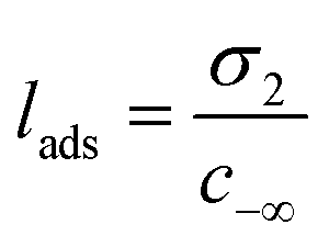 | (26) |
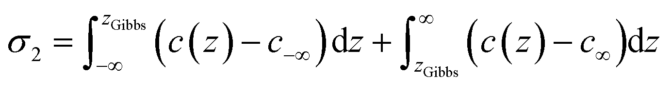 | (27) |
| c(z) = c∞e−ΔF(z)/RT | (28) |
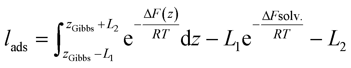 | (29) |
The values of lads are collected in Table 1. lads ranges from a few angstroms for the most hydrophilic species to a few micrometers for nonanoic acid. This means that most of the molecules of nonanoic acid will be confined to the surface for small droplets where the volume-to-surface ratio is less than or around a micrometer, whereas most of the molecules of levoglucosan or oxalic acid will stay in the bulk of the droplet. Indeed, the adsorption length represents the thickness of the bulk solution which contains as many solute molecules as the surface. cis-Pinonic acid has an intermediate adsorption length.
In the case of our LV system of two components, the Gibbs adsorption isotherm70 can be written as
| −dγ = σ1dμ1 + σ2dμ2 | (30) |
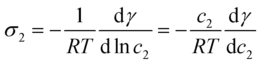 | (31) |
At infinite dilutions or low activities, lads is assumed to be constant. By using c2 = c−∞ = σ2/lads, the derivative of the surface tension γ with respect to the surface excess σ2 of the component 2 is simplified as
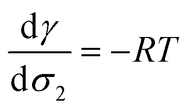 | (32) |
From a free energy per unit area viewpoint, Fig. 4 illustrates the dependence of the surface tension of water as a function of the surface excess of organic molecules at 290 K. The values of surface tension are listed in Table 2 along with the amount of added organic molecules and surface excess σ2. We also plot for comparison the  slope of eqn (32) which is equal to 0.16 mN m−1 per molecule. We restrict the curve γ = f(σ2) to 10 added molecules for each interface in order to respect the assumption of infinitely dilute solutions used to develop the Gibbs adsorption isotherm of eqn (31). First, the surface tension of water at 290 K compares very well with the value calculated from the thermodynamic definition71 at 298 K using the same model with a deviation less than 1%. The impact of temperature ΔT = 10 K is around 1.5 mN m−1 which remains within the uncertainties of the calculation.71
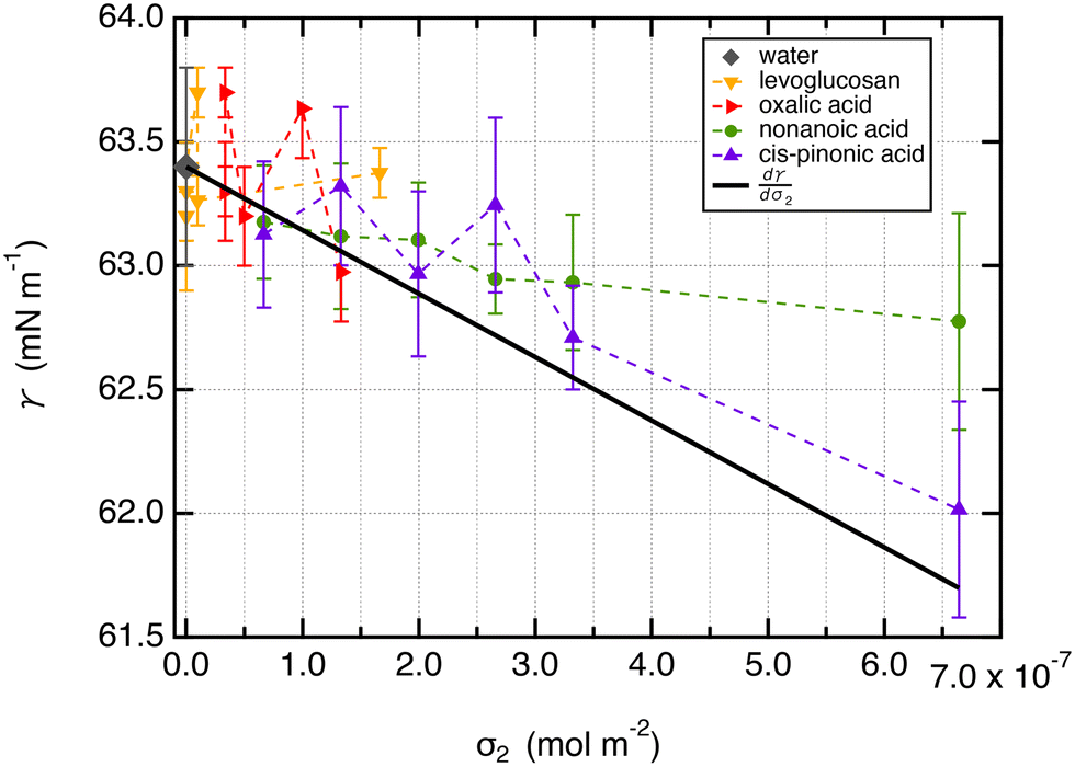 | ||
Fig. 4 Surface tension values (mN m−1) of liquid–vapor interfaces of water as a function of the surface excess of organic molecules (σ2) calculated at 290 K. The surface excess corresponds to a maximum of 10 adsorbed molecules to respect the hypothesis of infinitely dilute solutions. The slope  is equal to −2411 J mol−1 or 0.16 mN m−1 per molecule. The calculations were performed over 5 replicates to consider the statistical fluctuations as accurately as possible. is equal to −2411 J mol−1 or 0.16 mN m−1 per molecule. The calculations were performed over 5 replicates to consider the statistical fluctuations as accurately as possible. | ||
| n | σ 2 | γ | σ 2 | γ | σ 2 | γ | σ 2 | γ |
|---|---|---|---|---|---|---|---|---|
| (mol m−2) | (mN m−1) | (mol m−2) | (mN m−1) | (mol m−2) | (mN m−1) | (mol m−2) | (mN m−1) | |
| Nonanoic acid | cis-Pinonic acid | Levuglucosan | Oxalic acid | |||||
| 1 | 6.6 × 10⁻⁸ | 63.2(2) | 6.6 × 10⁻⁸ | 63.1(3) | 0 | 63.2(3) | 3.3 × 10⁻⁸ | 63.3(3) |
| 2 | 1.3 × 10⁻⁷ | 63.1(3) | 1.3 × 10⁻⁷ | 63.3(3) | 0 | 63.3(2) | 3.3 × 10⁻⁸ | 63.3(1) |
| 3 | 2.0 × 10⁻⁷ | 63.1(2) | 2.0 × 10⁻⁷ | 63.0(3) | 0 | 63.4(1) | 3.3 × 10⁻⁸ | 63.7(1) |
| 4 | 2.6 × 10⁻⁷ | 62.9(1) | 2.6 × 10⁻⁷ | 63.2(3) | 9.7 × 10⁻⁹ | 63.7(1) | 5.0 × 10⁻⁸ | 63.2(1) |
| 5 | 3.3 × 10⁻⁷ | 62.9(3) | 3.3 × 10⁻⁷ | 62.7(2) | 9.7 × 10⁻⁹ | 63.3(1) | 1.0 × 10⁻⁷ | 63.6(1) |
| 10 | 6.6 × 10⁻⁷ | 62.8(4) | 6.6 × 10⁻⁷ | 62.0(4) | 1.7 × 10⁻⁷ | 63.4(1) | 1.3 × 10⁻⁷ | 63.0(2) |
| 20 | 1.3 × 10⁻⁶ | 62.8(4) | 1.3 × 10⁻⁶ | 61.1(4) | 2.0 × 10⁻⁷ | 63.2(2) | 3.3 × 10⁻⁷ | 62.9(1) |
| 40 | 2.6 × 10⁻⁶ | 63.6(3) | 2.6 × 10⁻⁶ | 59.6(5) | 4.0 × 10⁻⁷ | 63.7(3) | 6.0 × 10⁻⁷ | 63.4(2) |
| Water | ||||||||
| γ = 63.4(4) mN m−1 | ||||||||
Second, for cis-pinonic and nonanoic acid molecules which show significant positive surface excess values, Fig. 4 shows that the surface tension decreases with the surface excess as expected from the Gibbs equation. The simulated surface tension of water with cis-pinonic acid molecules reproduces very well the theoretical slope. For nonanoic acid, a decrease of surface tension with respect to σ2 is observed, but the agreement with the theoretical prediction is less quantitative especially for the largest surface excess. Let us recall that the slope corresponds to only 1.6 mN m−1 for 10 added molecules at an interface with an area of 50 Å × 50 Å. This result agrees with previous simulations carried out on a water droplet10 which predict a decrease of 1.3 mN m−1 for 10 added cis-pinonic acid molecules. This weak decrease of surface tension over the 1–10 range of added molecules is at the limit of the accuracy of the methodology used for the calculation of γ even if γ was calculated over several replicates.
For levoglucosan and oxalic acid molecules, all added molecules dissolve in water and a few remain at the interface. We estimated the number of molecules at the surface of water from the integration of the density profiles in the interfacial region and then calculated the surface excess. By reporting the surface tension as a function of the surface excess, we observe that the surface tension does not change over this range of σ2 values within the statistical fluctuations.
Now, it is interesting to analyse the evolution of the surface tension in light of that of the hydrogen bonds in the system. Fig. 5a shows the number of hydrogen bonds between water molecules as a function of the position to the interface. First, we do not observe significant changes in the profiles of hydrogen bonds between pure water and systems with small surface excess values. We show for illustration in Fig. 5a the profile of hydrogen bonds with 5 oxalic acid molecules which matches very well with that of pure water. This is in line with a surface tension that has not changed over this range of σ2. When the amount of molecules added is greater, e.g. 40, the profiles of hydrogen bonds72 between water molecules are dependent on the organic molecule. If we pay attention to the only organic molecule which leads to a decrease of the surface tension, i.e. the cis-pinonic and nonanoic acid molecules, we observe that the hydrogen bond profiles have features different from other profiles, namely, a significant smaller number of hydrogen bonds on the liquid side of the interfacial region and a larger number of hydrogen bonds on the vapor side of the liquid–vapor interface. For these acids, the thickness of the interface has been significantly increased compared to oxalic acid and levoglucosan molecules. Fig. 5b shows the profiles of hydrogen bonds between all the species per bin. By summing all the possible hydrogen bonds, this figure supports the conclusions drawn from Fig. 5a and further establishes that the width of the interface has been increased with the cis-pinonic acid and to a lesser extent with the nonanoic acid. This increase of the interfacial thickness is in line with a decrease of the surface tension as reported by the van der Waals theory of surface tension.72 The explanation of the drop in surface tension with the number of cis-pinonic acid molecules is more complex than it seems and cannot be explained only by the reduction in the number of hydrogen bonds between water molecules as suggested by previous studies.10
 | ||
| Fig. 5 (a) Profiles of hydrogen bonds between water molecules as a function of the position from the interface. The z-positions were scaled so that the position of the Gibbs dividing surface is located at z = 0 for the interface of the right-hand side. The criteria used to select a hydrogen bond have been taken from ref. 73. Two water molecules are chosen as being hydrogen bonded only if the distance (O–H⋯O) between the donor and the acceptor is less than 2.5 Å and simultaneously the angle O–H⋯O is greater than 150°. (b) Number of total hydrogen bonds involving water–water, water–organic and organic–organic molecules per bin. The bin thickness is 0.3 Å. We used the same criteria of distance and angle. | ||
3.3 Hydrophobic layer of nonanoic acid
We now focus on the adsorption of levoglucosan on a layer of nonanoic acid molecules at the surface of water. To do so, we calculate the potential of mean force (PMF) of one molecule of levoglucosan on a monolayer of 40 nonanoic molecules. This free energy profile is shown in Fig. 6 along with the profile of levoglucosan calculated at the surface of pure water. Interestingly, we observe a deeper well depth at the surface as it is saturated with nonanoic acid. Indeed, the well depth increases from −1.9 to −5.1 kJ mol−1 (see Table 1). | ||
| Fig. 6 Free energy profiles ΔF(z) calculated along the direction normal to the interface for one molecule of levoglucosan which migrates from the vapor to liquid phases. The dotted blue curve corresponds to the profile where the surface of water is saturated by 40 nonanoic acid molecules. The PMFs were calculated by using the US method. | ||
It means that the presence of nonanoic acid at the interface attracts also the levoglucosan molecules. This is also supported by the value of the adsorption length of levoglucosan which increases by one order of magnitude (from 0.35 to 5.0 nm in Table 1) in the presence of nonanoic acid. This study shows that the presence of some acids with a small PI index at the interface can help the adsorption of more hydrophilic molecules at the surface of water that would not be effective at the surface of pure water.
We complete this study by doing standard MD simulations of the surface of water when it is saturated with nonanoic acid molecules. In this case, we investigate a system of ten levuglucosan and 80 nonanoic acid molecules. A typical equilibrium configuration is given in Fig. 7. This configuration shows the formation of a layer of nonanoic acids with the oxygen atoms pointing towards the water phase and levoglucosan molecules that can sample both the interfacial region and the bulk water phase. The density profiles shown in Fig. 8 confirm the specific arrangements at the interface, namely a hydrophobic monolayer of nonanoic acids with oxygen atoms positioned more on the inside of the water and a more marked adsorption peak of levoglucosan, if we refer to the peak of Fig. 2a, which is accompanied by a smaller fraction of levoglucosan in the water phase.
 | ||
| Fig. 7 Snapshot of a typical configuration of a system formed by two interfaces each saturated with 40 nonanoic acid molecules. Ten levoglucosan molecules represented by van der Waals spheres are then added to the system. | ||
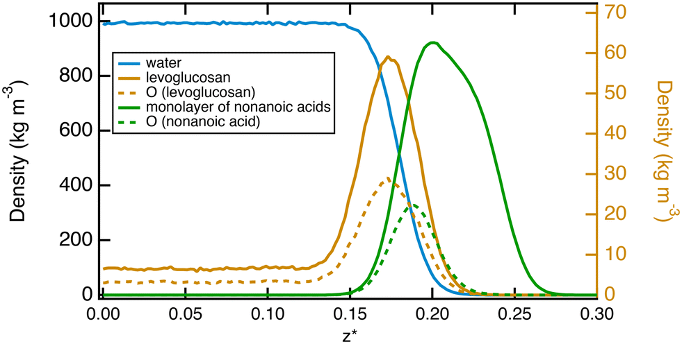 | ||
| Fig. 8 Density profiles as a function of the reduced z* position for water, levoglucosan and nonanoic acids as the surface of water is covered by 40 nonanoic molecules. The atomic profiles of oxygen atoms of levoglucosan and acid molecules are represented by dotted lines. The density profiles of levoglucosan and its oxygen atoms are read on the right-hand axis, while the other density profiles are read on the left-hand axis. | ||
4 Conclusions
The objective of this study was to provide a molecular-level understanding of the surface of water with different organic molecules detected in cloud waters and presenting contrasting polar and hydrophobic properties. We applied two-phase molecular simulations to investigate the structural and energetic properties of the liquid–vapor interface of water in the presence of levoglucosan and oxalic, nonanoic and cis-pinonic acids.The analysis of the molecular density profiles of levoglucosan and oxalic acid molecules at 290 K established that these molecules have a weak inclination for the interface while being dissolved in water. This relatively weak inclination for the water surface is also supported by the presence of shallow wells in the free energy profiles at the interface.
The nonanoic and cis-pinonic acid molecules preferred to accumulate on the surface of water. forming then a hydrophobic monolayer. The free energy profile calculated by moving the organic molecule from the gas phase to the center of the bulk water phase confirmed these specific arrangements from an energy viewpoint. Indeed, nonanoic and cis-pinonic acids exhibited free energy minima at the water surface of −21.8 and −11.5 kJ mol−1, respectively. We also observed that the surface tension of the liquid–vapor interface of water with these two acids decreases with respect to the surface excess of the solute as expected from the Gibbs adsorption isotherm. For levoglucosan and oxalic acid molecules, no dependence of the surface tension on the amount of organic molecules was underlined since these molecules dissolve in water. The profiles of the hydrogen bond of the cis-pinonic and nonanoic acids along the normal direction to the water surface differ from those of the levoglucosan and oxalic acid molecules.
We completed this study by focusing on a surface of water saturated by nonanoic acid molecules. The potential of the mean of a molecule of levoglucosan moving from the gas phase to the water by passing by the interfacial region established that the well depth of the free energy becomes deeper at the interface when it is covered with nonanoic acid molecules. These results confirmed the fact that the accumulation of organic molecules at the interface depends not only on the hydrophilic nature of the molecules but also on the composition of the interfacial region.
Molecular simulation is an effective tool for rationalizing the interfacial properties of water in the presence of organic molecules. This study also proposes to reconsider how a cloud chemistry model takes into account interfacial properties. Currently, those models consider only the reactivity of compounds in bulk phases and a kinetic parametrization of the mass transfer of molecules. They need to be better constrained to consider the presence of an organic film at the droplet surface and its effect on this mass transfer and the possible heterogeneous reactivity.
Author contributions
Julien Devémy: conceptualization, methodology, software, investigation, writing – original draft. Alain Dequidt: conceptualization, methodology, software, investigation, writing – review & editing. Pascal Renard: conceptualization, investigation, writing – original draft. Laurent Deguillaume: conceptualization, investigation, writing – review & editing. Patrice Malfreyt: conceptualization, methodology, writing – original draft, writing – review & editing.Conflicts of interest
There are no conflicts to declare.Acknowledgements
This work was granted access to the HPC resources of GENCI-IDRIS under the allocation 2022–2023 (AD010913369). The authors are grateful to the Mesocenter Clermont Auvergne University for providing computing and storage resources.Notes and references
- A. M. Deal, R. J. Rapf and V. Vaida, J. Phys. Chem. A, 2021, 125, 4929–4942 CrossRef CAS PubMed.
- J. S. Rowlinson and B. Widom, Molecular Theory of Capillarity, Clarendon Press, Oxford, 1982 Search PubMed.
- G. J. Gittens, J. Colloid Interface Sci., 1968, 30, 406–412 CrossRef.
- J. J. Jasper, J. Phys. Chem. Ref. Data, 1972, 1, 841–1009 CrossRef CAS.
- G. Vasquez, E. Alvarez and J. M. Navaza, J. Chem. Eng. Data, 1995, 40, 611–614 CrossRef.
- A. B. A. Bianco, L. Deguillaume, M. Vaïtilingom, E. Nicol, J.-L. Baray, N. Chaumerliac and M. Bridoux, Environ. Sci. Technol., 2018, 52, 10275–10285 CrossRef CAS PubMed.
- C. M. Salvador, T.-T. Ho, C. C.-K. Chou, M.-J. Chen, W.-R. Huang and S.-H. Huang, Atmos. Environ., 2016, 140, 565–575 CrossRef CAS.
- B. Nozière, M. Kalberer, M. Claeys, J. Allan, B. D'Anna, S. Decesari, E. Finessi, M. Glasius, I. Grgić, J. F. Hamilton, T. Hoffmann, Y. Iinuma, M. Jaoui, A. Kahnt, C. J. Kampf, I. Kourtchev, W. Maenhaut, N. Marsden, S. Saarikoski, J. Schnelle-Kreis, J. D. Surratt, S. Szidat, R. Szmigielski and A. Wisthaler, Chem. Rev., 2015, 115, 3919–3983 CrossRef PubMed.
- S. Hornik, J. Sykora, J. Schwarz and V. Zdimal, ACS Omega, 2020, 5, 22750–22758 CrossRef CAS PubMed.
- X. Li, T. Hede, Y. Tu, C. Leck and H. Agren, J. Phys. Chem. Lett., 2010, 1, 769–773 CrossRef CAS.
- K. A. Wokosin, E. L. Schell and J. A. Faust, Environ. Sci.: Atmos., 2022, 2, 775–828 Search PubMed.
- J. Reid, T. Eck, S. Christopher, R. Koppmann, O. Dubovik, D. Eleuterio, B. Holben, E. Reid and J. Zhang, Atmos. Chem. Phys., 2005, 5, 827–849 CrossRef CAS.
- K. T. Valsaraj, G. J. Thoma, D. D. Reible and L. J. Thibodeaux, Atmos. Environ., Part A, 2010, 27, 203–210 CrossRef.
- S. Rossignol, L. Tinel, A. Bianco, M. Passananti, M. Brigante, D. J. Donaldson and C. George, Science, 2016, 353, 699–702 CrossRef CAS PubMed.
- M. F. Ruiz-Lopez, J. S. Francisco, M. T. C. Martins-Costa and J. M. Anglada, Nat. Rev. Chem., 2020, 4, 459–475 CrossRef CAS PubMed.
- M. T. C. Martins-Costa and M. F. Ruiz-López, J. Am. Chem. Soc., 2023, 145, 1400–1406 CrossRef CAS PubMed.
- N. Hayeck, I. Mussa, S. Perrier and C. George, ACS Earth Space Chem., 2020, 4(8), 1247–1253 CrossRef CAS.
- K. Valsaraj, G. Thoma, D. D. Reible and L. Thibodeaux, Atmos. Environ., 1993, 27, 203–210 CrossRef.
- W. Seidl, Atmos. Environ., 2000, 34, 4917–4932 CrossRef CAS.
- S. E. Schwartz, in Chemistry of multiphase atmospheric systems, Springer, Berlin, Heildelberg, 1986, pp. 415–471 Search PubMed.
- M.-C. G. Chalbot, J. Brown, P. Chitranshi, G. Gamboa Da Costa, E. D. Pollock and I. G. Kavouras, Atmos. Chem. Phys., 2014, 14, 6075–6088 CrossRef PubMed.
- G. Engling, P. Herckes, S. Kreidenweis and J. Collett Jr., Atmos. Environ., 2006, 40, 2959–2972 CrossRef CAS.
- S. Enami, M. R. Hoffmann and A. J. Colussi, J. Phys. Chem. Lett., 2017, 8, 3888–3894 CrossRef CAS PubMed.
- G.-L. Hou, J. Zhang, M. Valiev and X.-B. Wang, Phys. Chem. Chem. Phys., 2017, 19, 10676–10684 RSC.
- X. Huang, J. Zhang, B. Luo, J. Luo, W. Zhang and Z. Rao, Atmos. Environ., 2019, 198, 133–141 CrossRef CAS.
- M. Darvas, S. Picaud and P. Jedlovszky, Phys. Chem. Chem. Phys., 2011, 13, 19830–19839 RSC.
- M. Darvas, S. Picaud and P. Jedlovszky, ChemPhysChem, 2010, 11, 3971–3979 CrossRef CAS PubMed.
- M. Luo, N. A. Wauer, K. J. Angle, A. C. Dommer, M. Song, C. M. Nowak, R. E. Amaro and V. H. Grassian, Chem. Sci., 2020, 11, 10647–10656 RSC.
- F. Goujon, P. Malfreyt, A. Boutin and A. H. Fuchs, Mol. Simul., 2001, 27, 99–114 CrossRef CAS.
- A. Ghoufi and P. Malfreyt, J. Chem. Phys., 2012, 136, 024104 CrossRef CAS PubMed.
- A. Ghoufi, P. Malfreyt and D. J. Tildesley, Chem. Soc. Rev., 2016, 45, 1387–1409 RSC.
- P. Renard, J. Devémy, A. Dequidt, P. Malfreyt and L. Deguillaume, in preparation.
- W. L. Jorgensen, D. S. Maxwell and J. Tirado-Rives, J. Am. Chem. Soc., 1996, 118, 11225–11236 CrossRef CAS.
- W. L. Jorgensen and J. Tirado-Rives, Proc. Natl. Acad. Sci. U. S. A., 2005, 102, 6665–6670 CrossRef CAS PubMed.
- M. Robertson, J. Tirado-Rives and W. Jorgensen, J. Chem. Theory Comput., 2015, 11, 3499–3509 CrossRef CAS PubMed.
- P. P. Ewald, Ann. Phys., 1921, 369, 253–287 CrossRef.
- J. W. Eastwood, R. W. Hockney and D. N. Lawrence, Comput. Phys. Commun., 1980, 19, 215–261 CrossRef CAS.
- H. J. C. Berendsen, J. R. Grigera and T. P. Straatsma, J. Phys. Chem., 1987, 91, 6269–6271 CrossRef CAS.
- D. Vassetti, M. Pagliai and P. Procacci, J. Chem. Theory Comput., 2019, 15, 1983–1995 CrossRef CAS PubMed.
- S. P. Kadaoluwa Pathirannahalage, N. Meftahi, A. Elbourne, A. C. Weiss, C. F. McConville, A. Padua, D. A. Winkler, M. Costa Gomes, T. L. Greaves and T. C. Le, et al. , J. Chem. Inf. Model., 2021, 61, 4521–4536 CrossRef CAS PubMed.
- P. Malfreyt, Mol. Simul., 2014, 40, 106–114 CrossRef CAS.
- H. A. Lorentz, Ann. Phys., 1881, 12, 127–136 CrossRef.
- D. Berthelot, C. R. Hebd. Seances Acad. Sci., 1898, 126, 1703–1855 Search PubMed.
- L. S. Dodda, I. Cabeza de Vaca, J. Tirado-Rives and W. L. Jorgensen, Nucleic Acids Res., 2017, 45, 331–336 CrossRef PubMed.
- L. S. Dodda, J. Z. Vilseck, J. Tirado-Rives and W. L. Jorgensen, J. Phys. Chem. B, 2017, 121, 3864–3870 CrossRef CAS PubMed.
- S. Plimpton, J. Comput. Phys., 1995, 117, 1–19 CrossRef CAS.
- S. Nosé, Mol. Phys., 1984, 52, 255–268 CrossRef.
- W. G. Hoover, Phys. Rev. A: At., Mol., Opt. Phys., 1985, 31, 1695 CrossRef PubMed.
- S. Melchionna, G. Ciccotti and B. Lee Holian, Mol. Phys., 1993, 78, 533–544 CrossRef CAS.
- G. J. Martyna, D. J. Tobias and M. L. Klein, J. Chem. Phys., 1994, 101, 4177–4189 CrossRef CAS.
- M. Parrinello and A. Rahman, J. Appl. Phys., 1981, 52, 7182–7190 CrossRef CAS.
- J. G. Kirkwood, J. Chem. Phys., 1935, 3, 300–313 CrossRef CAS.
- G. M. Torrie and J. P. Valleau, J. Comput. Phys., 1977, 23, 187–199 CrossRef.
- S. Kumar, J. M. Rosenberg, D. Bouzida, R. H. Swendsen and P. A. Kollman, J. Comput. Chem., 1992, 13, 1011–1021 CrossRef CAS.
- B. Roux, Comput. Phys. Commun., 1995, 91, 275–282 CrossRef CAS.
- J. G. Kirkwood and F. P. Buff, J. Chem. Phys., 1949, 17, 338–343 CrossRef CAS.
- J. H. Irving and J. Kirkwood, J. Chem. Phys., 1950, 18, 817–829 CrossRef CAS.
- J. S. Rowlinson and B. Widom, Molecular Theory of Capillarity, Clarendon Press, Oxford, 1982 Search PubMed.
- J. P. R. B. Walton, D. J. Tildesley, J. S. Rowlinson and J. R. Henderson, Mol. Phys., 1983, 48, 1357–1368 CrossRef CAS.
- J. P. R. B. Walton, D. J. Tildesley, J. S. Rowlinson and J. R. Henderson, Mol. Phys., 1983, 50, 1381 CrossRef.
- K. Shi, E. E. Santiso and K. E. Gubbins, J. Chem. Phys., 2021, 154, 084502 CrossRef CAS PubMed.
- A. Harasima, Advances in Chemical Physics, Wiley & Sons, 1958, pp. 203–237 Search PubMed.
- E. M. Blokhuis, D. Bedaux, C. D. Holcomb and J. A. Zollweg, Mol. Phys., 1995, 85, 665–669 CrossRef CAS.
- A. Ghoufi and P. Malfreyt, Phys. Chem. Chem. Phys., 2010, 12, 5203–5205 RSC.
- B. Xing, W. B. McGill and M. J. Dudas, Environ. Sci. Technol., 1994, 28, 1929–1933 CrossRef CAS PubMed.
- C. Qin, Y. Gou, Y. Wang, Y. Mao, H. Liao, Q. Wang and M. Xie, Atmos. Chem. Phys., 2021, 21, 12141–12153 CrossRef CAS.
- R. Sander, Atmos. Chem. Phys., 2023, 23, 10901–12440 CrossRef CAS.
- H. Lignell, S. A. Epstein, M. R. Marvin, D. Shemesh, B. Gerber and S. Nizkorodov, J. Phys. Chem. A, 2013, 117, 12930–12945 CrossRef CAS PubMed.
- H.-J. Butt, K. Graf and M. Kappl, Physics and Chemistry of Interfaces, John Wiley & Sons, 2003 Search PubMed.
- H.-J. Butt, K. Graf and M. Kappl, Physics and chemistry of interfaces, John Wiley & Sons, 2023 Search PubMed.
- C. Vega and E. de Miguel, J. Chem. Phys., 2007, 126, 154707 CrossRef CAS PubMed.
- R. Lovett, P. W. DeHaven, J. Vieceli, J. James and F. P. Buff, J. Chem. Phys., 1973, 58, 1880–1885 CrossRef CAS.
- A. Luzar and D. Chandler, Phys. Rev. Lett., 1996, 76, 928–931 CrossRef CAS PubMed.
| This journal is © The Royal Society of Chemistry 2024 |