
 Open Access Article
 This Open Access Article is licensed under a Creative Commons Attribution-Non Commercial 3.0 Unported Licence
Characterizing catalyst function and transformations in the plasma reduction of CO2 on atomic layer deposition-synthesized catalysts†
Samuel K.
Conlin
 a,
Hamed
Mehrabi
b,
David N.
Parette
a,
Eva M.
Nichols
c and
Robert H.
Coridan
*ab
a,
Hamed
Mehrabi
b,
David N.
Parette
a,
Eva M.
Nichols
c and
Robert H.
Coridan
*ab
aDepartment of Chemistry and Biochemistry, University of Arkansas, Fayetteville, AR 72701, USA. E-mail: rcoridan@uark.edu
bMaterials Science and Engineering Program, University of Arkansas, Fayetteville, AR 72701, USA
cDepartment of Chemistry, University of British Columbia, Vancouver, British Columbia V6T 1Z1, Canada
First published on 29th February 2024
Abstract
The enhancement of CO2 reduction in atmospheric-pressure, non-thermal plasma has been shown using a variety of catalyst systems with ranging composition, particle sizes, and morphologies. Improvements in CO2 conversion can be attained by choice of catalyst material. However, inhomogeneity in the material distribution arising from the synthesis affects the catalytically active surface area and dielectric environment that modulates the plasma properties near the catalyst. Atomic layer deposition (ALD) can be used to control the composition of ultra-thin layers on support materials. We used ALD to synthesize metal oxide catalyst coatings on high surface area supports. We found that TiO2 achieved significantly higher yields of CO2 conversion (to CO and O2) at low reactor power compared to ZnO or Al2O3, materials commonly used as a support for other catalysts. We also observed an unexpected increase in the catalytic activity on ZnO with increasing power. The results here suggest that ALD can unambiguously isolate the catalytic effects of materials in plasma reactors.
Introduction
The steady rise of atmospheric CO2 due to fossil fuel use has resulted in increasing global average temperatures.1–3 Due to environmental concerns and developing economic incentives, a number of technologies have been developed for transforming captured CO2 into more useful molecules as a feedstock for other chemical processes.4–7 One promising example is the use of non-thermal plasmas to convert CO2 into CO and O2, with the product CO of use to other industrial or synthetic applications.8–14 The dielectric barrier discharge (DBD) reactor is commonly used for this reaction, as it is relatively straightforward to construct and is capable of producing a non-thermal plasma with relatively high-energy electrons (1–10 eV) and low bulk gas temperatures.9,14–16 These high energy electrons are capable of directly splitting CO2 into CO and O2. Particulate heterogeneous catalysts composed of metal oxide materials such as ZnO, Al2O3, or multi-metal oxides are often packed inside the discharge region of the reactor to improve both conversion rates and efficiency.9,17,18 The catalyst material is commonly formed by distributing chemically-synthesized catalyst particles either as a packed bed or deposited onto an inert support material inside the plasma volume. Particles are generally deposited onto the support by capillary solvent adsorption or vapor deposition techniques.19–22 The structure of the support and catalyst has been shown to influence the overall CO2 conversion by affecting the true active catalytic surface area, the flow dynamics of reactant gases, and the electric field inside the discharge region.9,23–25 Specifically, the effects of macroscopic catalyst loading and morphology on plasma–catalyst interactions have been explored in other works. For example, increasing support packing density has been shown to affect the primary discharge mode of the reactor, decreasing the selectivity towards CO during plasma–catalytic dry reforming of methane (DRM).23–25 The morphology of the catalyst itself has also been shown to be important, with nanoparticle Ni dendrites and flakes on alumina support having been shown to be more active for plasma–catalytic DRM than identical weight loadings of Ni nanospheres.26 Clearly, to make direct comparisons of different catalysts for plasma CO2 reduction requires consideration of the synthesis and decoration method, even for identical chemical composition.While the use of particulate catalysts may allow for convenient control during synthesis, the heterogeneity of the distribution can have significant effects on the process. It is difficult to separate catalytic effects from those derived from mass transport or interactions with the plasma in the reactor. Atomic layer deposition (ALD) is a self-limiting, highly-controlled growth process that is capable of depositing conformal films with atomic control over layer thickness and composition.27–31 ALD has also been shown to be capable of conformally coating the nanopores of support materials without changing the overall porosity or microstructure of the support.32,33 This control, along with the low-pressure deposition environment, allows for the coating of high aspect ratio or geometrically complex features, such as microwires or foams, without the line of sight restrictions imposed by other coating techniques such as sputtering or flame-spray.34–37 ALD has been used to synthesize electrocatalysts or thermal catalysts on supports for CO2 reduction.38,39 With respect to plasma catalysis, ALD has primarily been used as a method for applying catalysts developed for pollutant degradation and non-oxidative methane coupling.38,40
In this work, we characterize the activity of ALD-synthesized thin films of metal oxide catalysts on an aluminosilicate support for catalyzing CO2 reduction in a DBD plasma reactor. This approach regularizes the structure of the support and isolates the catalytic effects of the nanoscale, conformal coating. We used ALD to prepare three metal oxide catalysts of interest for CO2 reduction in a DBD plasma reactor to produce CO and O2. TiO2 has been investigated as a plasma CO2 reduction catalyst, and is therefore a well-known catalyst around which to develop this technique.41–46 Al2O3 was chosen because it has been shown to be much less active for plasma CO2 reduction than other metal oxides and has often been used as a support material for other catalysts.9,17,47,48 ZnO is typically used in DBD plasma reactions as a support material for other co-catalysts such as Pd or Cu for CO2 hydrogenation reactions.38,49–51 While both TiO2 and Al2O3 behaved as expected, we observed a significant increase in the activity of ZnO with increasing reactor power. Regularizing the catalyst structure shows that this transition is only explained by a transition in the behavior between the ZnO surface and the plasma. There is significant catalytic behavior from a material that is conventionally considered a support material. More generally, this work shows that ALD can be used to isolate catalytic activity from other effects (mass transport, plasma variability near dielectric interfaces) in complex plasma reduction reactions.
Materials and methods
ALD catalyst preparation
The support used as a substrate for the deposition of catalysts was a commercial aluminum-silicate wool (Lynn Manufacturing, USA) designed to withstand high temperatures. The support was comprised of fibers that were roughly 5–8 μm in diameter as determined by optical microscopy and was used as received from the manufacturer. Sections of the support (1.010 g, 60 × 60 × 7 mm) were cut and cleaned using a successive solvent wash of acetone (99%, EMD Millipore Corp), methanol (HPLC grade, VWR Analytical), isopropanol (HPLC grade, VWR Analytical) and water (HPLC grade, VWR Analytical) respectively, all of which were used as received. Once cleaned, the supports were dried at 180 °C for 1 hour before a final treatment in a UV-ozone cleaner for 30 minutes. The supports were then used directly for preparing the ALD-synthesized catalysts.The ALD layers were grown in a commercial ALD reactor (GEMstar XT; Arradiance Inc.) by a sequence of exposures of an organometallic precursor and water as an oxygen source. The precursors were contained in a vial sealed with a metal gasket: trimethylaluminum (TMA, 98%; Strem, Inc.) for Al2O3, diethylzinc (DEZ, 95%; Strem, Inc.) for ZnO, and tetrakis(dimethylamido)titanium (TDMAT, 99%; Strem, Inc.) for TiO2. The specific details of each ALD cycle for the growth of these oxides are provided in the ESI.† Each heterogeneous catalyst was composed of an ALD-synthesized layer conformally coating the support. The ALD coatings began with a 50-cycle base layer of Al2O3 onto the support to provide a consistent interface between each catalyst and the support. The catalyst layer was deposited over this base layer: 200 cycles of TDMAT/H2O to prepare TiO2, 58 cycles of DEZ/H2O to prepare ZnO, or 93 additional cycles of TMA/H2O to prepare Al2O3. These layer structures were chosen to grow catalyst layers of sufficient thickness to behave like the bulk compound yet add negligible thickness to the fibers. After the deposition was completed, the samples were removed from the ALD reactor and annealed in air at 500 °C for three hours (after a 3 °C min−1 ramp from room temperature). This was done to remove any remaining unreacted precursor detritus left behind from the ALD process and to controllably carry out calcination of the films prior to plasma exposure, both of which would affect the activity of the catalysts.
Reactor configuration and operation
We developed the reactor setup shown in Fig. 1a and b to compare the performance of ALD-prepared plasma catalysts. The catalysts (ALD-coated fiber supports) were loaded into the plasma volume. This volume was established by the length of the exterior aluminum foil electrode (20 μm thick). The length of the exterior electrode was 55 mm and wrapped three times around the tube. It was connected to the transformer by a metal hose clamp which also acted to mechanically fix the electrode to the quartz tube (25 mm outer diameter). The catalyst was fixed in place by packing it between the inner stainless-steel electrode (15.8 mm outer diameter) and the quartz wall of the tube (1.6 mm thick). The radial discharge gap was fixed at roughly 3.0 mm between the interior electrode and dielectric barrier, both of which were cleaned and polished between samples. An AC signal (12–20 kV, 19 kHz) was provided between the interior and exterior electrodes by an AC transformer (Allanson SS1235OX). The input power provided to the transformer (denoted input power) was monitored by a power meter measuring the power into the transformer. The plasma input power could therefore be set using a variable autotransformer for each experiment to study the influence of plasma input power on CO2 conversion and catalyst stability. The reactor was not cooled during any experiments and thermal management was provided by controlling the plasma ‘on’ time, during which the exterior or the reactor never exceeded 250 °C (Fig. S1†). Input CO2 flow was provided by a mass flow controller (SmartTrak 50; Sierra). The reactor was continuously fed CO2 (Airgas 99.999%) at a rate of 75 sccm and maintained at 1 atm. The reactor gas passed through the discharge region, then into an on-line gas chromatograph (6180-GC; SRI) containing two 1.1 mL auto-sampling loops. One loop delivered a portion of the sample to a 2 m Hayesep-D column. The other sampling loop delivered the rest of the sample to a 1.82 m Molsieve-5 Å column with an attached 0.475 m Hayesep-D pre-column. Each of these samples were directed to a pair of in-line detectors: a flame ionization detector (FID) for detecting carbon-containing products and a thermal conductivity detector (TCD) for other products. The use of a Molsieve-5 Å column necessitated the use of a timed injection-backflow sequence to prevent column fouling with CO2. While this double injection scheme was capable of separating CO2, CO, and O2, it produced multiple signals for the same product, as well as introduced variation in the CO and O2 intensity depending on the sample path.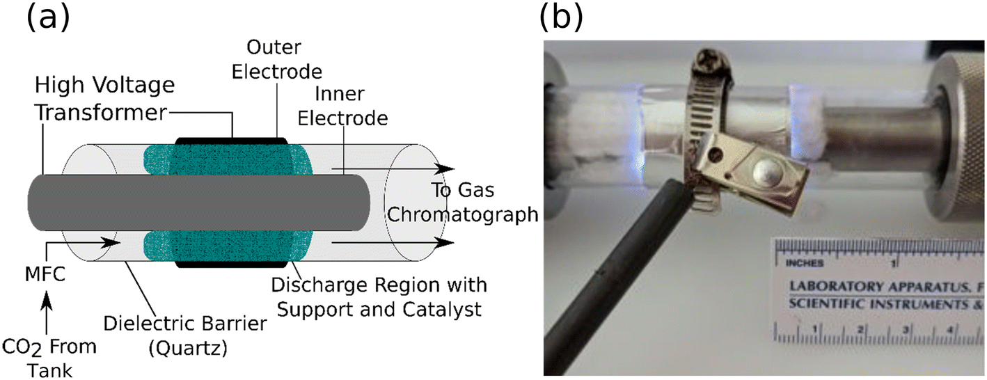 | ||
| Fig. 1 (a) A schematic of the DBD plasma reactor used to compare the catalytic activity of ALD-coated supports. The end caps of the reactor are omitted for clarity. (b) A photograph of the discharge region of the reactor during operation. | ||
The raw CO2 conversion yield, XCO2 (eqn (S1)†), was quantified by comparison to a measured calibration curve and used as the metric for catalytic activity. CO and O2 retention times were calibrated via a commercial calibration standard. Prior to each plasma catalysis experiment, null runs were performed with the catalyst in place but without the plasma to establish the baseline quantity of CO2 in the GC measurements (denoted CO2,in). The plasma input power was then set to a determined value during each experiment and the output gas of the reactor was sampled to measure the amount of unreacted CO2 in the exit stream (CO2,out). The raw CO2 conversion ratio, XCO2, was determined by the relative loss of CO2 during the experiment after accounting for the gas expansion for this isobaric reaction.52–54 The details of this correction are shown in the ESI† (eqn (S1)–(S4)). This process was repeated three times on fresh, as-prepared samples for each combination of catalyst material and reactor input power. The specific energy input (SEI) into the feedstock was defined by eqn (S3),† with the energy input varying by no more than 3% throughout the period of a single test. Each test consisted of a two-minute plasma-on period followed by a twenty-minute plasma-off and purge period. The isobaric-corrected CO2 conversion percent values, (fCO2), and the SEI were utilized to determine the input power conversion of the process as in eqn (S4).† The gas residence time in the discharge region was assumed to be the same for all packed reactor conditions due to the highly uniform nature of the catalyst/support pair and the consistent sample-to-sample packing density.
Imaging and spectral characterization
Scanning electron microscopy (SEM) imaging was performed using a FEI Nova NanoLab 200 SEM equipped with a field emission source and an energy-dispersive X-ray (EDX) spectrometer. X-ray photoelectron spectroscopy (XPS) measurements were taken with PHI Versaprobe Tetra.Optical microscopy was performed using an Olympus BX53M microscope under white light illumination. Thermal imaging was performed using a thermal camera (Shot-Pro, SEEK Thermal).
Results and discussion
Effect of ALD catalyst on CO2 conversion and reactor input power conversion efficiency
We measured the conversion percentage of CO2 resulting from a single pass through the discharge region of the DBD plasma reactor. The conversion ratio of each catalyst is shown in Fig. 2a as a function of input power. The conversion percentage of CO2 increased significantly as a function of input power for each tested catalyst. The trend of increasing CO2 conversion rate with increasing input power, regardless of catalyst, has been observed in previous work, and is typically attributed to both an increase in the frequency of micro-discharges and an increase in the average electron energy in the discharge gap.44,55,56 However, we observed a diminishing relationship between CO2 conversion rate and input power of the reactor in all cases. The conversion ratio and input power conversion efficiency in the empty reactor, as shown in Fig. 2b, was consistently lower than the reactor loaded with the bare support material or any of the tested catalyst at all input powers. While it is not possible to exclude the heterogeneous effects of the quartz tube surface, we used the empty tube measurements as the baseline for the direct, uncatalyzed plasma reaction process. It is also not possible to isolate surface interactions from the mass transport effects of the bare support. The difference in reactivity between the empty reactor and the bare support while the surface composition is practically the same (significantly SiO2) does indicate that there are non-catalytic effects of making the pathway through the reactor more tortuous. This is likely due to the characteristics of the plasma–support interactions and to the increased residence time of the gas in the plasma volume.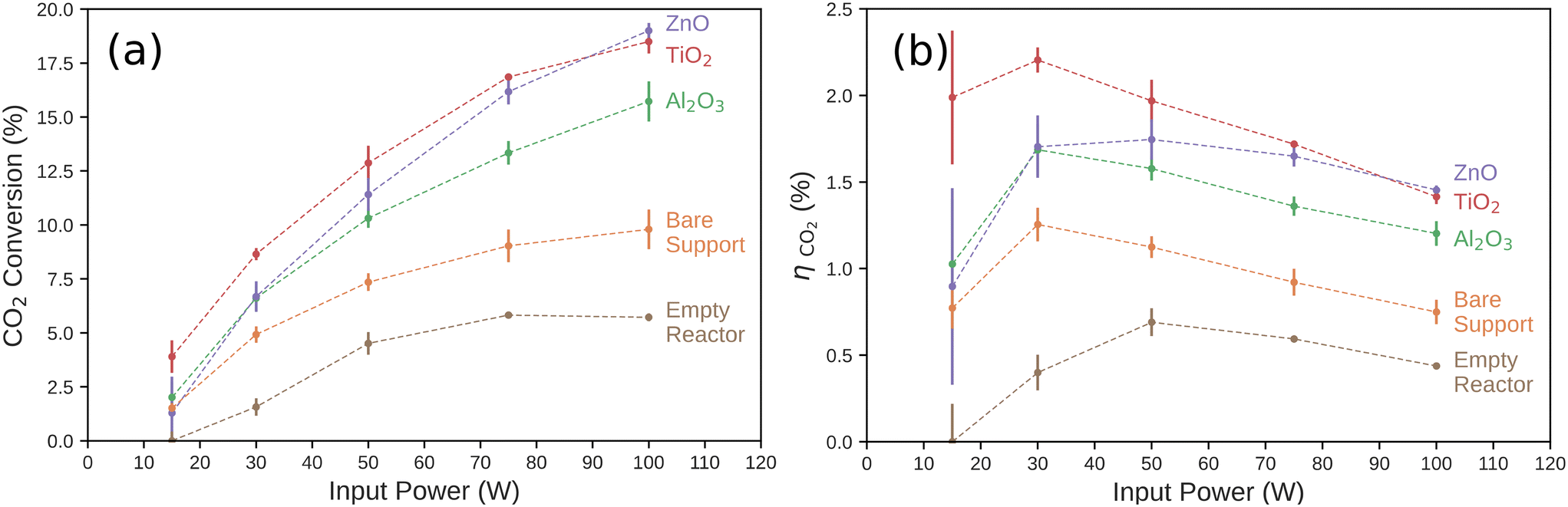 | ||
| Fig. 2 (a) CO2 conversion percentage and (b) the power conversion efficiency (ηCO2) for each catalyst as a function of input power to the DBD plasma reactor. The conversion percentage and error bars are calculated from experiments performed on three independent, identically prepared catalysts and show the range of the data collected. ηCO2 was computed from the CO2 conversion rate for each catalyst (Fig. 2a) and the Gibbs free energy of the CO oxidation reaction as described in eqn (S4).† | ||
We then compared the performance of catalytic effects of ultra-thin ALD films deposited on the support material. While the Al2O3 catalyst was the least active of the tested layers, it was more active than the bare support, especially at higher input powers. The TiO2 catalyst showed the highest conversion percentage across the input power range, with a 3.9% conversion rate at 15 W to an 18.5% conversion rate at 100 W. We observed a power dependence on the behavior of ZnO. At the lowest power measured (15 W), the ZnO catalyst performed worse than the bare support, though these were both within one standard deviation of each other and Al2O3. ZnO and Al2O3 were statistically equivalent at 30 W. At higher input power, the CO2 conversion percentage rose steeply with power compared to all other catalysts measured. At 100 W, ZnO gave the highest CO2 conversion percentage (19.0%) of any of the catalysts measured here. This is significant as ZnO has traditionally been utilized as a support for catalysts in both thermal- and non-thermal CO2 hydrogenation plasma reactions. ZnO has generally been shown to have negligible catalytic effect when used in DBD systems alone at low input powers. It is usually thought to contribute to these reactions by acting as a support for other metal catalysts and forming reduced ZnOx species near the catalyst–support interface.49,50,57
Another important metric for fuel-forming reactions, such as CO2 reduction to CO, is the input power conversion efficiency, ηCO2. This measures the ratio of the Gibbs free energy of combustion of the moles of CO2 converted to CO to the reactor input power. This is particularly important if the products are intended to be used as a fuel, for example. Here, the oxidation of CO(g) to CO2(g) is the reverse of the main reaction occurring in the plasma reactor. CO(g) formation has a Gibbs free energy of reaction of ΔG0rxn = −257.2 kJ mol−1, and this is the simplest reaction to consider as the chemical power output of the plasma reactor. Other reactions or methods for recouping the input power, such as use of the waste heat, are not considered here. As shown in Fig. 2b, the input power conversion efficiency of the CO2 reduction reaction generally decreased as input power increased. We observed a nearly linear decrease for input power conversion efficiency on the TiO2 catalyst with input power. Compared to the TiO2 catalysts, the other catalysts did not have comparable CO2 conversion ratios at low input power. The difference between the power conversion efficiency of the ZnO and TiO2 became insignificant at higher input powers. Also, the input power conversion efficiency on Al2O3 and the bare support all slightly increased at low input powers before also diminishing at higher input powers. These results suggest that the optimal operating input power of the reactor is dependent on the choice of metal oxide plasma catalyst.
We used a power law analysis to characterize the catalytic behavior of each of the catalyst materials. This empirical analysis is analogous to Tafel slope analysis of the potential-dependent performance of electrocatalysts and more sophisticated methods in plasma catalysis.58,59Fig. 3 shows the square of the fraction of CO2 conversion as a function of input power. TiO2, Al2O3, and the bare support all showed linear behavior in this plot, indicating a square-root dependence of CO2 conversion yield on the input power. The slopes of these lines may have some physical or kinetic relevance, but we can simply use them as a metric for catalytic performance. At low power (≤30 W in these experiments), ZnO follows the same slope as Al2O3, a known support material for catalysts, indicating low catalytic activity. The slope increases significantly at higher powers, yet remains linear and intersects the TiO2 line at 100 W. This suggests that the ZnO behavior is power dependent, switching from behaving as a support at low power to a catalyst at high powers. This may affect the interpretation of ZnO-supported catalytic behavior in other systems.
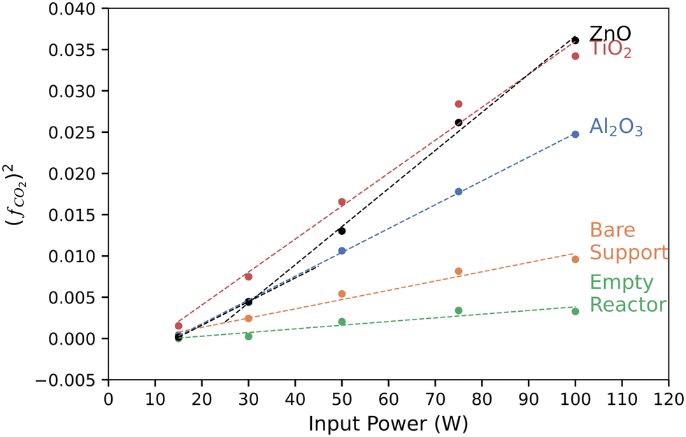 | ||
| Fig. 3 Squared yield of converted CO2, (fCO2)2, of each catalyst at a fixed CO2 flow rate of 75 sccm as a function of input power. (fCO2)2 was computed from eqn (S2).† | ||
We used optical microscopy to characterize the surface of the catalysts before and after plasma exposure. This helped to determine if any structural changes occurred during the experiments. As seen in Fig. 4, the support fibers appear unchanged after several minutes of plasma exposure, with no indication of melting or degradation. Small, optically opaque particles were observed on each of the catalysts after 30 minutes of plasma exposure. EDX spectroscopy of the particles and on regions away from the particles, Fig. 5, showed that the particles were composed of a significant amount of carbon. We attribute the Cu signal present in Fig. 5c to the conductive tape used to mount the sample to the stage. The substrate Cu signal was more intense due to the relatively lower electron-beam attenuation from the fiber compared to the spectrum measured in Fig. 5b. The EDX composite, Fig. 5b, also showed that the regions of the C deposition were mainly localized to the particles, and only adventitious carbon or very thin deposits were visible elsewhere on the fibers. The particles were approximately 1–3 μm in diameter and were observed more frequently at the intersections of support fibers or at irregularities in the fiber diameter. We observed that the amount of carbon deposition appeared to increase with increasing reactor input power. Qualitatively, greater deposition was visible via optical microscopy on catalysts exposed to 100 W of plasma input power than 50 W. The Al2O3 catalysts saw significantly more carbon deposits than either the TiO2 or ZnO catalysts. In some cases, the Al2O3 catalysts were visually darker in some regions due to the particle deposition, whereas negligible discoloration was observed on the TiO2- and ZnO-coated catalysts. Deposition of carbon species in DBD reactors due to the Boudouard reaction has been previously reported at the input powers and temperatures encountered during the experiments.19,60,61 Due to the gas-phase analysis used here, the direct splitting of CO2 to produce C(s) cannot be quantified. However, these observations suggest that a portion of the CO2 transformation activity on Al2O3 can be ascribed to coke formation. More generally, the deposition of carbon may vary with catalyst chemistry.12 Additionally, the CO2 transformation rates for each catalyst showed negligible differences as we repeated the power series measurements on a given catalyst. While some solid carbon could have deposited during this sequence, the negligible variation from the first power series measurement (fresh catalyst) to the third series (potential C deposition) suggests that any C(s) present does not influence the catalytic activity of the metal oxide layer.
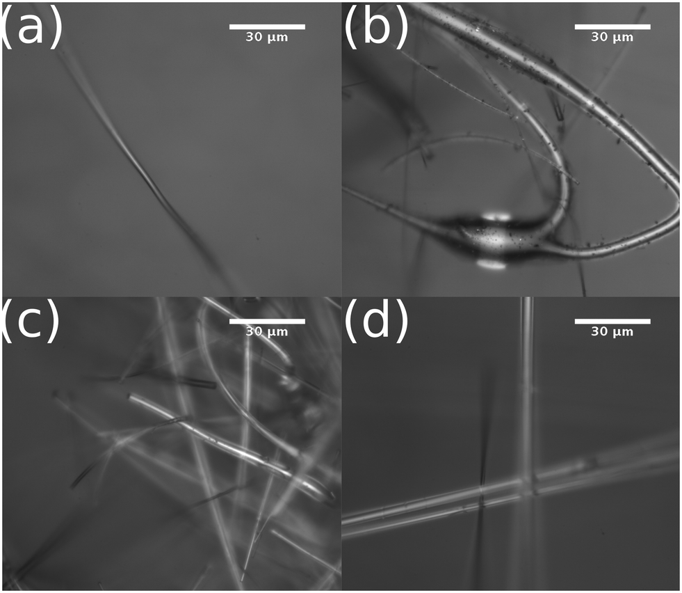 | ||
| Fig. 4 Optical microscopy of (a) an ALD-TiO2 coated support prior to plasma exposure, (b) an ALD-Al2O3 coated support after plasma catalysis, (c) an ALD-TiO2 coated support after plasma catalysis, and (d) an ALD-ZnO coated support after plasma catalysis. | ||
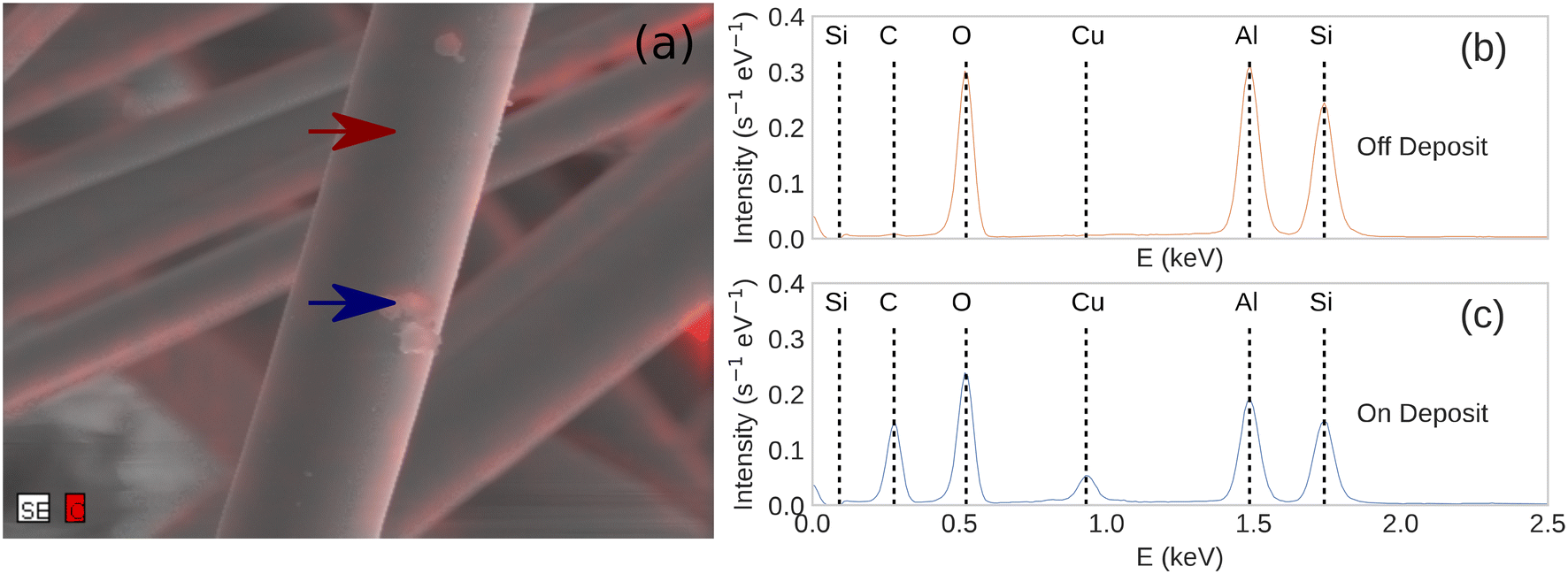 | ||
| Fig. 5 (a) An overlayed composite image of the secondary electron micrograph (grayscale) and the C EDX micrograph (red) of a post-reaction Al2O3 plasma catalyst. EDX spectra of an Al2O3 plasma catalyst after the reaction (b) on the supported catalyst away from any deposited particle and (c) on a particle deposited during the DBD plasma reaction. | ||
XPS is sensitive to the composition and oxidation state of an interface. We used XPS to characterize the surface of ALD-synthesized catalysts in both the as-prepared and post-plasma exposure states. This comparison allowed us to measure any transformations or degradation of the catalyst during the plasma CO2 reduction process. All ex situ samples were left in the air for at least 1 day prior to XPS characterization. The TiO2 catalyst showed intensity at binding energies of 458.2 eV and 464 eV corresponding to the Ti 2p3/2 and the 2p1/2 features, respectively, consistent with the Ti4+ in TiO2 (Fig. 6a).44,62 After plasma exposure, we observed the same features. Additionally, we observed the formation of a new feature in these XPS regions at binding energies of 456.2 eV and 461 eV, consistent with formation of reduced Ti3+ species as shown in other plasma-reduced TiO2 surfaces, possibly as Ti2O3.54,63,64 A feature at higher binding energy, 532 eV, was also observed in the O 1s XPS region on the TiO2 catalyst before and after plasma exposure (Fig. 6b), however this feature is likely the result of water chemisorbed onto the surface of samples.65 The lower binding energy feature in the same O 1s spectra is likely the result of hydroxide or other oxygen-containing adsorbates.65 The integrated intensity of both features remained consistent before and after plasma exposure. Additionally, negligible intensity above background was observed for the Al 2p and Si 2p XPS regions that would indicate the displacement of the catalyst layer and exposure of the base layer (Fig. S4 and S5†). The integrated intensity of the Ti 2p3/2 XPS peak (including the Ti3+ feature) was preserved between the experiments. The underlying support was not observed in the post-plasma measurements. This indicates that the TiO2 catalyst layer was unbreached during the plasma catalysis over the course of the experiments described here.
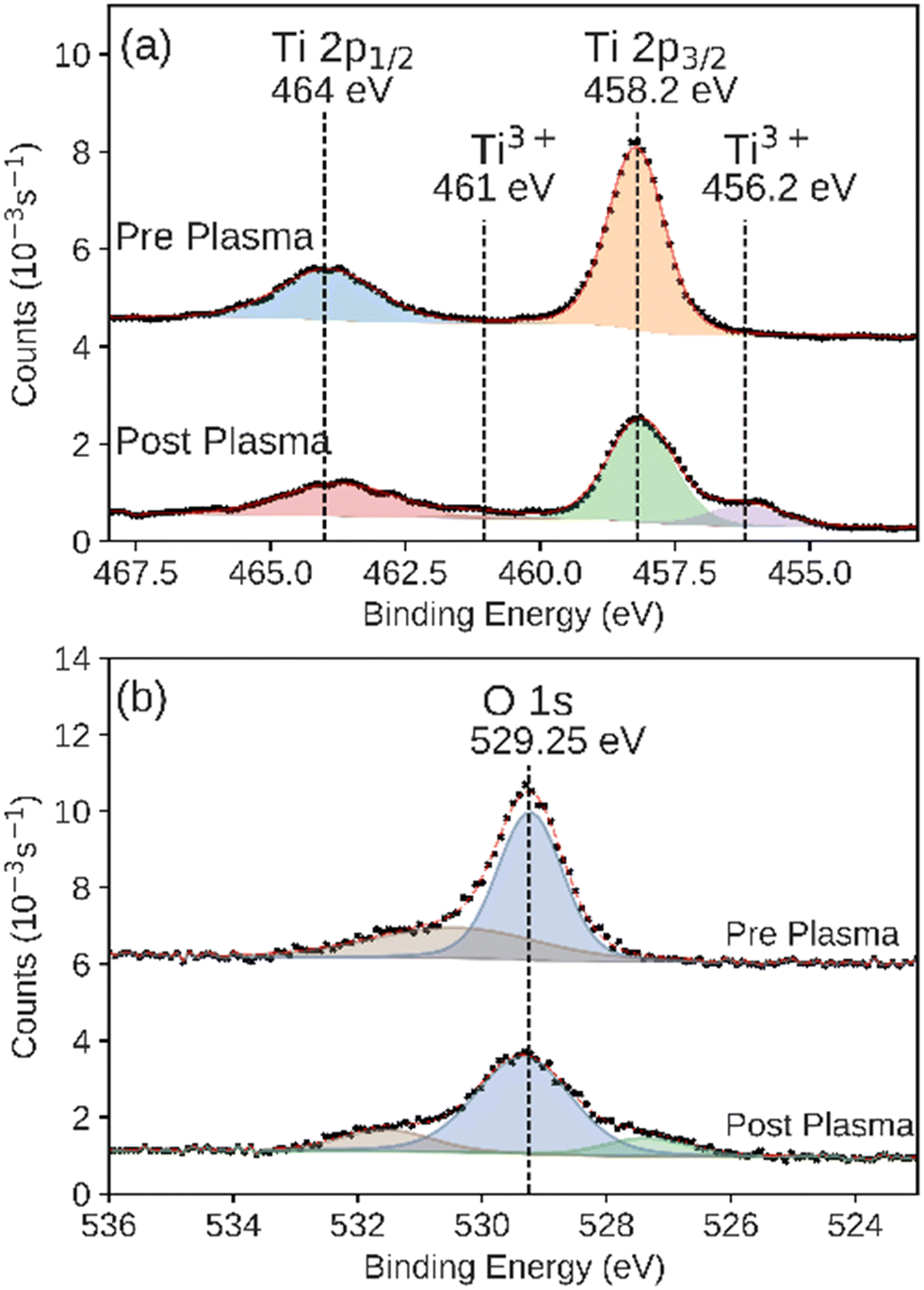 | ||
| Fig. 6 XPS of the (a) Ti 2p and (b) O 1s regions measured on the as prepared and post-plasma ALD-synthesized TiO2 catalyst. Black markers indicate raw data. Fitted peaks are shown in color with a red line showing the sum of the fit features. | ||
We observed that the integrated intensity of the signal attributed to Zn 2p3/2, Fig. 7, did not change significantly. Additionally we observed negligible intensity in the Al 2p and Si 2p XPS regions that would indicate the exposure of the base layers due to the disruption of the conformal ZnO catalyst (Fig. S4 and S5†). We also observed an additional feature in the O 1s XPS region, indicating adsorbed hydroxide on the surface.65 ALD-synthesized Al2O3 did not have a significant change during the plasma CO2 reduction process in either the Al 2p or O 1s XPS regions (Fig. 8a and b). While the Al 2p peak could not be used to assess the stability of this layer, no significant intensity was observed in the Si 2p XPS region of the post-plasma exposure Al2O3 catalyst.
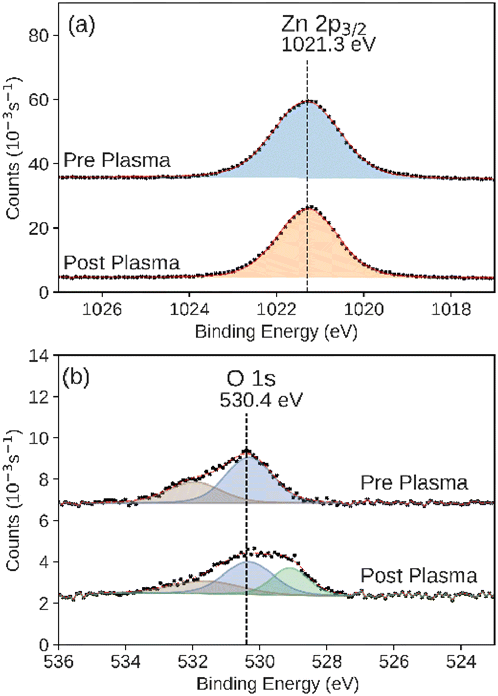 | ||
| Fig. 7 XPS of the (a) Zn 2p3/2 and (b) O 1s regions measured on the as-prepared and post-plasma ALD-synthesized ZnO catalyst. Black markers indicate raw data. Fitted peaks are shown in color with a red line showing the sum of the fit features. | ||
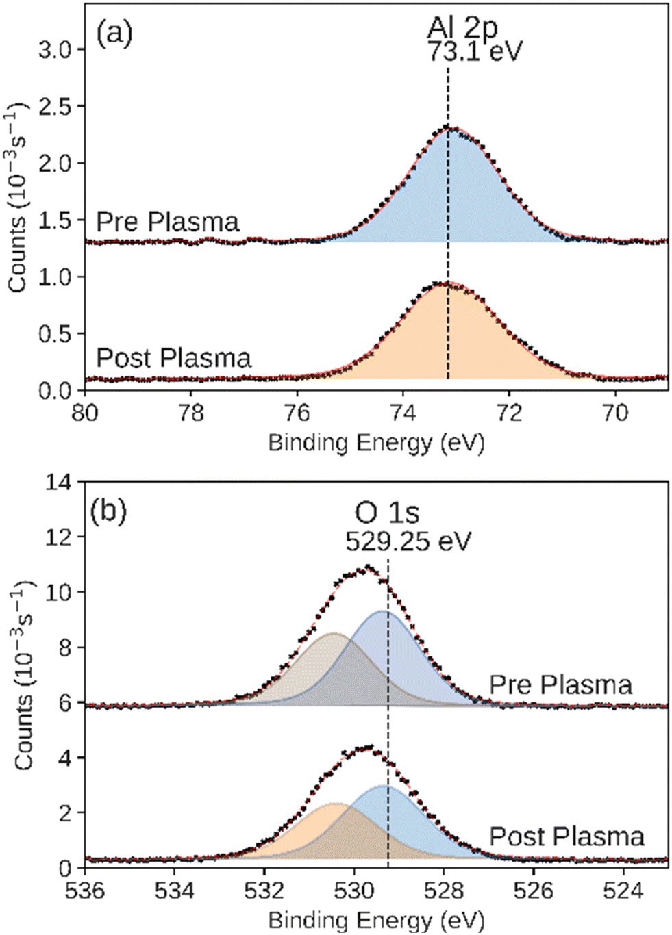 | ||
| Fig. 8 XPS of the (a) Al 2p and (b) O 1s regions measured on the as-prepared and post-plasma ALD-synthesized Al2O3 catalyst. Black markers indicate raw data. Fitted peaks are shown in color with a red line showing the sum of the fit features. | ||
It has been proposed that the decrease in performance for CO2 splitting into CO and O2 in a packed DBD reactor, as compared to a DBD reactor with no packing, is due to the modification of the discharge mode via a decrease in the number of filamentary discharges per unit time in the discharge region.57,66 In our system, the increase in performance by the bare support over the unpacked reactor suggests an increase in the number of overall discharges. The uniformity of the catalyst structure allowed us to regularize the dielectric material in the gap, and thus the overall nature of the plasma in the reactor. The exact growth rate of each material on the support is difficult to measure. We used rates determined by measuring deposition on planar Si wafers. While this is mostly the same growth mechanism, there is potentially some variability in the growth rates due to surface initiation and morphological differences. Thus, the catalyst layer thicknesses on the scaffold should only be considered accurate to one significant figure. The scaffold was therefore roughly 104 thicker than any of the catalyst layers here. Any differences in CO2 conversion can therefore be attributed to either the differences in catalytic activity for CO2 reduction due to the ALD-synthesized catalyst layer or electric field enhancement effects due to the permittivity of the ultra-thin catalyst layers when exposed to plasma. The extremely thin catalyst layers should have a negligible effect on the physical characteristics of the plasma, and the dielectric properties of the reaction volume are dominated by the permittivity of the support material.67,68 Given this approximation, the differences in the plasma itself near the surface of the catalyst should be negligible. Therefore, this approach produces regularized plasma catalysts for which any macroscopic changes in products can be ascribed to microscopic changes in activity. For example, the observed transition in the catalytic activity of ZnO is directly related to the reactivity of the material itself, rather than any morphological reconfiguration of the layer under plasma exposure. To our knowledge, this is the first report of this observation on ZnO.
Several factors can affect the interactions between CO2 molecules and the catalyst surface, and therefore the catalytic activity. The catalysts studied here represent a range of Lewis basicity, with relative basicity increasing in the order TiO2 < Al2O3 < ZnO.69 It has been shown that a higher catalyst Lewis basicity promotes the chemisorption of CO2 onto the surface, promoting CO2 dissociation, however this trend was not observed in conversion studies.9,70 The formation of oxide vacancies (Vo) during plasma exposure tends to increase the basicity of the surface. These Vo have been shown to act as active sites for plasma CO2 reduction and also increase the electron density of the adjacent metal cation and promote its interactions with the acidic carbon on CO2.71–74 The formation energies of Vo in Al2O3, TiO2 and ZnO have been reported to be 7.0 eV, 5.7 eV, and 4.1 eV respectively.71 This suggests that the formation of Vo would be suppressed on Al2O3 as compared to TiO2 or ZnO due to the higher energies required. This is supported by the observation of the formation of reduced metal centers on the TiO2 catalyst during CO2 plasma exposure. While we observed the presence of reduced Ti3+ on the surface of the TiO2 catalyst post plasma exposure, we did not observe reduced Zn in XPS measurements. We attribute this to the poor stability of Vo defects or reduced Zn in ZnO under air exposure.75 The adsorption energy of CO2 at an oxygen vacancy on the ZnO surface, has been calculated to be −0.60 eV.76 This is less favorable than the adsorption of CO2 onto an oxygen vacancy in TiO2, whose energy ranges from −2.53 eV to −0.98 eV depending on the location of the vacancy and the orientation of CO2.74 The formation energy difference suggests that ZnO would be expected to have a greater number of oxygen vacancies present on its surface compared to TiO2, particularly as the rate of the vacancy formation is increasing with input power. However, those vacancies would not be as capable of forming a bound CO2 adduct intermediate as strongly as TiO2. This might explain the slightly lower CO2 conversion rate observed on ZnO compared to TiO2 at low input power, where the populations of Vo would be relatively low and the greater CO2 adsorption energy would result in greater CO2 activation. At higher input powers, the greater population of available Vo in activated ZnO would contribute to the relatively improved performance over TiO2.
The results described here reinforce the significance of the formation of Vo in DBD catalysts for CO2 conversion. This also highlights the importance of understanding the contribution and activity of the support material when designing plasma CO2 conversion systems, as support materials such as ALD-ZnO and ALD-Al2O3 have been shown to have small but significant power-dependent activities that can influence conversions beyond support–catalyst interactions and plasma enhancement effects. The ALD synthesis method described here can be used in conjunction with other techniques, such as surface specific spectroscopy and more advanced reactor output product analysis to characterize the contribution of a support material more fully. Care should be taken to not underestimate the activity of the support and experiments should be designed as to ensure the activity of the support controlled when comparing multiple catalysts across wide input power ranges.
Conclusions
We isolated the catalytic effects of metal oxide catalysts for DBD plasma CO2 reduction processes by precisely synthesizing nanoscale layers with ALD. ALD allowed for control variations in structure, surface area, and electronic effects between catalysts. This allowed for the unambiguous study of the catalytic properties of each compound on under equivalent plasma and catalyst structure conditions. These studies show that these catalysts can withstand and be used for DBD plasma CO2 reduction for meaningful lengths of time and can be deposited onto support structures such that their affinities for CO2 reduction can be studied while maintaining identical bulk reactor properties such as flow rate, packing density, surface area and surface structure. The highest conversion efficiency was 2.6% utilizing the ALD-TiO2 at 15 W input power. ZnO, a common support material, showed an unexpected transition in its catalytic activity. At low power (15 W) it behaved like the bare support, while at high power (100 W) it yielded the highest overall CO2 conversion percentage (19.0%) of any catalyst. Post-catalyst studies showed that the ALD TiO2 and ZnO catalysts were resistant to carbon deposition when compared to ALD Al2O3. XPS studies showed the formation of reduced metal species on the TiO2 surface after the plasma reaction, which suggests the formation of active oxygen vacancies. Decoupling the macrostructure of the catalyst from the catalytically active surface composition in this way removes potential ambiguities in the interpretation of differences in catalytic effects in plasma CO2 reduction.Data availability
Data will be made available by the authors on reasonable request.Author contributions
Samuel K. Conlin: conceptualization, methodology, investigation, validation, writing – original draft. Hamed Mehrabi: methodology, validation, writing – review & editing. David N. Parette: methodology, validation, writing – review & editing. Eva M. Nichols: conceptualization, writing – review & editing, funding acquisition. Robert H. Coridan: conceptualization, validation, writing – original draft, supervision, funding acquisition.Conflicts of interest
The authors declare no competing financial interest.Acknowledgements
We acknowledge funding for this work from the Research Corporation for Science Advancement and the Negative Emissions Science Scialog® under Award Number SA-NES-2020-073.References
- B. Ekwurzel, J. Boneham, M. W. Dalton, R. Heede, R. J. Mera, M. R. Allen and P. C. Frumhoff, The Rise in Global Atmospheric CO2, Surface Temperature, and Sea Level from Emissions Traced to Major Carbon Producers, Clim. Change, 2017, 144(4), 579–590, DOI:10.1007/s10584-017-1978-0.
- W. M. Putman, L. Ott, A. Darmenov and A. daSilva, A Global Perspective of Atmospheric Carbon Dioxide Concentrations, Parallel Comput., 2016, 55, 2–8, DOI:10.1016/j.parco.2016.03.001.
- P. Friedlingstein, M. O'Sullivan, M. W. Jones, R. M. Andrew, J. Hauck, A. Olsen, G. P. Peters, W. Peters, J. Pongratz, S. Sitch, C. Le Quéré, J. G. Canadell, P. Ciais, R. B. Jackson, S. Alin, L. E. O. C. Aragão, A. Arneth, V. Arora, N. R. Bates, M. Becker, A. Benoit-Cattin, H. C. Bittig, L. Bopp, S. Bultan, N. Chandra, F. Chevallier, L. P. Chini, W. Evans, L. Florentie, P. M. Forster, T. Gasser, M. Gehlen, D. Gilfillan, T. Gkritzalis, L. Gregor, N. Gruber, I. Harris, K. Hartung, V. Haverd, R. A. Houghton, T. Ilyina, A. K. Jain, E. Joetzjer, K. Kadono, E. Kato, V. Kitidis, J. I. Korsbakken, P. Landschützer, N. Lefèvre, A. Lenton, S. Lienert, Z. Liu, D. Lombardozzi, G. Marland, N. Metzl, D. R. Munro, J. E. M. S. Nabel, S.-I. Nakaoka, Y. Niwa, K. O'Brien, T. Ono, P. I. Palmer, D. Pierrot, B. Poulter, L. Resplandy, E. Robertson, C. Rödenbeck, J. Schwinger, R. Séférian, I. Skjelvan, A. J. P. Smith, A. J. Sutton, T. Tanhua, P. P. Tans, H. Tian, B. Tilbrook, G. van der Werf, N. Vuichard, A. P. Walker, R. Wanninkhof, A. J. Watson, D. Willis, A. J. Wiltshire, W. Yuan, X. Yue and S. Zaehle, Global Carbon Budget 2020, Earth Syst. Sci. Data, 2020, 12(4), 3269–3340, DOI:10.5194/essd-12-3269-2020.
- O. S. Bushuyev, P. De Luna, C. T. Dinh, L. Tao, G. Saur, J. van de Lagemaat, S. O. Kelley and E. H. Sargent, What Should We Make with CO2 and How Can We Make It?, Joule, 2018, 2(5), 825–832, DOI:10.1016/j.joule.2017.09.003.
- S. Kaneco, K. Iiba, M. Yabuuchi, N. Nishio, H. Ohnishi, H. Katsumata, T. Suzuki and K. Ohta, High Efficiency Electrochemical CO2-to-Methane Conversion Method Using Methanol with Lithium Supporting Electrolytes, Ind. Eng. Chem. Res., 2002, 41(21), 5165–5170, DOI:10.1021/ie0200454.
- W. W. Wang, Z. P. Qu, L. X. Song and Q. Fu, CO2 Hydrogenation to Methanol over Cu/CeO2 and Cu/ZrO2 Catalysts: Tuning Methanol Selectivity via Metal-Support Interaction, J. Energy Chem., 2020, 40, 22–30, DOI:10.1016/j.jechem.2019.03.001.
- J. J. Torrez-Herrera, S. A. Korili and A. Gil, Recent Progress in the Application of Ni-Based Catalysts for the Dry Reforming of Methane, Catal. Rev.: Sci. Eng., 2021, 1–58, DOI:10.1080/01614940.2021.2006891.
- G. A. Olah, A. Goeppert, M. Czaun, T. Mathew, R. B. May and G. K. S. Prakash, Single Step Bi-Reforming and Oxidative Bi-Reforming of Methane (Natural Gas) with Steam and Carbon Dioxide to Metgas (CO-2H2) for Methanol Synthesis: Self-Sufficient Effective and Exclusive Oxygenation of Methane to Methanol with Oxygen, J. Am. Chem. Soc., 2015, 137(27), 8720–8729, DOI:10.1021/jacs.5b02029.
- X. Duan, Z. Hu, Y. Li and B. Wang, Effect of Dielectric Packing Materials on the Decomposition of Carbon Dioxide Using DBD Microplasma Reactor, AIChE J., 2015, 61(3), 898–903, DOI:10.1002/aic.14682.
- Z. L. Cui, S. Y. Meng, Y. H. Yi, A. Jafarzadeh, S. K. Li, E. C. Neyts, Y. P. Hao, L. C. Li, X. X. Zhang, X. K. Wang and A. Bogaerts, Plasma-Catalytic Methanol Synthesis from CO2 Hydrogenation over a Supported Cu Cluster Catalyst: Insights into the Reaction Mechanism, ACS Catal., 2022, 12(2), 1326–1337, DOI:10.1021/acscatal.1c04678.
- B. Ashford and X. Tu, Non-Thermal Plasma Technology for the Conversion of CO2, Curr. Opin. Green Sustainable Chem., 2017, 3, 45–49, DOI:10.1016/j.cogsc.2016.12.001.
- G. Centi, S. Perathoner and G. Papanikolaou, Plasma Assisted CO2 Splitting to Carbon and Oxygen: A Concept Review Analysis, J. CO2 Util., 2021, 54, 101775, DOI:10.1016/j.jcou.2021.101775.
- P. Koelman, S. Heijkers, S. Tadayon Mousavi, W. Graef, D. Mihailova, T. Kozak, A. Bogaerts and J. van Dijk, A Comprehensive Chemical Model for the Splitting of CO2 in Non-Equilibrium Plasmas, Plasma Processes Polym., 2017, 14(4–5), 1600155, DOI:10.1002/ppap.201600155.
- M. Zhu, S. Y. Hu, F. F. Wu, H. Ma, S. Y. Xie and C. H. Zhang, CO2 Dissociation in a Packed Bed DBD Reactor: Effect of Streamer Discharge, J. Phys. D: Appl. Phys., 2022, 55(22), 225207, DOI:10.1088/1361-6463/ac55c1.
- D. Ray, R. Saha and C. Subrahmanyam, DBD Plasma Assisted CO2 Decomposition: Influence of Diluent Gases, Catalysts, 2017, 7(9), 244, DOI:10.3390/catal7090244.
- M. C. Bacariza, M. Biset-Peiro, I. Graca, J. Guilera, J. Morante, J. M. Lopes, T. Andreu and C. Henriques, DBD Plasma-Assisted CO2 Methanation Using Zeolite-Based Catalysts: Structure Composition-Reactivity Approach and Effect of Ce as Promoter, J. CO2 Util., 2018, 26, 202–211, DOI:10.1016/j.jcou.2018.05.013.
- I. Michielsen, Y. Uytdenhouwen, J. Pype, B. Michielsen, J. Mertens, F. Reniers, V. Meynen and A. Bogaerts, CO2 Dissociation in a Packed Bed DBD Reactor: First Steps towards a Better Understanding of Plasma Catalysis, Chem. Eng. J., 2017, 326, 477–488, DOI:10.1016/j.cej.2017.05.177.
- X. Gao, J. Liang, L. Wu, L. Wu and S. Kawi, Dielectric Barrier Discharge Plasma-Assisted Catalytic CO2 Hydrogenation: Synergy of Catalyst and Plasma, Catalysts, 2022, 12(1), 66, DOI:10.3390/catal12010066.
- D. Ray, P. Chawdhury, K. V. S. S. Bhargavi, S. Thatikonda, N. Lingaiah and Ch. Subrahmanyam, Ni and Cu Oxide Supported γ-Al2O3 Packed DBD Plasma Reactor for CO2 Activation, J. CO2 Util., 2021, 44, 101400, DOI:10.1016/j.jcou.2020.101400.
- N. Joshi and L. Sivachandiran, Exploring the Feasibility of Liquid Fuel Synthesis from CO2 under Cold Plasma Discharge: Role of Plasma Discharge in Binary Metal Oxide Surface Modification, RSC Adv., 2021, 11(44), 27757–27766, 10.1039/D1RA04852J.
- X. Ma, S. Li, M. Ronda-Lloret, R. Chaudhary, L. Lin, G. van Rooij, F. Gallucci, G. Rothenberg, N. Raveendran Shiju and V. Hessel, Plasma Assisted Catalytic Conversion of CO2 and H2O Over Ni/Al2O3 in a DBD Reactor, Plasma Chem. Plasma Process., 2019, 39(1), 109–124, DOI:10.1007/s11090-018-9931-1.
- A. Bajpai and S. Kumar, Nonthermal Plasma-Assisted CO2-H2O Conversion over NiO and Co3O4 Supported on CeO2, Chem. Eng. Technol., 2023, 46(7), 1485–1493, DOI:10.1002/ceat.202200481.
- X. Tu and J. C. Whitehead, Plasma-Catalytic Dry Reforming of Methane in an Atmospheric Dielectric Barrier Discharge: Understanding the Synergistic Effect at Low Temperature, Appl. Catal., B, 2012, 125, 439–448, DOI:10.1016/j.apcatb.2012.06.006.
- X. Tu, H. J. Gallon and J. C. Whitehead, Electrical and Spectroscopic Diagnostics of a Single-Stage Plasma-Catalysis System: Effect of Packing with TiO2, J. Phys. D: Appl. Phys., 2011, 44(48), 482003, DOI:10.1088/0022-3727/44/48/482003.
- E. C. Neyts, K. Ostrikov, M. K. Sunkara and A. Bogaerts, Plasma Catalysis: Synergistic Effects at the Nanoscale, Chem. Rev., 2015, 115(24), 13408–13446, DOI:10.1021/acs.chemrev.5b00362.
- K. Stanley, S. Kelly and J. A. Sullivan, Effect of Ni NP Morphology on Catalyst Performance in Non-Thermal Plasma-Assisted Dry Reforming of Methane, Appl. Catal., B, 2023, 328, 122533, DOI:10.1016/j.apcatb.2023.122533.
- S. M. George, Atomic Layer Deposition: An Overview, Chem. Rev., 2010, 110(1), 111–131, DOI:10.1021/cr900056b.
- R. W. Johnson, A. Hultqvist and S. F. Bent, A Brief Review of Atomic Layer Deposition: From Fundamentals to Applications, Mater. Today, 2014, 17(5), 236–246, DOI:10.1016/j.mattod.2014.04.026.
- T. Justin Kunene, L. Kwanda Tartibu, K. Ukoba and T.-C. Jen, Review of Atomic Layer Deposition Process, Application and Modeling Tools, Mater. Today: Proc., 2022, 62, S95–S109, DOI:10.1016/j.matpr.2022.02.094.
- M. D. Groner, F. H. Fabreguette, J. W. Elam and S. M. George, Low-Temperature Al2O3 Atomic Layer Deposition, Chem. Mater., 2004, 16(4), 639–645, DOI:10.1021/cm0304546.
- B. J. O'Neill, D. H. K. Jackson, J. Lee, C. Canlas, P. C. Stair, C. L. Marshall, J. W. Elam, T. F. Kuech, J. A. Dumesic and G. W. Huber, Catalyst Design with Atomic Layer Deposition, ACS Catal., 2015, 5(3), 1804–1825, DOI:10.1021/cs501862h.
- Y. J. Pagán-Torres, J. M. R. Gallo, D. Wang, H. N. Pham, J. A. Libera, C. L. Marshall, J. W. Elam, A. K. Datye and J. A. Dumesic, Synthesis of Highly Ordered Hydrothermally Stable Mesoporous Niobia Catalysts by Atomic Layer Deposition, ACS Catal., 2011, 1(10), 1234–1245, DOI:10.1021/cs200367t.
- V. Cremers, R. L. Puurunen and J. Dendooven, Conformality in Atomic Layer Deposition: Current Status Overview of Analysis and Modelling, Appl. Phys. Rev., 2019, 6(2), 021302, DOI:10.1063/1.5060967.
- R. Zazpe, M. Knaut, H. Sopha, L. Hromadko, M. Albert, J. Prikryl, V. Gärtnerová, J. W. Bartha and J. M. Macak, Atomic Layer Deposition for Coating of High Aspect Ratio TiO2 Nanotube Layers, Langmuir, 2016, 32(41), 10551–10558, DOI:10.1021/acs.langmuir.6b03119.
- S. Kumakura, H. Sasagawa, T. Nishizuka, Y. Kihara and M. Honda, Novel Technology of High-Aspect-Ratio Etch Utilizing Coverage-Controllable Atomic Layer Deposition, Jpn. J. Appl. Phys., 2022, 61(SI), SI1015, DOI:10.35848/1347-4065/ac647e.
- M. R. Shaner, S. Hu, K. Sun and N. S. Lewis, Stabilization of Si Microwire Arrays for Solar-Driven H2O Oxidation to O2 (g) in 1.0 M KOH(Aq) Using Conformal Coatings of Amorphous TiO2, Energy Environ. Sci., 2015, 8(1), 203–207, 10.1039/C4EE03012E.
- N. P. Dasgupta, C. Liu, S. Andrews, F. B. Prinz and P. Yang, Atomic Layer Deposition of Platinum Catalysts on Nanowire Surfaces for Photoelectrochemical Water Reduction, J. Am. Chem. Soc., 2013, 135(35), 12932–12935, DOI:10.1021/ja405680p.
- M.-G. Jeong, Y. D. Kim, S. Park, P. Kasinathan, Y. K. Hwang, J.-S. Chang and Y.-K. Park, Preparation of ZnO/Al2O3 Catalysts by Using Atomic Layer Deposition for Plasma-Assisted Non-Oxidative Methane Coupling, J. Korean Phys. Soc., 2016, 68(10), 1221–1227, DOI:10.3938/jkps.68.1221.
- Z. Chen, G. Zhang, J. Prakash, Y. Zheng and S. Sun, Rational Design of Novel Catalysts with Atomic Layer Deposition for the Reduction of Carbon Dioxide, Adv. Energy Mater., 2019, 9(37), 1900889, DOI:10.1002/aenm.201900889.
- T. V. Ivanova, T. Hoder, M.-L. Kääriäinen, A. Komlev, R. Brandenburg and D. C. Cameron, Enhancement of Atmospheric Plasma Decomposition of Toluene Using Porous Dielectric Conformally Coated with Titanium Dioxide by Atomic Layer Deposition, Sci. Adv. Mater., 2014, 6(10), 2098–2105, DOI:10.1166/sam.2014.1984.
- S. N. Habisreutinger, L. Schmidt-Mende and J. K. Stolarczyk, Photocatalytic Reduction of CO2 on TiO2 and Other Semiconductors, Angew. Chem., Int. Ed., 2013, 52(29), 7372–7408, DOI:10.1002/anie.201207199.
- L. Liu, H. Zhao, J. M. Andino and Y. Li, Photocatalytic CO2 Reduction with H2O on TiO2 Nanocrystals: Comparison of Anatase, Rutile, and Brookite Polymorphs and Exploration of Surface Chemistry, ACS Catal., 2012, 2(8), 1817–1828, DOI:10.1021/cs300273q.
- S. Kreft, D. Wei, H. Junge and M. Beller, Recent Advances on TiO2-Based Photocatalytic CO2 Reduction, EnergyChem, 2020, 2(6), 100044, DOI:10.1016/j.enchem.2020.100044.
- D. H. Mei, X. B. Zhu, C. F. Wu, B. Ashford, P. T. Williams and X. Tu, Plasma-Photocatalytic Conversion of CO2 at Low Temperatures: Understanding the Synergistic Effect of Plasma-Catalysis, Appl. Catal., B, 2016, 182, 525–532, DOI:10.1016/j.apcatb.2015.09.052.
- Q. Huang, Z. Y. Liang, F. Qi, N. Zhang, J. Y. Yang, J. X. Liu, C. Q. Tian, C. F. Fu, X. S. Tang, D. F. Wu, J. M. Wang, X. Y. Wang and W. W. Chen, Carbon Dioxide Conversion Synergistically Activated by Dielectric Barrier Discharge Plasma and the CsPbBr3@TiO2 Photocatalyst, J. Phys. Chem. Lett., 2022, 13(10), 2418–2427, DOI:10.1021/acs.jpclett.2c00253.
- I. Adamovich, S. Agarwal, E. Ahedo, L. L. Alves, S. Baalrud, N. Babaeva, A. Bogaerts, A. Bourdon, P. J. Bruggeman, C. Canal, E. H. Choi, S. Coulombe, Z. Donkó, D. B. Graves, S. Hamaguchi, D. Hegemann, M. Hori, H.-H. Kim, G. M. W. Kroesen, M. J. Kushner, A. Laricchiuta, X. Li, T. E. Magin, S. Mededovic Thagard, V. Miller, A. B. Murphy, G. S. Oehrlein, N. Puac, R. M. Sankaran, S. Samukawa, M. Shiratani, M. Šimek, N. Tarasenko, K. Terashima, E. Thomas Jr, J. Trieschmann, S. Tsikata, M. M. Turner, I. J. van der Walt, M. C. M. van de Sanden and T. von Woedtke, The 2022 Plasma Roadmap: Low Temperature Plasma Science and Technology, J. Phys. D: Appl. Phys., 2022, 55(37), 373001, DOI:10.1088/1361-6463/ac5e1c.
- N. Bouchoul, H. Touati, E. Fourré, J.-M. Clacens, I. Batonneau-Gener and C. Batiot-Dupeyrat, Plasma-Catalysis Coupling for CH4 and CO2 Conversion over Mesoporous Macroporous Al2O3: Influence of the Physico-Chemical Properties, Appl. Catal., B, 2021, 295, 120262, DOI:10.1016/j.apcatb.2021.120262.
- X. Tu, H. J. Gallon, M. V. Twigg, P. A. Gorry and J. C. Whitehead, Dry Reforming of Methane over a Ni/Al2O3 Catalyst in a Coaxial Dielectric Barrier Discharge Reactor, J. Phys. D: Appl. Phys., 2011, 44(27), 274007, DOI:10.1088/0022-3727/44/27/274007.
- A. Górska, K. Krawczyk, S. Jodzis and K. Schmidt-Szałowski, Non-Oxidative Methane Coupling Using Cu/ZnO/Al2O3 Catalyst in DBD, Fuel, 2011, 90(5), 1946–1952, DOI:10.1016/j.fuel.2010.12.023.
- J. Li, Y. Sun, B. Wang, H. Xiao, J. Wu, L. Chen, M. Fu and D. Ye, Effect of Plasma on Catalytic Conversion of CO2 with Hydrogen over Pd/ZnO in a Dielectric Barrier Discharge Reactor, J. Phys. D: Appl. Phys., 2019, 52(24), 244001, DOI:10.1088/1361-6463/ab111b.
- Y. Sun, J. Li, P. Chen, B. Wang, J. Wu, M. Fu, L. Chen and D. Ye, Reverse Water-Gas Shift in a Packed Bed DBD Reactor: Investigation of Metal-Support Interface towards a Better Understanding of Plasma Catalysis, Appl. Catal., A, 2020, 591, 117407, DOI:10.1016/j.apcata.2019.117407.
- A. Berthelot and A. Bogaerts, Modeling of Plasma-Based CO2 Conversion: Lumping of the Vibrational Levels, Plasma Sources Sci. Technol., 2016, 25(4), 045022, DOI:10.1088/0963-0252/25/4/045022.
- R. Snoeckx, S. Heijkers, K. V. Wesenbeeck, S. Lenaerts and A. Bogaerts, CO2 Conversion in a Dielectric Barrier Discharge Plasma: N2 in the Mix as a Helping Hand or Problematic Impurity?, Energy Environ. Sci., 2016, 9(3), 999–1011, 10.1039/C5EE03304G.
- H. Zhang, L. Li, R. Xu, J. Huang, N. Wang, X. Li and X. Tu, Plasma-Enhanced Catalytic Activation of CO2 in a Modified Gliding Arc Reactor, Waste Dispos. Sustain. Energy., 2020, 2(2), 139–150, DOI:10.1007/s42768-020-00034-z.
- B. W. Wang, X. Y. Li, X. X. Wang and B. Zhang, Effect of Filling Materials on CO2 Conversion with a Dielectric Barrier Discharge Reactor, J. Environ. Chem. Eng., 2021, 9(6), 106370, DOI:10.1016/j.jece.2021.106370.
- Y. Uytdenhouwen, S. Van Alphen, I. Michielsen, V. Meynen, P. Cool and A. Bogaerts, A Packed-Bed DBD Micro Plasma Reactor for CO2 Dissociation: Does Size Matter?, Chem. Eng. J., 2018, 348, 557–568, DOI:10.1016/j.cej.2018.04.210.
- Y. Sun, J. Wu, Y. Wang, J. Li, N. Wang, J. Harding, S. Mo, L. Chen, P. Chen, M. Fu, D. Ye, J. Huang and X. Tu, Plasma-Catalytic CO2 Hydrogenation over a Pd/ZnO Catalyst: In Situ Probing of Gas-Phase and Surface Reactions, JACS Au, 2022, 2(8), 1800–1810, DOI:10.1021/jacsau.2c00028.
- J. Kim, D. B. Go and J. C. Hicks, Synergistic Effects of Plasma–Catalyst Interactions for CH4 Activation, Phys. Chem. Chem. Phys., 2017, 19(20), 13010–13021, 10.1039/C7CP01322A.
- P. Mehta, P. Barboun, F. A. Herrera, J. Kim, P. Rumbach, D. B. Go, J. C. Hicks and W. F. Schneider, Overcoming Ammonia Synthesis Scaling Relations with Plasma-Enabled Catalysis, Nat. Catal., 2018, 1(4), 269–275, DOI:10.1038/s41929-018-0045-1.
- B. Ashford, Y. L. Wang, C. K. Poh, L. W. Chen and X. Tu, Plasma-Catalytic Conversion of CO2 to CO over Binary Metal Oxide Catalysts at Low Temperatures, Appl. Catal., B, 2020, 276, 10, DOI:10.1016/j.apcatb.2020.119110.
- H. Burghaus, G. Herdrich and S. Fasoulas, Derivation of Species Distribution in Inductively Heated CO2 Plasma via Automated Spectral Fitting, Vacuum, 2021, 184, 109901, DOI:10.1016/j.vacuum.2020.109901.
- J. Saari, H. Ali-Löytty, K. Lahtonen, M. Hannula, L. Palmolahti, A. Tukiainen and M. Valden, Low-Temperature Route to Direct Amorphous to Rutile Crystallization of TiO2 Thin Films Grown by Atomic Layer Deposition, J. Phys. Chem. C, 2022, 126(36), 15357–15366, DOI:10.1021/acs.jpcc.2c04905.
- R. L. Kurtz and V. E. Henrich, Comparison of Ti 2p Core-Level Peaks from TiO2, Ti2O3, and Ti Metal, by XPS, Surf. Sci. Spectra, 1998, 5(3), 179–181, DOI:10.1116/1.1247874.
- B. Bharti, S. Kumar, H.-N. Lee and R. Kumar, Formation of Oxygen Vacancies and Ti(3+) State in TiO2 Thin Film and Enhanced Optical Properties by Air Plasma Treatment, Sci. Rep., 2016, 6, 32355, DOI:10.1038/srep32355.
- T. J. Frankcombe and Y. Liu, Interpretation of Oxygen 1s X-Ray Photoelectron Spectroscopy of ZnO, Chem. Mater., 2023, 35(14), 5468–5474, DOI:10.1021/acs.chemmater.3c00801.
- C. Douat, S. Ponduri, T. Boumans, O. Guaitella, S. Welzel, E. Carbone and R. Engeln, The Role of the Number of Filaments in the Dissociation of CO2 in Dielectric Barrier Discharges, Plasma Sources Sci. Technol., 2023, 32(5), 055001, DOI:10.1088/1361-6595/acceca.
- Y. Yang, W. Guo, X. Wang, Z. Wang, J. Qi and Y. Zhang, Size Dependence of Dielectric Constant in a Single Pencil-Like ZnO Nanowire, Nano Lett., 2012, 12(4), 1919–1922, DOI:10.1021/nl204353t.
- M. Nemancha, S. Rouaiguia, A. Belbah and B. Belfarhi, Dielectric Properties of Alumino-Silicate Ceramic Material, in Proceedings of 1995 IEEE 5th International Conference on Conduction and Breakdown in Solid Dielectrics, 1995, pp. 413–417, DOI:10.1109/ICSD.1995.523019.
- N. C. Jeong, J. S. Lee, E. L. Tae, Y. J. Lee and K. B. Yoon, Acidity Scale for Metal Oxides and Sanderson's Electronegativities of Lanthanide Elements, Angew. Chem., Int. Ed., 2008, 47(52), 10128–10132, DOI:10.1002/anie.200803837.
- D. Wierzbicki, M. V. Moreno, S. Ognier, M. Motak, T. Grzybek, P. Da Costa and M. E. Galvez, Ni-Fe Layered Double Hydroxide Derived Catalysts for Non-Plasma and DBD Plasma-Assisted CO2 Methanation, Int. J. Hydrogen Energy, 2020, 45(17), 10423–10432, DOI:10.1016/j.ijhydene.2019.06.095.
- A. M. Deml, A. M. Holder, R. P. O'Hayre, C. B. Musgrave and V. Stevanović, Intrinsic Material Properties Dictating Oxygen Vacancy Formation Energetics in Metal Oxides, J. Phys. Chem. Lett., 2015, 6(10), 1948–1953, DOI:10.1021/acs.jpclett.5b00710.
- A. V. Bakulin, L. S. Chumakova and S. E. Kulkova, Study of the Diffusion Properties of Oxygen in TiO2, J. Exp. Theor. Phys., 2021, 133(2), 169–174, DOI:10.1134/s1063776121070025.
- H. Han, S. Jin, S. Park, Y. Kim, D. Jang, M. H. Seo and W. B. Kim, Plasma-Induced Oxygen Vacancies in Amorphous MnOx Boost Catalytic Performance for Electrochemical CO2 Reduction, Nano Energy, 2021, 79, 105492, DOI:10.1016/j.nanoen.2020.105492.
- L. A. A. Varilla, N. Seriani and J. A. Montoya, Molecular Adsorption and Dissociation of CO2 on TiO2 Anatase (001) Activated by Oxygen Vacancies, J. Mol. Model., 2019, 25(8), 231, DOI:10.1007/s00894-019-4103-7.
- F. Yu, Z. Liu, Y. Li, D. Nan, B. Wang, L. He, J. Zhang, X. Tang, H. Duan and Y. Liu, Effect of Oxygen Vacancy Defect Regeneration on Photocatalytic Properties of ZnO Nanorods, Appl. Phys. A: Mater. Sci. Process., 2020, 126(12), 931, DOI:10.1007/s00339-020-04117-w.
- W. G. Reimers, M. A. Baltanás and M. M. Branda, CO, CO2 and H2 Adsorption on ZnO, CeO2, and ZnO/CeO2 Surfaces: DFT Simulations, J. Mol. Model., 2014, 20(6), 2270, DOI:10.1007/s00894-014-2270-0.
Footnote |
| † Electronic supplementary information (ESI) available. See DOI: https://doi.org/10.1039/d3lf00271c |
| This journal is © The Royal Society of Chemistry 2024 |