
High-performance cation electrokinetic concentrator based on a γ-CD/QCS/PVA composite and microchip for evaluating the activity of P-glycoprotein without any interference from serum albumin†
Runhui
Zhang‡
a,
Jun
Xu‡
a,
Jieqi
Deng
a,
Wei
Ouyang
b,
Hanren
Chen
a,
Qing
Tang
a,
Shiquan
Zheng
a and
Lihong
Liu
 *a
*a
aNMPA Key Laboratory for Research and Evaluation of Drug Metabolism, Guangdong Provincial Key Laboratory of New Drug Screening, School of Pharmaceutical Sciences, Southern Medical University, Guangzhou, 510515, China. E-mail: lhliu@smu.edu.cn
bThayer School of Engineering, Dartmouth College, Hanover, NH 03755, USA
First published on 27th November 2023
Abstract
The development of cation electrokinetic concentrators (CECs) has been hindered by the lack of commercial anion-exchange membranes (AEMs). This paper introduces a γ-cyclodextrin-modified quaternized chitosan/polyvinyl alcohol (γ-CD/QCS/PVA) composite as an AEM, which is combined with a microchip to fabricate a CEC. Remarkably, the CEC only concentrates cationic species, thereby overcoming the interference of the highly abundant, negatively charged serum albumin in the blood sample. P-Glycoprotein (P-gp) is recognized as an efflux transporter protein that influences the pharmacokinetics (PK) of various compounds. The CEC was used to evaluate the activity of P-gp by detecting the positively charged rhodamine 123 (Rho123 is a classical substrate of P-gp) with no interference from serum albumin in the serum sample. Using the CEC, the enrichment factor (EF) of Rho123 exceeded 105-fold under DC voltage application. The minimal sample consumption of the CEC (<10 μL) enables reduction of animal sacrifice in animal experiments. Here, the CEC has been applied to evaluate the transport activity of P-gp in in vitro and in vivo experiments by detecting Rho123 in the presence of P-gp inhibitors or agonists. The results are in good agreement with those reported in previous reports. Therefore, the CEC presents a promising application potential, owing to its simple fabrication process, high sensitivity, minimal sample consumption, lack of interference from serum albumin and low cost.
1. Introduction
P-Glycoprotein (P-gp), recognized as multidrug resistance protein 1 (MDR1), transports drug molecules into the intestine to prevent their absorption into the portal circulation.1 It also acts as an efflux transporter protein influencing the pharmacokinetics (PK) of various compounds.2 The changes in P-gp activity will directly affect the absorption and metabolism of drugs. Therefore, the analysis of P-gp activity is of great significance for understanding the bioavailability of drugs and evaluating drug–drug interactions.2 Rhodamine 123 (Rho123), which is transported extracellularly by multidrug resistant cells, is a classical substrate of P-gp. It is widely used to estimate the effects of various drugs on P-gp-mediated efflux activity3 and is therefore used by many laboratories, researchers, and medical institutions to carry out research into multidrug resistance and drug interactions. However, as we know, serum and plasma are key body fluid samples used to evaluate drugs, including blood concentration and pharmacokinetics studies. Serum albumin (SA), which is the most predominant protein in blood, can impede the accurate detection of Rho123 in various detection methods such as high-performance liquid chromatography (HPLC),4 leading to the need for intricate sample preparation. Considering that Rho123 is a positive ion, a method capable of focusing only on cations is promising to avoid the interference of proteins.Microchips integrated with ion concentration polarization (ICP) have received considerable attention and have been used to preconcentrate and detect low-abundance ions/molecules in many fields including clinical diagnostics,5 filtration,6 and desalination.7 However, there remains an unmet need for analyzing low-abundance cationic species in many applications, such as therapeutic drug monitoring,7,8 detection of positively charged peptides/proteins in serum,9 and determination of biological toxins in bodily fluids.10 Hitherto, only three studies have reported cation-selective electrokinetic preconcentration based on anion-permselective nanochannels due to the lack of commercially available anion-exchange membrane (AEM) materials to fabricate anion-permselective nanochannels in microchips. Shin et al.11 reported anion-permselective filters with two different kinds of nanochannels including an anion-permselective polymer membrane fabricated by photo-polymerization and positively-charged monomer/pre-formed polymer coated nanochannels, both involving complicated fabrication processes and requiring highly-trained personnel. The method introduced by Yamamoto et al.12 exhibited high sensitivity with an enrichment factor of 6400, but the reproducibility (20% RSD) of the method was unsatisfactory, due to the variation of the position of the hand-made electrode in the sample reservoir. Lee et al.13 reported a scalable multiscale-porous AEM that could achieve both ion and fluid transport. However, the enrichment factors of 250 and 500 could not meet the needs of clinical detection. In short, these techniques remain under development because of the limited preconcentration performance and complicated operations. A comparison of the strategies on the enrichment of cationic species is listed in Table S1.†
Herein, we introduced a γ-cyclodextrin-modified quaternized chitosan/polyvinyl alcohol (γ-CD/QCS/PVA) composite to fabricate an AEM for convenient integration with microchips. Since the γ-CD/QCS/PVA composite is liquid, it is easy to integrate with a microchip, facilitating the development of the γ-CD/QCS/PVA AEM integrated electrokinetic concentrator, which is the cation electrokinetic concentrator (CEC). The enrichment capability of the CEC was evaluated using positively charged Rho123, which was the substrate of P-gp. The enrichment factor (EF) of Rho123 exceeded 105-fold under DC voltage application. Remarkably, our CEC exhibited excellent performance in focusing Rho123 in serum with minimal interference from the SA, a major source of interference in biofluids in most detection techniques. Since there was no need for the pretreatment to remove the protein, the entire detection was completed in 35 min. To further investigate the applicability of the CEC, the transport activity of P-gp was evaluated by detecting Rho123 in in vitro experiments and in vivo experiments under verapamil (VER, P-gp inhibitor)14 and 18α-glycyrrhetinic acid (18α-GA, P-gp agonists)15 treatment. The results were consistent with those reported previously,14 indicating that the CEC holds promise for significantly advancing research and various applications involving cationic analytes.
2. Experimental section
2.1 Preparation of the γ-CD/QCS/PVA composite.
We prepared the γ-CD/QCS/PVA composite in two parts. In the first part, we prepared stock solutions of QCS (5% m/v) and PVA (8% m/v). First, QCS was synthesized following the procedure of the previous report.16 The reaction is shown in Scheme S1.† CS (20 g) was added into a three-necked, round-bottomed flask, and then glycidyl trimethyl ammonium chloride (GTAC, 50 ml) aqueous solution (20 g GTA dissolved in deionized water) was added to dissolve the chitosan. Magnetic stirring was conducted continuously for 10 h at 90 °C. In the meantime, 50% v/v isopropyl alcohol–water solution was slowly added. After the reaction was completed, the product (QCS) was placed in a vacuum drying oven at 60 °C until it reached a constant weight and then powdered by a mill. Afterward, the QCS powder (1.5 g) was added to a three-necked, round-bottomed flask containing a 30 ml aqueous solution of glacial acetic acid (2% v/v) and magnetic stirring was conducted continuously at 60 °C until complete dissolution. The product of the QCS solution (5% m/v) was sealed and stored at −4 °C. Second, a PVA stock solution (8% m/v) was prepared by adding PVA (5 g) to a flask containing deionized water (62.5 ml) and magnetic stirring was conducted continuously at 90 °C until complete dissolution. The product was sealed and stored at −4 °C. In the second part, we prepared the γ-CD/QCS/PVA composite. QCS (5% m/v, 100 μl) and PVA (8% m/v, 187.5 μl) were added to a 5 ml centrifuge tube and mixed thoroughly by stirring. γ-CD (10% m/v,75 μl) and GA (50% v/v, 20 μl) aqueous solutions were added to the mixture slowly. Afterward, MA (50% m/v, 20 μl) was added under stirring, followed by pouring the deionized water into the centrifuge tube until the total volume reached 500 μl. Lastly, the tube was heated at 60 °C for 60 min with stirring to complete the synthesis of the γ-CD/QCS/PVA composite. The final concentration (w/v%) of the γ-CD/QCS/PVA composite was estimated to be 7.12%.2.2 Fabrication of CEC
The silicon mold substrate for the PDMS microchips was fabricated using standard soft lithography techniques. The microchip contains an AEM line and a PDMS chip with Y- or H-shaped microchannels (width: 200 μm; height: 45 μm). AEM lines were fabricated using the microfluidic patterning method. In brief, the γ-CD/QCS/PVA composite (1.5 μl) was loaded into a dummy PDMS microchannel with a 45 μm thick and 200 μm wide straight microchannel and it completely filled the microchannel by applying a negative pressure on the other end of the channel. The dummy PDMS microchannel was removed and a smooth and neat AEM line was left on the glass substrate (Fig. S1†). The composite (AEM line) on the substrate was solidified into the AEM by heating at 60 °C for 3 min. At last, the AEM-patterned glass slide and the PDMS chip were treated with oxygen plasma and irreversibly bonded to obtain the desired PDMS chip. The AEM was placed perpendicular to the parallel microchannels and reservoirs were constructed using 10 μl bald pipet tips, which were inserted into the reservoirs of the PDMS chip.2.3 Capture of fluorescence images
Fluorescence images were recorded by an inverted fluorescence microscope (Leica DMIL LED, Ernst & Company, Vetzlar, Germany) equipped with a Leica L5 ET (excitation: 480 nm) and a CCD camera (Leica DFC 360 FX), and the images were taken using the software Leica application suite X. The exposure time of fluorescence images was 300 ms.2.4 Reusability tests
During the reusability tests, a 1 nM Rho123 sample was chosen as the validation analyte. The 0.5 × PBS (pH 3.5) was used selectively for the anodic reservoir when loading the Rho123 sample into the cathodic reservoir. After enrichment of the Rho123 samples, the channels in CEC were cleaned three times with deionized water for the next use.2.5 Bidirectional transport experiment of Rho123
The Caco-2 cell Transwell model was employed to investigate the transport of Rho123 in the presence VER and 18α-GA. The cell monolayers were rinsed twice with warm (37 °C) Hanks' balanced salt solution (HBSS) before the transport experiments. According to the different drugs, the experiment was divided into the control group, inhibitor group and agonists group. In the inhibitor group and agonists group, VER (50 μM) and 18α-GA (50 μM) were added to the apical side and incubated for 12 h, respectively. The control group was switched to HBSS buffer. The volume of incubation medium was 0.5 ml for both the apical (AP) and basolateral (BL) sides. For the P-gp substrate Rho123, the transport direction can be described using two directions, i.e. from the AP to the BL side (AP-BL) and from the BL side to the AP side (BL-AP). After incubation with the drug for a period of time, Rho123 (10 μM) was added to the AP or BL side and incubated with cell monolayers in fresh incubation medium at 37 °C. The permeability of Rho123 in all of the above conditions for both directions was measured after incubation for 30, 60, 90, 120, and 150 min at 37 °C, and then a 100 μl aliquot of the incubation solution was withdrawn at the indicated time points from the receiver compartment and replaced with the same volume of fresh pre-warmed HBSS buffer.2.6 Animals and ethics approval
SD rats (200 ± 20 g) were supplied by the Animal Experimental Center of Southern Medical University. All rats were kept in a 12 h light/dark cycle with a relative humidity of 50 ± 10%, temperature of 22 ± 2 °C, and free access to standard laboratory chow and tap water. The Southern Medical University Experimental Animal Ethics Committee approved animal experiments (approval IDs: L2022236) and all the animal studies complied with the Institutional Animal Guidelines of Southern Medical University.2.7 Pharmacokinetics study
The rats were randomly divided into 2 groups (3 rats per group) and then the rats were given saline or VER (5 mg kg−1) intragastrically 7 times per day. After 10 days of continuous gavage, fasting for 12 h started on the tenth night. Following this, all rats were administered with Rho123 (5 mg kg−1) intragastrically, and blood was drawn from the tail vein after 5, 10, 15, 30, 60, 90, 120, 240, 480, 720 and 1440 minutes. The plasma was then separated and stored at 4 °C, and the rats were allowed to drink freely in the intervals between blood collection.3. Results and discussion
3.1 Fabrication and characterization of γ-CD/QCS/PVA AEM
Fig. 1A presents the fabrication process of γ-CD/QCS/PVA AEM. The detailed synthetic process for the γ-CD/QCS/PVA composite was described in the Experimental section. In the reactants, QCS and PVA were the skeletons of γ-CD/QCS/PVA, where PVA had stable chemical properties and excellent film formation; QCS provided quaternary ammonium N+ cationic groups as anion exchange sites, and the degree of substitution (DS) of quaternization groups in QCS reached up to 75%, which was estimated from precipitation titration;17 γ-CD was used to regulate the distribution of hydrophilic and hydrophobic driving cationic groups to assemble into hydrophilic domains and form ion channels.18 The presence of the functional groups of the γ-CD/QCS/PVA AEM composite was verified by FTIR analysis (Fig. S2†). In the FTIR analysis, a characteristic peak appeared at 1644 cm−1, which was attributed to the bending vibration of C–N in the secondary amine structure. The absorption peak at 1480 cm−1 was attributed to the bending vibration of C–H in the quaternary amine group. The –CH stretching vibration peak of the aldehyde group appeared at 2910 cm−1, indicating that the cross-linking reaction occurred in the AEM interior. Remarkably, the γ-CD/QCS/PVA composite was in the liquid state which could be fully cross-linked to form AEM with a dense interpenetrating network structure by heating at 60 °C for only 3 min. The structural information of the γ-CD/QCS/PVA AEM morphology was investigated through scanning electron microscopy (SEM) and transmission electron microscopy (TEM). As shown in Fig. 1B, the SEM image of the AEM shows obvious surface folds and a compact structure. This compact structure could protect the quaternary ammonium N+ group, which is conducive to ion transport.19 In addition, the SEM of the AEM in a hydrated state indicated that the internal groups of the AEM composites are fully cross-linked, forming a uniform network structure (Fig. S3†). Fig. 1C shows a TEM image of the AEM, where the darker regions represented the hydrophilic domains of ion clusters, whereas bright areas corresponded to the hydrophobic domains formed by hydrophobic polymer backbones.20 From the TEM images, the hydrophilic/hydrophobic microphase separation can be clearly seen in the AEM, and the hydrophilic domains with an average diameter of 2–3 nm highly interconnected with each other and further formed continuous hydrophilic ion channels in γ-CD/QCS/PVA AEM.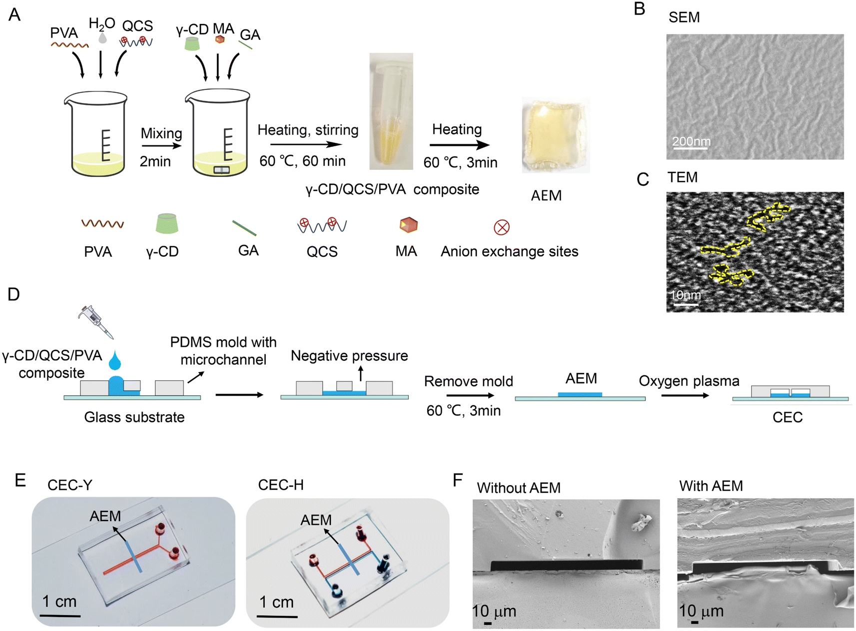 | ||
| Fig. 1 Fabrication and characteristics of γ-CD/QCS/PVA AEM and CEC. (A) A schematic illustration of the fabrication process of γ-CD/QCS/PVA AEM. (B) Scanning electron microscopy (SEM) images of the AEM. (C) Transmission electron microscopy (TEM) images of the AEM. (D) A schematic illustration of the fabrication process of CEC. (E) Photos of the CEC-Y and CEC-H. (F) SEM images of a longitudinal section of the microchannels without and with AEM integrated with a microfluidic chip. | ||
3.2 Fabrication and structure of CEC
Our γ-CD/QCS/PVA AEM composite is liquid, providing greater flexibility for integration with a microfluidic chips. The specific fabrication process of CEC is shown in Fig. 1D. In this study, two CECs were fabricated by integrating AEM with the Y-shaped chip (CEC-Y) and H-shaped chip (CEC-H), respectively (Fig. 1E). Fig. 1F shows the longitudinal section of the SEM of the microchannels without and with AEM in the microfluidic chip. In CEC, the AEM thin strips were deposited on the glass substrate and a microchannel was formed above the AEM. In this configuration, the AEM induces an ion-selective current and the microchannel supports the fluid flow.21 The images around the AEM membrane are shown in Fig. S4.†3.3 Enrichment principle of the CEC
ICP is a fundamental electrokinetic process that occurs near a nanojunction or an ion permselective membrane under a DC voltage, which enables efficient trapping and preconcentration of a charged molecule.22–26 The current through a permselective membrane under DC voltage is characterized by the formation of an ion depletion zone (IDZ) and ion concentration regions at the opposite ends of the membrane. At the outer-boundary of the IDZ, ion preconcentration was achieved when the ions were simultaneously subjected to both an electrophoretic force and a force opposite to the electrophoretic forces.22,27–30 In the PDMS microchannel wall, the net charges on the microchannel wall of PDMS and glass-integrated microfluidic chips are negative, the electroosmotic flow (EOF) is generated under the tangential electric field and drives the solution toward the cathode.31 However, cations also migrate toward the cathode under positive DC voltage, resulting in a very low enrichment efficiency. Therefore, the reverse EOF is used as a feed driver. In this study, we selected the positively charged poly dimethyl diallyl ammonium chloride (PDDAC) to modify the PDMS microchannel wall to obtain the reversed EOF (toward the anode). As shown in Fig. 2A, the enrichment ability was nearly 27-fold higher after modification with 0.1% PDDAC on the inner surface of the microchannel compared with that of the microchannels without the PDDAC coating.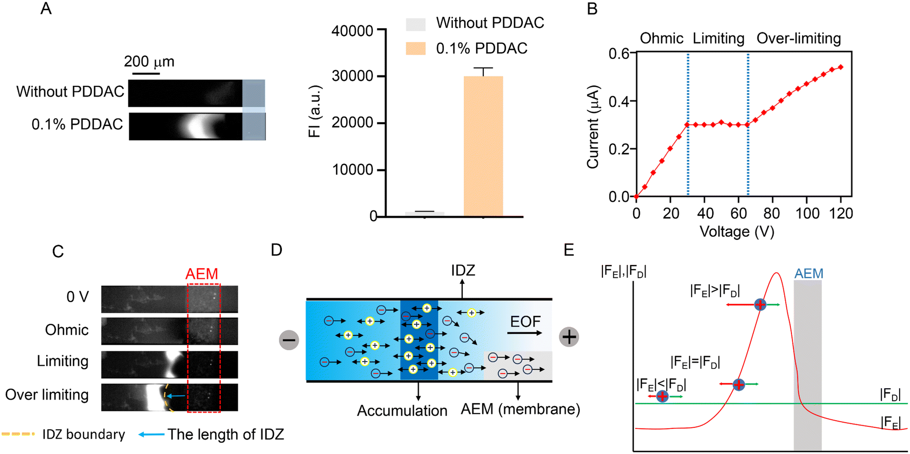 | ||
| Fig. 2 Enrichment principle of the CEC. (A) Enrichment ability of 1 nM Rho123 in CEC with and without 0.1% PDDAC modification. Conditions: γ-CD/PVA/QCS AEM (3% PVA, 1% QCS, 2% GA, 2% MA and 1.5% γ-CD), buffer 0.5 × phosphate-buffered saline (PBS) (pH 3.5); AEM microchannel, dimension: 200 μm width and 45 μm depth; and 150 V voltage. (B) Current–voltage characteristic of the CEC. (C) Fluorescent images of the IDZ near the AEM under different voltages. (D) Schematics of electrokinetic enrichment on CEC. (E) Distribution of FD and FE to the cations in the microchannel. FE means the electrophoresis force and FD means the fluid flow drag force applied by EOF. FI means fluorescence intensity. | ||
An important feature of the ion flow through the ion selective membrane is that the application of a DC voltage induces the flow of ionic currents through the membrane in three distinguishable regimes (called Ohmic/Limiting/Over limiting current regimes).27 Here, the H-chip was used to verify the anion perm-selectivity of CEC for Rho123. The current–voltage characteristics of the AEM corresponding to the varying regions are shown in Fig. 2B. The results were consistent with the current–voltage characteristics of the classical H microfluidic chip.13 The fluorescence images in Fig. 2C shows the IDZ near the AEM, corresponding to different voltage conditions. At low voltages, these regions were not observed due to inconspicuous concentration polarization. In the limiting region, IDZ gradually expanded due to significant concentration polarization, and the fluorescence intensity (FI) on the anode side of AEM increased. In the over-limit regime, cation enrichment further increased the FI on the anode side. Thus, it can be concluded that the CEC possessed a robust anion perm-selective property. Fig. 2D shows the mechanism of the CEC for the electrokinetic enrichment of cationic analytes. The sample was loaded in the cathode sample reservoir. The reversed EOF, which applies a rightward fluid flow drag force (FD) on the particles, drove the overall fluid flow from the cathode to the anode when a voltage was applied. The anions moved toward the anode under the electrophoretic force (FE) and FD and crossed the AEM with highly positive charges and high conductivity. Due to the fact that local pumping of anions by the AEM could not be compensated for, a lower concentration of anions at this interface and a lower concentration of cations were required by the electroneutral conditions of the electrolyte, resulting in the formation of the IDZ on the cathode side of AEM. Furthermore, the direction of cationic FE was opposite to the direction of FD, and cations were repelled by the ion-selective current and additional EOF induced by AEM too.32 When the FE of cations was equal in magnitude but opposite to the FD, the electric field kept the cations in dynamic equilibrium and produced an accumulation of samples at the edge of IDZ (Fig. 2E).33,34 Based on the properties of the ion selectivity and the electrokinetic enrichment induced by CEC, the stacking performances of different cationic analytes are shown in Fig. S5,† including cationic brilliant red (CBR), berberine (BER), and Rho123.
3.4 Assay optimization
In order to achieve the best ion transport and enrichment performance, as well as excellent mechanical strength and film-forming ability, the mass proportion of PVA, QCS and γ-CD in AEM was optimized by the CEC-Y. The selected optimization ranges of PVA, QCS and γ-CD were 0.5–4%, 0.25–2% and 0.5–2.5%, respectively. PVA exhibited a film-forming ability, which was instrumental in facilitating membrane formation and ensuring the mechanical robustness of the AEM network structure.35 Nonetheless, a high PVA content leads to a compacted AEM structure, impeding the efficient transport of ions. The presence of quaternary ammonium cationic groups in QCS served as the primary anion transport sites, thereby influencing the AEM's ionic transport efficiency and electrical conductivity.36 As shown in Fig. S6 and S7,† CEC-Y achieved excellent electrokinetic stacking effects on Rho123 when the content of PVA and QCS reached 3% and 1%, respectively. In addition, the external surface of CDs is hydrophilic because of the presence of the abundant hydroxyl groups on the rim; such a surface may undergo strong interactions with the multi-cationic groups from the cross-links to form hydrophilic domains.37 Therefore, CDs were used to regulate the distribution of hydrophilic and hydrophobic regions, driving cationic groups to assemble into hydrophilic domains and form ion channels.18 As shown in Fig. S8,† the ion stacking efficiency of AEM was significantly improved with the addition of 1.5% γ-CD. The enrichment ability of CEC-Y on Rho123 was nearly 5-fold higher compared with AEM without γ-CD modification. In addition, the enrichment performances of different types of CD modification for AEM were compared (Fig. S9†), the result indicated that γ-CD-modified AEM had a higher stacking ability than that of the others. The final optimal content of each component is presented in Table S2.† The effect of different concentrations of the γ-CD/QCS/PVA composite on CEC enrichment performance was also investigated. The CEC showed an excellent enrichment performance when the γ-CD/QCS/PVA composite concentration was 7.12% (Fig. S10†).3.5 Performance of CEC
To explore the cationic enrichment capacity of the CEC, the enrichment factor (EF) was investigated. To estimate the EF, the fluorescent intensity of the standard samples (3.6 and 20 μM) was measured. Compared with the standard Rho123 at 30 pM, the maximum EF of the CEC-H reached 120![[thin space (1/6-em)]](https://www.rsc.org/images/entities/char_2009.gif) 000 (Fig. 3A). We also investigated the EF of CEC-Y for the initial Rho123 sample with concentrations of 30 pM and 300 pM. The progress of Rho123 stacking in the CEC-Y is plotted in Fig. 3B. The EF using the Y-shape chip is calculated to be 10000. The CEC-H includes two microchannels, four electrodes, and an AEM that connects the microchannels. The sample channel is located between the anode and cathode, which creates a tangential electrical field (ET), and the electrodes of the buffer channel are electrically grounded (VG) which create a normal electrical field (EN) to AEM. EN and ET are controlled independently. EN predominantly drives ion transport through the AEM, which triggers the ICP. ET predominantly drives the electroosmosis (of the first kind). In this configuration, EN is typically much stronger than ET. A strong EN augments the ICP and creates a strong locally amplified field in the IDZ, which more efficiently blocks the leakage of the analyte downstream and at the same time increases the injection rate of the analyte by enhancing electroosmosis of the second kind. These two combined effects lead to a better preconcentration performance. In comparison, the CEC-Y has only one sample channel and the buffer channel is eliminated. The AEM is interconnected to the Y-shape sample channel. Both the ICP and electroosmosis are driven by the voltage between the anode/cathode and cannot be decoupled. Without a strong EN as in CEC-H, the preconcentration performance is compromised.27
000 (Fig. 3A). We also investigated the EF of CEC-Y for the initial Rho123 sample with concentrations of 30 pM and 300 pM. The progress of Rho123 stacking in the CEC-Y is plotted in Fig. 3B. The EF using the Y-shape chip is calculated to be 10000. The CEC-H includes two microchannels, four electrodes, and an AEM that connects the microchannels. The sample channel is located between the anode and cathode, which creates a tangential electrical field (ET), and the electrodes of the buffer channel are electrically grounded (VG) which create a normal electrical field (EN) to AEM. EN and ET are controlled independently. EN predominantly drives ion transport through the AEM, which triggers the ICP. ET predominantly drives the electroosmosis (of the first kind). In this configuration, EN is typically much stronger than ET. A strong EN augments the ICP and creates a strong locally amplified field in the IDZ, which more efficiently blocks the leakage of the analyte downstream and at the same time increases the injection rate of the analyte by enhancing electroosmosis of the second kind. These two combined effects lead to a better preconcentration performance. In comparison, the CEC-Y has only one sample channel and the buffer channel is eliminated. The AEM is interconnected to the Y-shape sample channel. Both the ICP and electroosmosis are driven by the voltage between the anode/cathode and cannot be decoupled. Without a strong EN as in CEC-H, the preconcentration performance is compromised.27
 | ||
| Fig. 3 Performance of CEC. Enrichment performance for Rho123 of the CEC-H (A) and CEC-Y (B). (C) CEC-Y enrichment efficiency of 1 nM Rho123 in PBS buffers with different concentrations. (D) CEC-Y enrichment efficiency of 1 nM Rho123 in the serum matrix with different concentrations. (E) Effect of the γ-CD/QCS/PVA composite storing time on the enrichment efficiency of CEC-Y. (F) Reusability of CEC, the buffer was 0.5× PBS, Rho123 samples (1 nM). (G) The fluorescent bands and calibration curve of Rho123 standard solutions, the buffer was 0.5× PBS. Conditions: 0.1% PDDAC on the inner surface of the microchannel, other conditions as in Fig. 2A; error bar: SD, n = 3. | ||
The high ionic strength of buffers is a major challenge of electrokinetic enrichment, which leads to thinning of the electric double layer (EDL) and inefficient ion selective enrichment.23 To explore the effect of buffer ionic strength on the electrokinetic enrichment of this system, different concentrations of PBS buffers were investigated using CEC-Y with 1 nM Rho123 as the sample solution. As shown in Fig. S11† and 3C, stable fluorescent bands and FI of Rho123 were obtained even using 1× PBS as buffer. To investigate the anti-interference performance of CEC, human serum samples at 1%, 2% and 5% were used as sample matrixes of Rho123. The stable fluorescence bands (Fig. S12†) and FI (Fig. 3D) of Rho123 in serum samples with different concentrations indicated the excellent robustness of our system against the interference from human serum albumin (HSA). This is because the negatively charged HSA can pass through the AEM while cationic components are stacked in front of the AEM. The storage stability of the γ-CD/QCS/PVA AEM composite was explored, too. Fig. S13† and 3E reveals that the AEM composite could still be integrated into microfluidic chips and the enrichment efficiency of Rho123 did not change significantly after 10 days of storage at room temperature. The decreased preconcentration performance observed after prolonged storage induced by the Hoffmann elimination reaction, which occurred after OH− nucleophilic attack on the quaternary ammonium cationic groups (N+ cationic groups) in QCS.38,39 In addition, the reusability of CEC also directly reflects the stability and economic applicability. Our CEC-Y retained a stable enrichment efficiency after multiple runs (Fig. S14† and 3F), which greatly reduced the testing cost. The reusability of CEC was also evaluated using 1 nM Rho123 in 1% serum samples (Fig. S15†), indicating that our CEC retained a stable enrichment efficiency after multiple runs of the complex sample matrixes.
The parameters related to quantitative analysis were measured using CEC-Y. A good linear relationship was found between the FI (y) and the concentration range of Rho123 from 10 to 3000 pM (x) (Fig. 3G). The regression equation was described by the formula: y = 20.595x + 2297.42 (R2 = 0.990) with a limit of detection of 2.6 pM (S/N = 3) and a limit of quantification of 8.83 pM (S/N = 10). A comparison of the strategies on the analysis of Rho123 is listed in Table S3.† In exploring the cationic enrichment capacity of the CEC, the CEC-H demonstrated superior enrichment efficiency compared to CEC-Y. However, CEC-Y also exhibited a notable EF up to 10000 and the LOD of CEC-Y for Rho123 detection was determined to be 2.6 pM (1 pg mL−1), fully satisfying the requirements for detecting Rho123 in biological samples (the minimum concentration was 20 ng mL−1, 200 pg mL−1 in 1% serum).40 In addition, the design of CEC-Y only required two voltage inputs, but the CEC-H required four electrodes and four reservoirs, resulting in a more complicated physical connection than that of CEC-Y. Considering the above, CEC-Y was chosen for the analysis of Rho123 in biological samples.
The precision of the method was assessed by repeatability. The relative standard deviation (RSD) values were 4.1% and 5.0% for intra-day and inter-day analyses of 1 nM Rho123, respectively. To investigate the accuracy of the CEC method, the recoveries were performed by spiking known concentrations of Rho123 in the cell culture medium of the Caco-2 cell line and 1% (v/v) serum, respectively. Low (50 pM), medium (500 pM) and high (2000 pM) concentrations of Rho123 were detected, respectively. The mean recoveries were 103.5% and 104.7% in the cell culture medium of the Caco-2 cell line and 1% (v/v) serum, respectively, indicating that the developed method was accurate (Table S4†). Furthermore, our CEC was cost-effective. The overall cost of materials for the γ-CD/PVA/QCS AEM composite per 1300 μL was about US$ 0.104. Each CEC needed about 1.3 μL γ-CD/PVA/QCS AEM composite (about US$ 0.000104), so one CEC cost about US$ 0.21 (Table S5†). The above results indicate that our CEC method exhibits good precision, sensitivity and accuracy in addition to its simplicity, ease of use, and low cost.
3.6 Application of CEC-Y
The analysis of P-gp expression and activity is of great significance for understanding the bioavailability of drugs and evaluating drug–drug interactions.2 Rho123 is widely used to estimate the effect of various drugs on P-gp-mediated efflux activity.3 Here, to explore the applicability of CEC-Y, we determined Rho123 in in vitro experiments in Caco-2 cells and in vivo experiments in SD rats to explore the function and activity of P-gp under P-gp inhibitor (VER)41 or P-gp agonist (18α-GA)15 treatment, respectively.In the in vitro experiments in Caco-2 cells, 50 μM was chosen as the concentration of VER and 18α-GA according to the result of the cytotoxicity tests (Fig. S16†). In bidirectional permeability experiments, the efflux ratio (ER), which is the ratio of the apparent permeability coefficient (Papp) of a compound in the AP-BL direction (Papp AP-BL, absorption) and the BL-AP direction (Papp BL-AP, secretion), has been widely used to measure the effect of the P-gp-mediated efflux activity on Rho123.42 As shown in Fig. 4A, the bidirectional permeability ER of Rho123 was 2.42 ± 0.24 in the control group without drug treatment. Compared with the control group, Rho123 ER was less than 2 in the VER treatment group and the difference of ER was significant (1.25 ± 0.11 vs. 2.42 ± 0.24, P < 0.01). Conversely, the ER value increased significantly in the 18α-GA treatment group (6.39 ± 0.27 vs. 2.42 ± 0.24, P < 0.001). This is because VER inhibited the expression of P-gp in Caco-2 monolayer cells, thereby improving the bioavailability of Rho123. In addition, 18α-GA induced the expression of P-gp and increased the efflux of Rho123. The result was in good agreement with previous studies,41,42 indicating that our CEC-Y was a reliable method to measure P-gp expression or transport activity.
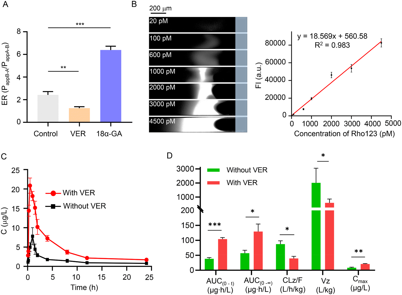 | ||
| Fig. 4 Application of CEC-Y. (A) ERs of Rho123 in VER, 18α-GA and control groups, respectively. (B) Standard curve of Rho123 in 1% rat plasma. (C) Plasma concentration-time profiles of Rho123 in rats with or without VER pretreatment. (D) Pharmacokinetic parameters of Rho123 in rats with or without treatment of VER. Error bar: SD, n = 3. Statistical significance was analyzed by one-way ANOVA, *P < 0.05, **P < 0.01 and ***P < 0.001. | ||
The determination of Rho123 in serum for the evaluation of P-gp activity in vivo is important for the research of multidrug resistance and drug interactions in many laboratories and medical institutions.43 In order to verify the feasibility of the CEC-Y in in vivo experiments in SD rats, the effect of VER on Rho123 bioavailability was determined. As shown in Fig. 4B, a good linearity (R2 = 0.983) was obtained in the range of 20–4500 pM for Rho123 in 1% rat plasma. The concentration-time curves of Rho123 in the presence or absence of VER are shown in Fig. 4C. Meanwhile, the pharmacokinetic parameters were calculated by the non-compartmental method using the DAS 3.0 pharmacokinetic software and the results are summarized in Fig. 4D and Table S6.† The administration of VER significantly increased the peak plasma concentration (Cmax, P < 0.01), AUC(0−t) (P < 0.001), AUC(0−∞) (P < 0.05), and significantly decreased the clearance rate (CLz/F, P < 0.05) and apparent volume of distribution (Vz, P < 0.05). The results are in good agreement with the reported result of a prior study,14 indicating that our CEC-Y can be used in in vivo experiments to investigate drug bioavailability and P-gp activity in vivo. It is noteworthy that the detection based on CEC needs less than 1 μL blood, thus a concentration time curve can be obtained by the blood concentration of the same animal, which not only helps to limit inter-animal variability but also reduces the number of animals needed in studies comparing different drug triggers. Therefore, we believe that the CEC is an alternative method, which not only helps to adhere to the principles of reduction and refinement in animal experiments but which also provides reliable data.
4. Conclusions
In summary, we have introduced the γ-CD/QCS/PVA composite as a precursor solution for an AEM, integrated with microfluidic chips. Based on the novel and highly efficient CEC, the EFs of CEC-H and CEC-Y could reach up to 120000 and 10000-fold for Rho123, respectively. Furthermore, this method could be used in samples with complex samples such as a 5% serum sample without the need for removal of serum proteins prior to detection, and thus the samples require no complex pretreatment and can be used for detection after simple dilution of the serum. In addition, the γ-CD/QCS/PVA composite is liquid, which means it can be cured into arbitrary shapes for convenient integration with other sophisticated microfluidic chips. Remarkably, the CEC-Y exhibited excellent performance in evaluating the transport properties of P-gp related to multidrug resistance by detecting Rho123 in in vitro experiments in Caco-2 cells and in vivo experiments in SD rats, indicating that it provides an alternative to current techniques for the assessment of drug effects on P-gp expression and transport activity. Owing to the minimal sample consumption of this method (<10 μL), a concentration–time curve can be drawn by collecting blood samples from the same animal. As a result, this method enables reduction of animal sacrifice in animal experiments. Meanwhile, due to the lack of interference from serum proteins, no complex sample pretreatment is required when using our CEC and the analysis can be finished within 35 min of obtaining the blood sample. All in all, the CEC has the advantages of simple fabrication, minimal sample consumption, high sensitivity and low cost, showing its potential for applications in multiple areas of cationic enrichment.
Author contributions
Runhui Zhang: software, writing – original draft, formal analysis, data curation, software. Jun Xu: writing – original draft, conceptualization, methodology. Jieqi Deng: investigation, visualization, validation. Wei Ouyang: writing – review & editing. Hanren Chen: visualization, validation. Qing Tang: visualization. Shiquan Zheng: validation. Lihong Liu: project administration. writing – review & editing, methodology, funding acquisition.Conflicts of interest
The authors declare that they have no known competing financial interests or personal relationships that could have appeared to influence the work reported in this paper.Acknowledgements
The study was financially supported by the Natural Science Foundation of China (Grant No. 81973282), Guangdong Basic and Applied Basic Research Foundation (Grant No. 2021A1515011493 and 2023A1515010996), and Science and Technology Innovation Strategic Special Project of Guangdong Province (“Climbing Program” Special Project. Grant No. pdjh2022b0106).References
- N. Sugihara, K. Toyama, A. Michihara, K. Akasaki, H. Tsuji and K. Furuno, Toxicology, 2006, 223, 156–165 CrossRef CAS PubMed.
- W. Zhang, T. M. Tan and L. Y. Lim, Drug Metab. Dispos., 2007, 35, 110–115 CrossRef CAS PubMed.
- M. Kageyama, K. Fukushima, T. Togawa, K. Fujimoto, M. Taki, A. Nishimura, Y. Ito, N. Sugioka, N. Shibata and K. Takada, Biol. Pharm. Bull., 2006, 29, 779–784 CrossRef CAS PubMed.
- S. Senthilkumari, T. Velpandian, N. R. Biswas, R. Saxena and S. Ghose, Curr. Eye Res., 2009, 33, 333–343 CrossRef PubMed.
- S. Wang, D. Sarenac, M. H. Chen, S. H. Huang, F. F. Giguel, D. R. Kuritzkes and U. Demirci, Int. J. Nanomed., 2012, 7, 5019–5028 Search PubMed.
- A. C. Barksdale, J. Yoon, H. J. Kwon and J. Han, Sep. Purif. Technol., 2022, 282, 120055 CrossRef.
- K. Nagase, H. Takagi, H. Nakada, H. Ishikawa, Y. Nagata, T. Aomori and H. Kanazawa, Sci. Rep., 2022, 12, 12847 CrossRef CAS.
- P. Cui and S. Wang, J. Pharm. Anal., 2019, 9, 238–247 CrossRef PubMed.
- R. Roy, B. S. Sandanaraj, A. Klaikherd and S. Thayumanavan, Langmuir, 2006, 22, 7695–7700 CrossRef CAS PubMed.
- R. J. Meagher, A. V. Hatch, R. F. Renzi and A. K. Singh, Lab Chip, 2008, 8, 2046–2053 RSC.
- I. H. Shin, K. J. Kim, J. Kim, H. C. Kim and H. Chun, Lab Chip, 2014, 14, 1811–1815 RSC.
- S. Yamamoto, F. Okada, M. Kinoshita and S. Suzuki, Analyst, 2018, 143, 4429–4435 RSC.
- M. Lee, H. J. Kwon and G. Lim, Adv. Funct. Mater., 2021, 31, 2006768 CrossRef CAS.
- H. Xing, X. Luo, Y. Li, C. Fan, N. Liu, C. Cui and W. Li, Pharm. Biol., 2020, 58, 152–156 CrossRef CAS PubMed.
- Y. Mao, L. Peng, A. Kang, T. Xie, J. Xu, C. Shen, J. Ji, L. Di, H. Wu and J. Shan, Molecules, 2017, 22, 1587 CrossRef.
- T. W. Wang, Q. Xu, Y. Wu, A. J. Zeng, M. J. Li and H. X. Gao, Carbohydr. Res., 2009, 344, 908–914 CrossRef CAS.
- Y. Z. Ling, Y. Q. Luo, J. W. Luo, X. Y. Wang and R. C. Sun, J. Macromol. Sci., Part A: Pure Appl. Chem., 2013, 50, 1194–1200 CrossRef CAS.
- M. Liang, J. Peng, K. Cao, C. Shan, Z. Liu, P. Wang, W. Hu and B. Liu, J. Membr. Sci., 2022, 660, 120881 CrossRef CAS.
- K. F. L. Hagesteijn, S. Jiang and B. P. Ladewig, J. Mater. Sci., 2018, 53, 11131–11150 CrossRef CAS.
- C. Wei, W. Yu, X. Liang, Y. Zhang, F. Zhang, W. Song, X. Ge, L. Wu and T. Xu, J. Membr. Sci., 2022, 655, 120580 CrossRef CAS.
- S. H. Ko, Y. A. Song, S. J. Kim, M. Kim, J. Han and K. H. Kang, Lab Chip, 2012, 12, 4472–4482 RSC.
- J. Choi, S. Baek, H. C. Kim, J. H. Chae, Y. Koh, S. W. Seo, H. Lee and S. J. Kim, BioChip J., 2020, 14, 100–109 CrossRef CAS.
- M. Li and R. K. Anand, Analyst, 2016, 141, 3496–3510 RSC.
- Y. C. Wang, A. L. Stevens and J. Han, Anal. Chem., 2005, 77, 4293–4299 CrossRef CAS PubMed.
- W. Ouyang, X. Ye, Z. Li and J. Han, Nanoscale, 2018, 10, 15187–15194 RSC.
- D. Zhang, X. Zhang, L. Xing and Z. Li, Membranes, 2021, 11, 697 CrossRef CAS PubMed.
- M. Gholinejad, A. Jabari Moghadam, D. T. Phan, A. K. Miri and S. A. Mousavi Shaegh, Phys. Fluids, 2021, 33, 051301 CrossRef.
- C. Druzgalski and A. Mani, Phys. Rev. Fluids, 2016, 1, 073601 CrossRef.
- K. M. Conforti and M. Z. Bazant, AIChE J., 2019, 66, e16751 CrossRef.
- S. Park and G. Yossifon, Nanoscale, 2019, 11, 9436–9443 RSC.
- A. M. Spehar, S. Koster, V. Linder, S. Kulmala, N. F. de Rooij, E. Verpoorte, H. Sigrist and W. Thormann, Electrophoresis, 2003, 24, 3674–3678 CrossRef PubMed.
- H. Gao, M. R. Xie, J. J. Liu, F. Fang and Z. Y. Wu, Microfluid. Nanofluid., 2018, 22, 50 CrossRef.
- L. Gong, W. Ouyang, Z. Li and J. Han, AIP Adv., 2017, 7, 125020 CrossRef PubMed.
- S. J. Kim, L. D. Li and J. Han, Langmuir, 2009, 25, 7759 CrossRef CAS PubMed.
- R. R. Choudhury, J. M. Gohil and K. Dutta, Polym. Adv. Technol., 2021, 32, 4175–4203 CrossRef CAS.
- Y. Xiong, Q. L. Liu, Q. G. Zhang and A. M. Zhu, J. Power Sources, 2008, 183, 447–453 CrossRef CAS.
- L. L. Ma, N. A. Qaisrani, M. Hussain, L. Li, Y. B. Jia, S. Y. Ma, R. T. Zhou, L. Bai, G. H. He and F. X. Zhang, J. Membr. Sci., 2020, 607, 118190 CrossRef CAS.
- H. A. Elwan, M. Mamlouk and K. Scott, J. Power Sources, 2021, 484, 229197 CrossRef CAS.
- J. Xue, J. Zhang, X. Liu, T. Huang, H. Jiang, Y. Yin, Y. Qin and M. D. Guiver, Electrochem. Energy Rev., 2021, 5, 348–400 CrossRef.
- M. Dorababu, A. Nishimura, T. Prabha, K. Naruhashi, N. Sugioka, K. Takada and N. Shibata, Biomed. Pharmacother., 2009, 63, 697–702 CrossRef CAS PubMed.
- Z. Cao, D. Li, L. Liu and P. Yang, Oncol. Lett., 2018, 16, 6808–6814 CAS.
- P. V. Balimane, Y. H. Han and S. Chong, AAPS J., 2006, 8, 1–13 CrossRef PubMed.
- Y. Lin, Q. Shen, H. Katsumi, N. Okada, T. Fujita, X. Jiang and A. Yamamoto, Biol. Pharm. Bull., 2007, 30, 1301–1307 CrossRef CAS PubMed.
Footnotes |
| † Electronic supplementary information (ESI) available: Materials and reagents; part of the experimental section: modification of the channel walls with PDDAC; establishment of the Caco-2 cell model; determination of cell viability; pharmacokinetics study; establishment of standard curves for Rho123; statistical analysis; and materials and reagents. See DOI: https://doi.org/10.1039/d3lc00831b |
| ‡ These authors contributed equally to this work. |
| This journal is © The Royal Society of Chemistry 2024 |