 Open Access Article
Creative Commons Attribution 3.0 Unported Licence
Tuna-step: tunable parallelized step emulsification for the generation of droplets with dynamic volume control to 3D print functionally graded porous materials
Francesco
Nalin
 a,
Maria Celeste
Tirelli
a,
Piotr
Garstecki
a,
Maria Celeste
Tirelli
a,
Piotr
Garstecki
 a,
Witold
Postek
*ab and
Marco
Costantini
 *a
*a
aInstitute of Physical Chemistry, Polish Academy of Sciences, 44/52 ul. Kasprzaka, 01-224 Warsaw, Poland. E-mail: wpostek@broadinstitute.org; mcostantini@ichf.edu.pl
bBroad Institute of MIT and Harvard, Merkin Building, 415 Main St, Cambridge, MA 02142, USA
First published on 27th November 2023
Abstract
We present tuna-step, a novel microfluidic module based on step emulsification that allows for reliable generation of droplets of different sizes. Until now, sizes of droplets generated with step emulsification were hard-wired into the geometry of the step emulsification nozzle. To overcome this, we incorporate a thin membrane underneath the step nozzle that can be actuated by pressure, enabling the tuning of the nozzle size on-demand. By controllably reducing the height of the nozzle, we successfully achieved a three-order-of-magnitude variation in droplet volume without adjusting the flow rates of the two phases. We developed and applied a new hydrophilic surface modification, that ensured long-term stability and prevented swelling of the device when generating oil-in-water droplets. Our system produced functionally graded soft materials with adjustable porosity and material content. By combining our microfluidic device with a custom 3D printer, we generated and extruded oil-in-water emulsions in an agarose gel bath, creating unique self-standing 3D hydrogel structures with porosity decoupled from flow rate and with composition gradients of external phases. We upscaled tuna-step by setting 14 actuatable nozzles in parallel, offering a step-emulsification-based single chip solution that can accommodate various requirements in terms of throughput, droplet volumes, flow rates, and surface chemistry.
1. Introduction
Microfluidic droplet generation technologies enable the formation of small droplets – ranging from femtolitres to nanolitres – by emulsifying immiscible fluids. Since their introduction, microfluidic emulsifiers have found widespread applications in various fields, including food production, advanced material synthesis, and biochemical research.1–4 Among the available platforms, step emulsification5,6 has lately emerged as a simple, yet versatile system for droplet production. This process involves driving a liquid through a narrow constriction that terminates in a wider chamber filled with a second immiscible phase. The significant difference in capillary pressure between the nozzle and the chamber causes the liquid to break into droplets. This method produces monodisperse droplets with volumes determined by the orifice size, as long as the generated droplets escape the vicinity of the step before new droplets start to form. This feature, combined with relative ease of parallelization of step emulsification nozzles, makes step emulsification attractive for high-throughput applications7–9 and ensures uniform and geometry-embedded droplet size within a safe range of flow rates,10 unlike other methods such as cross-flow,11,12 co-flow13,14 or active control.15While step emulsification devices offer robustness against changes in flow rate, the inability to manipulate droplet volumes after chip manufacturing poses a limitation for their use in domains that necessitate varying sizes while maintaining high throughput, such as microfluidic-assisted synthesis of porous materials. Recently, emulsions generated using microfluidics have been demonstrated to be a suitable template for the synthesis of porous materials with controlled morphologies, in particular of materials characterized by monodisperse pores. Moreover, in a very recent study by Marcotulli et al.,16 it has been demonstrated that one can synthesize soft porous functionally graded hydrogels with spatially controlled chemical composition and porous architecture by combining conventional microfluidic droplet generators and 3D printing technologies.
The impact of such microfluidic-assisted 3D printing strategies in the field of porous functionally graded materials (pFGMs) synthesis may be enormous. The possibility to have either compositional, micro-architectural or both kinds of gradients within a single material has the potential to generate a virtually limitless number of new materials with tailored and unprecedented structural and functional properties. However, despite the promising pioneering work,16–19 the field is still at its infancy and many technical challenges must be addressed before these systems can be translated into actual advanced solutions. In particular, the production throughput and the precise, on-demand control over droplet size, volume fraction and spatial position still represent major hurdles.
To address these limits, we have developed a tunable step (tuna step), a PDMS-based microfluidic system that enables on-demand control over the size of the step emulsification nozzle orifice. This is achieved by pressure-actuating a thin membrane positioned beneath the emulsifying nozzle that dynamically changes the nozzle geometry. Notably, we demonstrate how this feature translates into the decoupling of the flow rates of the two immiscible phases from the emulsion features, such as droplet size and volume fraction. Here, we first analysed how tuna-step can be effectively used both for the production of W/O and O/W emulsions, the latter being possible thanks to an innovative hydrophilic PDMS surface modification strategy that we additionally developed. Following that, we integrated tuna-step within a custom 3D printing platform and extruded O/W emulsions into a granular agarose fluid–gel bath. This strategy allows to further separate the rheological properties of the emulsion ink from its printability and achieve precise spatial positioning during the extrusion process. Our versatile design enabled us to additionally achieve multi-material 3D deposition by rapidly switching between different continuous phases. Finally, we demonstrated the scalability potential of our tuna-step by producing droplets using a 14-nozzle device, increasing the system throughput by a factor of ∼14, an aspect particularly important for the manufacturing of macroscopic pFGMs.
2. Results
2.1 Design of the microfluidic tuna-step system and its working principle
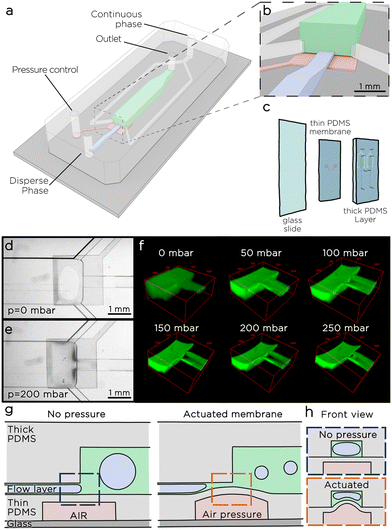
The microfluidic tuna-step system consists of a two-layer PDMS chip – as two layers are needed for an on-chip microvalve to function20–22 – bonded to a common glass slide (Fig. 1a–c). The top layer, referred to as the thick layer, comprises a narrow channel that serves as the inlet for the dispersed phase. This channel directs the liquid to a spacious emulsification chamber. Additionally, two side channels enable a continuous flow of the continuous phases from the sides of the nozzle. The emulsification channel culminates in the chip outlet, facilitating the collection of the emulsion.The middle layer, known as the thin layer, features a square chamber situated below the step-emulsification nozzle. A thin membrane, approximately 50 μm in thickness, separates this chamber from the nozzle. When pressure is applied to the chamber, the thin membrane undergoes deflection, causing a reduction in the size of the nozzle (Fig. 1e and f). To better investigate the effect of membrane deflection over the step size, we introduced a water solution of a fluorescently-labelled polymer (gelatin-FITC) into the chip and conducted a fluorescence scan along the chamber using a confocal microscope (Fig. 1f). As expected, the membrane deflects, resulting in a significant decrease in the nozzle size. Once the applied pressure (Pm) exceeds 50 mbar, the thin membrane, which in the central part of the step deforms the most, comes in contact with the opposite nozzle wall. Under these conditions, two streams of liquid emerge at the sides of the step, we call those streams side nozzles. As the pressure continues to increase, the cross-sectional area of the two side nozzles decreases. When the pressure is released, the elastic membrane returns to its initial configuration.
We tested the membrane actuation switching Pm between 0 and 300 mbar every 5 seconds for more than 24 hours, and recorded the results in a time-lapse video that did not show visible changes in more than 8600 consequent actuations. We tested the limits of the membrane applying a pressure increase of 100 mbar every 10 seconds until the membrane would break, and observed the maximum pressure in a range between 1900 and 3000 mbar, consistently higher than the pressure range used for the droplet generation.
2.2 Characterization of tuna-step for the generation of water-in-oil emulsions
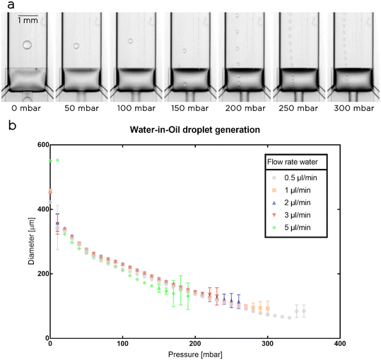
As initial experiments, we used a single nozzle chip to generate water droplets in a solution of fluorinated oil and surfactants (Novec 7500 oil with 2% w/t PFPE-PEG-PFPE surfactant23) and measured the diameter of the water droplets (Fig. 2). Both phases were supplied to the microfluidic system using precision syringe pumps while the membrane was actuated using a pressure controller. We fixed the flow rate for the oil at 1 μl min−1 and set the flow rate for the aqueous phase at 0.5, 1, 2, 3, and 5 μl min−1. For each set of flow rates, we monitored the effects of the actuatable membrane on droplet generation for a range of pressures (Pm) starting from 0 mbar and increasing with 10 mbar steps. In each experiment, Pm was increased until the system stopped operating smoothly. The maximum pressure applied to the membrane depended on the droplet flow rate used, with an inversely proportional trend between the two variables: the higher the droplet flow rate, the lower the maximum Pm that can be used to generate droplet in a stable and reliable manner.For Pm = 0 mbar, as expected, the generated droplets reached their maximum volume as the step size was at a maximum. Interestingly, we observed that during droplet generation the membrane was partially deflected downward and, in some cases depending on the droplet flow rate used, touched the glass slide. In these cases (e.g. at 5 μl per minute) we observed a slightly larger droplet diameter due to the increases in nozzle height and flow rate, but the droplet generation remained stable. At Pm = 10 mbar, the applied pressure lacks the necessary strength to consistently deform the membrane and the droplets formed at this pressure have inconsistent sizes (see larger error bars in Fig. 2b). At 20 mbar and higher pressures, the droplet generation became reliable, with an increase of Pm resulting in a consistent decrease in nozzle and droplet sizes (Fig. 2b). Based on the explored operational ranges, we obtained a dynamic control over droplet size between 64 ± 4 μm and 551 ± 2 μm corresponding to a volume range between 140 ± 30 pl and 88 ± 1 nl.
2.3 PDMS hydrophilic surface modification for prolonged oil-in-water emulsion generation
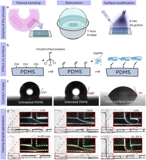
Following the preliminary characterization, we decided to explore the possibility to produce O/W emulsions with tuna-step chips. This required satisfying two essential conditions: i) the inner surface of the microfluidic channels must be hydrophilic to ensure the proper sliding of the oil droplets generated after the step, and ii) the chip must be impermeable towards the oil phase (most of the organic solvents and oils quickly swell PDMS).24To address these two requirements, we developed an innovative surface modification that promotes both a hydrophilic surface and prevents the PDMS swelling due to the oil phase, enabling long-time emulsion production. The surface modification consists of two simple steps, realized directly after the standard plasma bonding25 of the chip (Fig. 3a): i) coating the microchannels with vinyltrichlorosilane and ii) flushing, under UV light, the treated chip with a gelatin-methacryloyl (GelMA) water solution containing a photoinitiator to chemically bond GelMA polymer chains to the vinyl moieties previously introduced onto PDMS surface.
To confirm the validity and the stability of our surface modification, we measured both the water contact angle and the generation of O/W emulsions after each step of the protocol using a standard T-junction (Fig. 3c, after plasma bonding, after silanization and after GelMA treatment). As shown in Fig. 3c the contact angle of untreated PDMS was 117°; after silanization with vinyltrichlorosilane, the value decreased to 108°, while the one of the GelMA-treated PDMS was 71°, confirming the hydrophilicity of the PDMS surface. To generate O/W emulsions, we used hexadecane as droplet phase and recorded time-lapse videos over a period of up to 24 h. While the droplet generation remained stable in the surface-modified chip for the whole studied period (24 consecutive hours of emulsion generation), the other two chips (plasma bonded only, plasma bonded and silanized) presented visible swelling of the PDMS channels already after 30 minutes (Fig. 3d). We proved the long-term stability of the surface modification by using the same chip to generate droplets reliably after more than 3 months from the surface modification.
2.4 Characterization of oil-in-water emulsions in surface-modified tuna-step
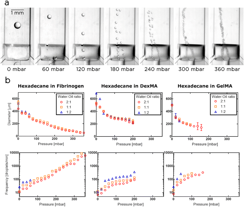
Since our ultimate goal was to use the tuna-system as a printing head for the synthesis of porous hydrogels, we calibrated and characterized the surface-modified chips using as aqueous phases various biopolymer solutions, containing dextran methacrylate (DexMA), Gelatin-methacryloyl (GelMA) or fibrinogen. For the disperse phase, we selected hexadecane. In these experiments, we fixed the flow rate of the aqueous phase at 1 μl min−1 and tuned the oil flow at 0.5, 1 and 2 μl min−1, thus generating emulsions having droplet volume fractions of 33%, 50% and 66% respectively.Similarly to the case of W/O emulsions, for each tested aqueous phase, the volume of the droplets reached the maximum value when the membrane was not actuated, while an increase in Pm resulted in a decrease in nozzle and droplet sizes. We observed that the droplets are initially generated in the center of the nozzle, but as soon as we increase Pm, they give priority to one side of the actuated nozzle. In these cases, we noticed that the “preferred” side can be selected by slightly tilting the chip. When the pressure was increased further, the membrane effectively transformed the step geometry, creating two side nozzles (Fig. 4a). Then, the droplets started being generated in parallel in the two side nozzles, until a critical pressure was applied to the membrane and the process of droplet generation became chaotic. For the tested aqueous phases, the dynamic ranges of the droplet sizes obtained were as follows (Fig. 4b): i) the droplets in the fibrinogen solution ranged between 54 and 538 μm in diameter, corresponding to a volume range between 82 pl and 82 nl; ii) the droplets in the DexMA solution had a diameter ranging between 218 and 688 μm, corresponding to a volume range between 5 and 170 nl; iii) the droplets in the GelMA solution varied between 143 and 518 μm, corresponding to a volume range between 1.5 and 73 nl. The fibrinogen solution generated droplets in the widest pressure range, up to 360 mbar, and produced droplets in the widest range of volumes (3 orders of magnitude). However, we selected DexMA for the following experiments (i.e. the synthesis of our porous hydrogels) as, compared to the other two biopolymers, it can be easily and rapidly photopolymerized and the resulting gels offer better stability and mechanical response.26,27
2.5 3D printing of porous functionally graded hydrogels (pFGhs) with tuna-step
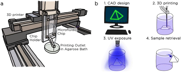
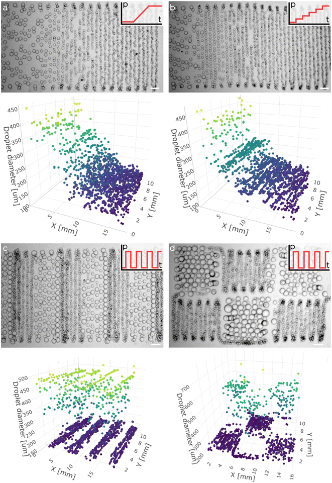
To finally 3D print porous functionally graded hydrogels, we mounted the tuna-step chip on a custom 3D printer (Fig. 5a). The printing process was executed within an agarose fluid-gel bath that acted as a support material during emulsion extrusion. As demonstrated recently, the use of such fluid-gel bath is convenient as, from the one hand, allows the 3D printing of more complex architectures and, from the other one, it enables the decoupling of printing resolution from the rheological properties of the extruded emulsion (Fig. 5b).First, we tested our ability to extrude the O/W emulsion inside the agarose bath. To have a clear view over the position and size of the deposited droplets, we printed various 2.5D emulsion patterns using different pressure profiles for the membrane actuation (Fig. 6). Moreover, we demonstrated that the pressure profile could be synchronized precisely with the robotic motion control, generating complex spatial emulsion patterns (see for instance the chess spatial organization of small and big droplets). Fig. 6c and d demonstrate the synchronization of a square-function pressure profile with two distinct printing paths (serpentine and chess-like motion) with the scope of highlighting the wide array of spatial structures that can be achieved by finely adjusting the pressure profiles in relation to the spatial deposition.
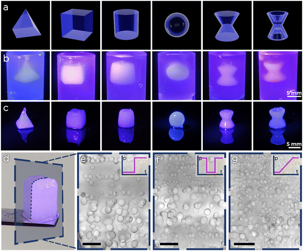
After achieving full synchronization between emulsion generation and spatial deposition within a layer, we tested our platform for the synthesis of macroscopic pFGhs. We selected six different geometries with various degrees of structural complexity and 3D printed them in the agarose support bath using, for convenience, an O/W emulsion having 20% of oil volume fraction. As shown in Fig. 7, all structures were finely printed with minor discrepancies between the CAD model and the actual 3D shape. Moreover, we printed pFGhs while changing the pressure profiles during extrusion, to observe the change in porosity. After printing and exposing the samples to UV light, we removed the pFGhs from the agarose bath (e.g. the one in Fig. 7d), we sectioned them with a scalpel and observed them at the microscope. In Fig. 7e–g we show slices from three different pFGhs where the changes in pore size from the bottom to the top of the slice give a qualitative demonstration of the effect of three pressure profiles (respectively on–off, alternate and gradient pressure profiles).
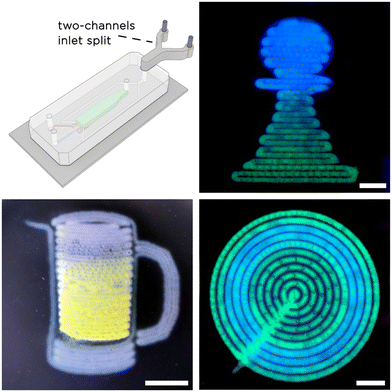
Finally, to additionally prove the possibility of printing multi-material O/W emulsions with tuna-step, we added a Y-junction connector to the continuous phase inlet to process two different solutions. To better appreciate the spatial localization of the two materials within the printed O/W emulsions, we prepared two DexMA solutions containing a few mg ml−1 of fluorescent dyes. In this case, we supplied the two continuous phases to tuna-step using different flow profiles and processed them in the form of complex 2.5D patterns (chess pawn, concentric circles and a mug of beer). The results are shown in Fig. 8.
2.6 Parallelization of the tuna-step nozzle to increase emulsion throughput
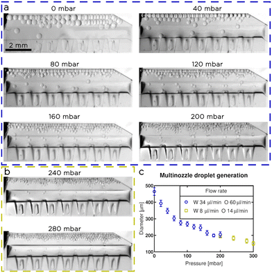
To show that tuna-step is comparable in terms of throughput to flow focusing modules, we designed a microfluidic chip consisting of 14 parallel nozzles, with input from a single liquid source, aligned on top of a wide membrane (Fig. 9). The inlet channel had a 400 μm height, and was connected to the nozzles (100 μm height) through linear slopes.28 We incorporated the slopes to ensure a seamless transition from the inlet channel to the emulsifying nozzles while maintaining a significantly higher hydrodynamic resistance within the nozzles compared to the inlet channel. This design requirement is crucial to ensure a balanced flow rate for each nozzle, promoting uniformity in the emulsification process.We calibrated and tested the multi-nozzle tuna-step chip to generate water droplets in NOVEC 7500 oil (with 2% w/t surfactant). We applied a constant flowrate of 60 μl min−1 for the oil phase and 34 μl min−1 for the water (Fig. 9a). We applied increasing pressures to the actuatable membrane with steps of 20 mbar, until we reach 200 mbar. After that, the droplet generation became unstable, so, based on the results obtained with single-nozzle chips, we decreased the flow rates to 14 μl min−1 for the oil and 8 μl min−1 for the water (Fig. 9b); then, we increased again the pressure until we reach 300 mbar. We observed a gradual decrease in droplet size, with a range of diameters between 150 ± 10 μm and 460 ± 20 μm, corresponding to a volume range between 1.8 ± 0.4 nl and 51 ± 7 nl (Fig. 9c).
3. Discussion
Here we reported tuna-step, a droplet generation strategy based on a microfluidic step emulsification nozzle coupled with a flexible membrane for production of droplets of dynamically controllable sizes. By actuating the membrane beneath the step, we can control the nozzle lumen and thus control the size of generated droplets without changing the liquid input flow rates. Tuna-step combines advantages of flow focusing modules (controllable droplet volumes) and of step emulsification modules (constant input liquid flow rates, high volume fraction of obtained emulsions).The working principle behind droplet generation in a step has been widely studied,5,6,9,10,28,29 and its correlation with the nozzle height is well known. In this configuration, the droplet size depends mostly on the nozzle size, resulting in the robust generation of highly monodisperse emulsions. However, when droplets of different sizes are necessary – as in the case of microfluidic-assisted 3D printing of pFGMs – conventional step emulsification systems are limited.
Lian et al.30 reported one innovative solution to overcome the fixed droplet size in step emulsification by integrating a co-flow module at the nozzle outlet. Despite being a creative approach to extend the capabilities of step emulsification, it came with the drawbacks of co-flow systems, such as i) relying on changes of flow rates to modify the droplet sizes and ii) the challenging parallelization that would require separate channels of continuous phase for each nozzle. Conversely, our device relied on tuning the emulsifying nozzle, allowing to change the droplet size even while maintaining the constant flow rates, and not excluding parallelization.
Lin et al.31 previously reported the change in droplet size obtained by using membranes as valves that could be closed and then opened completely. Their approach to actively control the droplet volumes can be compared to the droplets-on-demand methods,15 and therefore is consistently different from our system, where we modify the nozzle geometry and keep the nozzle modified over time. The droplet splitting in our tunable nozzle occurs without closing the valve completely, dramatically improving the throughput of our system over the approach of Lin et al. that was optimized to generate double emulsions.
In the recent past, droplet size gradients in emulsions or foams were achieved in valve-based flow focusing systems;32,33 however the strong dependence of flow-focusing geometries on the flow rate makes it challenging to parallelize them to increase the throughput. In contrast, the parallelization of step emulsification devices has been widely implemented for different high-throughput applications.8,9 Here, we demonstrated that the tuna-step geometry can be easily parallelized to generate droplets of controllable volume at a higher throughput, with potential for further upscaling. By multiplying the nozzles to 14, we generated W/O droplets at 130 Hz. Notably, the use of PDMS for chip manufacturing did not represent a major problem and both O/W and W/O emulsions could be generated in the proposed devices. We anticipate further studies that will parallelize the design we showed, exploiting the use of our technology for the high-throughput generation of droplets with a controllable size that could be implemented in other research areas beyond porous material synthesis. Based on our design, it is possible to engineer a highly parallelized chip for a high-throughput generation of monodisperse droplets with a diameter that is controlled only by the deflection and change of the geometry of the nozzle. Nevertheless, engineering such a design is not an obvious task. In fact, there are a few aspects that should be carefully addressed. First, it is necessary to ensure similar resistance through all the nozzles, otherwise the flow will prioritize those having less resistance, and the emulsification will not be consistent or parallelized. Second, a higher number of nozzles would require larger membranes, that can easily bond with the glass surface during chip manufacturing. This problem could be solved with the different design of the membrane or with a chip design that considers alternative materials, for example with an elastic thermoplastic membrane instead of a PDMS membrane. Third, the outlet of the chip should be designed carefully to facilitate the droplet escape from the nozzles. At high throughput and high rate of droplet generation, improper outlet design might trap the generated droplets in the chip, and thus destabilize droplet production in the long run.
Another characteristic aspect of our system is that the actuation of tuna-step at high enough pressures forces formation of droplets in two places, effectively forming a double-nozzle from each tuna-step nozzle. We hypothesize that there might be possibly an interplay between the two “sub-nozzles” during droplet generation; however, the potential differences in droplet sizes generated in the two sub-nozzles are not large enough to increase the overall emulsion polydispersity. We have reported before a step emulsification with a nozzle that was divided into two sub-nozzles by a solid obstacle in the middle of the nozzle.23 Such geometry generated droplets for different flow rates keeping the size constant, and the design was considerably different from the one reported in this work. In this paper, even when the membrane acts as an obstacle in the middle of the nozzle, it constitutes a flexible part that is changing dynamically in function of the overall pressure. The result is a series of monodisperse droplets with a size that depends on the pressure on the membrane layer.
As reported by Unger et al.,20 the response of the valve to pressure actuation can be adjusted by changing the membrane thickness. In our study, we used a membrane with a thickness of ∼50 μm, allowing a reasonable pressure range in relation to the membrane deflection. A thinner membrane would be deflected with a lower pressure range, obtaining a coarse tuning in size. A thicker membrane would require higher pressures for actuation, that could damage the chip or temporarily deform the structures in the thick layer (we already observed that the nozzles in the thick layer are subject to deformation when we applied higher pressures). In the future, one could easily tune the Young modulus of PDMS to obtain more or less flexible structures, by changing the ratio between the polymer and the curing agent, or could adopt different materials. With PDMS being one of the widest adopted materials in microfluidics, the PDMS-based technology that we developed should be easily accessible to other researchers.
In this study, we aimed at using the developed tuna-step in combination with 3D printing to manufacture porous biocompatible hydrogels. In this case, the use of a hydrophilic continuous phase required the PDMS microfluidic chip to be hydrophilic. To accomplish this, we developed a novel hydrophilic surface modification. Notably, our surface treatment was particularly stable and durable, enabling us to use the same chip several times without repeating the modification. We coupled our chip with a custom 3D printer, and we deposited the emulsion in a supporting agarose bath. During the emulsion deposition, we applied different pressure profiles to the membrane, generating tunable emulsions. By synchronizing the mechanical motion with the emulsion production, we showed that one can create sophisticated 2.5D and 3D droplet patterns which after the crosslinking of the continuous phase, will represent the porous template. Of note, we adapted the inlet of the chip to use two different materials for the outer phase, showing evidence of multi-material printing of pFGhs. In the future, some efforts should be spent to further optimize the tuna-step design and fabricate pFGhs within even wider operational ranges. In particular, the control over the volume fraction of the dispersed phase should be improved. This parameter, in fact, is primary responsible for the porosity of the fabricated material, a feature that is often desirable to tune in wide ranges to tailor, for instance, the sample mechanical properties. At the moment, our design operates properly up to a droplet volume fraction of 60%. Above this value, the steps are crowded with droplets and droplet generation becomes inconsistent. A possible solution that could be adopted consists in the use of draining channels in the chip outlet for partially removing the excess of continuous phase.34,35
We showed that tuna-step is a valid droplet generation strategy, and that it could benefit from some developments in the future. The most important are large-scale parallelization of nozzles, and development of tuna-step in materials that are easier to produce at mass scale than PDMS, like thermoplastics.
4. Conclusions
In this study, we introduced tuna-step, an innovative droplet microfluidic system that overcomes a key limitation of step emulsification: fixed droplet size. Utilizing tuna-step, we successfully generated droplets of varying sizes and compositions using a step-emulsifying nozzle. Our dynamic step emulsifier enabled us to produce emulsions with gradient droplet sizes. We extensively characterized our device at different flow rates to determine the operational range for oil-in-water and water-in-oil emulsions. By adjusting the pressure on the tuna-step membrane, we achieved consistent reduction in droplet size across the tested flow rates. To facilitate the generation of oil-in-water emulsions, we developed a custom hydrophilic surface modification that prevented PDMS swelling with hexadecane oil. With this modification, we were able to continuously produce oil-in-water droplets for over 24 hours. We leveraged our technology to 3D print functionally graded materials, incorporating changes in porosity and material composition. By placing the chip on a custom 3D printer, extruding the emulsion into an agarose gel support bath, and exposing it to UV light for polymerization, we obtained self-sustaining 3D structures after removing the porous material from the bath. Our study not only demonstrates the suitability of our tuna-step design for 3D emulsion printing and materials science but also opens up possibilities for a wide range of future applications. This consideration is supported by the preliminary results obtained in the parallelization of the tuna-step geometry, where we produced custom emulsions from 14-nozzles working simultaneously.Looking ahead, we envision further parallelization of the presented systems, enabling high-throughput emulsion generation with active control over droplet size, regardless of flow rate or volume fraction.
5. Materials and methods
5.1 Design of tuna-step microfluidic chip
We realized a two-layer PDMS chip replicating the on-chip valve technology20 and adapted the design to overlap the thin PDMS membrane with the nozzle for step emulsification, as shown in Fig. 1.The chip consists of two PDMS layers bonded on a 1 mm thick glass slide. The layer in contact with the glass slide is thin (100 μm), and it includes the chips membrane and one inlet to access the source for pressurized air. The layer on top is thick (5 mm), and it includes one inlet for the disperse phase, one for the continuous phase, and one outlet for the definitive collection of the droplets.
5.2 Master preparation
We realized the scheme of the chip using CAD (Autodesk AutoCAD) and used different approaches to produce the masters for the two separate layers. 1) Thin layer: we prepared the master with standard photolithography.36 We coated a 7′′ silicon wafer with a few ml of SU8-2050 and performed the spin-coating for 30 s at 3000 rpm. We soft-baked the chip for 1 minute at 65 °C and then 6 minutes at 95 °C. We exposed the chip for 19 s and performed the post-exposure baking (1 minute at 65 °C and then 5 minutes at 95 °C). We immersed the wafer in SU8-developer for 5 minutes to remove the unexposed resist and rinsed the chip with isopropanol. We air-dried the chip and performed the hard baking at 200 °C for 5 minutes, and then we let the wafer cool down to room temperature. We silanized the wafer to prevent PDMS adhesion: we put the wafer in a vacuum chamber with two test tubes containing 30 μl of trichloro(1H,1H,2H,2H-perfluorooctyl)silane (Sigma Aldrich, USA), and activated the pump for 45 minutes at 10 mbar. 2) Thick layer: we prepared the master by CNC milling on 5 mm polycarbonate plates (described below).5.3 Chip preparation
1) Thin layer: we deposed the thin layer with a spin-coater: we covered the center of the chip with a few drops of uncured PDMS (10![[thin space (1/6-em)]](https://www.rsc.org/images/entities/char_2009.gif) :
:![[thin space (1/6-em)]](https://www.rsc.org/images/entities/char_2009.gif) 1 ratio between the PDMS and the crosslinking agent). We controlled the thin layer thickness by adjusting the speed of the spin-coater (1500 rpm for 30 s) and the time after mixing PDMS with its curing agent (3 h waiting time). We oven-baked the thin layer for 2 hours at 75 °C. We obtained thin PDMS layers with a ∼100 μm thickness. The channel depth in the thin layer was ∼50 μm, hence the thin membrane below the step had thickness ∼50 μm. 2) Thick layer: we prepared the master by CNC milling on 5 mm polycarbonate plates. We replicated the chip by coating the milled polycarbonate plates with PDMS and baking it for 2 hours at 75 °C. We then silanized the negative mold to prevent adhesion and repeated the procedure to obtain the positive replica. We baked it for 2 hours at 75 °C and finally removed the thick layer from the mold. We punched the inlets and outlets for the flow layer. 3) PDMS on PDMS bonding: we poured a few drops of curing agent on a clean silicon wafer and spin-coated it at 5500 rpm for 45 s to obtain a thin, uniform coating. We positioned the thick PDMS layer on the wafer, ensuring that the surface was lightly coated with the curing agent. Following the markers on the thin layer, we placed a homemade frame on the thin layer to align the two layers, and then we inserted the thick layer within the frame, carefully removing the bubbles. We baked the chip overnight at 75 °C, then slowly peeled away the thin layer from the silicon master, leaving two bonded PDMS layers. We punched the hole for the thin membrane inlet and sealed the chip with the glass slide via standard plasma bonding. After bonding, we baked the chip for 10 minutes at 75 °C to help the adhesion of the PDMS on the glass.
1 ratio between the PDMS and the crosslinking agent). We controlled the thin layer thickness by adjusting the speed of the spin-coater (1500 rpm for 30 s) and the time after mixing PDMS with its curing agent (3 h waiting time). We oven-baked the thin layer for 2 hours at 75 °C. We obtained thin PDMS layers with a ∼100 μm thickness. The channel depth in the thin layer was ∼50 μm, hence the thin membrane below the step had thickness ∼50 μm. 2) Thick layer: we prepared the master by CNC milling on 5 mm polycarbonate plates. We replicated the chip by coating the milled polycarbonate plates with PDMS and baking it for 2 hours at 75 °C. We then silanized the negative mold to prevent adhesion and repeated the procedure to obtain the positive replica. We baked it for 2 hours at 75 °C and finally removed the thick layer from the mold. We punched the inlets and outlets for the flow layer. 3) PDMS on PDMS bonding: we poured a few drops of curing agent on a clean silicon wafer and spin-coated it at 5500 rpm for 45 s to obtain a thin, uniform coating. We positioned the thick PDMS layer on the wafer, ensuring that the surface was lightly coated with the curing agent. Following the markers on the thin layer, we placed a homemade frame on the thin layer to align the two layers, and then we inserted the thick layer within the frame, carefully removing the bubbles. We baked the chip overnight at 75 °C, then slowly peeled away the thin layer from the silicon master, leaving two bonded PDMS layers. We punched the hole for the thin membrane inlet and sealed the chip with the glass slide via standard plasma bonding. After bonding, we baked the chip for 10 minutes at 75 °C to help the adhesion of the PDMS on the glass.
5.4 Hydrophobic surface modification
Following the bonding process, we flushed the channels with a 5% w/t solution of silane (trichloro(1H,1H,2H,2H-perfluorooctyl)silane, Sigma Aldrich, USA), in fluorinated oil (NOVEC 7500, 3 M, USA). We carefully avoided applying excessive pressure that could result in the membrane coming into contact with the glass slide, rendering it unusable.5.5 Water-in-oil droplet generation
We filled one glass syringe (Hamilton gastight) with water and one with oil (Novec 7500 oil with 2% w/t PFPE–PEG–PFPE surfactant, synthetized according to the protocol described by Holtze et al.37). Each syringe is connected to a 0.5 mm O.D. steel needle and then to the inlet of the chip through a Teflon tubing (0.8 mm O.D., 0.5 mm I.D.). We controlled the flowrates with precision syringe pumps (neMESYS, Cetoni) with the related software (neMESYS user interface).We controlled the pressure in the thin layer with a pressure controller (OB1-MK3+, Elveflow), generating stationary pressure gradients or alternated pressure curves with the related software.
5.6 Hydrophilic surface modification
Immediately after the bonding, we put the chip in the vacuum chamber with a test tube containing 30 ml of vinyltrichlorosilane. We activated the vacuum pump for 1 hour at 5 mbar. We removed the chip from the vacuum chamber and flushed the channels with a 1% w/t solution of gelatin-methacryloyl (GelMA) in water at a constant flow rate of 20 μl min−1. During this process, we shine UV light on the chip, activating the bonding between GelMA polymers and the previously introduced vinyltrichlorosilane. Finally, we rinsed the chip with distilled water to remove the GelMA solution.5.7 Generation of oil-in-water droplets
We generated droplets of hexadecane in three different aqueous solutions. We prepared new batches of aqueous solutions shortly before every experiment to avoid contamination of the reagents or photoinitiation of the DexMA solution. GelMA solution: we prepared a 0.5% w/t solution of Plantacare in water and then solved GelMA to form a 3% w/v solution. DexMA solution: we prepared a 0.5% w/t solution of Plantacare in water, and then solved DexMA to form a 20% w/v solution. We prepared a 100 mg ml−1 solution of Irgacure in a 70% w/t solution of ethanol in water, that we used as initiator with a 100× dilution. Fibrinogen solution: we prepared a 1.4% w/t solution of fibrinogen in 0.5% w/t solution of Plantacare in water.5.8 3D printing in agarose fluid gel
We prepared the bath of agarose fluid gel adding 0.5% w/t agarose in water. We autoclaved the solution at 121 °C for 20 minutes to sterilize and melt the agarose solution, and then we stirred the solution overnight at 700 rpm. With the gradual decrease in temperature, agarose gel microparticles form, and at room temperature, we obtain an agarose fluid gel (as previously reported38).We stored the oil and aqueous phases in glass syringes and controlled the flow with syringe pumps, as described before.
We secured the chip to the z-axis of the XYZ robotic gantry system in a vertical position to favour droplet escape from the step nozzle using a custom-made polycarbonate holder that was equipped with a 25G metallic needle for precise emulsion deposition (Fig. 5a).
The printing process consists of five steps: i) we design the 3D model of the object with computer-aided design (CAD, Autodesk Inventor) ii) we use free software (Slic3r) to convert the CAD file into a file containing the instructions for the XYZ movements of the printer stage (G-code file). We performed the automated slicing of the 3D object considering a printing nozzle with a 0.5 mm diameter and a slice thickness of 0.2 mm. iii) We generated an emulsion of hexadecane droplets in DexMA solution and extruded the emulsion in the agarose bath. During this step, the motorized stage follows the instructions of the G-code file, depositing the emulsion within the agarose bath (Fig. 6a). iv) Following the extrusion, we exposed the emulsion to UV light (λ = 365 nm) for 5 minutes, triggering the crosslinking of the material (Fig. 6b). v) After the polymerization, we extracted the 3D structures from the bath, rinsed them with water, and proved their stability (Fig. 6c).
Author contributions
Francesco Nalin: conceptualization, data curation, formal analysis, investigation, methodology, visualization, original draft preparation, review & editing. Maria Celeste Tirelli: investigation, review & editing. Piotr Garstecki: funding acquisition, project administration, resources, supervision, review & editing. Witold Postek: conceptualization, supervision, review & editing. Marco Costantini: conceptualization, funding acquisition, methodology, project administration, resources, supervision, visualization, review & editing.Conflicts of interest
There are no conflicts to declare.Acknowledgements
This article is part of a project that has received funding from the European Union's Horizon 2020 research and innovation programme under the Marie Skłodowska-Curie grant agreement no 813786 (EVOdrops). M. C. and M. C. T. acknowledge the funding from the National Science Centre Poland (NCN) within OPUS 19 project no. 2020/37/B/ST8/02167. W. P. was supported by the Polish National Agency for Academic Exchange (NAWA) through the Bekker Programme, grant no. PPN/BEK/2020/1/00333/U/00001. W. P. was supported by the Foundation for Polish Science (FNP) with the START 069.2021 scholarship. P. G. acknowledges the support from the National Science Centre, Poland, funding based on decision 2018/30/A/ST4/00036, Maestro 10.References
- S. Mashaghi, A. Abbaspourrad, D. A. Weitz and A. M. van Oijen, Droplet microfluidics: A tool for biology, chemistry and nanotechnology, TrAC, Trends Anal. Chem., 2016, 82, 118–125 CrossRef CAS.
- A. Van Den Berg, H. Craighead, P. Yang, S. Marre and K. F. Jensen, Synthesis of micro and nanostructures in microfluidic systems, Chem. Soc. Rev., 2010, 39(3), 1183–1202 RSC.
- A. Suea-Ngam, P. D. Howes, M. Srisa-Art and A. J. Demello, Droplet microfluidics: from proof-of-concept to real-world utility?, Chem. Commun., 2019, 55(67), 9895–9903 RSC.
- S. Neethirajan, I. Kobayashi, M. Nakajima, D. Wu, S. Nandagopal and F. Lin, Microfluidics for food, agriculture and biosystems industries, Lab Chip, 2011, 11(9), 1574–1586 RSC.
- A. Montessori, M. Lauricella, S. Succi, E. Stolovicki and D. Weitz, Elucidating the mechanism of step emulsification, Phys. Rev. Fluids, 2018, 7(3), 1–7 Search PubMed.
- R. Dangla, E. Fradet, Y. Lopez and C. N. Baroud, The physical mechanisms of step emulsification, J. Phys. D: Appl. Phys., 2013, 46(11), 114003 CrossRef.
- N. Mittal, C. Cohen, J. Bibette and N. Bremond, Dynamics of step-emulsification: From a single to a collection of emulsion droplet generators, Phys. Fluids, 2014, 26(8), 082109 CrossRef.
- J. M. de Rutte, J. Koh and D. Di Carlo, Scalable High-Throughput Production of Modular Microgels for In Situ Assembly of Microporous Tissue Scaffolds, Adv. Funct. Mater., 2019, 29(25), 1900071 CrossRef.
- E. Amstad, M. Chemama, M. Eggersdorfer, L. R. Arriaga, M. P. Brenner and D. A. Weitz, Robust scalable high throughput production of monodisperse drops, Lab Chip, 2016, 16(21), 4163–4172 RSC , Available from: https://pubs.rsc.org/en/content/articlehtml/2016/lc/c6lc01075j.
- A. Montessori, M. Lauricella, E. Stolovicki, D. A. Weitz and S. Succi, Jetting to dripping transition: Critical aspect ratio in step emulsifiers, Phys. Fluids, 2019, 31(2), 021703 CrossRef.
- P. Garstecki, H. A. Stone and G. M. Whitesides, Mechanism for flow-rate controlled breakup in confined geometries: A route to monodisperse emulsions, Phys. Rev. Lett., 2005, 94(16), 164501 CrossRef PubMed.
- P. Garstecki, M. J. Fuerstman, H. A. Stone and G. M. Whitesides, Formation of droplets and bubbles in a microfluidic T-junction—scaling and mechanism of break-up, Lab Chip, 2006, 6(3), 437–446 RSC.
- P. Guillot, A. Colin, A. S. Utada and A. Ajdari, Stability of a jet in confined pressure-driven biphasic flows at low reynolds numbers, Phys. Rev. Lett., 2007, 99(10), 104502 CrossRef.
- A. Dewandre, J. Rivero-Rodriguez, Y. Vitry, B. Sobac and B. Scheid, Microfluidic droplet generation based on non-embedded co-flow-focusing using 3D printed nozzle, Sci. Rep., 2020, 10(1), 1–17 CrossRef PubMed.
- K. Churski, P. Korczyk and P. Garstecki, High-throughput automated droplet microfluidic system for screening of reaction conditions, Lab Chip, 2010, 10(7), 816–818 RSC.
- M. Marcotulli, M. C. Tirelli, M. Volpi, J. Jaroszewicz, C. Scognamiglio and P. Kasprzycki, et al., Microfluidic 3D Printing of Emulsion Ink for Engineering Porous Functionally Graded Materials, Adv. Mater. Technol., 2022, 2201244 Search PubMed.
- M. Costantini, J. Jaroszewicz, Ł. Kozoń, K. Szlązak, W. Święszkowski and P. Garstecki, et al., 3D-Printing of Functionally Graded Porous Materials Using On-Demand Reconfigurable Microfluidics, Angew. Chem., Int. Ed., 2019, 58(23), 7620–7625 CrossRef CAS PubMed.
- G. Cidonio, M. Costantini, F. Pierini, C. Scognamiglio, T. Agarwal and A. Barbetta, 3D printing of biphasic inks: beyond single-scale architectural control, J. Mater. Chem. C, 2021, 9(37), 12489–12508 RSC.
- J. Elsing, A. Quell and C. Stubenrauch, Toward Functionally Graded Polymer Foams Using Microfluidics, Adv. Eng. Mater., 2017, 19(8), 1700195 CrossRef.
- M. A. Unger, H. P. Chou, T. Thorsen, A. Scherer and S. R. Quake, Monolithic microfabricated valves and pumps by multilayer soft lithography, Science, 2000, 288(5463), 113–116 CrossRef CAS PubMed.
- T. Thorsen, S. J. Maerkl and S. R. Quake, Microfluidic large-scale integration, Science, 2002, 298(5593), 580–584 CrossRef CAS PubMed.
- Y. S. Lee, N. Bhattacharjee and A. Folch, 3D-printed Quake-style microvalves and micropumps, Lab Chip, 2018, 18(8), 1207–1214 RSC.
- W. Postek, P. Gargulinski, O. Scheler, T. S. Kaminski and P. Garstecki, Microfluidic screening of antibiotic susceptibility at a single-cell level shows the inoculum effect of cefotaxime on: E. coli, Lab Chip, 2018, 18(23), 3668–3677, 10.1039/C8LC00916C.
- R. Dangla, F. Gallaire and C. N. Baroud, Microchannel deformations due to solvent-induced PDMS swelling, Lab Chip, 2010, 10(21), 2972–2978 RSC.
- Y. Xia and G. M. Whitesides, Soft Lithography, Angew. Chem., Int. Ed., 1998, 37(5), 550–575 CrossRef CAS PubMed.
- M. C. McManus, E. D. Boland, H. P. Koo, C. P. Barnes, K. J. Pawlowski and G. E. Wnek, et al., Mechanical properties of electrospun fibrinogen structures, Acta Biomater., 2006, 2(1), 19–28 CrossRef PubMed.
- D. L. Matera, W. Y. Wang, M. R. Smith, A. Shikanov and B. M. Baker, Fiber Density Modulates Cell Spreading in 3D Interstitial Matrix Mimetics, ACS Biomater. Sci. Eng., 2019, 5(6), 2965–2975 CrossRef CAS PubMed.
- W. Postek, T. S. Kaminski and P. Garstecki, A passive microfluidic system based on step emulsification allows the generation of libraries of nanoliter-sized droplets from microliter droplets of varying and known concentrations of a sample, Lab Chip, 2017, 17(7), 1323–1331 RSC.
- Y. T. Kao, T. S. Kaminski, W. Postek, J. Guzowski, K. Makuch and A. Ruszczak, et al., Gravity-driven microfluidic assay for digital enumeration of bacteria and for antibiotic susceptibility testing, Lab Chip, 2019, 20(1), 54–63 RSC.
- J. Lian, X. Luo, X. Huang, Y. Wang, Z. Xu and X. Ruan, Investigation of microfluidic co-flow effects on step emulsification: Interfacial tension and flow velocities, Colloids Surf., A, 2019, 568, 381–390 CrossRef CAS.
- H. H. Lin, S. C. Chang and Y. C. Su, On-demand double emulsification utilizing pneumatically actuated, selectively surface-modified PDMS micro-devices, Microfluid. Nanofluid., 2010, 9, 1091–1102 CrossRef CAS.
- A. R. Abate, M. B. Romanowsky, J. J. Agresti and D. A. Weitz, Valve-based flow focusing for drop formation, Appl. Phys. Lett., 2009, 94(2), 023503 CrossRef.
- M. Costantini, J. Jaroszewicz, Ł. Kozoń, K. Szlązak, W. Święszkowski and P. Garstecki, et al., 3D-Printing of Functionally Graded Porous Materials Using On-Demand Reconfigurable Microfluidics, Angew. Chem., Int. Ed., 2019, 58(23), 7620–7625 CrossRef CAS PubMed.
- R. D. Sochol, M. E. Dueck, S. Li, L. P. Lee and L. Lin, Hydrodynamic resettability for a microfluidic particulate-based arraying system, Lab Chip, 2012, 12(23), 5051–5056 RSC.
- J. R. Haliburton, S. C. Kim, I. C. Clark, R. A. Sperling, D. A. Weitz and A. R. Abate, Efficient extraction of oil from droplet microfluidic emulsions, Biomicrofluidics, 2017, 11(3), 34111 CrossRef CAS.
- P. M. Winter, G. M. Lanza, S. A. Wickline, M. Madou, C. Wang and P. B. Deotare, et al., Photolithography, Encyclopedia of Nanotechnology, 2012, pp. 2051–2060 Search PubMed.
- C. Holtze, A. C. Rowat, J. J. Agresti, J. B. Hutchison, F. E. Angilè and C. H. J. Schmitz, et al., Biocompatible surfactants for water-in-fluorocarbon emulsions, Lab Chip, 2008, 8(10), 1632–1639 RSC.
- J. J. Senior, M. E. Cooke, L. M. Grover and A. M. Smith, Fabrication of Complex Hydrogel Structures Using Suspended Layer Additive Manufacturing (SLAM), Adv. Funct. Mater., 2019, 29(49), 1904845 CrossRef CAS.
| This journal is © The Royal Society of Chemistry 2024 |

