Green mechanochemical Li foil surface reconstruction toward long-life Li–metal pouch cells†
Kecheng
Long
 a,
Shaozhen
Huang
a,
Han
Wang
c,
Anbang
Wang
b,
Yuejiao
Chen
a,
Shaozhen
Huang
a,
Han
Wang
c,
Anbang
Wang
b,
Yuejiao
Chen
 a,
Zhijian
Liu
a,
Yu
Zhang
a,
Zhijian
Liu
a,
Yu
Zhang
 c,
Zhibin
Wu
 a,
Weikun
Wang
 *b and
Libao
Chen
 *a
*a
aState Key Laboratory of Powder Metallurgy, Central South University, Changsha, Hunan 410083, China. E-mail: lbchen@csu.edu.cn
bResearch Institute of Chemical Defense, Beijing 100191, China. E-mail: wangweikun2022@163.com
cBeihang University, Beijing 100191, China
First published on 16th November 2023
Abstract
The uncontrollable growth of Li dendrites and high cost hinder the commercial application of Li metal batteries (LMBs). Herein, a low-cost Li foil surface-reconstruction strategy based on a mechanochemistry reaction between fumed silica and Li is proposed to realize a dendrite-free Li metal anode for practical Li metal pouch cells. Under the action of mechanical friction, fumed silica can break the primitive passivation layer on Li foil and undergo in situ lithiation, forming a multifunctional reconstructed surface with nanoscale dispersed high electrolyte wettability and nanoparticles with affinity to Li. Deep insight into the unique interfacial electrochemical mechanism indicates that the entire reconstructed surface of Li foil (ERS@Li) can not only induce uniform deposition and stripping of Li, enhancing the electrode dynamics, but also construct an anionphilic interface. As a result, applying an ERS@Li anode can effectively improve the low-temperature (−40 °C) and cycling performance of practical LMBs (93% after 500 cycles at 0.3 C/0.5 C for a 0.53 A h Li‖LCO pouch cell, 97% after 49 cycles at 0.1 C/0.2 C for a 1.6 A h Li‖S pouch cell and stability over 30 cycles for an Li‖S pouch cell with 466.7 W h kg−1). This work provides a new idea for solving the practical problems of LMBs.
Broader contextUncontrollable growth of Li dendrites greatly hinders the commercial application of Li metal batteries (LMBs). The surface state of Li metal anodes has a significant impact on the growth of Li dendrites. However, the vast majority of surface modification methods for Li metal anodes are designed with toxic organic solvents and impractical high-cost preparation, greatly limiting the commercial application of Li metal anodes. Hence, a low-cost and effective Li foil surface-reconstruction strategy based on a mechanochemistry reaction between fumed silica and Li to achieve a dendrite-free Li metal anode for practical Li metal pouch cells was proposed. Under the action of mechanical friction, fumed silica can break the native passivation layer on Li foil and reconstruct the Li foil surface to form a multifunctional reconstructed surface with nanoscale dispersed high electrolyte wettability and nanoparticles with affinity to Li. The entire reconstructed surface of Li foil (ERS@Li) can not can also induce uniform deposition and stripping of Li, enhancing electrode dynamics, but only construct an anionphilic interface. As a result, applying an ERS@Li anode can effectively improve the low-temperature (−40 °C) and cycling performance of practical LMBs (93% after 500 cycles at 0.3 C/0.5 C for a 0.53 A h Li‖LCO pouch cell, 97% after 49 cycles at 0.1 C/0.2 C for 1.6 A h Li‖S pouch cell and stable cycle 30 cycles for Li‖S pouch cell with 466.7 W h kg−1). Moreover, this low-cost surface-reconstruction strategy can induce dense Li deposition, avoiding the adhesion of Li dendrites to the separator. Therefore, it greatly improves the safety performance of LMBs and promotes their commercial application. |
1 Introduction
Li metal is a promising anode material with high specific energy (high specific capacity of 3860 mA h g−1 and low redox potential of −3.04 V vs. the standard hydrogen electrode).1,2 However, electrochemical reactions (Li deposition and stripping reaction) on the surface of commercialized Li foil are very uneven, leading to uncontrollable growth of Li dendrites, greatly hindering the commercial application of Li anodes.3 Due to the high activity of Li metal, there will be a passivation layer containing Li2CO3, Li2O, LiOH etc. on the surface of the commercial Li foil.4,5 Over time in storage, the composition of the passivation layer of Li foil would gradually change, resulting in an inhomogeneous distribution of components on the Li foil.6 Moreover, when Li foil is immersed in an electrolyte, the passivation layer will partially react with the electrolyte to form an inhomogeneous primary SEI layer.4,7,8 Generally, the Li deposition reaction occurs favorably at local active sites with high Li+ conductivity on the primary SEI layer, resulting in localized surface charges and uncontrolled growth of Li dendrites.9In this regard, reconstructing the Li foil surface or removing the original passivation layer from the surface of Li would be feasible strategies to improve the performance of Li metal anodes.3,8,10–12 Toxic organic solutions are often used to treat the surface of Li. Naphthalene tetrahydrofuran solution and BBr3 hexane solution have been used to remove the primitive passivation layer of Li to homogenize the electrochemical reaction at the interface.3,8 Soaking Li in an organic solution containing metal salts will form a lithiophilic functional layer, which can induce uniform deposition of Li.10,12–14 Although the organic solution immersion method can effectively improve the electrochemical performance of Li foil, its engineering application causes problems that are still difficult to solve, especially in the treatment of waste liquid, which not only increases costs but also pollutes the environment. Other surface treatment methods, such as ECR-CVD,15 radio frequency (RF) magnetron sputtering,16,17etc., also face similar problems. The high cost greatly hinders the commercialization of Li metal batteries.18 Researchers have proposed a simple mechanical micro-needle treatment that can destroy the passivation layer in local areas of Li foil and leave a pit.19 However, due to the lack of introducing a functional layer on the surface of Li foil, the improvement in performance is limited. Recently, researchers have proposed a solvent-free, dry coating method that can effectively destroy the surface passivation layer on Li foil, while nano-powder in situ lithiated on the Li foil surface forms a functional layer, which is a promising surface-modification strategy that can promote the commercialization of Li metal batteries.11,20 Fumed silica has been found to have good affinity for Li+ and low cost. As an electrolyte additive, it can homogenize the Li+ flow and achieve good electrochemical performance for Li metal batteries.21 Furthermore, some researchers have proposed uniformly pressing nano-silica onto the surface of Li foil via rollers and then, through an electrochemical lithiation process, forming a highly Li+-conductive Li4SiO4 modified layer, effectively improving the electrochemical performance of Li foil.22 Therefore, nano-silica can serve as a low-cost interface improver and is of great significance for the commercialization of Li metal anodes. In fact, the reaction products between silica and Li are very complex,23 and its role in the improvement mechanism of the interface, in particular, in practical Li metal batteries needs to be further explored.
In this study, we introduce a low-cost mechanochemical method to entirely reconstruct the surface primitive layer of Li foil with a high Li+ conductivity and lithiophilic lithiated fumed silica nanoparticle layer (ERS@Li) and explore its application in practical Li metal pouch cells. The uniformly distributed lithiated fumed silica nanoparticles on the surface of Li foil can be active sites to homogenize the electrochemical reaction, enhance the conductivity of Li+, greatly reduce interface impedance and promote anion decomposition to form an LiF-rich SEI. This surface-modification strategy for an Li metal anode not only has low preparation costs but can also greatly improve the electrochemical performance of an Li metal anode under practical conditions. The capacity of a 0.56 A h ERS@Li‖LCO pouch cell can be stably cycled for 500 cycles at 0.5 C discharge and 0.3 C charge. And a 1.6 A h ERS@Li‖S pouch cell exhibits a capacity retention rate of 97% after 40 cycles at 0.2 C discharge and 0.1 C charge. Moreover, a 6.4 A h ERS@Li‖S pouch cell with 400 W h kg−1 also can be more stably cycled for 30 cycles than an Li foil‖S pouch cell at 0.2 C charge–discharge.
2 Results and discussion
2.1 The mechanochemical reaction and surface reconstruction of Li foil
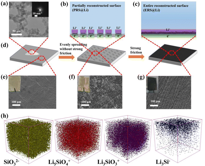
As shown in Fig. 1(a), the particle size of fumed silica is approximately 20 nm. The inset in Fig. 1(a) shows that fumed silica is amorphous. The dangling bonds and distorted SiO4 tetrahedra in amorphous SiO2 can react with lithium and the lithiation process of amorphous SiO2 is thermodynamically feasible.23,24Fig. 1(b)–(d) show the model and process of mechanochemical reconstruction of the Li foil surface. With varying degrees of mechanical friction, fumed silica nanoparticles exhibit different states on the surface of the Li foil.When the fumed silica nanoparticles were lightly wiped onto the surface of Li foil without repeated strong friction (Fig. 1(d)), due to the strong interaction force of fumed nano-silica, the clustered fumed silica nanoparticles adhered to partial areas on the surface of the Li foil (Fig. 1(d) and (f)). At this stage, the surface of the Li foil was partially reconstructed by fumed silica nanoparticles (Fig. 1(b), (d) and (f)). Then, repeated strong rubbing of the surface of PRS@Li caused the agglomerated fumed silica nanoparticles to disperse evenly over the Li foil surface and the surface of the Li foil was entirely reconstructed by fumed silica nanoparticles (Fig. 1(c), (d) and (g)). X-ray photoelectron spectroscopy (XPS) was used to detect the changes in chemical composition on the surface of the Li foil during the mechanochemical reconstruction process (Fig. S1 and Fig. S2, ESI†). The Li 1s spectrum of the bare Li foil surface, shown in Fig. S1, ESI,† is consistent with the literature,4,5,13 and the primitive passivation layer of bare Li foil was composed of Li2CO3, Li2O and LiOH, which were detected at 56.0 eV, 54.0 eV and 55.3 eV in the Li 1s branch, respectively. Compared with fumed silica powder, the Si 2p peaks of PRS@Li and ERS@Li all show a chemical shift towards the direction of low binding energy, and a new peak appears near 99.0 eV, which indicates that the fumed silica nanoparticles were lithiated to form LixSiOy and LixSi.11 The offset of ERS@Li is larger than that of PRS@Li, which indicates that under the strong repeated mechanical friction force, fumed silica nanoparticles were more fully lithiated and the surface was evenly covered with black reactants (Fig. 1(e)–(g)). Time of flight secondary ion mass spectrometry (TOF-SIMS) was applied to further clarify the reaction products (Fig. 1(h) and Fig. S3 and S4, ESI†) and the results of depth sputtering show that the lithiated fumed silica is a mixture of unreacted silica, Li2SiO3, Li4SiO4 and LixSi. The mechanochemical reaction mechanism of fumed silica with Li is expected to follow the reaction equations:
| 2SiO2 + 4Li → Li4SiO4 + Si | (1) |
| 3SiO2 + 4Li → 2Li2SiO3 + Si | (2) |
| Si + xLi → LixSi | (3) |
Under the strong mechanical friction force, the surface of Li foil was entirely reconstructed into a porous modified layer with a thickness of about 17.6 μm (Fig. S5, ESI†), which was composed of a mixture of lithiated fumed silica and lithium (Fig. 1(h) and Fig. S4, ESI†). Li4SiO4 and Li2SiO3 are considered to be materials with high conductivity for Li+.23 And LixSi can serve as an excellent lithiophilic nucleation site.16 Therefore, lithiated fumed silica nanoparticles can become excellent active sites for Li deposition and stripping (Fig. 1(b) and (c)).
2.2 The action mechanism of the reconstructed surface at the Li anode interface
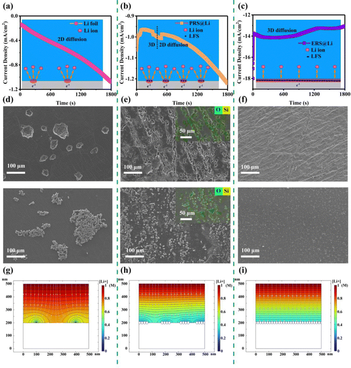
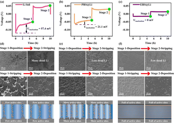
In order to explore the effect of Li foil surface reconstruction on the behavior of Li deposition and stripping, a chronoamperometry (CA) test was conducted on symmetric cells (Fig. 2(a)–(c)). Driven by a constant voltage, the electrochemical reaction begins at the active sites at the interface of the lithium electrodes, resulting in a current density–time curve. According to the Butler–Volmer equation, the current density–time curve can reflect the morphological changes in the electrochemical interface during deposition and stripping of Li.11 This means that during constant voltage, interfacial instability (inhomogeneous stripping and growth of lithium dendrites) of the lithium anodes leads to a continuous increase in the area of electrochemical reaction, causing the current density to continuously increase. Conversely, the current density stabilizes and decreases. As shown by the results of the CA test (Fig. 2(a)–(c)), the Li foil electrode exhibits a linearly increasing curve over the whole test process, reflecting an unstable interface morphology over the whole test process. And the PRS@Li electrode exhibits a linearly increasing curve after being stable at about 0.83 mA cm−2 for 540 s, demonstrating that the electrochemical interface morphology stabilizes in the early stage but fails at the later stage. The phenomena found in the Li foil electrode and PRS@Li electrode are due to the uneven distribution of active sites at the electrochemical interface (Fig. 2(a) and (b)). By contrast, the current density of the ERS@Li electrode was almost unchanged and stable at about 13 mA cm−2 throughout the CA test process, reflecting that there are enough uniform active sites at the interface of ERS@Li to achieve a stable interface morphology during the deposition and stripping of Li (Fig. 2(c)). Moreover, in the CA test, the current density of the ERS@Li electrode was the highest, followed by that of the PRS@Li electrode, while that of the Li foil electrode was the lowest, consistent with the changing role of the active sites on the surface of these electrodes. SEM images of the surface morphology of ERS@Li, PRS@Li and Li foil after the CA test are shown in Fig. 2(d)–(f), where the electrode surface morphologies of these electrodes are consistent with the above CA test results. Interestingly, as shown in Fig. 2(e), the deposition and stripping reactions of Li only occur in areas with surface reconstruction, which proves the model proposed in Fig. 1(b) and (c). Moreover, we conducted a finite element simulation of the electrochemical reaction process of these three electrodes based on the proportion of surface active area (Fig. 2(g)–(i) and Fig. S6 and S7, ESI†). The simulation results indicate that surface reconstruction increases the active area of the surface, making the electrochemical reaction at the interface more uniform, reducing the local current and electric field distribution (Fig. S8 and S9, ESI†), homogenizing the Li+ flow (Fig. 2(g)–(i)), and thus inhibiting the growth of Li dendrites.Fig. 3 shows that as the surface reconstruction area increases, the polarization voltage and nucleation overpotential decrease accordingly, which is consistent with the conclusion obtained from the finite element simulation in Fig. S8 and S9, ESI.† Significantly, when the surface is entirely reconstructed (ERS@Li), its nucleation overpotential is almost zero. During the process of stripping Li, the Li dendrites fracture from the root to produce dead Li, resulting in a decrease in the amount of active Li deposited. Therefore, in the later stage of charging, it is necessary to strip the fresh surface again, which causes a sudden increase in polarization and a peak at the end of the voltage curve (Fig. 3(a) and (b)).25 When the surface is completely reconstructed, the voltage profile presents a square wave shape, indicating that there is no generation of Li dendrites or dead Li during the lithium deposition and stripping process. The surface morphology of the electrodes at each stage (Fig. 3(d)–(f)) further confirms the above analysis and the corresponding schemes are shown in Fig. 3(g)–(i). It is worth noting that the deposition morphology on the ERS@Li electrode is completely dense, and even the presence of Li blocks cannot be observed. Therefore, after reconstructing the surface of Li foil with fumed silica nanoparticles, the polarization voltage and nucleation overvoltage can be greatly reduced, and uniform stripping and dendrite-free Li deposition are achieved, thereby inhibiting the generation of dead Li and reducing the consumption of electrolyte.
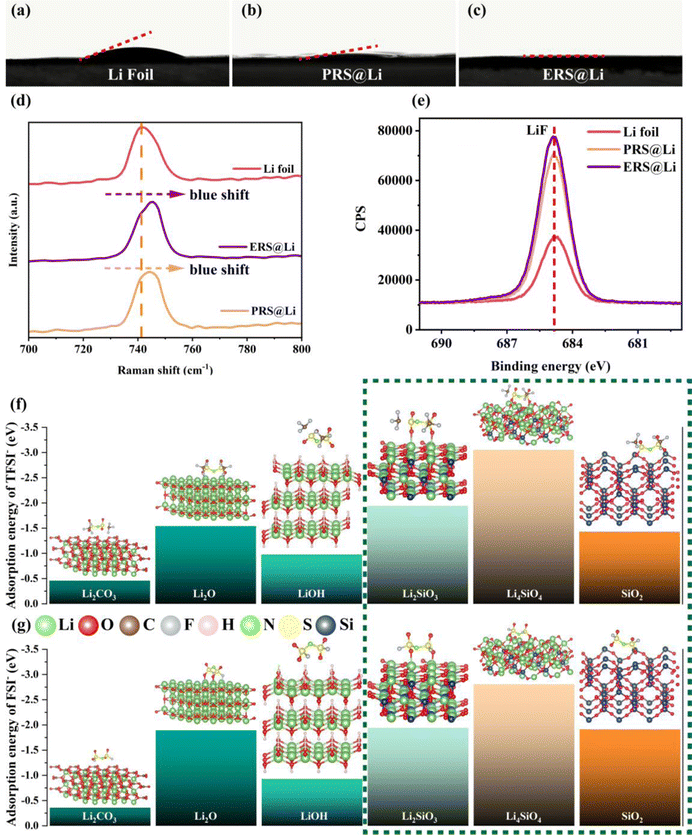
After surface reconstruction, the wettability between the surface and the electrolyte is greatly improved (Fig. 4(a)–(c)). This shows that compared with the primitive surface of Li foil, the reconstructed surface has different interactions with the electrolyte: for instance, the polar groups of the fumed silica can promote wettability with a polar electrolyte.26 In order to further explore the interaction between the reconstructed surface and the electrolyte, Raman testing was conducted at the interface between the electrolyte and the surface of Li (Fig. 4(d)). The Raman peak of S–N stretching in TFSI− near the surface of the Li foil at 741.7 cm−1 is blue shifted to 745.6 cm−1 near the surface of ERS@Li and to 744.6 cm−1 near the surface of PRS@Li, which indicates that TFSI− can be adsorbed on the reconstructed surface, which is consistent with the conclusions in the literature, that TFSI− can spontaneously adsorb on the surface of silica.21 The “anionphilic” reconstructed surface can reduce the “space charge” distribution, thereby inhibiting the growth of Li dendrites.27 On the other hand, the more anions that exist at the electrochemical interface, the more anions are decomposed during the formation of SEI, thus achieving an LiF-rich SEI.28 As shown in Fig. 4(e), after plating Li, the peak intensity of LiF in the SEI of the PRS@Li electrode and the ERS@Li electrode are significantly higher than that of the Li foil electrode.29 Hence, combining the results of XPS characterization on the surface after Li deposition (Fig. 4(e)), we can confirm that the reconstructed surface can promote the decomposition of TFSI− and form an SEI rich in LiF. In order to further investigate the adsorption of anions on the reconstructed surface, we calculated the adsorption of anions (TFSI− and FSI−) on the materials on the primitive surface of Li foil (Li2O, LiOH and Li2CO3) and the materials on the reconstructed surface (Li2SiO3, Li4SiO4 and SiO2). We found that compared with the materials on the primitive surface, the silicon-containing materials formed on the reconstructed surface show stronger adsorption of anions; in particular, the adsorption energy of Li4SiO4 with anions reached the level of −3 eV (Fig. 4(f) and (g)).
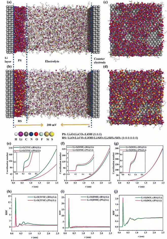
Moreover, molecular dynamics (MD) simulations of the Li plating process at the electrochemical interface of the primitive surface of Li foil (PS@Li) and reconstructed surface of Li foil (RS) were carried out to further explain the positive effect of the reconstructed surface on the Li plating behavior. As shown in Fig. 5(a) and (b), we have constructed a model that is closer to the actual Li plating process. Fig. 5(c)–(d) reflect the distribution of molecules and Li ions near the surface of the two Li electrodes. Compared with the primitive surface of Li foil, the reconstructed surface can increase and homogenize the distribution of Li ions at the interface. In the same area, the number of Li ions near the primitive surface of Li foil is 427, and that near the reconstructed surface is 517 (Fig. 5(c)–(d) and Fig. S10, ESI†). In order to further verify the mechanisms of the different solvation structures of Li ions at the interface of the two Li anodes found in Fig. 4, the radial distribution functions and coordination numbers were calculated. As shown in Fig. 5(e)–(j), RS@Li results in more anions and fewer solvent molecules at the interface during Li plating. This is consistent with the conclusion drawn in Fig. 4, further proving that the materials (Li2SiO3, Li4SiO4 and SiO2) formed on the reconstructed surface can exhibit an anionic property, which can greatly enhance the stability of the electrochemical interface.
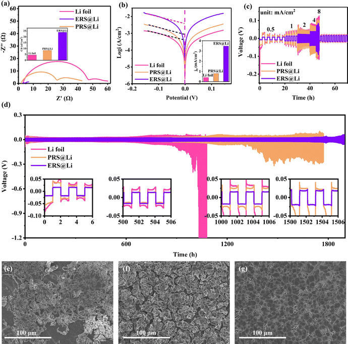
Li‖Li symmetrical cells were prepared to evaluate the electrochemical performance of the surface-reconstructed Li foil anode. From Fig. 6(a), we can conclude that the reconstructed surface can greatly reduce the interfacial impedance and improve the interfacial capacitance, which then effectively eliminates electrochemical polarization.11 This is why the nucleation overpotential of ERS@Li is close to zero (Fig. 3(c)). The exchange current densities of Li foil, PRS@Li and ERS@Li are 0.42 mA cm−2, 0.81 mA cm−2 and 3.48 mA cm−2, respectively (Fig. 6(b)), which demonstrates that the reconstructed surface at the interface enhances the electrode reaction kinetics. As a result, the ERS@Li anode exhibited superior rate capability to both the PRS@Li anode and the Li foil foil anode (Fig. 6(c)). As shown in Fig. 6(d), the symmetrical cells were cycled at a fixed capacity of 1 mA h cm−2 under a current density of 1 mA cm−2. The Li foil anode exhibited a larger overpotential which increased to over 100 mV after 900 h due to the severe consumption of electrolyte and accumulation of dead Li at the interface, while an enhanced electrochemical performance could be observed for the PRS@Li anode, which exhibited a stable cyclic polarization voltage with a prolonged lifespan of >1000 h, due to the addition of a reconstructed surface that made the electrochemical reaction at the interface more uniform. In strong contrast, the ERS@Li anode exhibited stable voltage polarization with an ultra-low overpotential of about 18 mV even after 1500 h. Additionally, the surface morphology of the Li foil electrode after cycling was filled with dendrites and dead Li, and there existed areas that had not been utilized yet (Fig. 6e), due to the lack of electrochemically active sites. The surface morphology of the PRS@Li electrode after cycling was porous and loose sedimentary Li particles mixed with dead Li covered the entire surface (Fig. 6(f)). A significant difference is shown in the surface morphology after cycling of the ERS@Li electrode: a flat and smooth morphology without dead Li or Li dendrites (Fig. 6(g)). Therefore, the superior cycling stability, ultra-low cyclic polarization voltage, superior rate performance and dendrite-free morphology after cycling of the ERS@Li‖ERS@Li symmetrical cell further prove the beneficial mechanism of the reconstructed surface on the interface electrochemical performance proposed above.
2.3 Practical Li metal pouch cells based on an entirely reconstructed surface of Li foil
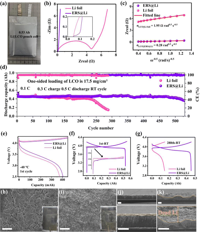
Li‖LCO pouch cells have important applications in 3C electronic products.30 We applied a commercial double-sided coated LCO electrode with a single-side loading of 17 mg cm−2 of LCO, matched with 120 μm-thick Li foil or surface-reconstructed Li foil as anode for assembly into 0.53 A h pouch cells (Fig. 7(a)). A realistic electrolyte injection coefficient of 3 g A−1 h−1 was used to meet the demand for Li metal batteries with high specific energy. As shown in Fig. 7(b), due to the ERS layer possessing excellent wettability with the electrolyte, high Li+ conductivity and Li affinity, the use of ERS@Li as the anode greatly reduces the interfacial impedance of the Li‖LCO pouch cell (∼142 times). Additionally, information on Li+ diffusion can be obtained by analyzing the inclined line in the low-frequency region, which is the so-called Warburg diffusion. The Warburg coefficient (σ) can be obtained from eqn (4):31| Zre = Ro + Rct + σω−0.5 | (4) |
 | (5) |
![[thin space (1/6-em)]](https://www.rsc.org/images/entities/char_2009.gif) 485 C mol−1) and C is the molar concentration of Li+. It was found that the DLi of the ERS@Li‖LCO pouch cell is 2.03 × 10⁻¹² cm2 s−1, which is almost two orders of magnitude larger than that of the Li foil‖LCO pouch cell (4.19 × 10⁻¹⁴ cm2 s−1). Due to having the same battery configuration, the enhancement of the diffusion coefficient of ERS@Li‖LCO is mainly attributed to the ERS@Li anode. Fig. 7(d) shows that the ERS@Li‖LCO pouch cell exhibits a markedly higher capacity retention of 93% after 500 cycles at 0.3 C charge and 0.5 C discharge rates compared with Li foil‖LCO, which is a superior cycling performance compared to other relevant reports (Table S1, ESI†). Moreover, employing ERS@Li as the anode can improve the charging and discharging capacity of Li‖LCO pouch cells at −40 °C (Fig. 7(e) and Fig. S11, ESI†) and reduce the charging and discharging polarization (Fig. 7(f)), which are evidence that ERS can greatly reduce battery impedance (Fig. 7(b)) and enhance the migration of Li+. At the 288th cycle, the Li foil‖LCO pouch cell had basically failed, while the capacity of ERS@Li‖LCO had hardly decayed (Fig. 7(g)). Moreover, the cycled Li‖LCO pouch cells (discharge state) at the 288th cycle were disassembled to analyze the mechanism of performance difference between the ERS@Li anode and the Li foil anode. The cycled Li foil anode is very sticky to the separator and a lot of powdery Li sticks to the separator, while the cycled ERS@Li anode is almost non-sticky to the separator and very little powdery Li adheres to the separator (Fig. S13, ESI†). It is worth noting that significantly reducing the adhesion of powdery Li to the separator is of great significance for practical Li–metal batteries, as the powdery Li adhered to the separator can cause both a decrease in battery capacity and serious safety issues due to internal short circuiting. The surface morphology of the cycled ERS@Li is a bulk morphology of the Li removal state (Fig. 7(h) and Fig. S14, ESI†), while that of the cycled Li foil anode is composed of tiny flocculent dead Li (Fig. 7(i) and Fig. S15, ESI†). Correspondingly, the thickness of the powdery layer of the cycled ERS@Li is much thinner than that of the cycled Li foil anode (Fig. 7(j) and (k)). The thickness of dead Li of the cycled Li foil anode is about 143 μm, while that of the cycled ERS@Li anode is only 15 μm.
485 C mol−1) and C is the molar concentration of Li+. It was found that the DLi of the ERS@Li‖LCO pouch cell is 2.03 × 10⁻¹² cm2 s−1, which is almost two orders of magnitude larger than that of the Li foil‖LCO pouch cell (4.19 × 10⁻¹⁴ cm2 s−1). Due to having the same battery configuration, the enhancement of the diffusion coefficient of ERS@Li‖LCO is mainly attributed to the ERS@Li anode. Fig. 7(d) shows that the ERS@Li‖LCO pouch cell exhibits a markedly higher capacity retention of 93% after 500 cycles at 0.3 C charge and 0.5 C discharge rates compared with Li foil‖LCO, which is a superior cycling performance compared to other relevant reports (Table S1, ESI†). Moreover, employing ERS@Li as the anode can improve the charging and discharging capacity of Li‖LCO pouch cells at −40 °C (Fig. 7(e) and Fig. S11, ESI†) and reduce the charging and discharging polarization (Fig. 7(f)), which are evidence that ERS can greatly reduce battery impedance (Fig. 7(b)) and enhance the migration of Li+. At the 288th cycle, the Li foil‖LCO pouch cell had basically failed, while the capacity of ERS@Li‖LCO had hardly decayed (Fig. 7(g)). Moreover, the cycled Li‖LCO pouch cells (discharge state) at the 288th cycle were disassembled to analyze the mechanism of performance difference between the ERS@Li anode and the Li foil anode. The cycled Li foil anode is very sticky to the separator and a lot of powdery Li sticks to the separator, while the cycled ERS@Li anode is almost non-sticky to the separator and very little powdery Li adheres to the separator (Fig. S13, ESI†). It is worth noting that significantly reducing the adhesion of powdery Li to the separator is of great significance for practical Li–metal batteries, as the powdery Li adhered to the separator can cause both a decrease in battery capacity and serious safety issues due to internal short circuiting. The surface morphology of the cycled ERS@Li is a bulk morphology of the Li removal state (Fig. 7(h) and Fig. S14, ESI†), while that of the cycled Li foil anode is composed of tiny flocculent dead Li (Fig. 7(i) and Fig. S15, ESI†). Correspondingly, the thickness of the powdery layer of the cycled ERS@Li is much thinner than that of the cycled Li foil anode (Fig. 7(j) and (k)). The thickness of dead Li of the cycled Li foil anode is about 143 μm, while that of the cycled ERS@Li anode is only 15 μm.
LFP batteries are promising power batteries for new energy vehicles due to their superior cycling performance, safety performance and low cost.33 However, their poor low-temperature performance limits their application in cold regions. An interface with high Li+ transport is crucial for low-temperature batteries.34 Fig. S16, ESI,† shows that using ERS@Li as the anode can significantly reduce the impedance and enhance Li+ transport, resulting in improved electrochemical performance for LFP batteries at −20 °C (Fig. S17a, ESI†). Observing the surface of the Li anodes after cycling, it was found that the surface of the ERS@Li anode had a blocky Li deposition morphology, while there were many Li dendrites on the surface of the Li foil anode (Fig. S17b, ESI†). Therefore, the ERS@Li anode can enhance the migration of Li+ and suppress the growth of Li dendrites at −20 °C, thereby assisting in the application of LFP batteries in a low-temperature environment.
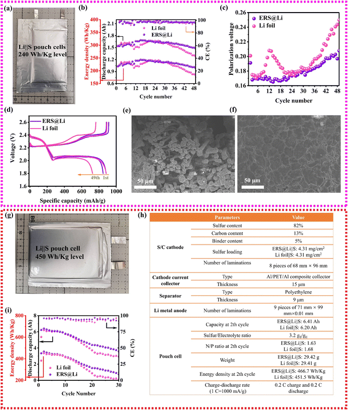
Li‖S batteries are a promising as high-specific-energy and low-cost Li metal batteries and show important application prospects in the field of unmanned aerial vehicles.35 To investigate the performance of an ERS@Li anode in practical Li‖S pouch cells, as shown in Fig. 8(a), 1.6 A h Li‖S pouch cells with about 240 W h kg−1 were prepared and the manufacturing parameters are shown in Table S2 (ESI†). As shown in Fig. 8(b)–(d), using an ERS@Li anode can achieve high capacity retention of 96% until the 49th cycle and reduce the charge and discharge polarization of the Li‖S pouch cell, which is consistent with the above analysis. The dendrite-free morphology of the cycled ERS@Li anode further proves that ERS@Li‖S has superior electrochemical performance (Fig. 8(e) and (f)). Moreover, applying an ERS@Li anode can also improve the electrochemical performance of an Li‖S pouch cell with a higher energy density of more than 450 W h kg−1 (Fig. 8(g) and (h)) at a high rate of 0.2 C charge–discharge (Fig. 8(i) and Fig. S18 and19, ESI†).
ERS has the ability to induce the tight deposition of Li into a smooth plane, which greatly reduces the powdering of Li in practical pouch cells, improves the cycling performance and safety performance of practical Li metal batteries, and is of great significance for the commercialization of Li metal batteries (Fig. 9(a)). Therefore, using this simple and low-cost surface reconstruction strategy can effectively improve the performance of practical lithium metal pouch cells (0.53 A h Li‖LCO pouch cell, 1.6 A h Li‖S pouch cell with 240 W h kg−1 level and high-energy-density Li‖S pouch cell with 450 W h kg−1 level), and the performance has reached industry-leading levels (Fig. 9(b) and (c)).
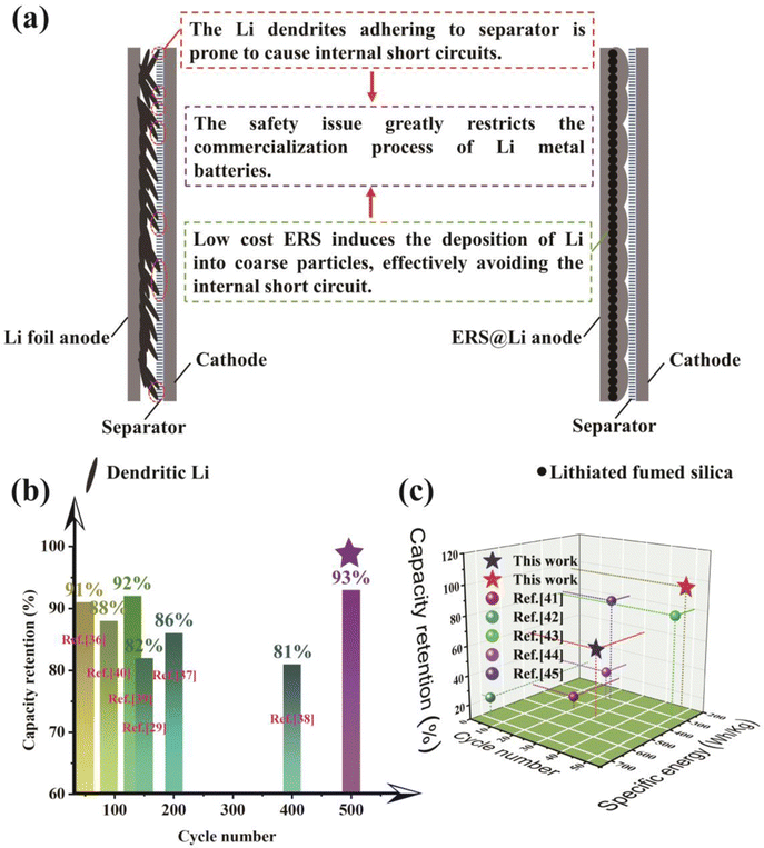 | ||
| Fig. 9 (a) Significance of ERS@Li for commercialization of lithium metal batteries. The state-of-the-art performance of (b) Li‖LCO pouch cells29,36–40 and (c) Li‖S pouch cells in published literature and this work.41–45 | ||
3 Conclusions
A low-cost and effective mechanochemical surface-reconstruction strategy for Li foil was proposed to solve the key problem for a commercial Li foil anode, that is the uneven surface primitive passivation film resulting in poor electrochemical performance. The reconstructed surface is rich in nanoscale dispersed silica, Li2SiO3, Li4SiO4, and LixSi. After detailed experiments, DFT calculations and molecular dynamics simulations, we found that the entire reconstructed surface of Li foil (ERS@Li) can not only induce uniform deposition and stripping of Li and enhance electrode dynamics, but can also construct an anionphilic interface. Significantly, we evaluated the application of Li foil with an entire reconstructed surface (ERS@Li) in practical high-specific-energy Li metal pouch cells in different application scenarios. As a result, the ERS@Li anode demonstrates superior performance in 0.53 A h Li‖LCO pouch cells, low-temperature Li‖LFP cells, 1.6 A h Li‖S pouch cells and 6.4 A h Li‖S pouch cells with 466.7 W h kg−1. An excellent cycling performance with 93% capacity retention after 500 cycles at 0.3 C charge and 0.5 C discharge was achieved by a 0.53 A h ERS@Li‖LCO pouch cell. Our findings provide a path for the commercialization of Li metal batteries.Conflicts of interest
The authors declare no interest conflict. They have no known competing financial interests or personal relationships that could have appeared to influence the work reported in this paper.Acknowledgements
The work was financially supported by the National Natural Science Foundation of China (U1904216, U22A20141), the National Natural Science Foundation of China (No. 52377222) and Natural Science Foundation of Hunan Province (No. 2023JJ20064). The authors would like to thank KW-ST Lab (https://www.kewei-scitech.com/) and Shiyanjia Lab (https://www.shiyanjia.com/) for the SEM and XPS analysis.References
- M. S. Kim, Z. Zhang, J. Wang, S. T. Oyakhire, S. C. Kim, Z. Yu, Y. Chen, D. T. Boyle, Y. Ye, Z. Huang, W. Zhang, R. Xu, P. Sayavong, S. F. Bent, J. Qin, Z. Bao and Y. Cui, ACS Nano, 2023, 17, 3168–3180 CrossRef CAS.
- Y. Feng, B. Zhong, R. Zhang, M. Peng, Z. Hu, Z. Wu, N. Deng, W. Zhang and K. Zhang, Adv. Energy Mater., 2023, 13, 2203912 CrossRef CAS.
- M. Baek, J. Kim, K. Jeong, S. Yang, H. Kim, J. Lee, M. Kim, K. J. Kim and J. W. Choi, Nat. Commun., 2023, 14, 1296 CrossRef CAS.
- D. Aurbach, J. Power Sources, 2000, 89, 206–218 CrossRef CAS.
- O. B. Chae and B. L. Lucht, Adv. Energy Mater., 2023, 13 DOI:10.1002/aenm.202203791.
- T. Fujieda, N. Yamamoto, K. Saito, T. Ishibashi, M. Honjo, S. Koike, N. Wakabayashi and S. Higuchi, J. Power Sources, 1994, 52, 197–200 CrossRef CAS.
- K. Kanamura, H. Takezawa, S. Shiraishi and Z. I. Takehara, J. Electrochem. Soc., 1997, 144, 1900–1906 CrossRef CAS.
- W. Tang, X. Yin, Z. Chen, W. Fu, K. P. Loh and G. W. Zheng, Energy Storage Mater., 2018, 14, 289–296 CrossRef.
- X. Gao, Y.-N. Zhou, D. Han, J. Zhou, D. Zhou, W. Tang and J. B. Goodenough, Joule, 2020, 4, 1864–1879 CrossRef CAS.
- Z. Han, H. R. Ren, Z. Huang, Y. Zhang, S. Gu, C. Zhang, W. Liu, J. Yang, G. Zhou, Q. H. Yang and W. Lv, ACS Nano, 2023, 17, 4453–4462 CrossRef CAS PubMed.
- K. Long, S. Huang, H. Wang, Z. Jin, A. Wang, Z. Wang, P. Qing, Z. Liu, L. Chen, L. Mei and W. Wang, Energy Storage Mater., 2023, 58, 142–154 CrossRef.
- K. Zhao, L. Zhang, Q. Jin, J. Xiao, L. Wu and X. Zhang, ACS Appl. Mater. Interfaces, 2023, 15, 3089–3098 CrossRef CAS PubMed.
- A. Hu, W. Chen, X. Du, Y. Hu, T. Lei, H. Wang, L. Xue, Y. Li, H. Sun, Y. Yan, J. Long, C. Shu, J. Zhu, B. Li, X. Wang and J. Xiong, Energy Environ. Sci., 2021, 14, 4115–4124 RSC.
- Z. Peng, J. Song, L. Huai, H. Jia, B. Xiao, L. Zou, G. Zhu, A. Martinez, S. Roy, V. Murugesan, H. Lee, X. Ren, Q. Li, B. Liu, X. Li, D. Wang, W. Xu and J. G. Zhang, Adv. Energy Mater., 2019, 9, 1901764 CrossRef CAS.
- J. Y. Kim, A. Y. Kim, G. Liu, J.-Y. Woo, H. Kim and J. K. Lee, ACS Appl. Mater. Interfaces, 2018, 10, 8692–8701 CrossRef CAS PubMed.
- W. Tang, X. Yin, S. Kang, Z. Chen, B. Tian, S. L. Teo, X. Wang, X. Chi, K. P. Loh, H. W. Lee and G. W. Zheng, Adv. Mater., 2018, 30, e1801745 CrossRef.
- M. Jiang, Q. Zhang, D. L. Danilov, R.-A. Eichel and P. H. L. Notten, ACS Appl. Energy Mater., 2021, 4, 10333–10343 CrossRef CAS.
- B. Acebedo, M. C. Morant-Miñana, E. Gonzalo, I. Ruiz de Larramendi, A. Villaverde, J. Rikarte and L. Fallarino, Adv. Energy Mater., 2023, 13 DOI:10.1002/aenm.202203744.
- M.-H. Ryou, Y. M. Lee, Y. Lee, M. Winter and P. Bieker, Adv. Funct. Mater., 2015, 25, 834–841 CrossRef CAS.
- W. Chen, R. V. Salvatierra, J. T. Li, D. X. Luong, J. L. Beckham, V. D. Li, N. La, J. Xu and J. M. Tour, Adv. Mater., 2022, 34, e2202668 CrossRef.
- Y. Liao, L. Yuan, X. Liu, J. Meng, W. Zhang, Z. Li and Y. Huang, Energy Storage Mater., 2022, 48, 366–374 CrossRef.
- Y. Yuan, F. Wu, Y. Liu, X. Wang, K. Zhang, L. Zheng, Z. Wang, Y. Bai and C. Wu, ACS Appl. Mater. Interfaces, 2020, 12, 39362–39371 CrossRef CAS.
- Y.-S. Su, K.-C. Hsiao, P. Sireesha and J.-Y. Huang, Batteries, 2022, 8, 2 CrossRef CAS.
- E. Sivonxay, M. Aykol and K. A. Persson, Electrochim. Acta, 2020, 331, 135344 CrossRef CAS.
- D. Kang, N. Hart, M. Xiao and J. P. Lemmon, Acta Phys. Chim. Sin., 2020, 2008013 Search PubMed.
- R. Pathak, K. Chen, A. Gurung, K. M. Reza, B. Bahrami, F. Wu, A. Chaudhary, N. Ghimire, B. Zhou, W. H. Zhang, Y. Zhou and Q. Qiao, Adv. Energy Mater., 2019, 9, 1901486 CrossRef.
- W. Zhang, H. L. Zhuang, L. Fan, L. Gao and Y. Lu, Sci. Adv., 2018, 4, eaar4410 CrossRef PubMed.
- Y. Zhao, T. Zhou, M. Mensi, J. W. Choi and A. Coskun, Nat. Commun., 2023, 14 DOI:10.1038/s41467-023-35934-1.
- H. Su, Z. Chen, M. Li, P. Bai, Y. Li, X. Ji, Z. Liu, J. Sun, J. Ding, M. Yang, X. Yao, C. Mao and Y. Xu, Adv. Mater., 2023, e2301171, DOI:10.1002/adma.202301171.
- J. Liu, B. Yuan, N. He, L. Dong, D. Chen, S. Zhong, Y. Ji, J. Han, C. Yang, Y. Liu and W. He, Energy Environ. Sci., 2023, 16, 1024–1034 RSC.
- H. Liu, C. Li, H. P. Zhang, L. J. Fu, Y. P. Wu and H. Q. Wu, J. Power Sources, 2006, 159, 717–720 CrossRef CAS.
- X. Du, W. He, X. Zhang, Y. Yue, H. Liu, X. Zhang, D. Min, X. Ge and Y. Du, J. Mater. Chem., 2012, 22, 5960 RSC.
- H. Zhang, D. Ren, H. Ming, W. Zhang, G. Cao, J. Liu, L. Wang, J. Song, J. Qiu, J. Wang, X. He and H. Zhang, Adv. Energy Mater., 2022, 13, 2202660 CrossRef.
- J. Huang, X. Dong, N. Wang and Y. Wang, Curr. Opin. Electrochem., 2022, 33, 100949 CrossRef CAS.
- Z. X. Chen, M. Zhao, L. P. Hou, X. Q. Zhang, B. Q. Li and J. Q. Huang, Adv. Mater., 2022, 34, e2201555 CrossRef PubMed.
- K. Huang, S. Bi, B. Kurt, C. Xu, L. Wu, Z. Li, G. Feng and X. Zhang, Angew. Chem., Int. Ed., 2021, 60, 19232–19240 CrossRef CAS PubMed.
- C. Niu, H. Lee, S. Chen, Q. Li, J. Du, W. Xu, J.-G. Zhang, M. S. Whittingham, J. Xiao and J. Liu, Nat. Energy, 2019, 4, 551–559 CrossRef CAS.
- C. Niu, D. Liu, J. A. Lochala, C. S. Anderson, X. Cao, M. E. Gross, W. Xu, J.-G. Zhang, M. S. Whittingham, J. Xiao and J. Liu, Nat. Energy, 2021, 6, 723–732 CrossRef CAS.
- Q.-K. Zhang, X.-Q. Zhang, J. Wan, N. Yao, T.-L. Song, J. Xie, L.-P. Hou, M.-Y. Zhou, X. Chen, B.-Q. Li, R. Wen, H.-J. Peng, Q. Zhang and J.-Q. Huang, Nat. Energy, 2023, 8, 725–735 CrossRef CAS.
- C. Z. Zhao, P. Y. Chen, R. Zhang, X. Chen, B. Q. Li, X. Q. Zhang, X. B. Cheng and Q. Zhang, Sci. Adv., 2018, 4, eaat3446 CrossRef CAS.
- Z.-X. Chen, L.-P. Hou, C.-X. Bi, Q. Cheng, X.-Q. Zhang, B.-Q. Li and J.-Q. Huang, Energy Storage Mater., 2022, 53, 315–321 CrossRef.
- Q. Cheng, Z.-X. Chen, X.-Y. Li, L.-P. Hou, C.-X. Bi, X.-Q. Zhang, J.-Q. Huang and B.-Q. Li, J. Energy Chem., 2023, 76, 181–186 CrossRef CAS.
- Y. Guo, Z. Jin, J. Lu, Z. Wang, Z. Song, A. Wang, W. Wang and Y. Huang, Energy Environ. Mater., 2022, e12479 Search PubMed.
- L. Shi, S.-M. Bak, Z. Shadike, C. Wang, C. Niu, P. Northrup, H. Lee, A. Y. Baranovskiy, C. S. Anderson, J. Qin, S. Feng, X. Ren, D. Liu, X.-Q. Yang, F. Gao, D. Lu, J. Xiao and J. Liu, Energy Environ. Sci., 2020, 13, 3620–3632 RSC.
- X. Q. Zhang, Q. Jin, Y. L. Nan, L. P. Hou, B. Q. Li, X. Chen, Z. H. Jin, X. T. Zhang, J. Q. Huang and Q. Zhang, Angew. Chem., Int. Ed., 2021, 60, 15503–15509 CrossRef CAS PubMed.
Footnote |
| † Electronic supplementary information (ESI) available. See DOI: https://doi.org/10.1039/d3ee03185c |
| This journal is © The Royal Society of Chemistry 2024 |

