
 Open Access Article
 This Open Access Article is licensed under a
 Creative Commons Attribution 3.0 Unported Licence
Centrosymmetric to non-centrosymmetric transition in the Ca2−xMnxTi2O6 double perovskite system studied through structural analysis and dielectric properties†
Elisabeth K.
Albrecht
a,
Tuomo
Siponkoski
 b,
Eeva-Leena
Rautama
a,
Maarit
Karppinen
a and
Antti J.
Karttunen
*a
b,
Eeva-Leena
Rautama
a,
Maarit
Karppinen
a and
Antti J.
Karttunen
*a
aDepartment of Chemistry and Materials Science, Aalto University, P.O. Box 16100, FI-00076 Aalto, Finland. E-mail: antti.karttunen@aalto.fi
bMicroelectronics Research Unit, University of Oulu, P.O. Box 4500, FI-90014 Oulu, Finland
First published on 11th March 2024
Abstract
We have used high-pressure synthesis to synthesize samples of Ca2−xMnxTi2O6 double perovskite, where x varies between 0.2 and 1. The synthesized materials were structurally characterized with powder X-ray diffraction (XRD). Rietveld refinement of the XRD patterns was used to study the change from CaTiO3 (x = 0) to the composition CaMnTi2O6 (x = 1) where half of the Ca(II) ions are replaced by smaller Mn(II) ions. We analyzed the peak shapes in the XRD patterns, as well as lattice parameters, and it appears that smooth symmetry change from the centrosymmetric space group Pbnm to the non-centrosymmetric space group P42mc occurs between x = 0.3 and x = 0.5. We also confirmed the centrosymmetric to non-centrosymmetric transition by characterizing the dielectric properties of the materials with ferroelectric measurements.
1. Introduction
Ferroelectric materials show spontaneous polarization which is switchable by a sufficiently high electric field. When the polarization of a material is measured with respect to the applied electric field, ferroelectric materials show a hysteresis behaviour where the polarization does not reach zero when the electric field is switched off. The remaining polarization and the electric field needed to bring the polarization down to zero characterize the ferroelectric material. Especially for energy storage purposes, ferroelectrics are a promising option.1,2 The storage of energy provided by renewable sources to guarantee on-demand energy supply is a pressing issue and ferroelectric materials could be used in the transformation towards a more sustainable energy infrastructure. Additionally, owing to their symmetry properties, ferroelectrics show by definition also pyroelectricity and piezoelectricity. Such materials have a whole set of interesting properties which can be tuned and optimized for different purposes such as sensors and energy harvesting.3,4Perovskites are a wide class of compounds that are known for their various functionalities such as piezoelectricity, ferroelectricity, multiferroicity, superconductivity, and pyroelectricity.5 The ideal perovskite structure has the composition ABX3 with a cubic unit cell in the space group Pm3m. The X-anions form an octahedron around the B-cation, which sits in the center of the cube. The A-cation occupies the corners. While an ideal perovskite does not have a polarspace group and thus cannot exhibit pyroelectricity, at room temperature perovskites often are distorted, the X-octahedra can be tilted and cations displaced.6,7 The variety of properties is further increased when considering double perovskites, also called complex perovskites. In double perovskites, either the A-site or the B-site is occupied by two different elements, A-site (ordered) double perovskites (AA′B2X6) and B-site (ordered) double perovskites (A2BB′X6), respectively. While there has been a lot of research on B-site ordered double perovskites, A-site ordered double perovskites are much less researched. The cations can order in three different ways, columnar, planar or in a rock salt pattern.8 The cations can also be disordered and form a solid solution.9
Unfortunately, the most common and efficient ferroelectric and thus pyroelectric (double) perovskites contain lead or bismuth which are toxic and harmful. The most well-known is Pb(Zr,Ti)O3.10 Lately, attention has been drawn to lead-free alternatives like BaTiO3.11–13 As for double perovskites, Aimi et al. used in 2014 high-pressure methods to synthesize a non-harmful A-site ordered double perovskite CaMnTi2O6 with a columnar cation ordering (see Fig. 1). Due to tilting of the oxygen octahedra, the A-site cation coordination deviates from the 12-fold coordination of an ideal perovskite. In the case of CaMnTi2O6, the Ca(II) cations are ten-fold coordinated, while half of the Mn(II) cations are tetrahedrally coordinated and the other half are square-planar coordinated. Aimi et al. also characterized the ferroelectric properties of the material, which arise from the displacement of the square-planar coordinated Mn(II) cations out of the plane.14 In 2018, Li et al. proposed a new synthesis method for CaMnTi2O6, not using high pressure but spark plasma sintering. They also postulated a new mechanism for ferroelectricity in Ca2−xMnxTi2O6 (x ≤ 0.6).15 Since its first synthesis, there has been more and more research on the material and its piezoelectric and ferroelectric properties.16–19 Recently, we studied the proposed cation ordering and Glazer tilt system20 of CaMnTi2O6 systematically with quantum chemical methods.21
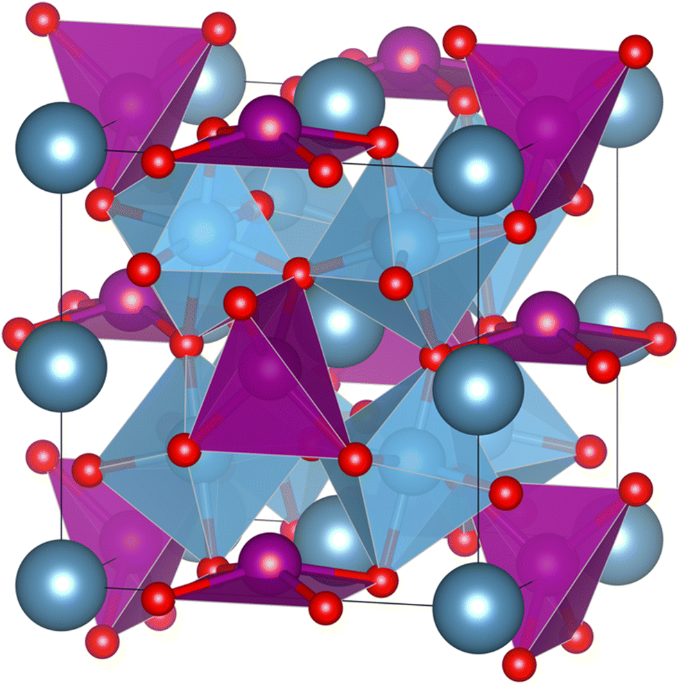 | ||
| Fig. 1 Columnar A-site ordered double perovskite CaMnTi2O6 (P42mc).14 Ca(II) cations are in dark grey-blue, Mn(II) cations and their coordination polyhedra in purple, Ti cations and their coordination polyhedra in blue and O anions in red. The crystal structure illustration has been prepared with the VESTA program.22 | ||
Because CaMnTi2O6 is ferroelectric, it must also exhibit pyroelectric behaviour which has yet not been reported. To find the optimal composition range for the study of pyroelectricity, we investigate here the structural and ferroelectric behaviour of Ca2−xMnxTi2O6 with x = 0, 0.2, 0.3, 0.4, 0.5, 0.6, 0.7, 0.8 and 1. We aim to understand the phase transition from centrosymmetric space group Pbnm (x = 0) to the non-centrosymmetric space group P42mc (x = 1) and the connected change in the ferroelectric properties.
2. Experimental
X-ray diffraction measurements, as well as dielectric measurements were performed on Ca2−xMnxTi2O6 samples with 0 ≤ x ≤ 1. Samples were prepared under high pressure and at high temperatures.2.1. High-pressure synthesis
CaTiO3 (Alfa Aesar, 99+% purity), MnO (Sigma Aldrich, 99% purity), and TiO2 (Alfa Aesar, 99.5% purity) were used as precursors in a ratio according to x. The precursor powders were ground together in ethanol using an agate mortar and pestle. The dried powder mix was lightly pressed into a gold capsule. A cubic anvil geometry was used, for details on the high-pressure setup and sample preparation for the pressing, see ref. 23. The samples were synthesized at 4 GPa pressure. The synthesis temperature was limited by the melting point of the Au capsules at the given pressure, and therefore we aimed at a temperature right below the melting temperature. At temperatures of over 1000 °C, our calibration is not that accurate anymore, and the synthesis temperature of around 1250 °C is an estimate. The samples were held at the high pressure and temperature for 30 minutes, after which they were quenched to room temperature and the pressure was released.2.2. Preparing samples for characterization
For the ferroelectric measurements, smaller discs were cut from the as-synthesized samples with a razor blade. To decrease the thickness of the samples further and to get a smooth and flat surface, the discs were ground with a sandpaper to a thickness between 0.23 mm and 0.55 mm. Disc diameters varied between 2.4 mm and 2.69 mm. In order to release the internal stress from the high pressure synthesis, the sample discs were annealed at 600 °C in oxygen atmosphere for 10 h. DuPot 5065 silver ink electrodes were painted on the discs and cured for 20 minutes between 110 and 120 °C. The part of each sample that was not used for making the discs was ground in an agate mortar to fine powder which was used for powder X-ray diffraction experiments.3. Results and discussion
Samples of Ca2−xMnxTi2O6 with 0 ≤ x ≤ 1 were successfully synthesized, being close to phase pure. Some of the samples showed small (less than 2%) amounts of impurities (TiO2, MnTiO3, CaCO3).3.1. Structural analysis
For the series of compositions Ca2−xMnxTi2O6 from x = 0 (CaTiO3) to x = 1 (CaMnTi2O6), the unit cell volume was expected to decrease as a function of x since the Mn(II) ions gradually replacing the Ca(II) ions are significantly smaller compared to Ca(II) ions (the ionic radius of 12-coordinated Ca(II) is 1.34 Å, and the ionic radius of 4-coordinated Mn(II) is 0.66 Å26). The powder XRD patterns of all samples together with their Rietveld refinements are given in the ESI (Fig. S1–S8†). An explanation for the relatively large χ2 values is the high pressure synthesis method and the internal strain induced by it. The lattice parameters obtained from the XRD analyses are also given in Table S1 of ESI.† Samples with x = 0 to 0.3 were refined in space group Pbnm, while samples with x = 0.4 to 1 could be refined in space group P42mc. The used space group was decided based on a comparison of each diffraction pattern with those of the end members of the series, CaTiO3 (x = 0, Pbnm) and CaMnTi2O6 (x = 1, P42mc), which will be discussed later.In order to compare unit cell volumes, the volume of the unit cells refined in Pbnm was scaled to fit the volume of unit cells refined in space group P42mc. The c lattice parameter is comparable in both space groups, Pbnm and P42mc, but the a and b parameter differ by a factor of about √2. Hence, a total scaling factor of 2 is applied to the volumes of the unit cells refined in Pbnm to match the volumes of the unit cells refined in P42mc. For x = 0.3 and x = 0.4, the Rietveld refinement was carried out in both space groups as parallel refinements. The double unit cell volume for x = 0.3 refined in Pbnm is 443.18 Å3 and the volume in P42mc is very close to it with a value of 443.29 Å3. For x = 0.4, the volumes are 442.39 Å3 and 442.53 Å3 for space groups Pbnm and P42mc, respectively. However, a closer look at the powder X-ray diffraction patterns clearly showed the sample with x = 0.3 to adopt the orthorhombic crystal structure while the sample with x = 0.4 shows features of a tetragonal crystal structure. Fig. S9 in the ESI† shows an example for 2θ around 47.6° where the transition becomes visible. Fig. S10 in ESI† indicates how the ordering in the samples starts at x = 0.4, where a peak around 2θ = 28.5° starts to appear. It is an example of a peak related to A-site cation ordering in space group P42mc.
Fig. 2 shows the resulting relation between the unit cell volume and the increasing amount of Mn(II) substitution described by x in Ca2−xMnxTi2O6. With an increasing amount of Mn(II), the unit cell volume becomes smaller, as expected from the smaller Mn(II) ions replacing the larger Ca(II) ions.
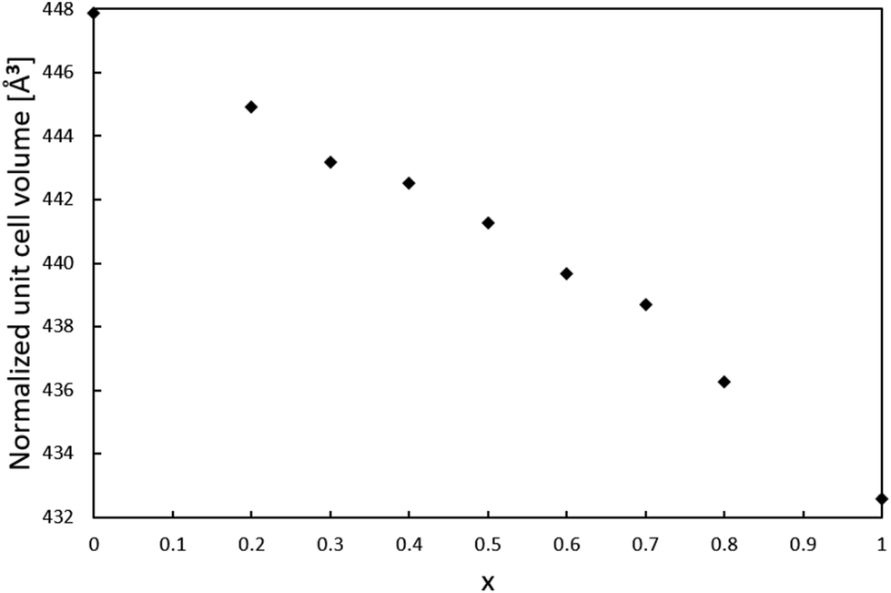 | ||
| Fig. 2 Relation between the unit cell volume and the amount x of Mn(II) substitution in Ca2−xMnxTi2O6. The unit cell volume of phases refined in space group Pbnm has been scaled with a factor 2 to fit the volume of unit cells refined in P42mc. | ||
Since the lattice parameter c spans over two oxygen octahedra in both space groups Pbnm and P42mc, its behavior as a function of x was expected to resemble the behaviour of the unit cell volume. Interestingly, the c lattice parameter was not found to strictly shrink with respect to x. As shown in Fig. 3, the length of the c-parameter decreases as expected in general when moving from x = 0 to x = 1 but suddenly increases between x = 0.3 and x = 0.5, after which the parameter decreases again as expected. No evidence was found in the XRD patterns for a mixed phase of CaTiO3 and CaMnTi2O6 being responsible for the behavior of the c-lattice parameter. The range in which the lattice parameter deviates from the expected behavior indicates the phase transition and is probably connected to the appearance of polarization along the c-axis. As a comparison, Fig. S11 in the ESI† shows the change of the a and b lattice parameters with respect to x. The change could also be observed from the changes seen in the diffraction patterns (Fig. S2 and S3 in the ESI†). Li et al.15 found the intensity of the second harmonic generation to be close to the background for x < 0.315 which indicates the loss of non-centrosymmetry and therefore polarity in the unit cell. This is in line with our observations on the phase transition. Even in the overall unit cell volume in Fig. 2, a slight irregularity is observed around x = 0.4. As discussed above, samples of x = 0.3 and x = 0.4 were refined in both space groups Pbnm and P42mc. The c-parameters of x = 0.3 are 7.623 Å and 7.628 Å, respectively and for x = 0.4 they are 7.635 Å and 7.636 Å, respectively. Even though the difference in space group results in larger differences in the c lattice parameter compared to unit cell volume, still the overall trend of the series remains the same.
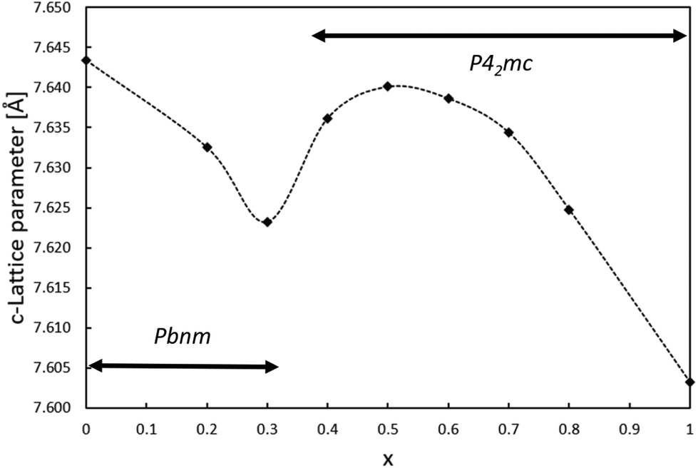 | ||
| Fig. 3 Relation between the lattice parameter c and the amount of Mn(II) substitution in Ca2−xMnxTi2O6. | ||
The phase transition is evident in the change of the main peak area in the powder diffraction patterns, around 2θ = 33° (Fig. 4). When x changes from 0 to 1, the position of the main peak shifts only slightly due to the change in lattice parameters but the two neighboring peaks in CaTiO3 first vanish and then the side peak of CaMnTi2O6 emerges. With the unit cell, also the Miller indices of the peak change from (112) in CaTiO3 (Pbnm) to (202) in CaMnTi2O6 (P42mc). From Fig. 4 it is clear that the phase transition must occur between x = 0.3 and x = 0.4 where there are no distinct peaks visible. As discussed above, another example of a clear change in the XRD patterns indicating the phase transition is the appearance of the (112) and (121) peaks around 2θ = 28.6° in the sample with x = 0.4 (Fig. S10 in the ESI†).
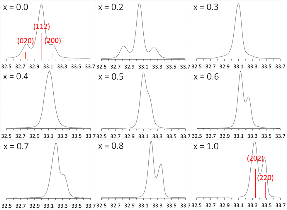 | ||
| Fig. 4 Changes in the main peak area, around 2θ = 33° in the powder diffraction pattern of Ca2−xMnxTi2O6 from CaTiO3 (x = 0) to CaMnTi2O6 (x = 1). The Miller indices of the main peak of x = 0 (Pbnm) are (112) and the ones on the side (020) and (200), depending on the orientation. For x = 1 (P42mc), the main peaks are (202) and (220). | ||
3.2. Density
The average density of an as-synthetized Ca1.5Mn0.5Ti2O6 sample from ten volume measurements is 4.09 g cm−3 which corresponds to a relative density of over 97%. The high density is to be expected for samples synthesized under high pressure and due to the robustness of the synthesis method we assume all samples in the studied series to have a similarly high density. The density measurement provides no information of possible pores in the sample since the gas of the pyctometric measurement penetrates into these.3.3. Ferroelectric analysis
The samples in general were rather unstable under electric field and had a tendency to break down during measurements before saturation was reached. An explanation of the weak resistance against breakdowns can be found in the synthetic approach. Even though the samples have been heat treated afterwards, there is a possibility of remaining stress due to the high pressure during the synthesis process. Additionally, the samples are rather brittle which makes them even more susceptible towards a breakdown in medium to high electric fields. In those cases where the sample was able to withstand higher electric fields, saturation in the hysteresis polarization curve was not reached because of the sample thickness and the maximum voltage of the measurement setup was limited to 4 kV. Samples were too brittle to be prepared thinner in order to achieve higher fields. The numbers mentioned in the following discussion are for the purpose of comparison and neither the true remanent polarization nor the true coercive field.As expected from the structural data, the sample with x = 0.2 basically shows linear behavior in a P–E measurement. Since the sample still adopts the centrosymmetric structure of CaTiO3, no remanent polarisation can be measured. The sample with x = 0.4, which was refined in the non-centrosymmetric space group P42mc still exhibits more or less linear behaviour but with a slight hysteresis starts to emerge. This, again, indicates a smooth structural transition around this composition rather than a sudden switch between space groups Pbnm and P42mc. Both P–E measurements for x = 0.2 and x = 0.4 are shown in Fig. 5. For comparison, they are both shown with a maximum field of about 5 V μm−1. The hysteresis curve of the x = 0.4 sample with a maximum field of 15 V μm−1 is available in ESI as Fig. S12.†
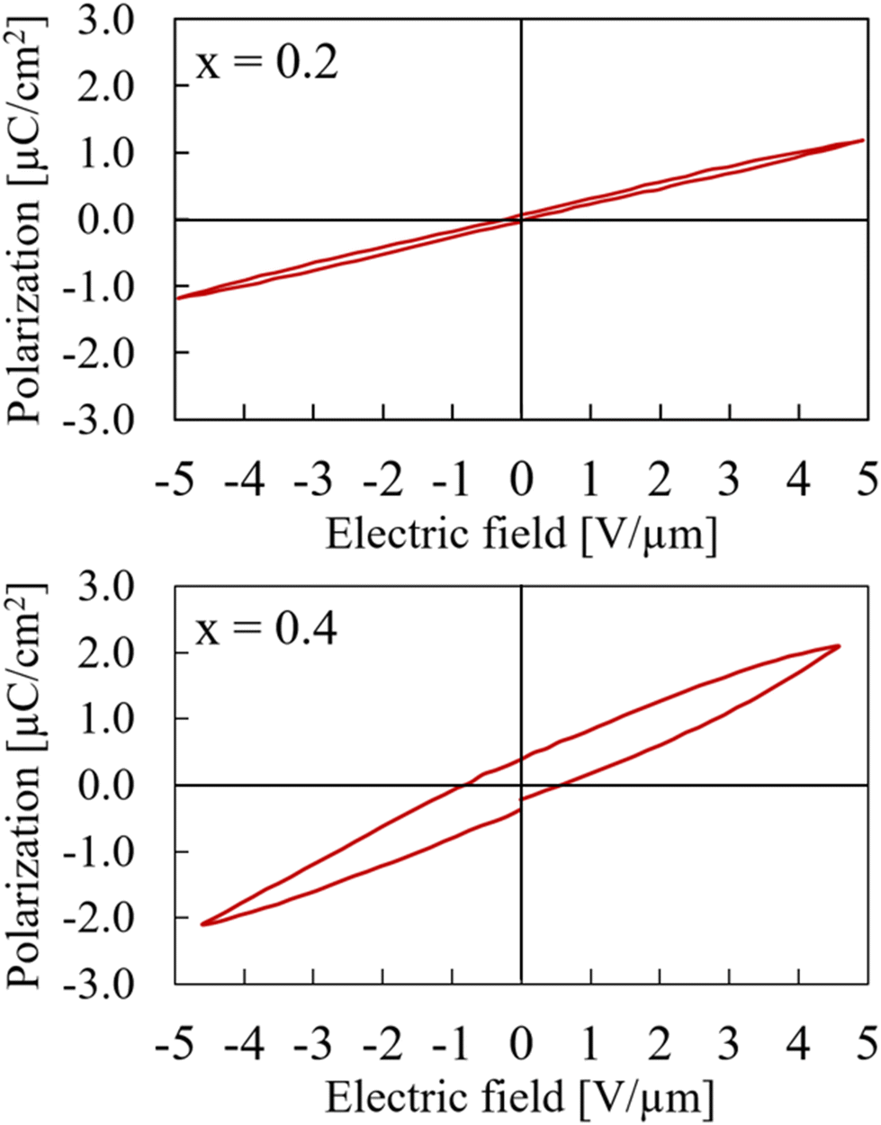 | ||
| Fig. 5 Hysteresis curves of Ca2−xMnxTi2O6 with x = 0.2 (upper) and x = 0.4 (lower) at maximum electric field of 5 V μm−1. | ||
Samples with x between 0.5 and 1 adopt the non-centrosymmetric CaMnTi2O6 structure based on the XRD analysis and therefore a ferroelectric hysteresis loop should be detected. However, this is only the case for x = 0.5 and x = 0.6. The hysteresis curves are shown in Fig. 6. The measurement with x = 0.6 has a higher zero-field polarization Pr = 3.11 μC cm−2 as well as a higher zero-polarization field Ec = 4.78 V μm−1. Pr for the sample with x = 0.5 is determined to be only 1.62 μC cm−2 and Ec = 3.17 V μm−1. Because the sample x = 0.6 had a breakdown after 12 V μm−1, the comparison in Fig. 6 is shown for a maximum field of 12 V μm−1, even though it was possible to measure the x = 0.5 sample up to the device limit of 15 V μm−1.
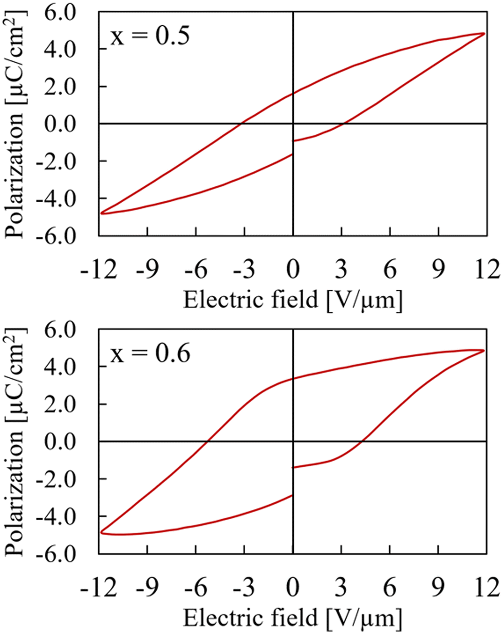 | ||
| Fig. 6 Hysteresis curves of Ca2−xMnxTi2O6 with x = 0.5 (upper) and x = 0.6 (lower) at maximum electric field of 12 V μm−1. | ||
Interestingly, the polarization measurements of the samples with x = 0.7, x = 0.8, and x = 1.0 all display large leakage currents and respond like a highly leaking capacitor (slight linearity in polarization).(Fig. 7). Especially for the x = 1.0 sample, which is pure CaMnTi2O6, the result differs from literature reports where ferroelectric hysteresis loops for fields up to 20 V μm−1 were measured.14 However, our samples with x = 1.0 always contained at least a small amount of single crystals which were loosely packed together with the bulk material. The sample seemed more crumbly than those with smaller x. The single crystals were detected amongst the regular powder particles after grinding the sample as preparation for XRD measurements. Aimi et al. do not report any single crystals in the samples used for polarization measurements. While the pressed bulk sample has a high relative density, the connection of single crystals to the bulk is rather loose. This leads to resistor-like behaviour. However, the x = 1.0 sample showed a mixture of hysteresis and resistor-like behaviour at smaller maximum fields (Fig. S13 in ESI†).
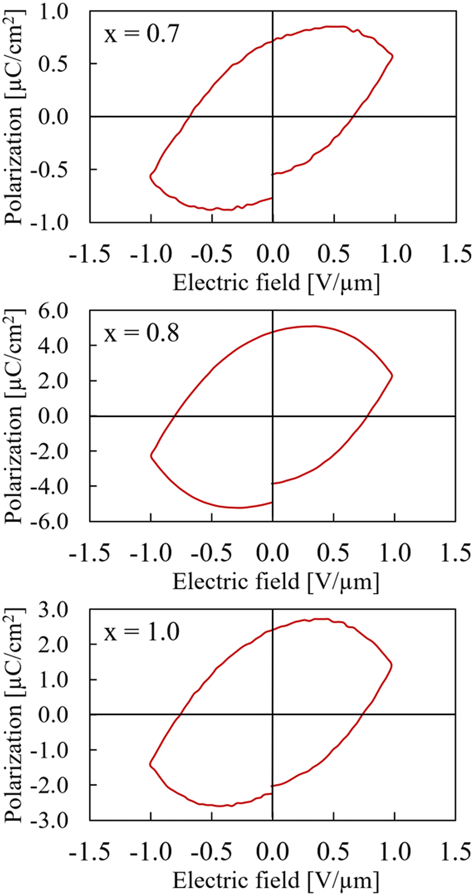 | ||
| Fig. 7 Hysteresis curves of Ca2−xMnxTi2O6 with x = 0.7 (upper), x = 0.8 (middle), and x = 1.0 (lower) at maximum electric field of 1 V μm−1. Note that the polarization axes have different scales. | ||
4. Conclusions
We have synthesized samples of Ca2−xMnxTi2O6 with x = 0.2; 0.3; 0.4; 0.5; 0.6; 0.7; 0.8; and 1.0. A structural analysis of these samples identified the phase transition between the centrosymmetric space group Pbnm of x = 0 (CaTiO3) and the non-centrosymmetric space group P42mc of x = 1 (CaMnTi2O6) to be around x = 0.4. This has been shown in the change of the XRD pattern around the main peak at a 2θ of about 33° and the non-linear change in the c lattice parameter. While the lattice parameters are expected to shrink from x = 0 to x = 1 due to substitution of the larger Ca(II) ions by the smaller Mn(II) ions, the c lattice parameter increases between x = 0.3 and x = 0.5. P–E measurements also confirmed a linear behaviour for x = 0.2 and a clear hysteresis and therefore ferroelectricity for x = 0.5 and 0.6. However, for x = 0.7 and higher, no hysteresis was measured but rather resistor-like behaviour. With our synthesis and characterization methods, a composition of Ca2−xMnxTi2O6 with x = 0.6 appears to lead to the strongest ferroelectricity. However, it can be expected that the zero-field polarization and the zero-polarization field further increase in samples of x = 0.7 to 1.0. Therefore, no final conclusion can be made about the optimal composition of Ca2−xMnxTi2O6 for ferroelectric purposes. The samples with x > 0.7 behave like resistor and do not show their whole ferroelectric and therefore pyroelectric potential due to a poor coupling between formed single crystals and the bulk sample. It was not possible to completely avoid the formation of single crystals during the synthesis of samples with large x. A detailed investigation on the formed single crystals will be provided elsewhere.Author contributions
Elisabeth K. Albrecht: Conceptualization; investigation; visualization; writing – original draft preparation; writing – review and editing. Tuomo Siponkoski: Investigation (ferroelectric measurements); writing – review and editing. Eeva-Leena Rautama: Investigation (Rietveld refinement); writing – review and editing. Maarit Karppinen: Resources; writing – review and editing. Antti J. Karttunen: Conceptualization; writing – review and editing; supervision; funding acquisition. All authors have read and agreed to the published version of the manuscript.Conflicts of interest
There are no conflicts to declare.Acknowledgements
We thank Dr Benjamin Wilson (Aalto University) for his help in pycnometric volume determination of our samples, Dr Girish Tewari (Aalto University) for the preparation of the samples for electrical measurements, and Dr Taneli Tiittanen (Aalto University) for his help in setting up the high-pressure experiments. We acknowledge funding from the Research Council of Finland (grant no. 317273) and the Finnish Cultural Foundation. We thank CSC – The Finnish IT Center for Science for computational resources and RawMatTERS Finland Infrastructure (RAMI) at Aalto University.References
- V. Veerapandiyan, F. Benes, T. Gindel and M. Deluca, Materials, 2020, 13, 5742 CrossRef CAS PubMed.
- P. Gao, Z. Liu, N. Zhang, H. Wu, A. A. Bokov, W. Ren and Z.-G. Ye, Chem. Mater., 2019, 31, 979–990 CrossRef CAS.
- J. F. Nye, Physical properties of solids, Oxford University Press, 1957 Search PubMed.
- K. M. Ok, E. O. Chi and P. S. Halasyamani, Chem. Soc. Rev., 2006, 35, 710 RSC.
- R. J. D. Tilley, Perovskites: structure-property relationships, Wiley, Chichester, West Sussex, United Kingdom, 1st edn, 2016 Search PubMed.
- P. M. Woodward, Acta Crystallogr., Sect. B: Struct. Sci., 1997, 53, 32–43 CrossRef.
- P. M. Woodward, Acta Crystallogr., Sect. B: Struct. Sci., 1997, 53, 44–66 CrossRef.
- G. King and P. M. Woodward, J. Mater. Chem., 2010, 20, 5785 RSC.
- A. Bokov, N. Protsenko and Z.-G. Ye, J. Phys. Chem. Solids, 2000, 61, 1519–1527 CrossRef CAS.
- B. Jaffe, W. R. Cook and H. L. Jaffe, Piezoelectric ceramics, Academic Press, London, New York, 1971 Search PubMed.
- S. Zhang, R. Xia and T. R. Shrout, J. Electroceram., 2007, 19, 251–257 CrossRef CAS.
- T. R. Shrout and S. J. Zhang, J. Electroceram., 2007, 19, 113–126 CrossRef.
- J. Jia, S. Guo, S. Yan, F. Cao, C. Yao, X. Dong and G. Wang, Appl. Phys. Lett., 2019, 114, 032902 CrossRef.
- A. Aimi, D. Mori, K.-I. Hiraki, T. Takahashi, Y. J. Shan, Y. Shirako, J. Zhou and Y. Inaguma, Chem. Mater., 2014, 26, 2601–2608 CrossRef CAS.
- Z. Li, Y. Cho, X. Li, X. Li, A. Aimi, Y. Inaguma, J. A. Alonso, M. T. Fernandez-Diaz, J. Yan, M. C. Downer, G. Henkelman, J. B. Goodenough and J. Zhou, J. Am. Chem. Soc., 2018, 140, 2214–2220 CrossRef CAS PubMed.
- J. Ruiz-Fuertes, T. Bernert, D. Zimmer, N. Schrodt, M. Koch-Müller, B. Winkler, L. Bayarjargal, C. Popescu, S. MacLeod and K. Glazyrin, Phys. Rev. B, 2017, 96, 094101 CrossRef.
- G. Gou, N. Charles, J. Shi and J. M. Rondinelli, Inorg. Chem., 2017, 56, 11854–11861 CrossRef CAS PubMed.
- J. Herrero-Martín, J. Ruiz-Fuertes, T. Bernert, M. Koch-Müller, E. Haussühl and J. L. García-Muñoz, Phys. Rev. B, 2018, 97, 235129 CrossRef.
- R. A. Maier, K. F. Garrity, A. Ozarowski, M. P. Donohue, G. Cibin and I. Levin, Acta Mater., 2021, 207, 116688 CrossRef CAS.
- A. M. Glazer, Acta Crystallogr., Sect. B: Struct. Crystallogr. Cryst. Chem., 1972, 28, 3384–3392 CrossRef CAS.
- E. K. Albrecht and A. J. Karttunen, Dalton Trans., 2022, 51, 16508–16516 RSC.
- K. Momma and F. Izumi, J. Appl. Crystallogr., 2011, 44, 1272–1276 CrossRef CAS.
- L. Sederholm, T. Tiittanen and M. Karppinen, J. Solid State Chem., 2023, 317, 123646 CrossRef CAS.
- J. Rodríguez-Carvajal, Phys. B, 1993, 192, 55–69 CrossRef.
- T. Roisnel and J. Rodriguez-Carvajal, Proceedings of the Seventh European Powder Diffraction Conference (EPDIC 7), 2000, pp. 118–123.
- R. D. Shannon, Acta Crystallogr., Sect. A: Cryst. Phys., Diffr., Theor. Gen. Crystallogr., 1976, 32, 751–767 CrossRef.
Footnote |
| † Electronic supplementary information (ESI) available: Additional P–E curves, lattice parameters of the studied materials, and Rietveld refinements of powder XRD patterns. See DOI: https://doi.org/10.1039/d4dt00360h |
| This journal is © The Royal Society of Chemistry 2024 |