 Open Access Article
Creative Commons Attribution 3.0 Unported Licence
Strategies to improve the mechanical robustness of metal halide perovskite solar cells†
Muzhi
Li
a,
Samuel
Johnson
b,
Lidon
Gil-Escrig
c,
Maayan
Sohmer
d,
Carlos A.
Figueroa Morales
e,
Hongki
Kim
e,
Siraj
Sidhik
f,
Aditya
Mohite
 f,
Xiwen
Gong
e,
Lioz
Etgar
 d,
Henk J.
Bolink
 c,
Axel
Palmstrom
g,
Michael D.
McGehee
b and
Nicholas
Rolston
 *a
*a
aArizona State University, Tempe, Arizona 85281, USA. E-mail: nicholas.rolston@asu.edu
bUniversity of Colorado Boulder, Boulder, Colorado 80309, USA
cUniversity of Valencia, Valencia, 46003, Spain
dThe Institute of Chemistry, The Center for Nanoscience and Nanotechnology, Casali Center for Applied Chemistry, The Hebrew University of Jerusalem, Jerusalem, 91904, Israel
eUniversity of Michigan, Ann Arbor, Michigan 48109, USA
fRice University, Houston, Texas 77251, USA
gNational Renewable Energy Laboratory, Golden, Colorado 80401, USA
First published on 4th December 2023
Abstract
We report on the mechanical properties of high-efficiency perovskite solar cells (PSCs) with different chemical components by measuring the fracture energy (Gc) of films and devices. With the help of both macroscopic and microscopic techniques, we identify the locations where fracture takes place in the devices (either adhesive or cohesive failure) with various material and device structures. We propose strategies that can improve the fracture energy of PSCs based on the measured Gc: the use of ozone-nucleated atomic layer deposition to improve charge transport layer robustness and the use of 2D perovskites and morphology control to improve the perovskite robustness. Our findings offer a pathway to rationally study the mechanical properties of PSCs and enable such cells to be more mechanically robust to reach commercial viability.
I. Introduction
The power conversion efficiency (PCE) of perovskite solar cells (PSCs) has substantially increased to a record of 26.08%.1 In order to achieve operational stability and long-term reliability, however, solar cells are required to be not only highly efficient but mechanically robust. Previous work has shown that environmental stressors, such as light illumination, can induce significant degradation in device efficiency due to mechanical failure.2,3 Thermal cycling also plays a key role, as PSCs consist of various thin film layers with different thermal expansion coefficients, which leads to the development of stress from thermal processing or heating during operation. These layers are weakly bonded to each other4 based on low adhesion, making them susceptible to strain-induced delamination. The large stresses and weak bonding in the films and/or interfaces can lead to mechanical failure at both the material and the device level.5 Such failures, including fracture and delamination, further accelerate environmental degradation and result in a loss of ohmic contact, which in turn compromises the PCE and ultimately leads to device failure. Other critical factors such as ion migration, hysteresis, and defect formation also play key roles in degradation, however their connection to mechanical failures is still unknown.There are synergistic environmental and mechanical stresses which occur in operation that are not probed during individual stress tests and the degradation modes in perovskites are different than that of silicon PV. Unfortunately, the only series of accelerated tests are not based on individual factors and are provided by the International Electrotechnical Commission (IEC) and aim to uncover individual factors related to the reduction of the service life for PV modules.6 Static and dynamic mechanical load tests as well as hail tests are included in the IEC 61646 thin film qualification tests that were designed for silicon PV, which include temperature cycling, humidity freeze, and damp heat accelerated exposures. Such tests currently are the only set of standards for perovskite modules to be mechanically stable enough to consistently operate in the field. Nonetheless, these tests alone are not sufficient to ensure that perovskite modules will reach the targeted 20-year service lifetimes to be competitive with incumbent PV technology. Systematical characterizations to reveal the link between mechanical properties and device stability is relatively scarce, which limit the rational design for stable PSCs.
To better understand and study the mechanical properties of PSCs, fracture energy (Gc), an indicator to evaluate the robustness of materials, was used. Gc is the energy required to open a unit area of crack, and the two contributions of Gc come from plastic deformation and atomic bond breakage. For robust materials, such as PV encapsulants or metals, the former is the main component of the Gc, often in the range of thousands of J m−2 and above! However, the energy to break atomic bonds is much lower, and this is the dominant component for PSCs due to their intrinsically fragile and brittle nature. Additionally, given the weak ionic bonding of perovskites, the bond breakage energy of perovskites is comparable to table salt. Previously, the fracture energy of a wide range of PSCs was investigated and the results showed that the Gc values of PSCs are commonly below 1.5 J m−2, which are significantly lower than c-Si cells (∼10–200 J m−2).7 In mixed-cation perovskites that incorporated cesium (Cs) and formamidinium (FA), the decreased grain size and impurities between grain boundaries resulted in a reduced Gc of MA/FA, Cs/FA, and Cs/FA/MA devices.8 Some strategies for increasing perovskite Gc included the use of externally reinforcing scaffolds,9 polymeric additives,10,11 and grain boundary engineering12/toughening approaches.13 However, these were mostly done for MAPbI3-based perovskites that are no longer favored in the perovskite community due to chemical instability. Additionally, there has been limited progress on improving the highly fragile, small molecule-based (fullerenes, spiro-OMeTAD, Li-based dopants) charge transport layers (CTLs) and additives that often have even lower Gc values than perovskites.
In this work, we study the mechanical integrity of metal halide PSCs with updated, state-of-the-art structures and compositions. The goal was to improve the mechanical robustness of PSCs through strategies that incorporate molecules with improved bonding and/or deformability. We found that (1) the widely used fullerene layer in PSCs can be strengthened by adding ozone nucleation-treated tin oxide buffer layer, (2) the vacuum-evaporated MA-based and Cs-FA mixed-cation perovskites have relatively low Gc values due to their high grain boundaries and small grains, (3) two-dimensional (2D) Ruddlesden–Popper (RP) perovskites with n-butylammonium (BA) and benzylammonium (Bnz) spacer cations both have higher Gc values through the increase in plastic deformation for lower n-values. This understanding of how such materials influence the Gc of PSCs is studied in this work for the first time.
II. Methods
The perovskite samples for fracture testing were all deposited on glass substrates as full devices or partial stacks with or without CTLs. To create a double cantilever beam (DCB) fracture sample, a layer of thin epoxy was applied to another identical glass superstrate and then bonded to the device/stack (Fig. 1a) to create a sandwich-like structure with the device layers bonded between glass. The epoxy was cured at room temperature to create the DCB structure in Fig. 1b. It is important to note that all samples had a length of at least 3 cm to ensure enough area to create a beam without reaching the edges of the sample.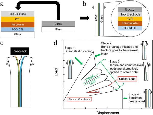 | ||
| Fig. 1 Schematic illustrations of (a) DCB sample fabrication method, (b) General DCB sample structure (c) Precrack (d) Load–displacement response of an ideal fracture energy measurement. | ||
By using a DCB configuration in the delaminator adhesion test system (DTS, Menlo Park, CA), measurement of the critical load needed for fracture propagation can be realized along with the value of Gc. A precrack is introduced to the DCB samples by carefully inserting the tip of a razor in between the two glass substrates to propagate the initial crack (Fig. 1c). In the measurement, as shown in Fig. 1d, DCB samples are pulled apart by an electric actuator with a constant displacement rate. The displacement rate is the velocity of the actuator moving in the direction in which the DCB specimens are pulled apart. The resulting load generated by this change in displacement is measured with the load. At stage I, a uniaxial tensile load is applied to the sample, and a linear loading curve is observed until the initial precrack starts to extend, generating a decrease in the load at stage II. This decrease in load corresponds to the critical load where crack propagation initiates. Once a decrease in the load–displacement plot is observed, the specimen is partially unloaded and then subjected to more loading and unloading cycles at stage III until the crack spreads through the entire length of the thin film structure. It is important to note that the sample is always loaded under uniaxial tensile force until it breaks. The weakest interface or layer in the device is determined after the DCB sample breaks apart fully at stage IV. The value of Gc is then calculated for each critical load and averaged to obtain multiple data points per specimen in the following equation:8,14
 | (1) |
The crack length was estimated by a compliance method:
 | (2) |
In this work, we tested a large number of p–i–n devices and film stacks with various chemistries for the CTLs and perovskites to determine strategies for increasing the fracture energy. The key take-aways are reported below.
III. Results and discussion
Challenges in transport layers and improving fullerene mechanical fragility
In a DCB test, the fracture path occurs adhesively at the weakest interface, cohesively within the weakest layer, or through a combination of the two. Here, we first studied the Gc of p–i–n devices with MAPbI3 and MAPb(I0.9Br0.1)3 as the absorber layers and found that the crack propagated cohesively either in the organic P or N CTLs (Fig. 2a and Fig. S2, ESI†), but mainly in C60 layer, with a Gc of 0.23 ± 0.15 J m−2 and 0.16 ± 0.03 J m−2 for MAPbI3 and MAPb(I0.9Br0.1)3 samples, respectively, showing that the CTL tends to be the weakest in the p–i–n device stack. Compared with the Gc of crystalline silicon (10–200 J m−2) and organic PV (∼5 J m−2), the p–i–n devices in this work are considered to be extremely fragile (Fig. 2b). The fragility of organic CTLs has been studied previously,7 and in most p–i–n devices, there is an increase in Gc when using inorganic layers (i.e., NiOx) and undoped polymers (i.e., PTAA, poly-TPD, PEDOT:PSS) that are comparably more mechanically robust than small molecules.15–22 The TaTm/F6TCNNQ small molecule structure is therefore not ideal from a mechanical perspective (Gc of 0.57 ± 0.19 J m−2, Fig. S3, ESI†).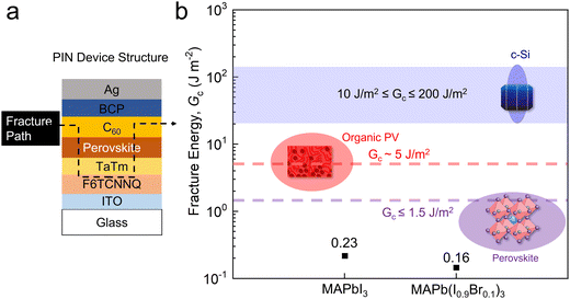 | ||
| Fig. 2 (a) Device structure and fracture path. (b) The measured average Gc of the p–i–n samples with MAPbI3 and MAP(I0.9Br0.1)3 in comparison with the Gc of various PV technologies. | ||
However, almost all p–i–n devices use a C60 layer to prevent perovskite degradation when depositing the N-type CTL.23–29 There have been only a few reports of fully inorganic CTL devices with high power conversion efficiencies exceeding 20%,30,31 and these are not possible for stable tandem structures that require a sputtered top transparent conducting electrode. Tin oxide is the most common buffer layer for these top conductive electrodes and to improve device stability. In order to reinforce the C60 layer, adding a tin oxide buffer layer enabled by atomic layer deposition (ALD) with good adhesion can not only boost cell efficiency but improve the operational and mechanical stability of perovskite devices.32,33 However, previous work showed that peel-off tests on p–i–n perovskite/silicon tandem solar cells delaminated at the interface of C60 and SnOx, demonstrating the fragility of the bonding between C60 and SnOx.34
To address the C60 mechanical fragility, we performed fracture energy measurements on samples consisting of glass/ITO/perovskite/C60/ALD-SnOx/Ag. The results confirmed the weak bonding at the C60/ALD-SnOx interface with a low Gc of 0.68 ± 0.18 J m−2. In order to understand the delamination mechanism, the C60/ALD-SnOx interface was investigated by scanning transmission electron microscope (STEM) and the cross-sectional STEM images show numerous vertical microscopic cracks at the interface (Fig. S4, ESI†), which can readily initiate the delamination of the C60 and ALD-SnOx under mechanical loads.
By treating the ALD-SnOx capping layer above C60 with ozone and water,35 a higher contact area can be achieved due to fewer cracks at the interface (Fig. S4b, ESI†). This can be ascribed to the fact that the nucleation of the ALD process on the C60 surface was improved by the ozone treatment, which makes the surface chemistry more reactive to the ALD-SnOx, allowing for the formation of Sn–O–C60 bonds. Besides, the added ozone may also polymerize and cross-link C60, enabling ALD-SnOx and C60 to form stronger bonding. To verify if the improvement in the interface morphology can result in higher mechanical robustness, fracture energy measurements were performed on samples with ALD-SnOx layers that were treated with or without the aforementioned ozone nucleation process. A relatively low Gc (0.39 ± 0.11 J m−2) and an adhesive failure at the C60/ALD-SnOx interface were observed for control samples, while there was a higher Gc (0.58 ± 0.12 J m−2) and a meandering fracture path in the C60 layer for the samples with ozone nucleation treatment (Fig. 3 and Fig. S5, ESI†). The higher Gc value and the meandering fracture path in the C60 layer of ozone-nucleated samples strongly suggest that the ozone nucleation treatment effectively improves the C60/ALD-SnOx adhesion.
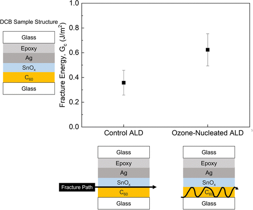 | ||
| Fig. 3 A comparison between the average Gc results and fracture paths of control ALD-SnOx and Ozone-nucleated ALD-SnOx samples. | ||
We also tested film stacks with perovskite (glass/ITO/perovskite/C60/ALD-SnOx/Ag) and observed that the fracture occurred cohesively within the perovskite, fracturing at 1.12 ± 0.34 J m−2, compared to the control stacks (glass/ITO/perovskite/C60/Ag) where the fracture involved the C60 layer, failing at 0.68 ± 0.18 J m−2 (Fig. S6, ESI†). This indicates that the ALD-SnOx can reinforce the C60 and that the perovskite becomes the weakest layer in the device stack. As such, we focus on strategies to improve perovskite mechanical robustness for the rest of this study.
Challenges in active layer and improving perovskite mechanical fragility
Vacuum evaporation has been considered one of the most promising solutions to solve PSC scaling challenges.36–38 However, little is known about the mechanical properties of vacuum-evaporated perovskites. Here, we studied the fracture resistance of vacuum-evaporated MAPb(I0.9Br0.1)3 and FA0.74Cs0.26Pb(I0.86Br0.14)3 with the sample layout that comprised glass/ITO/perovskite/Ag. All samples failed cohesively in the perovskite layers with low Gc values ranging from 0.87 J m−2 to 0.53 J m−2 (Fig. 4 and Fig. S7, ESI†), indicating weak bonding in the perovskite films. A relatively lower Gc value in the FACs-based samples is due to the smaller grain size and higher density of grain boundary in the film. To better understand the delamination process in the vacuum-evaporated perovskite, we investigated the morphology of the perovskite film with scanning electron microscopy (SEM). The cross-sectional SEM images show fine grains and a high density of grain boundaries (GBs) in the vacuum-evaporated perovskite film, indicating that microscopic cracks can easily be initiated by those GBs under stresses and spread to the rest of the film, which causes cohesive failure in the devices. Therefore, coarse, large-grained perovskites (with sizes comparable to the film thickness) are preferred for mechanically robust PSCs. Moreover, our results are in accordance with a previous study on the relationship between the mechanical reliability of perovskite thin films and their grain morphology.12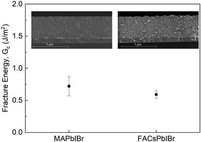 | ||
| Fig. 4 The measured Gc of vacuum-evaporated MAPb(I0.9Br0.1)3 and FA0.74Cs0.26Pb(I0.86Br0.14)3 perovskites (inset: cross-sectional SEM image of the perovskite layer). | ||
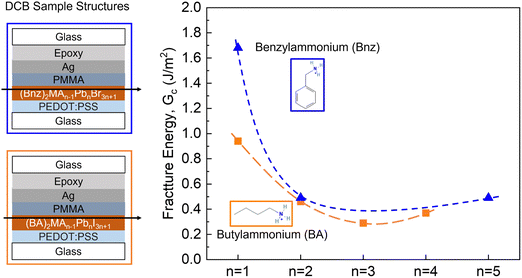
In previous studies, PSCs with mixed cations of n-butylammonium (BA) and MA were more mechanically robust than single-cation perovskites due to the larger size of BA and the possibility of the 2D cation increasing the film plasticity.8 Here, we tested the pure 2D benzylammonium (Bnz)-based and BA-based Ruddlesden–Popper (RP) perovskite devices that adopt the chemical formula of A2MAn−1PbnI3n+1 (n = 1, 2, 3, 4 and 5), where A is an organic spacer cation, and the structure as glass/PEDOT:PSS/perovskite/PMMA/Ag. PMMA and Ag are coated on top of the perovskite as a protective layer against epoxy. The images of fractured samples and fracture energy results are shown in Fig. 5 and Fig. S8, S9 (ESI†). The fracture energy decreases as the thickness of the inorganic layer (n) increases.
For the BA-based samples with n = 1, the fracture happened at the interface between Ag/PMMA and the fracture energy of BA2PbI4 is higher than the measured value (0.94 J m−2), indicating that the cohesion of BA2PbI4 thin film is more robust than the measured Ag/PMMA adhesion (Fig. S8, ESI†). A thin layer of perovskite was attached to the PMMA when fracture propagated in n = 2 and n = 3 samples. Meanwhile, we found a substantial amount of perovskite remained on both sides of the fractured n = 4 samples, suggesting that the perovskite layer was more mechanically fragile, which is in line with the low Gc of 0.37 ± 0.22 J m−2 and can be ascribed to the weak van der Waals bonds in RP perovskites. A downward trend in Gc values with the increasing n-value was observed for both BA-based and Bnz-based 2D RP perovskites as the material properties become more similar to the 3D perovskite structure (Fig. S9, ESI†).
The incorporation of additives can significantly affect several critical aspects of perovskites, such as crystallization, film formation, defect passivation and crystal structure. Nonetheless, the impact of additives on the mechanical integrity of perovskites has not been thoroughly explored. Fracture energy tests were performed on the quasi-2D perovskite PEA2Cs1.6MA0.4Pb3Br10 (PEA = phenethylammonium) with small-molecule additives, such as phosphine oxide (P) and tocylate (T) that have a small molecular weight (≤1000 Da). The incorporation process of the aforementioned additives in the 2D perovskite films is schematically shown in the Fig. S10 (ESI†). Adhesive failures at the interface of perovskite/PMMA were observed for the samples with no additive (Gc = 1.26 ± 0.26 J m−2), while cohesive failure in the perovskite layers occurred when small-molecule P and T additives were added in the perovskites (Fig. S11, ESI†). The Gc decreased to 0.74 ± 0.18 J m−2 (with P only) and 0.49 ± 0.14 J m−2 (with P and T), as shown in Fig. 6. The decrease in the Gc values with the incorporation of additives, along with the cohesive failures, indicates that the small-molecule additives in perovskites can hinder the robustness of perovskite layers due to their weak bonding and lack of deformability despite a similar morphology with additives (Fig. S12, ESI†). A similar effect has been observed for commonly used Li-based (LiTFSI) dopants added to HTLs in n–i–p PSCs.39
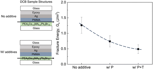 | ||
| Fig. 6 The measured Gc values as a function of the incorporation of small molecule additive phosphine oxide (P) and tocylate (T) in the perovskite layer. | ||
IV. Conclusion and outlook
In summary, we have shown that the CTLs are primarily the weakest element in the p–i–n perovskite device stacks. As a common material used for ETL, C60 has been proven that a layer of ALD-SnOx with ozone nucleation process can increase its Gc value and relocate the fracture to the next weakest layer in the stack, the perovskite. Furthermore, we found that vacuum-evaporated perovskites that have fine grains and a high density of GBs are not ideal for mechanically robust PSCs. Our investigation of the impact of small-molecule additives on the Gc values of perovskite films demonstrated that those small-molecule additives are fragile and capable of reducing Gc. Therefore, the key strategies to increase Gc are (1) to use of ALD-SnOx treated with ozone nucleation process to reinforce C60 (with the eventual goal of replacing C60 and any organic small molecules in CTLs and in the perovskite), (2) to use of 2D perovskites to increase plasticity and control of morphology through processing strategies.This work considered a specific subset of mostly p–i–n perovskite devices where fragility was dominated by the CTL or the perovskite. However, we hope to provide a broader context here that can provide insights into each of the layers and interfaces of a typical perovskite device and module.
Bottom TCO layer
This is not a source of mechanical fragility; however, there are considerations related to the brittleness of crystalline ITO (source) which leads to fracturing in flexible devices at low bending radii.40 This is a consideration for flexible devices but not critical for rigid devices. To mitigate this effect, the use of more amorphous TCOs enables higher flexibility.TCO-HTL
Not a source of delamination or mechanical fragility to the best of our knowledge.HTL-perovskite
Surface roughness plays a role as well as interfacial adhesion; however, we did not observe delamination at this interface because the perovskite layer and perovskite-ETL interfaces were more fragile.Perovskite
Grain size is an important consideration (larger grains and more coarse) to improve fracture energy.Perovskite-ETL
Needs the most improvement, and ideally C60/fullerene-based ETLs would be replaced entirely.ETL-top electrode
Metals (especially Au) do not bond well to materials and ideally would be replaced by carbon or top TCOs.Top electrode-encapsulation
Although adhesion is not a concern, there have been reports of pressure-induced delamination (e.g., encapsulant peeling off the top electrode).41,42Lastly, note that scribe lines present an additional interface and serve as a catalyst for delamination in some package configurations. These effects of monolithic integration are not well understood from a mechanical standpoint and are outside the scope of this work, but this is a key area that we are presently investigating in detail.
Author contributions
Conceptualization, M. L. and N. R.; methodology, M. L. and N. R.; validation, M. L.; formal analysis, M. L.; investigation, M. L. S. J., L. G. E., M. S., C. A. F. M., H. K. and S. S.; resources, S. J., L. G. E., M. S., C. A. F. M., H. K. and S. S.; data curation, M. L., S. J., and L. G. E.; writing – original draft presentation, M. L. and N. R.; visualization, M. L. and N. R.; supervision, A. M., X. G., L. E., H. J. B., A. P., M. D. M., N. R.; project administration, N. R.; funding acquisition, A. M., X. G., L. E., H. J. B., A. P., M. D. M., N. R. All authors have read and agreed to the published version of the manuscript.Conflicts of interest
There are no conflicts to declare.Acknowledgements
N. R. acknowledges support from the Oak Ridge Associated Universities FY2022 Ralph E. Powe Junior Faculty Enhancement Grant Award: Nicholas Rolston: Control of Ion Motion in Halide Perovskite Photovoltaics for Improved Reliability. H. J. B. acknowledges financial support of the European Research Council (ERC) under the European Union's Horizon 2020 research and innovation programme (Grant agreement no. 834431), and LGE acknowledges financial support Ministry of Science and Innovation (MCIN), and the Spanish State Research Agency (AEI): grant IJCI-2019-039851-I. The authors acknowledge support from the Advanced Electronics and Photonics Core Facility at Arizona State University. The authors also acknowledge the use of facilities within the Eyring Materials Center at Arizona State University supported in part by NNCI-ECCS-1542160. This material is based upon work supported by the U.S. Department of Energy’s Office of Energy Efficiency and Renewable Energy (EERE) under Solar Energy Technologies Office (SETO) Agreement Number DE-EE0010502.References
- J. Park, J. Kim, H.-S. Yun, M. J. Paik, E. Noh, H. J. Mun, M. G. Kim, T. J. Shin and S. I. Seok, Nature, 2023, 616, 724–730 CrossRef CAS.
- Q. Dong, C. Zhu, M. Chen, C. Jiang, J. Guo, Y. Feng, Z. Dai, S. K. Yadavalli, M. Hu, X. Cao, Y. Li, Y. Huang, Z. Liu, Y. Shi, L. Wang, N. P. Padture and Y. Zhou, Nat. Commun., 2021, 12, 973 CrossRef CAS.
- Z. Dai, S. K. Yadavalli, M. Chen, A. Abbaspourtamijani, Y. Qi and N. P. Padture, Science, 2021, 372, 618–622 CrossRef CAS.
- Y. Rakita, S. R. Cohen, N. K. Kedem, G. Hodes and D. Cahen, MRS Commun., 2015, 5, 623–629 CrossRef CAS.
- C. Ramirez, S. K. Yadavalli, H. F. Garces, Y. Zhou and N. P. Padture, Scr. Mater., 2018, 150, 36–41 CrossRef CAS.
- R. Arndt and R. Puto, TÜV SÜD Prod. Serv., 2010 Search PubMed.
- N. Rolston, B. L. Watson, C. D. Bailie, M. D. McGehee, J. P. Bastos, R. Gehlhaar, J. E. Kim, D. Vak, A. T. Mallajosyula, G. Gupta, A. D. Mohite and R. H. Dauskardt, Extreme Mech. Lett., 2016, 9, 353–358 CrossRef.
- N. Rolston, A. D. Printz, J. M. Tracy, H. C. Weerasinghe, D. Vak, L. J. Haur, A. Priyadarshi, N. Mathews, D. J. Slotcavage, M. D. McGehee, R. E. Kalan, K. Zielinski, R. L. Grimm, H. Tsai, W. Nie, A. D. Mohite, S. Gholipour, M. Saliba, M. Grätzel and R. H. Dauskardt, Adv. Energy Mater., 2017, 8(9) DOI:10.1002/aenm.201702116.
- B. L. Watson, N. Rolston, A. D. Printz and R. H. Dauskardt, Energy Environ. Sci., 2017, 10, 2500–2508 RSC.
- A. Giuri, N. Rolston, S. Colella, A. Listorti, C. Esposito Corcione, H. Elmaraghi, S. Lauciello, R. H. Dauskardt and A. Rizzo, ACS Appl. Energy Mater., 2021, 4, 11194–11203 CrossRef CAS.
- M. Gutwald, N. Rolston, A. D. Printz, O. Zhao, H. Elmaraghi, Y. Ding, J. Zhang and R. H. Dauskardt, Sol. Energy Mater. Sol. Cells, 2020, 209, 110433 CrossRef CAS.
- Z. Dai, S. K. Yadavalli, M. Hu, M. Chen, Y. Zhou and N. P. Padture, Scr. Mater., 2020, 185, 47–50 CrossRef CAS.
- M. Q. Hovish, N. Rolston, K. Brüning, F. Hilt, C. Tassone and R. H. Dauskardt, J. Mater. Chem. A, 2020, 8, 169–176 RSC.
- M. F. Kanninen, Int. J. Fract., 1973, 9(1), 83–92 CrossRef.
- W. Yan, S. Ye, Y. Li, W. Sun, H. Rao, Z. Liu, Z. Bian and C. Huang, Adv. Energy Mater., 2016, 6, 1600474 CrossRef.
- E. Rezaee, X. Liu, Q. Hu, L. Dong, Q. Chen, J.-H. Pan and Z.-X. Xu, Sol. RRL, 2018, 2, 1800200 CrossRef.
- Z. Yu and L. Sun, Small Methods, 2018, 2, 1700280 CrossRef.
- F. Ma, Y. Zhao, J. Li, X. Zhang, H. Gu and J. You, J. Energy Chem., 2021, 52, 393–411 CrossRef CAS.
- S. Yoon and D. W. Kang, Ceram. Int., 2018, 44, 9347–9352 CrossRef CAS.
- D. S. Mann, P. Patil, S. N. Kwon and S. I. Na, Appl. Surf. Sci., 2021, 560, 149973 CrossRef CAS.
- M. Hu, C. Bi, Y. Yuan, Y. Bai and J. Huang, Adv. Sci., 2016, 3, 1500301 CrossRef PubMed.
- Md Bodiul Islam, M. Yanagida, Y. Shirai, Y. Nabetani and K. Miyano, ACS Omega, 2017, 2, 2291–2299 CrossRef.
- J. Y. Liu, Y. Guo, M. H. Zhu, Y. C. Li and X. Li, J. Power Sources, 2020, 476, 228648 CrossRef CAS.
- X. Liu, Y. Cheng, B. Tang, Z. G. Yu, M. Li, F. Lin, S. Zhang, Y. W. Zhang, J. Ouyang and H. Gong, Nano Energy, 2020, 71, 104556 CrossRef CAS.
- C. Hanmandlu, S. Swamy, A. Singh, H.-A. Chen, C.-C. Liu, C.-S. Lai, A. Mohapatra, C.-W. Pao, P. Chen and C.-W. Chu, J. Mater. Chem. A, 2020, 8, 5263–5274 RSC.
- J. Wang, J. Zhang, Y. Zhou, H. Liu, Q. Xue, X. Li, C.-C. Chueh, H.-L. Yip, Z. Zhu and A. K. Y. Jen, Nat. Commun., 2020, 11, 177 CrossRef CAS PubMed.
- G. M. Wu, C. C. Tseng, T. W. Chang, W. S. Feng and D. W. Chen, Surf. Coat. Technol., 2021, 405, 126550 CrossRef CAS.
- L.-B. Chang, C.-C. Tseng, J.-H. Lee, G.-M. Wu, M.-J. Jeng, W.-S. Feng, D. W. Chen, L.-C. Chen, K.-L. Lee, E. Popko, L. Jacak and K. Gwozdz, Vacuum, 2020, 178, 109441 CrossRef CAS.
- R. Prasanna, T. Leijtens, S. P. Dunfield, J. A. Raiford, E. J. Wolf, S. A. Swifter, J. Werner, G. E. Eperon, C. de Paula, A. F. Palmstrom, C. C. Boyd, M. F. A. M. van Hest, S. F. Bent, G. Teeter, J. J. Berry and M. D. McGehee, Nat. Energy, 2019, 4, 939–947 CrossRef CAS.
- B. Yang, R. Ma, Z. Wang, D. Ouyang, Z. Huang, J. Lu, X. Duan, L. Yue, N. Xu and W. C. H. Choy, ACS Appl. Mater. Interfaces, 2021, 13, 27179–27187 CrossRef CAS PubMed.
- S. Kohnehpoushi, P. Nazari, B. A. Nejand and M. Eskandari, Nanotechnology, 2018, 29, 205201 CrossRef.
- W. Ke, D. Zhao, C. Xiao, C. Wang, A. J. Cimaroli, C. R. Grice, M. Yang, Z. Li, C.-S. Jiang, M. Al-Jassim, K. Zhu, M. G. Kanatzidis, G. Fang and Y. Yan, J. Mater. Chem. A, 2016, 4, 14276–14283 RSC.
- B. Chen, P. Wang, N. Ren, R. Li, Y. Zhao and X. Zhang, J. Semicond., 2022, 43(5) DOI:10.1088/1674-4926/43/5/052201.
- M. De Bastiani, G. Armaroli, R. Jalmood, L. Ferlauto, X. Li, R. Tao, G. T. Harrison, M. K. Eswaran, R. Azmi, M. Babics, A. S. Subbiah, E. Aydin, T. G. Allen, C. Combe, T. Cramer, D. Baran, U. Schwingenschlögl, G. Lubineau, D. Cavalcoli and S. De Wolf, ACS Energy Lett., 2022, 7, 827–833 CrossRef CAS.
- S. A. Johnson, K. P. White, J. Tong, S. You, A. Magomedov, B. W. Larson, D. Morales, R. Bramante, E. Dunphy, R. Tirawat, C. L. Perkins, J. Werner, G. Lahti, C. Velez, M. F. Toney, K. Zhu, M. D. McGehee, J. J. Berry and A. F. Palmstrom, Joule, 2023 DOI:10.1016/j.joule.2023.10.009.
- J. Ávila, C. Momblona, P. P. Boix, M. Sessolo and H. J. Bolink, Joule, 2017, 1, 431–442 CrossRef.
- L. Tan, J. Zhou, X. Zhao, S. Wang, M. Li, C. Jiang, H. Li, Y. Zhang, Y. Ye, W. Tress, L. Ding, M. Grätzel and C. Yi, Adv. Mater., 2023, 35, 2205027 CrossRef CAS.
- L. Gil-Escrig, C. Momblona, M.-G. La-Placa, P. P. Boix, M. Sessolo and H. J. Bolink, Adv. Energy Mater., 2018, 8, 1703506 CrossRef.
- I. Lee, J. Hoon Yun, H. Jung Son and T.-S. Kim, ACS Appl. Mater. Interfaces, 2017, 9, 7029–7035 CrossRef CAS.
- H. S. Jung, G. S. Han, N. G. Park and M. J. Ko, Joule, 2019, 3, 1850–1880 CrossRef CAS.
- R. Cheacharoen, N. Rolston, D. Harwood, K. A. Bush, R. H. Dauskardt and M. D. McGehee, Energy Environ. Sci., 2018, 11, 144–150 RSC.
- F. Toniolo, H. Bristow, M. Babics, L. Loiola, J. Liu, A. Said, L. Xu, E. Aydin, T. Allen, M. Meneghetti, S. Nunes, M. Bastiani and S. De Wolf, Nanoscale, 2023, 15(42), 16984–16991 RSC.
Footnote |
| † Electronic supplementary information (ESI) available. See DOI: https://doi.org/10.1039/d3ya00377a |
| This journal is © The Royal Society of Chemistry 2024 |

