
 Open Access Article
 This Open Access Article is licensed under a
 Creative Commons Attribution 3.0 Unported Licence
High-precision laser spectroscopy of H2S for simultaneous probing of multiple-sulfur isotopes
Justin
Chaillot
 *a,
Sanjeev
Dasari
b,
Hélène
Fleurbaey
a,
Mathieu
Daeron
c,
Joël
Savarino
b and
Samir
Kassi
*a
*a,
Sanjeev
Dasari
b,
Hélène
Fleurbaey
a,
Mathieu
Daeron
c,
Joël
Savarino
b and
Samir
Kassi
*a
aLaboratoire Interdisciplinaire de Physique (LIPhy), Université Grenoble Alpes, CNRS, Grenoble F-38000, France. E-mail: justin.chaillot@univ-grenoble-alpes.fr; samir.kassi@univ-grenoble-alpes.fr
bInstitut des Géosciences de l'Environnement (IGE), Université Grenoble Alpes, CNRS, IRD, Grenoble INP, Grenoble F-38000, France
cLaboratoire des Sciences du Climat et de l'Environnement (LSCE/IPSL), Université Paris-Saclay, CEA-CNRS-UVSQ, Gif-sur-Yvette F-91191, France
First published on 26th October 2022
Abstract
The simultaneous monitoring of the triple stable S-isotopes (32S, 33S and 34S) of hydrogen sulfide has been conducted with a VCOF-CRDS set-up (a V-shaped cavity for optical feedback coupled to a cavity ring down spectrometer). The spectroscopic investigation of H2S was performed for the first time in the near-infrared region (≈1.6 μm) with a stabilized laser of linewidth < 1 kHz and an optical pathlength of 90 km, providing unparalleled sensitivity and precision. Pressure dependencies of the system were explored to as low as 0.1 mbar revealing the Lamb dip feature of the isotopologue transitions. A model was developed to fit experimental spectra with accuracy better by one order of magnitude than what the literature provides. The S-isotope composition δ34S and S-isotope anomaly Δ33S are determined with an uncertainty of 5 × 10⁻⁶ within 10 seconds, limited by H2S reactivity inside the measurement cell. Such high precision represents a new benchmark for laser spectroscopy of H2S and optical determination of isotopic measurements and makes VCOF-CRDS a promising tool for a plethora of future applications.
Environmental significanceSulfur isotope analyses are used in a variety of earth and environmental science domains. However, commonly used analytical techniques, e.g., isotope ratio mass spectrometry, suffer from several issues such as mass interference, analytical requirements for a specially built conversion line and even hazardous nature of the potentially dangerous chemical procedure. These issues limit the operational capacity and analytical capabilities. As an alternative, we demonstrate a laser spectroscopy-based technique for simultaneous ultra-precise detection of triple-sulfur isotopes and a highly simplified sample preparation. The achieved precision represents a new benchmark for optical determination of isotopic measurements. This experimental set-up opens new frontiers for a wide range of applications from understanding the geochemistry and fractionation of sulfur isotopes to environmental sensing. |
Introduction
Sulfur (S) is one of the essential elements for life. The sulfur biogeochemical cycle links the atmosphere, biosphere, hydrosphere, and lithosphere.1 Global S cycling involves the transformation of sulfur between several oxidation states −2 (as in sulfide and reduced organic sulfur) to +6 (as in sulfate). In addition, oxidation states of −2 and 0 (as in elemental sulfur) are found in reduced inorganic forms of sulfur commonly in anoxic environments (e.g., marine sediments). Other than these, sulfur species of mixed valence states (as in thiosulfate and polythionates) are also produced transiently.2 These transformations play a vital role in both the assimilative and dissimilative microbial functions, thereby sustaining biological processes as well as geological/mineralization processes.The majority of natural and anthropogenic S is released directly as SO2 (gas) or oxidized to SO2 in the atmosphere.3 Natural emissions of SO2 (marine and volcanic) have been surpassed by anthropogenic emissions since the 1940s (fossil fuel burning e.g., coal).3 On a global scale, ≈50% of SO2 is oxidized to sulfate while the rest is lost to dry and wet scavenging.4 The pathway taken by SO2 to form sulfate has major implications for both the radiative effect and the environment. In gas phase reactions, the end-product sulfuric acid gas leads to the formation of new particles eventually altering the albedo and lifetime of clouds.5 This pathway can also lead to acid rain in the absence of neutralizing agents. Sulfate also acidifies particles, changing the bioavailability of many trace elements (e.g., Fe) which are key to global biogeochemical cycles.6 In heterogeneous phase reactions occurring primarily in clouds, sulfate particles contribute towards modifying the aerosol size distribution and cloud condensation nuclei activity.7 These processes affect both direct and indirect aerosol radiative forcing. On a global scale, sulfate aerosols are found to be cooling in nature, thereby partially counterbalancing the effects of greenhouse gas warming. However, the magnitude and expected future changes in sulfate aerosol radiative forcing remain one of the largest uncertainties associated with assessments of climate change.8 Addressing these uncertainties is one of the major challenges in atmospheric/earth sciences. To this end, S-isotope analysis, which historically has been limited to 34S/32S but recently extended to 33S/32S and 36S/32S to access mass-independent fractionation (MIF)11–13 [i.e. Δ33S = (δ33S + 1) − (δ34S + 1)0.515 and Δ36S = (δ36S + 1) − (δ34S + 1)1.889], provides powerful information for deconvolution of sources and atmospheric processes and has been applied in a wide range of studies, e.g., pollution fingerprinting, chronicling the emergence of life by determining the period when atmospheric oxygen became abundant in the Earth's atmosphere.9–11 The use of conventional isotope ratio mass spectrometry (IRMS) for measuring these S isotopes has posed several methodological and analytical limitations in terms of set-up, mass interference and throughput.12 This is attributable to the fact that S isotopes on IRMS are usually analyzed as either SO2 or SF6. While the former involves problems related to overlaps between 33SO2 and S17O masses, the latter requires installation of an in-house conversion line and is also a potentially dangerous chemical conversion. In addition, other methods also exist which use the MC-ICP-MS for measurement of S-isotopes,13 but measurement uncertainties can be an order of magnitude higher than what the IRMS method permits and, more importantly, the valuable 36S information is lost because of mass interference.13 Both these methods also come with significant investment in terms of time and cost. It is therefore necessary to develop alternative methods for conducting more extensive measurements of S-isotopes.
Spectroscopic methods
Absorption spectroscopy is an appealing alternative to conventional methods as it is not prone to isobaric interference. It relies on internal distribution of mass rather than the total mass of an isotopologue.14 The spectroscopic approach relies on the fact that each isotopologue possesses its own and specific absorption spectrum, which consists of a series of narrow absorption features, so-called absorption lines with strength that vary over several orders of magnitude. Importantly, for a given temperature, the area of each single line is proportional to the partial pressure of the corresponding isotopologue. This practically compresses the instrumental dynamics needed to measure the relative abundance of the isotopologues. This is very different from mass spectrometry which deals with counting ions over a very broad dynamic range. Somehow, the choice of the strength of an absorption line plays the role of a signal gain knob. Interestingly, in some narrow spectral region that can be recorded using a single laser source, weak lines of the main isotopologue lie close to stronger ones of minor isotopologues. If the strength of each line is known – they are constant by nature – measuring the area of each absorption line permits determination of isotopic concentration and isotopic ratios. In practice, the strengths are not yet known with enough accuracy to determine the absolute isotopic concentration of gases; both theory and experiments are limited to a few per mil: the former because of insufficient calculation power and model robustness, the latter because of the lack of pure samples despite the very high precision and accuracy optical spectroscopy offers.14 Nevertheless, the variation of the isotopic ratio between two samples can be determined with high relative accuracy.We have developed a new spectrometer dedicated to simultaneous multiple-S-isotope (32S, 33S, 34S) analysis based on near-infrared laser spectroscopy of hydrogen sulfide, i.e., H2S. H2S, one of the key intermediates in the S biogeochemical cycle, has the advantage of being easily produced by sulfur reduction without the need for any specific chemical installation.2,12 Furthermore, monitoring of H2S in ambient air is crucial as exposure to trace levels of this gas has been known to be harmful for humans.15
So far, only a few studies have used spectroscopic methods for trace detection of H2S concentration,16–21 with a single study conducting S-isotope measurements.21 These studies have led to generally poor detection limits and targeted H2S transition lines lying around ≈7–8 μm (1428–1250 cm−1) i.e., in the mid-infrared spectral region.16–21 In the present work, we explore a previously unexploited region of the H2S spectra ≈ 1.6 μm (≈6250 cm−1), which falls in the wavelength range commonly used for fibre optic transmissions, by taking advantage of a robust laser source and optical components, highly reflective mirrors, and sensitive photodetectors. Our system builds on previous work by Burkart et al. which offers unmatched laser frequency stability by employing a new kind of laser source obtained by optical feedback locking of a distributed feedback laser to an ultra-stable V-shaped optical cavity (VCOF).22,23 Combining VCOF with the Cavity Ring-Down Spectroscopy (CRDS) technique, which provides a path length of several kilometres with 12![[thin space (1/6-em)]](https://www.rsc.org/images/entities/char_2009.gif) 000 ring-downs per min, allows for a high temporal resolution and very high detectivity.24 We report preliminary results on H2S isotopic ratio anomaly determination in static and flow measurements, together with a precise spectroscopic study including line parameter pressure dependence in order to build an in-house data fitting procedure. To the best of our knowledge, these aspects have not been investigated in the literature related to S-isotopic spectral characterization of H2S.21 We also present a comparison with the international HITRAN database (https://hitran.org/),25 which includes very few transitions of H2S in the near-infrared spectral region. In summary, our spectrometer, which allows direct measurement of H2S concentration and triple isotopic composition in a cost-effective spectral region, has a wide range of applications. These span from environmental detection of harmful pollutants to the identification and assessment of the impact of anthropogenic sulfur compounds, e.g., on the biological cycle of sulfur and on the marine sediment cycle, as well as the impact of volcanic eruptions on the atmosphere.
000 ring-downs per min, allows for a high temporal resolution and very high detectivity.24 We report preliminary results on H2S isotopic ratio anomaly determination in static and flow measurements, together with a precise spectroscopic study including line parameter pressure dependence in order to build an in-house data fitting procedure. To the best of our knowledge, these aspects have not been investigated in the literature related to S-isotopic spectral characterization of H2S.21 We also present a comparison with the international HITRAN database (https://hitran.org/),25 which includes very few transitions of H2S in the near-infrared spectral region. In summary, our spectrometer, which allows direct measurement of H2S concentration and triple isotopic composition in a cost-effective spectral region, has a wide range of applications. These span from environmental detection of harmful pollutants to the identification and assessment of the impact of anthropogenic sulfur compounds, e.g., on the biological cycle of sulfur and on the marine sediment cycle, as well as the impact of volcanic eruptions on the atmosphere.
Materials and methods
Experimental setup
The experimental set-up builds on two optical cavities: a first one dedicated to laser stabilization by external optical feedback (i.e., a V-shaped cavity for optical feedback, VCOF) and a second one being the measurement cavity (i.e., a cavity ring down spectrometer, CRDS) filled with the gas under investigation (Fig. 1). The set-up, referred to as VCOF-CRDS, is discussed here in detail (all elements of the set-up are shown in Fig. 1).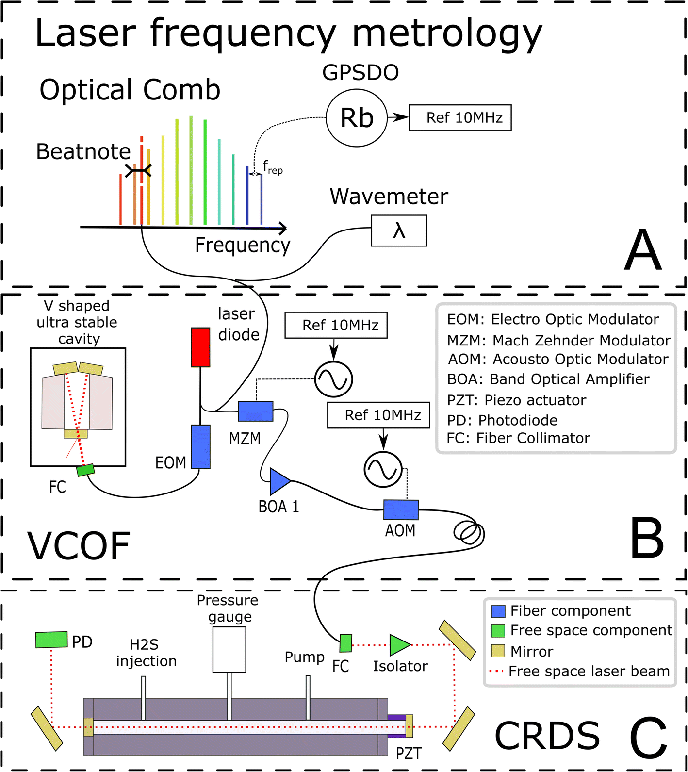 | ||
| Fig. 1 A schematic of the various components of the VCOF-CRDS system. The figure is structured in three blocks, detailing from top to bottom, (A) the frequency calibration, (B) the light source and (C) cavity ring-down spectrometer (CRDS), respectively. GPSDO stands for GPS disciplined oscillator, and VCOF stands for V-shaped cavity-based optical feedback. | ||
Laser frequency metrology
The laser source is a fibered distributed feedback laser, an easily available and widely used telecom technology. However, these lasers are noisy and have rather unstable emission frequency. They have a typical linewidth in the MHz range and frequency drifts of several tens of MHz that would highly limit the accuracy of measurements if not stabilized. With the optical feedback between the cavity and the laser, the emission spectra of the diode can be squeezed, and the stabilization of its central emission frequency can be achieved by transferring the robust optical stability properties of the cavity to the laser itself. In practice, the optical feedback mechanism reduces the laser linewidth well below 1 kHz while keeping its average emission frequency stabilized to better than 10 Hz s−1. The emission frequency of the VCOF source is determined using a wavemeter reading (High Finesse, 30 MHz resolution) refined to the kHz level using a frequency comb (Menlo Systems optical comb in Fig. 1). The VCOF source and comb tooth are mixed on a fast photodiode to record the frequency beat note equal to their optical frequency difference which lies between 0 and 125 MHz. The repetition rate (250 MHz) and carrier offset frequencies (20 MHz) of the comb are locked against a 10 MHz rubidium clock, itself disciplined to the GPS timing signal. This permits an absolute determination of the laser frequency and virtually, unlimited stability of the laser emission frequency. As such, we achieve unmatched precision in the measurements.Optical feedback (OF) mechanism
The OF mechanism occurs when photons from an external cavity excited by a laser come back into the laser gain medium. If the distance from the laser and the cavity is a multiple of half the emission wavelength, the back-propagating photons are in phase with the ones amplified inside the laser cavity. They are therefore efficiently amplified in an avalanche and competitive manner what leads to an emission width well below the VCOF cavity mode width. In the present set-up, the phase is adjusted using an electro-optical phase modulator (EOM) (patent WO 2018/060285A1). This allows robust phase control using a PID controller with a bandwidth of a few tens of kHz. To provide intrinsic long term frequency stability – as desired for a potentially field deployed instrument – the VCOF is designed using thermally stable materials (Invar, ULE glass) and isolated from vibrations by an active optical table26–27 The VCOF permits high stabilization of the laser, but spectroscopy requires an additional tuning scheme. The latter is provided by a Mach–Zehnder Modulator (MZM) used as an optical single-sideband modulator. It permits addition or subtraction of a radio frequency (RF) to the optical frequency in a very agile way.22 The RF is provided by a microwave synthesizer tunable from 2 to 20 GHz. Because the MZM insertion losses are high (10 dB), the frequency shifted laser is further amplified using a Booster Optical Amplifier (BOA) before being injected into the CRDS. An optical isolator protects the BOA and the VCOF against photons that are reflected by the highly reflective mirrors of the CRDS. Tuning the RF permits recording of absorption spectra and dynamic compensation for the slow residual drift of VCOF, which in the lab is monitored at the kHz accuracy level as described above. The stability of the laser is crucial as it sets the reliability of the frequency axis over the measurement periods. The laser frequency must be stable to better than 10 kHz within this period, which is typically 3 seconds, to determine the line area with 10−6 precision.Ring-down mechanism
A stable and tunable laser is injected into the CRDS cell using a single lens and two steering mirrors for a precise mode matching.22–24 The stable CRDS optical cavity is made of a massive aluminium rod (70 mm outer diameter, 8 mm inner diameter, 490 mm length) with two high reflectivity mirrors fitted on its extremities (Layertec GmbH), one being mounted on a PZT actuator (PI) to finely adjust the cavity length to bring its modes in resonance with the probing laser. The cavity finesse F is in excess of 500000 (mirror reflectivity > 0.99999), providing very narrow optical modes and exceptional sensitivity (>5 × 10⁻¹³ cm−1 routine detection limit).22–24 Its free spectral range is 297 MHz and the photon lifetime is close to 300 μs. The mean interaction path between the light and the gas is thus about 90 km. This is significantly higher in comparison to the ≈4.2 km path length in a previous spectroscopic study on H2S.21 The measurements are conducted following the continuous-wave-CRDS scheme.28 In short, the laser is tuned and the cavity is brought into resonance with the laser. Photons that are passing through the mirror are essentially trapped in the cavity, leading to an increase of the intra-cavity power. The transmission of the cavity increases together with the number of photons circulating in the cavity. If the transmission exceeds a given threshold, the laser is interrupted using a fast acousto-optic modulator (AOM). The photons stored in the cavity then flush through the mirrors or vanish because of gas absorption. Both effects result in an exponential decay of the transmission signal (ring-down event), whose time constant (ring-down time) is a reading of the mirror reflectivity and gas absorption contributions. The advantage of this technique is that it is immune to laser intensity fluctuations. Signal-to-noise ratios of up to 106 are reached in the present study by typically averaging 200 ring-down events over one second.
Data acquisition
The reference gas sample used in this study is a mixture of 2000 ppmv H2S in nitrogen at a total pressure of 150 bar (Air Liquide, Crystal 99.8% N2, 2000 ppmv H2S). A regulator valve allows reducing gas pressure to the working pressure of 1 bar before it is injected into the instrument. The filling flow rate is controlled by a proportional solenoid valve (Bürkert Type 2871) with a 0.1 mm aperture. The evacuation rate is controlled using an additional solenoid valve. Pressure in the cavity is measured with a pressure gauge (Baratron AA01, 130 mbar range).Temperature is expected to have a strong influence on the spectra of the sample (10−3 K−1 on the isotopic ratios), because it affects the gas density and the line intensities. We took special care in providing a stable and homogeneous temperature in the CRDS cell. To ensure uniformity the cavity is made of aluminum. This material is a good thermal conductor which makes it possible to limit the temperature gradient. The cavity is as massive as possible to increase thermal time constants. It guarantees very low temperature excursions during the measurement of a spectrum. The cavity is placed in an isolated enclosure regulated by a commercial heat exchanger (Supercool) at 28 °C (±0.05 °C). A PT1000 probe is placed in a 20 mm deep hole drilled in the aluminum to regulate the cavity at 29 °C with a heating wire wound around the cavity and controlled with a home-made PID regulator. Another PT1000, which is symmetrically placed, allows for additional temperature monitoring of the cavity. To limit the reaction of H2S with walls and residual moisture, the tubing and cell have been treated with a protective coating (Silcotek Silconert™ 2000). The pressure regulators, the electro-valves, the CRDS PZT and the pressure gauge are not coated. A few Viton O-rings are in limited contact with the gas in the CRDS cell. The standard pressure inside the CRDS cell is 20 mbar for a volume of 2 × 10⁻⁵ m3 corresponding to 33 nmol of H2S. Each absorption spectrum was acquired by tuning the MZM from 2 to 20 GHz with a step resolution of 50 MHz to determine line parameters, but only a few spectral points are recorded for fast isotopic ratio determination.
The introduction of the gas sample can be done in two different modes. (1) Static: the cavity is repeatedly filled, the gas measured, and then evacuated. (2) Flow: using the pair of electro valves and the pressure gauge readings, a sample gas flow with regulated pressure is set to continuously regenerate the gas sample. Indeed, the reaction of H2S in the CRDS cavity is clearly observed from the time dependence of the partial pressure retrieved from the absorption spectra, especially in static mode. In practice, an upper limit of 5 min per cycle of static measurements is found, after which the isotopic ratios are affected.
Results
S-isotope spectra and fitting regime
Before any potential application it is necessary to correctly characterize the absorption spectrum of the species studied. Therefore, we recorded a series of spectra for the H2S reference gas at increasing total pressures from 17 to 23 mbar (Fig. 2). They were analyzed using the Multi-spectrum Analysis Tool for Spectroscopy (MATS)29 developed at the National Institute of Standards and Technology (NIST). Each line (or group of lines in the case of the 34S doublet) was fit separately with a line profile that aims to reproduce the observed line shape as well as possible for all pressure values. Due to the high signal-to-noise ratio of the spectra, it was necessary to go beyond the Voigt profile – which includes both Doppler (Gaussian) broadening due to the thermal velocity of the molecules, and collisional (Lorentzian) broadening, as well as a collisional shift of the line position – to include more subtle collisional effects such as the Dicke narrowing (collisions modify the velocity distribution) and speed-dependence of the collisional broadening and shifting parameters. We have therefore selected the quadratic speed-dependent Nelkin–Ghatak profile (SDNGP)30 in this work because it includes all these effects. The signal-to-noise ratio was however not sufficient to justify including a correlation between the two narrowing effects as in the Hartmann–Tran profile (HTP).31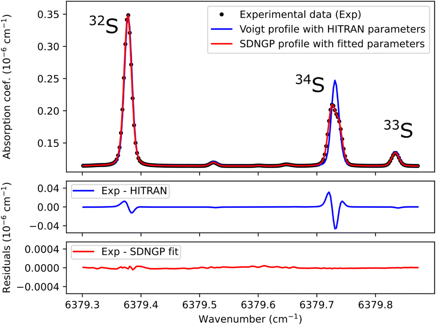 | ||
| Fig. 2 This plot presents a spectrum recorded at a total pressure of 21 mbar (black dots), along with a Voigt profile simulation using HITRAN parameters (in blue) and a fit of the experimental values with the speed-dependent Nelkin–Ghatak profile (SDNGP, in red). The lower two panels show the difference between the experimental spectrum and each calculated curve. Note that the HITRAN positions were shifted by −0.003 cm−1 for the simulation. | ||
The MATS program, written in the Python language, enables simultaneous fitting of several spectra recorded at different pressure conditions, imposing constraints on the pressure dependence of line shape parameters. Here all fit parameters were set to be independent of pressure, except for the line intensities because the H2S concentration in the cell was not accurately known due to degradation in the gas line as mentioned earlier. The line positions were fixed to the values retrieved from Lamb dip measurements as discussed below. The Doppler broadening was fixed to its calculated value. The fit residuals standard deviation is on the order of 10−11 cm−1 for the SDNGP fit and is two orders of magnitude smaller compared to the residuals from the HITRAN simulation (Fig. 2). Table 1 presents the obtained fit parameters for the four major lines in the region of interest.
| Isotope | 32S | 34S1 | 34S2 | 33S |
|---|---|---|---|---|
| Center frequency (ν, cm−1) | 6379.377777(2) | 6379.725458(2) | 6379.738104(3) | 6379.834190(2) |
| Line intensity (S, 10−25 cm−1) | 41.628(2) | 15.38(1) | 8.35(1) | 3.4019(6) |
| Collisional broadening (γ, cm−1 atm−1) | 0.08224(2) | 0.0888(2) | 0.0480(3) | 0.06895(8) |
| Shift (δ, cm−1 atm−1) | −0.009739(8) | −0.0082(3) | −0.0095(4) | −0.01150(3) |
| Rate of velocity-changing collisions (νvc, cm−1 atm−1) | 0.0038(1) | 0.0036(3) | 0.0029(3) | 0.0030(2) |
| Speed-dependence of broadening (aw, dimensionless) | 0.0658(6) | 0.071(2) | 0.128(5) | 0.084(2) |
| Speed-dependence of shift (as, dimensionless) | 0.083(1) | 0.04(2) | −0.08(2) | 0.023(2) |
The uncertainties in the intensities of the lines of the doublet (34S1 and 34S2) are larger by an order of magnitude than those of the other lines. This is due to their overlap, which strongly correlates the two intensities. This translates into a total area of the doublet line that is better known (see fit residuals in Fig. 2) than each of its components. It should be noted that in the case of isotopic analysis based on optical spectroscopy methods, the line intensity does not have to be known with precision. Indeed, by definition of an isotopic ratio,32 the isotopic measurements are relative to spectra realized on standard gases. The spectroscopic model is only there to compensate for the experimental variations (pressure, temperature) between the samples and the standards.
Line position determination by Lamb dip measurement
The studied spectral zone is interesting because it contains the absorption lines of the three isotopologues of H2S but one of these lines is a doublet: it is composed of two lines very close to each other in frequency but coming from different energy levels of the molecule. The HITRAN database contains the two lines with different intensities but attributes the same frequency to them. This approximation explains the difference between the simulated spectra and the experimental/measured spectra (Fig. 3A). To define the frequency of each one of the two lines, the Lamb dip measurement technique can be used (Fig. 3B). Below, we provide more details of the characteristic Lamb dip feature.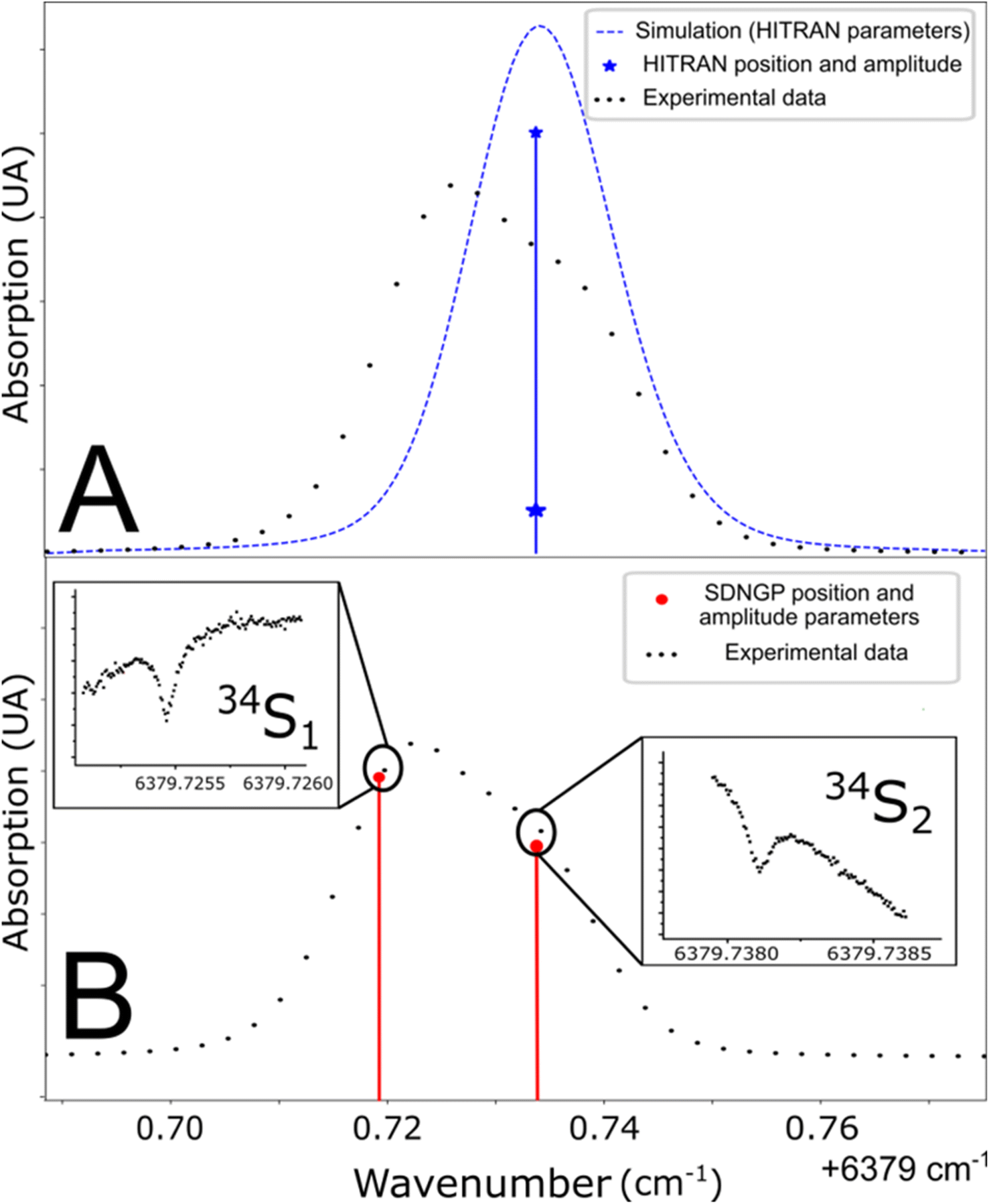 | ||
| Fig. 3 (A) Line position in the HITRAN database and simulation from these parameters (blue line). (B) Determination of doublet frequencies by Lamb dip measurement (red line). | ||
In a molecule, the absorption of a photon of energy (hν) occurs if it corresponds to the difference of two energy levels of the molecule E2 − E1, with E2 > E1. At room temperature, around 1.5 μm, the higher energy level is unpopulated. Even if a photon is absorbed, the higher-level population remains negligible. This is particularly true in the presence of molecular collisions which actively participate in the higher-level depopulation. But at very low pressure and high photon fluxes, this approximation is no more valid, and the absorption seems lowered because of the competition between absorption from the lower state and stimulated emission from the higher state. The transition enters a so-called saturation regime. In an extreme situation the population can be equally shared between lower and higher levels and the medium then appears transparent. The signature of saturation is an optical power dependence of the absorption.
Interestingly, in an optical cavity, photons are traveling back and forth through the gas, which has a temperature related Gaussian velocity distribution of its molecules that is responsible for the Gaussian line shape of the molecular absorption (as in Fig. 2). It is wide by about 600 MHz. Obviously, molecules that have no velocity component along the cavity axis absorb resonant photons traveling on both sides. In contrast, molecules moving along the axis encounter two different frequencies because of the Doppler effect due to their movement. They can only absorb photons traveling from a single direction. In the presence of saturation, molecules with no velocity along the axis are therefore twice as saturated as the others. This manifests as a narrow absorption dip in the exact middle of the absorption line, whose width is essentially due to the time of flight through the cavity mode beam, residual collisions, and power broadening effect. This regime can be achieved in the VCOF-CRDS system at low pressure, and for strong absorption, thanks to the five orders of magnitude power enhancement brought by the high finesse resonant cavity.
Fig. 3 shows spectra recorded in such a regime, at a pressure of 0.1 mbar. The laser frequency was roughly stepped (50 MHz step) to reveal the broad Gaussian shape of the line and then finely stepped (50 kHz) close to the center of the absorption line. The Lamb dip feature is well marked. It indicates the zero-pressure position of the line with high precision and accuracy. This is the first report of the Lamb dip feature for S-isotope spectra of H2S. We repeated the measurement for the three isotopologues to determine every absorption frequency. It is worth noting that this permits unambiguous determination of individual positions for the blended H234S doublet (as seen in Fig. 3). The obtained positions were used to constrain the multi-pressure fit (Table 1). We insist that no saturation effect was observed above 1 mbar.
Estimation of measurement precision
The high-resolution spectra recorded to conduct the pressure dependent fit have a necessarily limited accuracy and precision. To be properly determined, the uncertainties of the fitted parameters must consider the fluctuations of the external physical parameters and their own uncertainties. Following BIPM recommendations for such an approach,32 we proceed as follows: let us consider the measured absorption spectrum to be a function Y which depends on four different parameters, namely the temperature T, the pressure P, the frequency f and the absorption of the gas α. This set of parameters forms the vector B. If the function Y produced by the spectroscopic model is realistic – i.e., leading to essentially flat and limited residuals – the Jacobian vector J and the covariance matrix permit a reliable evaluation of the uncertainties. The Jacobian vector reads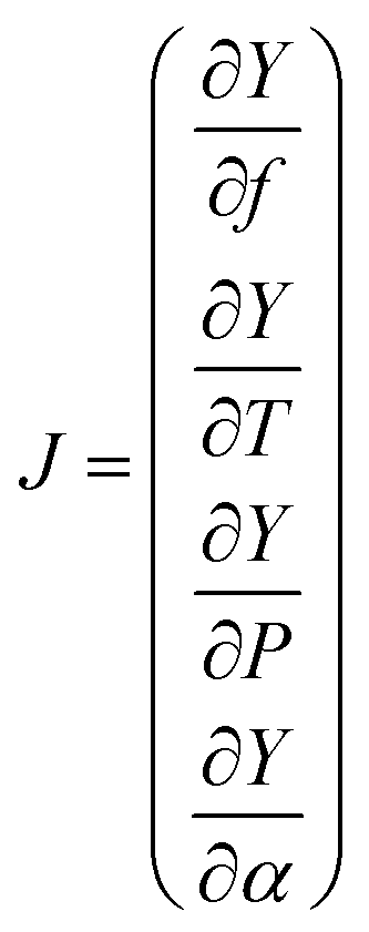 | (1) |
The covariance matrix cov(B) can then be written as follows and simplified by setting uncorrelated parameters to 0:
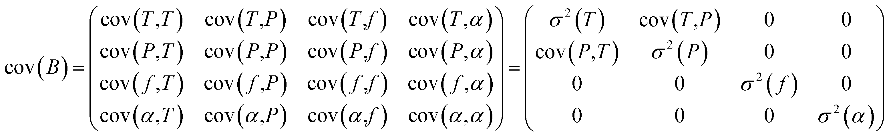 | (2) |
Finally, the uncertainty σ2 (Y(ν)) reads:
| σ2(Y(ν)) = cov(Y(ν),Y(ν)) = Jcov(B)Jt | (3) |
From this experimental uncertainty we can estimate the uncertainty in isotopic ratio measurements. This theoretical experimental uncertainty is compared to the statistics carried out on a corpus of 1000 spectra. A good agreement is observed between the calculated σ2 value and the thickness of the trace of isotopic ratios, but this study highlights a drift in measurements. Measurement strategies need to be put in place to correct these drifts. The standard solution is the alternative use of sample and standard injections using a gas management system.
Discussion
The spectroscopic investigation of H2S isotopologues in the near-infrared region was conducted from a high- to low-pressure regime (21 mbar and 0.1 mbar) with the so-called VCOF-CRDS setup. Spectroscopic parameters of H2S absorption lines and their pressure dependence were assessed with a multi-pressure fit and their uncertainties were determined. A drift was evidenced in the measurement of isotope ratios (Fig. 4). Plausible explanations for this drift are as follows: (a) an issue with the temperature/pressure sensor that affects the gas absorption lines, (b) a thermo-mechanical stress that affects the optical alignment, which slowly distorts the baseline, (c) spectral interference by outgassing molecules like the above-mentioned CO2 lines overlapping with the 34S line, as shown in Fig. 5. Monitoring the isolated strong line of CO2 permitted explicit addition of CO2 contribution in the spectroscopic fitting model. Interestingly, water vapor was never detected over the entire experiment period even though it is known to continuously outgas even with a dedicated cell coating. We suspect it is chemically destroyed by reaction with H2S, what may partly also explain the short lifetime of H2S in the cell. We estimate that the isotopic ratio drift is most likely due to the spectral interference from other gas molecules. Further investigations are planned to better understand the pattern of the drift.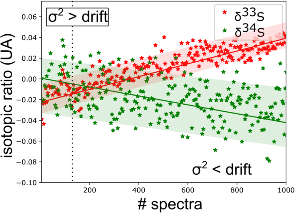 | ||
| Fig. 4 Time series of isotopic ratio measurements (3 s per spectra) reveal a spectral interference between H2S and other outgassed molecules [CO2 lines are observed in ‘old’ gas (Fig. 5)]. This sets a limit to the experimental repeatability. | ||
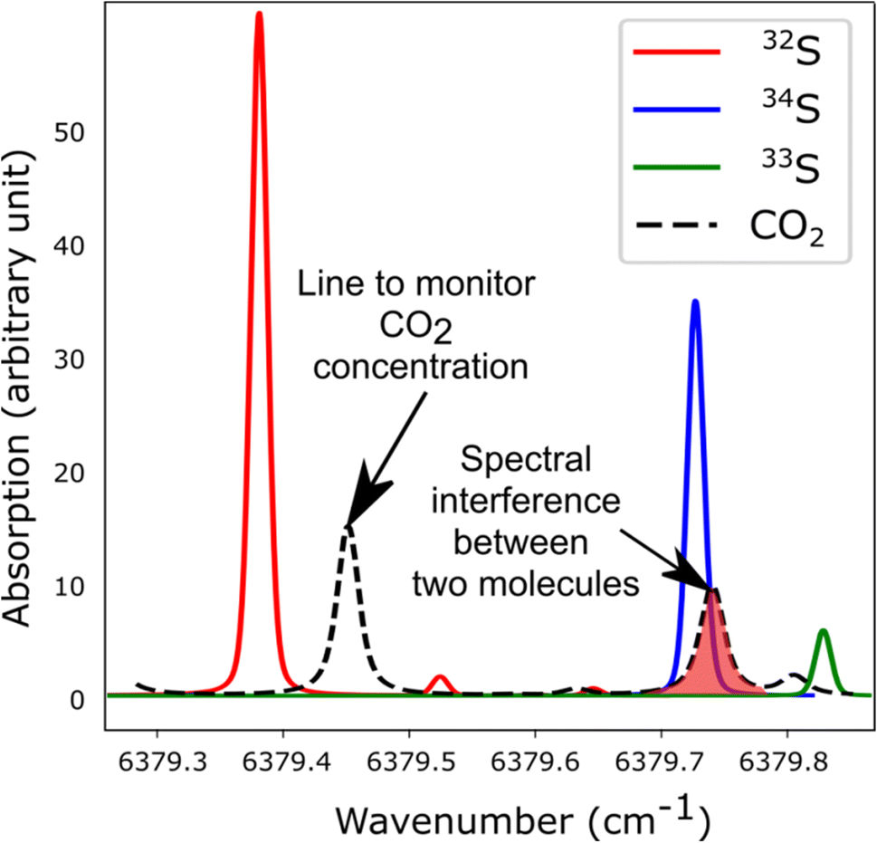 | ||
| Fig. 5 Simulated spectra showing the S-isotopologue lines of H2S and interfering CO2 lines in the spectral region covered by the VCOF-CRDS setup. | ||
We conclude that a precision (repeatability) of 5 ppm can be achieved for up to 10 spectral measurements within less than 1 minute. This high precision makes it possible to perform isotopic ratio measurements on H2S for real world applications. However, to understand the accuracy (reproducibility) of the system a simultaneous injection of the ‘sample’ and ‘standard’ of known isotopic composition is needed. This can be achieved with an efficient gas management system i.e., a dual-inlet system, which is under construction. This aspect will be explored as part of future study with the VCOF-CRDS setup. Moreover, we are planning to investigate the less abundant H236S isotope spectrum, whose spectrum is unknown in this region.
Summing up, the VCOF-CRDS system opens new frontiers in laser spectroscopy-based isotope measurements of H2S. The robustness of the system in terms of the ultrahigh sensitive laser linewidth (a few kHz) coupled to a huge optical pathlength allows for high-precision measurements. The detection of the Lamb dip features of the triple S-isotopes confirms the laser quality and instrumental sensitivity and permitted high refinement of H2S line positions. The spectral fitting approach developed in this study can be extended to further investigations of H2S in the near IR region and the present line parameters of 34S, 33S and 32S lines complement the HITRAN database, which is very sparse in this region. This analytical instrument paves the way for a wide range of applications in the fields of sulfur isotope geochemistry, biomedical applications and environmental sensing.
Author contributions
S. K., J. S., M. D. and J. C. built the instrument; J. C., S. K. and S. D. conducted the measurements; H. F. and J. C. performed the pressure-dependent spectral fit; S. D., J. C. and S. K. drafted the paper and wrote the paper with input from all co-authors.Conflicts of interest
The authors declare no competing financial interests.Acknowledgements
S. D. and J. S. acknowledge support from the Marie Skłodowska-Curie Action grant number 1010180 (to S. D.; hosted by J. S.). S. K. and J. S. acknowledge financial support from the French National program LEFE (Les Enveloppes Fluides et l'Environnement), the MITI initiative “Défi Isotope” of the CNRS and the LabEx OSUG@2020 (“Investissements d'avenir” – ANR10 LABX56).References
- H. G. Thode, Sulfur isotopes in nature and the environment: an overview, Wiley, England, 1991, vol. 43, pp. 1–26 Search PubMed.
- B. B. Jørgensen, A. J. Findlay and A. Pellerin, Front. Microbiol., 2019, 10, 849 CrossRef.
- J. H. Seinfeld and S. N. Pandis, Atmos. Chem. Phys.: From Air Pollution to Climate Change, John Wiley & Sons, Inc., New York, 1996 Search PubMed.
- S. Solomon et al . , Climate Change 2007: The Physical Science Basis, Contribution of the Working Group I to the Fourth Assessment Report of the Intergovernmental Panel on Climate Change, Cambridge University Press, New York, 2007 Search PubMed.
- M. Kulmala and et al, . , Science, 2007, 318, 89–92 CrossRef CAS.
- W. Li, X. Liang, X. Liu, J. Zhang, Y. Lin, X. Yao, H. Gao, D. Zhang, J. Chen, W. Wang and R. M. Harrison, Sci. Adv., 2017, 3, e1601749 CrossRef PubMed.
- S. Mertes, D. Galgon, K. Schwirn, A. Nowak, K. Lehmann, A. Massling, A. Wiedensohler and W. Wieprecht, Atmos. Environ., 2005, 39, 4233–4245 CrossRef CAS.
- P. Arias, et al., Climate Change 2021: The Physical Science Basis. Contribution of Working Group I to the Sixth Assessment Report of the Intergovernmental Panel on Climate Change, Cambridge University Press, New York, 2021 Search PubMed.
- J. O. Nriagu, R. D. Coker and L. A. Barrie, Nature, 1991, 349, 142–145 CrossRef CAS.
- Y. Shen, R. Buick and D. E. Canfield, Nature, 2001, 410, 77–81 CrossRef CAS PubMed.
- J. Farquhar, H. Bao and M. Thiemens, Science, 2000, 289, 756–759 CrossRef CAS.
- D. Yang, P. Cartigny, K. Desboeufs and D. Widory, Atmos. Chem. Phys., 2019, 19, 3779–3796 CrossRef CAS.
- G. Paris, A. L. Sessions, A. V. Subhas and J. F. Adkins, Chem. Geol., 2013, 345, 50–61 CrossRef CAS.
- J. Morville, D. Romanini and E. Kerstel, Cavity enhanced absorption spectroscopy with optical feedback, in Cavity-Enhanced Spectroscopy and Sensing, ed. G. Gagliardi and H.-P. Loock, Springer, Berlin Heidelberg, 2014, pp. 163–209 Search PubMed.
- G. D. Banik, A. De, S. Som, S. Jana, S. B. Daschakraborty, S. Chaudhuri and M. Pradhan, J. Breath Res., 2016, 10, 026010 CrossRef.
- H. Moser, W. Pölz, J. P. Waclawek, J. Ofner and B. Lendl, Anal. Bioanal. Chem., 2017, 409, 729–739 CrossRef CAS PubMed.
- M. Nikodem, K. Krzempek, D. Stachowiak and G. Wysocki, Opt. Eng., 2017, 57, 011019 Search PubMed.
- M. S. De Cumis, S. Viciani, S. Borri, P. Patimisco, A. Sampaolo, G. Scamarcio, P. De Natale, F. D'Amato and V. Spagnolo, Opt. Express, 2014, 22, 28222 CrossRef PubMed.
- M. Helman, H. Moser, A. Dudkowiak and B. Lendl, Appl. Phys. B, 2017, 123, 1–8 CrossRef CAS.
- H. Moser, A. Genner, J. Ofner, C. Schwarzer, G. Strasser and B. Lendl, Opt. Express, 2016, 24, 6572 CrossRef CAS PubMed.
- M. Pal, M. S. Maithani, A. Maity and M. Pradhan, J. Anal. At. Spectrom., 2019, 34, 860–866 RSC.
- J. Burkart, D. Romanini and S. Kassi, Opt. Lett., 2013, 38, 2062–2064 CrossRef PubMed.
- J. Burkart, D. Romanini and S. Kassi, Opt. Lett., 2014, 39, 4695–4698 CrossRef PubMed.
- T. Stoltmann, M. Casado, M. Daeron, A. Landais and S. Kassi, Anal. Chem., 2013, 89, 10129–10132 CrossRef.
- I. E. Gordon and et al, . , J. Quant. Spectrosc. Radiat. Transfer, 2022, 277, 10794 CrossRef.
- M. Casado, T. Stoltmann, A. Landais, N. Jobert, M. Daëron, F. Prié and S. Kassi, Appl. Phys. B: Lasers Opt., 2022, 128, 1–7 CrossRef.
- N. Jobert, M. Casado and S. Kassi, Appl. Phys. B: Lasers Opt., 2022, 128, 1–7 CrossRef.
- D. Romanini, P. Dupré and R. Jost, Vib. Spectrosc., 1999, 19, 93–106 CrossRef CAS.
- E. M. Adkins. Multi-Spectrum Analysis Tool for Spectroscopy, 2020, DOI:10.18434/M32200.
- H. Tran, N. H. Ngo and J. M. Hartmann, J. Quant. Spectrosc. Radiat. Transfer, 2013, 129, 199–203 CrossRef CAS.
- N. H. Ngo, D. Lisak, H. Tran and J. M. Hartmann, J. Quant. Spectrosc. Radiat. Transfer, 2013, 129, 89–100 CrossRef CAS.
- Joint Committee for Guides in Metrology, Guide to the Expression of Uncertainty in Measurement, Paris, 2008 Search PubMed.
| This journal is © The Royal Society of Chemistry 2023 |