
Hierarchically porous Ni foam-supported Co and Sn doped Ni3S2 nanosheets for oxygen evolution reaction electrocatalysts†
Won Young
An‡
a,
Hyungwoo
Lee‡
b,
Sung Ryul
Choi
a,
Sungyong
Choi
a,
Hyun-Seok
Cho
 c,
Minseok
Choi
b and
Jun-Young
Park
*a
c,
Minseok
Choi
b and
Jun-Young
Park
*a
aHMC, Department of Nanotechnology and Advanced Materials Engineering, Sejong University, Seoul 05006, Korea. E-mail: jyoung@sejong.ac.kr; Tel: +82 2 3408 3848
bDepartment of Physics, Inha University, Incheon 22212, Korea. E-mail: minseokchoi.phd@gmail.com
cPolymer Electrolyte Fuel Cell Research Center, Hydrogen and Fuel Cell Department, Korea Institute of Energy Research (KIER), Daejeon 34129, Korea
First published on 22nd February 2023
Abstract
To enter the era of a clean and sustainable hydrogen economy, it is crucial to first discover non-noble metal electrocatalysts that can be used for oxygen evolution reactions (OER) of water electrolyzers. Herein, we demonstrate highly active and durable Co- and Sn-co-doped Ni3S2 catalysts supported on Ni foam (CoSn-Ni3S2@NF) for the OER in alkaline media. Benefiting from the hierarchically porous nanosheet morphology and synergistic strong electron interaction among Co, Sn, and Ni ions, the CoSn-Ni3S2@NF achieves outstanding OER activity in 1 M KOH with a low overpotential of 321 mV at a current density of 0.2 A cm−2. Furthermore, the CoSn-Ni3S2@NF alkaline water electrolysis cell shows a significantly high current density of 1.367 A cm−2 at a cell voltage of 2.0 V under 80 °C and 30 wt% KOH condition using a nickel–iron layered double hydroxide for the hydrogen evolution reaction and a Zirfon PERL separator (500 μm). Based on the defect formation energy and electronic structure obtained using density functional theory calculation, the enhanced intrinsic activity of CoSn-Ni3S2@NF can be attributed to the Co and Sn dopants with S vacancies, which increase activation sites (and free electrons) and favorably modify the Ni 3d-band center to be closer to the Fermi level. This work not only demonstrates a highly electrocatalytic active OER catalyst for water electrolyzers, but also provides a new design principle that can be used for high performance materials by tailoring the electronic structure of transition and post transition metal ions.
Introduction
Due to the global phenomena of climate change, environmental pollution, and energy crises, eco-friendly hydrogen is attracting substantial attention as a next-generation sustainable energy carrier.1,2 Hydrogen gas has numerous applications in metallurgy, petrochemical refinery, processing foods, and automobiles, and it is advantageous in various ways, including its high energy density (120–140 MJ kg−1), the fact that it is the most abundant element, and its environmental friendliness.3,4 Currently, natural gas reforming methods based on fossil fuels using high-temperature steam account for the majority of hydrogen production.5 While gas reforming methods are the cheapest and most common methods, they cause major threats to the environment and natural resources due to greenhouse gas emissions. More recently, water electrolysis-based hydrogen generation has provided a beneficial opportunity to produce hydrogen gas renewably without affecting nature and natural resources.6 Among these, alkaline water electrolysis (AWE) is the most industrially mature technology for hydrogen generation that uses an applied electricity.7 When the direct current is applied to the AWE cells, water is dissociated at the cathode to form H2 through hydrogen evolution reactions (HERs), thus releasing hydroxide anions (OH−) in alkaline solution (e.g., potassium hydroxide). The OH− formed in this way crosses through the membrane separator and then reacts to form O2 at the anode by the oxygen evolution reactions (OERs). The OER is the rate-determining step of AWE cells due to the sluggish kinetics with high overpotential, leading to reduced energy efficiency of AWE cells.8–10 In addition, the use of noble metal OER electrocatalysts such as IrO2 and RuO2 restricts the large-scale commercialization of AWE cells.11Very recently, transition metal chalcogenides (TMCs) based on group 16 elements such as sulfide, selenide, and telluride have attracted substantial attention as OER catalysts due to their excellent catalytic activity, low price, and good corrosion resistance in the alkaline electrolyte.12,13 Among chalcogenide materials, comprehensive electrochemical analyses coupled with theoretical density functional theory (DFT) calculations have demonstrated that heazlewoodite phase nickel sulfides (Ni3S2) represent one of the best candidates for OER catalysts because of their excellent catalytic activity, high electronic conductivity, and good stability in alkaline solutions, as they benefit from the property of covalency between Ni and S and the 3d orbital electronic structures of Ni.14–16 In particular, hydrothermally synthesized Ni3S2 nanostructured catalysts have exhibited similar performance to noble RuO2 catalysts, with a low overpotential of 187 mV at 10 mA cm−2 in 0.1 M KOH.17 However, a facile and reproducible manufacturing process for hierarchically porous nanostructured Ni3S2 should be established, since nanostructured catalysts have exhibited considerable variations in OER electrochemical performances, even within the same catalyst.18 Further, there is great potential in enhancing the OER performance of Ni3S2 catalysts through an atomic surface modification strategy with specific elements.19,20
An atomic surface modification with specific elements is an effective method to further boost the OER property by manipulating the electronic structure and charge transport kinetics of electrocatalysts.21,22 Song et al.23 reported Co-doped Ni3S2 hierarchical nanoarrays on NF substrate (Co-Ni3S2@NF) derived from zeolitic imidazolate frameworks with a trunk-branch three-dimensional composite structure. The Co-Ni3S2@NF showed a low overpotential of 120 mV at 10 mA cm−2 (1 M KOH) for the OER and long-term electrochemical durability in alkaline conditions. Yu et al.24 reported that the introduction of Sn element had a significant effect on the structure and morphology of Ni3S2 nanosheet arrays on Ni foam via a simple solvothermal synthesis method. The Sn-Ni3S2@NF exhibited efficient and durable electrocatalytic hydrogen evolution reaction (HER) activity both in acid and alkaline conditions, by providing more exposed active edges and a shorter electron transfer path. Jian et al.25 also demonstrated that Ni3S2 nanosheet doped with Sn grown on NF (Sn-Ni3S2@NF) through a hydrothermal procedure had a large current density and high stability for both the HER and the OER. In another study, Cao et al.26 synthesized highly active and durable Fe-doped Ni3S2 electrocatalysts in the form of vertically oriented nanosheets deposited on three-dimensional Ni foam (Fe-Ni3S2@NF) for the OER in alkaline media. The introduction of the Fe ions significantly improved the OER activity of Ni3S2 catalysts (1.54 V at 10 mA cm−2 in 1 M KOH) by increasing the electrochemical surface area and the water adsorption ability with the formation of Ni–Fe (oxy)hydroxide. That is, Ni3S2 materials can be used through doping of transition metal and post-transition metal ions (e.g., Fe, Co, and Sn) to efficiently modify the surface electron distribution of catalysts and tune the surface adsorption of key active intermediates for the OER, which substantially accelerates the charge transfer kinetics and maximizes the utilization of active sites of catalysts.27–29
However, many studies to this point have focused on performance (overpotential or stability) at low current densities of 10 mA cm−2, which is unsatisfactory for practical applications.30,31 To secure commercially appropriate hydrogen production capacity, the typical operational current density of a water electrolyzer is preferably above 0.2 A cm−2 with a voltage between 1.7 and 2.4 V.32 In addition, along with the measured electrochemical OER performances, the results of theoretical DFT calculations. Such as the analysis of the electronic structures of Ni3S2 under the doping of transition metal ions, have not been systemically investigated and summarized in mechanistic studies. In particular, although there have been studies on the effect and mechanism of transition metal doping in Ni3S2-based catalysts to further boost OER catalyst performances,33,34 there have been very few mechanistic studies related to the doping of post-transition metals or co-doping with transition metals.
Herein, further OER improvements to the Ni3S2 catalyst are achieved to take advantage of the feasible benefits of the synergistic structures through co-doping of the multi-valent transition metal (e.g., Co2+/3+ and Fe2+/3+) and post-transition metal ions (e.g., Sn4+) into the Ni-site. We also investigate an undemanding, scalable, and reproducible synthesis process for hierarchically porous Ni3S2-based materials on nickel foam (Ni3S2@NF), thus enabling the design of highly active, durable, and cost-effective catalysts in alkaline solutions. Moreover, this result is verified by examining the electronic configuration and oxidation state of co-doped Ni3S2 catalysts critical to their activity and stability for the OERs using theoretical DFT calculations. This work demonstrates new perspectives in developing highly electrocatalytic active OER catalysts for AWE cells with potential applications in the future.
Experimental
Synthesis of transition and post transition metal doped-nickel sulfide on Ni foam
Hierarchically porous nickel foam-supported Ni3S2 (Ni3S2@NF) was synthesized via a simple and scalable hydrothermal synthesis method. To prepare Ni3S2@NF electrocatalysts, 0.6 mmol thiourea (CH4N2S, Alfa Aesar, 99%) was mixed in a solution containing 40 mL of de-ionized (DI) water and stirred for 30 min. Before performing the hydrothermal reaction, the nickel foam (NF, 1 × 3 cm2 in size) was sonicated in 3 M hydrochloric acid (Samchun, 35.0–37.0%) for 30 min, then cleaned with acetone, ethanol, and de-ionized water for 10 min to remove surface impurities. Next, the Ni3S2@NF electrocatalysts were synthesized hydrothermally at 160 °C for 4 h in a stainless-steel autoclave (Ilshin Autoclave, 80 mL Teflon-lined beaker).The transition (e.g., Co, Fe, and Ni) and post transition metal (e.g., Sn)-doped Ni3S2@NF (Co-, CoSn-, CoFe-, and CoNi-Ni3S2@NF) catalysts were also prepared via a one-step hydrothermal synthesis method in the same manner as described above for Ni3S2@NF. To synthesize Co-Ni3S2@NF catalysts, 0.3 mmol Co chloride (CoCl2·6H2O, Sigma-Aldrich, 98%) precursor and 0.6 mmol thiourea were mixed in a solution containing 40 mL of de-ionized water for 10 min. In the case of CoSn-, CoFe-, and CoNi-doped Ni3S2@NF, 0.25 mmol Co chloride, 0.6 mmol thiourea, and 0.05 mmol Sn chloride (SnCl2·2H2O, Alfa Aesar, 98.0–103.0%), Fe chloride (Cl2Fe, Alfa Aesar, 99.5%), and Ni chloride (Cl2Ni, Alfa Aesar, 98%) were mixed in de-ionized water, respectively. Subsequently, the materials were hydrothermally synthesized at several different temperatures (120, 140, and 160 °C) and times (1, 4, and 7 h) in an autoclave.
Characterization of pristine and metal doped-Ni3S2@NF catalysts
The crystal structures were analyzed using the X-ray diffraction (XRD) technique (Pan Analytical, X'Pert Diffractometer) with filtered Cu-Kα radiation source (λ = 1.5406 Å wavelength). The XRD patterns were evaluated through step scanning in the 2θ range of 20–80° with intervals of 0.02°. To characterize the morphologies and crystalline properties of the catalysts, field emission scanning electron microscopy (FE-SEM, S-4700 Hitachi, acceleration voltage of 15 kV) and high-resolution transmission electron microscopy (HR-TEM, JEM-F200, JEOL, acceleration voltage of 200 kV) were conducted with the corresponding energy-dispersive X-ray spectroscopy (EDX) elemental mapping images of the component phases.The chemical bonding states and electronic structures of the pristine and doped-Ni3S2@NF catalysts were determined by X-ray photoelectron spectroscopy (XPS, VG Escalab 200i, UK) with an Al Kα X-ray source (hν = 1486.6 eV). The relative atomic concentrations of Ni 2p, Co 2p, Sn 3d, and S 2p were compared using the peak intensities and integrated area ratios of the catalysts. The surface area (Brunauer–Emmet–Teller, BET) of the pristine and doped-Ni3S2@NF catalysts was analyzed with a BELSORP-max, BEL instrument while using the N2 adsorption/desorption isotherms at 77 K. Before the measurements, all of the samples were pre-treated at 80 °C for 3 h. The total pore volume was investigated by converting the adsorbed N2 gas amount at a relative pressure (P/P0) of 0.99 to the liquid volume of N2 adsorbate. The Barrett–Joyner–Halenda (BJH) method was used to calculate the pore size distributions in the micropore range from the adsorption branches of the isotherms. The inductively coupled plasma optical emission spectrometry (ICP-OES) experiments were performed with equipment from Spectro (Spectro Arcos II ICP-OES) to analyze the elemental content of catalysts.
Electrochemical measurements of doped-Ni3S2@NF catalysts
Electrochemical measurements of the electrocatalysts were carried out using a potentiostat/galvanostat VSP (Biologics, France) with a standard three-electrode system, which uses a Ni3S2@NF-based catalyst as a working electrode (electrode area = 1 × 0.1 cm2), Pt wire as a counter electrode, and Hg/HgO saturated 1 M NaOH as a reference electrode at room temperature. For the electrochemical measurements, the reversible hydrogen electrode (RHE) scale was used to convert all of the potentials. Prior to electrochemical testing, cyclic voltammetry (CV) scans were performed from 0.05 to 1.2 V for 50 cycles (scan rate of 100 mV s−1) in 1 M KOH to clean the surfaces of Ni3S2@NF-based catalysts and stabilize the current. Oxygen evolution reaction (OER) activity measurements were achieved using CV in O2-saturated 1 M KOH electrolyte solution at a scan rate of 5 mV s−1 between 1.2 and 1.7 V. The overpotentials (η) were ascertained at current densities of 0.1 and 0.2 A cm−2. Hydrogen evolution reaction (HER) activity was measured in O2-saturated 1 M KOH solution using the linear sweep voltammetry (LSV) method from −0.6 to 0 V at a scan rate of 5 mV s−1.Electrochemical impedance spectroscopy (EIS) measurements (SP240, BioLogic Science Instruments) were conducted in the range between 100 mHz and 100 kHz at an applied potential of 1.6 V (amplitude at 10 mV). The resistance factors were divided into charge-transport resistance (Rct) and mass-transport resistance (Rmt) from the fitted equivalent circuit model using EC-Lab software. The electrochemical active surface area (ECSA) of the catalysts was investigated by dividing the double-layer capacitances (Cdl) by the specific capacitance. ECSAs were calculated under different scan rates of 10, 20, 40, 60, and 80 mV s−1 from 0.05 to 0.25 V. Durability tests were conducted using chronopotentiometry experiments under a constant current density of 0.2 A cm−2 for 10 and 97 h in O2-saturated 1 M KOH solution for the OER.
The electrolysis experiments were conducted with a single cell zero-gap configuration composed of Ni porous transport layers and bipolar plates (single serpentine flow field). The Zirfon Perl membrane (Agfa, thickness of 500 μm, for 30 wt% KOH solution) and alkaline exchange membrane (AEM, Fumasep FAA-3-50, for 1 M KOH solution) were used as separators for the electrolysis tests. The nickel–iron layered double hydroxide electrode on the nickel foam (NiFe-LDH@NF) and prepared doped-Ni3S2@NF were used as anodic catalysts for the HER and the OER, respectively. The electrode area of the alkaline water electrolysis (AWE) cells was 1.65 × 1.65 cm2. The AWE cells were operated at 55 and 80 °C and 30 wt%, and 1 M KOH electrolyte solutions were circulated to the cell electrode at a flow rate of 200–300 ccm. I–V polarization curves were measured by a potentiostat (Advanced Power system N7970A, Agilent Technologies) as a function of the current density. EIS analysis was performed in the range between 10 mHz and 100 kHz under the applied current densities of 0.125, 0.5, and 1 A cm−2.
Density functional theory calculation
To address the roles played by Co and Sn doping in catalytic performance, density functional theory (DFT) calculations were made using the projector augmented-wave method and the exchange-correlation functional constructed by the generalized-gradient-approximation in the Perdew–Burke–Ernzerhof scheme,35 as implemented in the VASP code.36 A rotationally invariant Hubbard + U method37 was applied to Ni 3d (Ueff = 6.2 eV) and Co 3d (Ueff = 4.4 eV) states. The electronic wave functions were described using a plane wave basis set with an energy cut off of 500 eV. All cell parameters were optimized with a residual force cut off of 0.02 eV Å−1. A five-atom unit cell and a 10 × 10 × 10 k-point grid for the Brillouin zone integration were used for pristine Ni3S2. To investigate the use of metal dopants (i.e., Co and Sn) and its correlation with native defect, several point defects, Ni vacancy (VNi) and S vacancy (VS), were considered. To simulate the metal-doped and defective Ni3S2, 135 atom supercells and 3 × 3 × 3 k-point were employed.The defect formation energies (Ef) of the defects with/without metal dopants were evaluated using the following equation:38
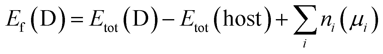 | (1) |
 . Here ΔHf(Ni3S2) is the formation enthalpy of Ni3S2. The d-band center is known to be a promising descriptor for understanding catalytic activities, so the metal d-band center (εd) is examined using the following equation:
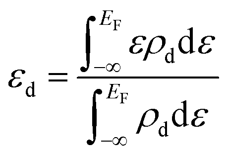 | (2) |
Result and discussion
Physicochemical characterizations of doped nickel sulfides catalysts
Hierarchically structured porous pristine (Ni3S2@NF), Co (Co-Ni3S2@NF), CoSn (CoSn-Ni3S2@NF), CoFe (CoFe-Ni3S2@NF), and CoNi-doped nickel sulfides (CoNi-Ni3S2@NF) catalysts on nickel foam (NF) substrate were synthesized using a facile one-step hydrothermal method. To realize high OER performance through the synthesis of hierarchically porous nanostructured catalysts, pristine and doped Ni3S2 were synthesized under various process conditions [synthesis temperatures (120, 140, and 160 °C) and holding times (1, 4, and 7 h)]. The crystal structures and phase purities of the Ni3S2@NF and doped-Ni3S2@NF synthesized at 160 °C for 4 h were characterized through X-ray diffraction (XRD) patterns. As displayed in Fig. 1a, aside from the three main peaks indexed to nickel foam, the five main diffraction peaks of pristine (Ni3S2@NF) and Co-doped nickel sulfides at 21.8°, 31.1°, 37.8°, 50.1°, and 55.2° were commensurate with those of the heazlewoodite phase of Ni3S2 (JCPDS no. 44-1418).39 Moreover, the enlarged portion of 2θ (in 30° to 33°) evidently indicates the effect of doping as the diffraction peaks shift toward higher (lower) 2θ, due to the smaller (larger) ionic radii of Co, Fe, and Sn ions, which are doped at host element Ni2+ site in the four-coordination number, respectively.40 An additional impurity peak of Co3Ni6S8 in Co-Ni3S2@NF was found at 28° (Fig. S1†), which might be attributable to the side reactions of NF and thiourea (CH4N2S) with CoCl2 during the hydrothermal synthesis.41 However, in cases of the doping of Sn and Fe for Co-Ni3S2@NF catalysts (synthesized at 160 °C for 4 h), a complete heazlewoodite phase was successfully formed with no specific impurities, as shown in Fig. 1a. Meanwhile, Fig. 1b shows the crystal structure of CoSn-Ni3S2@NF. Heazlewoodite structure Ni3S2 was described as a rhombohedral structure, and Ni was occupied by a tetrahedral site, which corresponds to the unit cell of a = 4.01 Å and a space group of R32 (155).42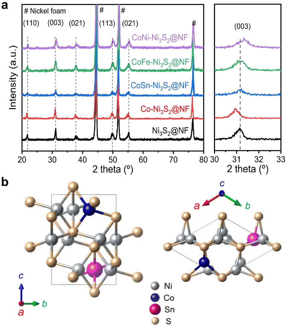 | ||
| Fig. 1 Structural and phase analyses of pristine and doped-Ni3S2@NF catalysts using XRD. (a) XRD patterns of Ni3S2@NF and T-Ni3S2@NF (T = Co, CoSn, CoFe, and CoNi) catalysts. (b) Heazlewoodite structure of CoSn-Ni3S2 phase with a space group of R32 (155). | ||
The size and morphology of the pristine and doped-Ni3S2@NF electrocatalysts were investigated by field emission scanning electron microscopy (FE-SEM, Fig. 2). Fig. S2† shows that the hydrothermal synthesis conditions (temperature and holding time) substantially affected the microstructure of the Co-Ni3S2@NF electrocatalysts. It was found that Co-Ni3S2@NF synthesized using the hydrothermal method at 160 °C for 4 h exhibited the most optimized morphology of hierarchically porous and ultrathin nanosheets. Accordingly, CoSn-Ni3S2@NF, CoFe-Ni3S2@NF, and CoNi-Ni3S2@NF catalysts were prepared by the same hydrothermal reaction condition at 160 °C and 4 h. For the CoSn-, CoFe-, and CoNi-Ni3S2@NF catalysts, randomly interconnected and highly porous nickel sulfides flakes are vertically grown on the NF substrate, as shown in Fig. 2.
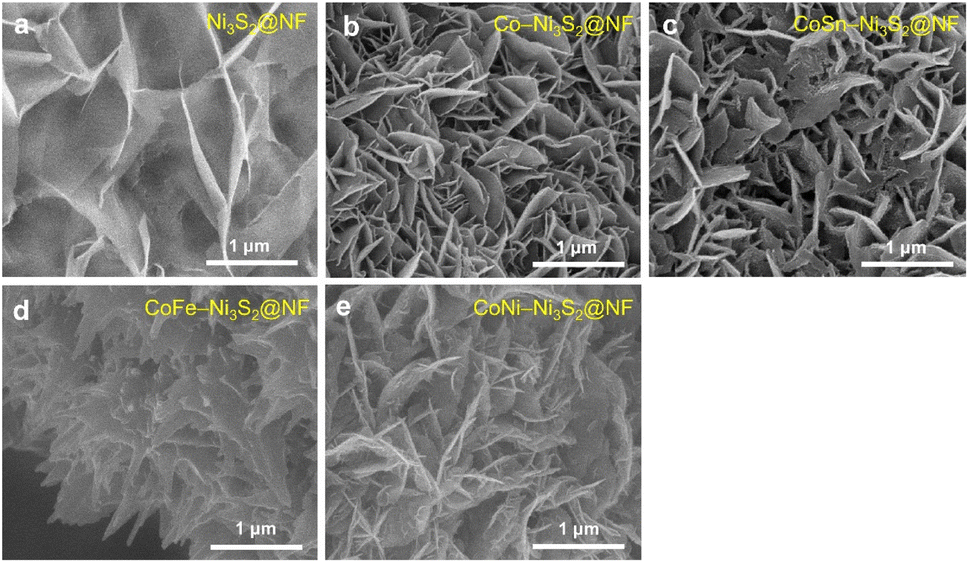 | ||
| Fig. 2 FE-SEM image of pristine and doped-Ni3S2@NF catalysts. (a) Ni3S2@NF, (b) Co-Ni3S2@NF, (c) CoSn-Ni3S2@NF, (d) CoFe-Ni3S2@NF, and (e) CoNi-Ni3S2@NF. | ||
Fig. 3a and b (Fig. S3a†) shows high resolution-transmission electron microscopy (HR-TEM) images for the and CoSn-Ni3S2@NF (Ni3S2@NF and Co-Ni3S2@NF) arrays. The calculated interplanar d-spacing of CoSn-Ni3S2@NF (Ni3S2@NF and Co-Ni3S2@NF) is about 0.287 nm (0.286 and 0.288 nm, respectively), which is assigned to the (110) crystal plane of Ni3S2, in accordance with the XRD results (JCPDS no. 44-1418).43 In the selected area electron diffraction (SAED) pattern analyzed at the [1![[1 with combining macron]](https://www.rsc.org/images/entities/char_0031_0304.gif) ] zone axis of the HRTEM image (inset of Fig. 3b), representative points located from the center can be identified as (110) and (211) reflections of Ni3S2 nanosheets.44 Elemental mapping images of the CoSn-Ni3S2@NF based on energy-dispersive X-ray spectroscopy (EDS) revealed that all of the composed elements (S, Ni, Co, and Sn) were uniformly coated on the NF surface (Fig. 3c and S3b†). Fig. 3d shows nitrogen adsorption–desorption isotherm results of the pristine and doped-Ni3S2@NF electrocatalysts. The figure shows similar BET surface areas of 4.56, 7.26, 7.66, 6.34, and 7.66 m2 g−1 for Ni3S2@NF, Co-Ni3S2@NF, CoNi-Ni3S2@NF, CoFe-Ni3S2@NF, and CoSn-Ni3S2@NF, respectively. The pore volume and size distributions of the catalysts were also calculated from the adsorption–desorption isotherms, as shown in Fig. 3e. The mean pore diameter and total pore volume of the catalysts were 6.2–14.3 nm and 0.011–0.018 cm3 g−1, respectively (Table S1†).
] zone axis of the HRTEM image (inset of Fig. 3b), representative points located from the center can be identified as (110) and (211) reflections of Ni3S2 nanosheets.44 Elemental mapping images of the CoSn-Ni3S2@NF based on energy-dispersive X-ray spectroscopy (EDS) revealed that all of the composed elements (S, Ni, Co, and Sn) were uniformly coated on the NF surface (Fig. 3c and S3b†). Fig. 3d shows nitrogen adsorption–desorption isotherm results of the pristine and doped-Ni3S2@NF electrocatalysts. The figure shows similar BET surface areas of 4.56, 7.26, 7.66, 6.34, and 7.66 m2 g−1 for Ni3S2@NF, Co-Ni3S2@NF, CoNi-Ni3S2@NF, CoFe-Ni3S2@NF, and CoSn-Ni3S2@NF, respectively. The pore volume and size distributions of the catalysts were also calculated from the adsorption–desorption isotherms, as shown in Fig. 3e. The mean pore diameter and total pore volume of the catalysts were 6.2–14.3 nm and 0.011–0.018 cm3 g−1, respectively (Table S1†).
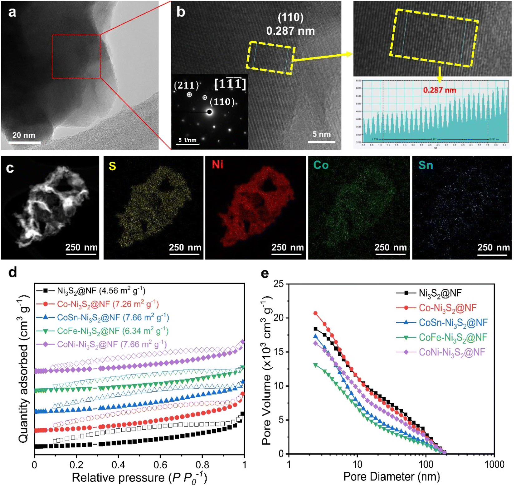 | ||
| Fig. 3 Physicochemical analysis of catalysts. (a) HRTEM image and (b) enlarged image with SAED pattern of CoSn-Ni3S2@NF. The right inset shows an atomic resolution image of yellow dashed box. (c) EDX spectra of each element of CoSn-Ni3S2@NF. (d) Nitrogen adsorption–desorption isotherms and (e) total pore volume and pore size of Ni3S2@NF, Co-Ni3S2@NF, and CoSn-Ni3S2@NF. | ||
Oxygen evolution reaction activity and stability
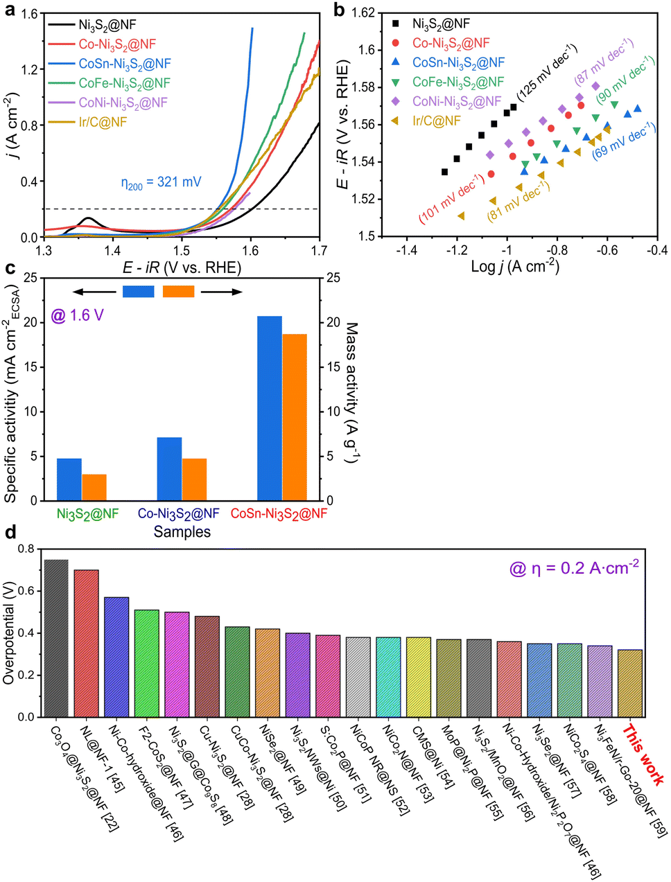
To investigate the electrochemical performances of Ni3S2@NF, Co–Ni3S2@NF, CoNi-Ni3S2@NF, CoFe-Ni3S2@NF, and CoSn-Ni3S2@NF, fundamental electrochemical analysis methods such as cyclic voltammetry (CV), linear sweep voltammetry (LSV), electrochemical impedance spectroscopy (EIS) were used. Linear sweep voltammetry (LSV) analysis was conducted in a 1 M KOH solution at a scan rate of 5 mV s−1 on a three-electrode system. IR compensation (85% IR drop compensation) was carried out to consider the influence of the electrolyte solution resistance during the electrochemical test. Fig. S4a† shows the OER polarization curves of Co-Ni3S2@NF that was synthesized under various hydrothermal conditions (120–160 °C for 1–7 h). Co-Ni3S2@NF prepared hydrothermally at 160 °C for 4 h exhibited the best OER activity, with a lower overpotential (η) of 341 mV at 0.2 A cm−2 than the other Co-Ni3S2@NF processed at different conditions (120 and 140 °C for 1 and 7 h). Moreover, Co-Ni3S2@NF annealed at 160 °C for 4 h possessed the smallest Tafel slope among all samples with a value of 97 mV dec−1 (Fig. S4b†), indicating that the hierarchically porous and Co-Ni3S2@NF nanosheet morphology significantly affected the OER performances (Fig. S2b†).The OER activities of pristine and doped-Ni3S2@NF electrocatalysts were evaluated in an O2-saturated 1 M KOH solution at a scan rate of 5 mV s−1 (Fig. 4a). CoSn-Ni3S2@NF exhibited the lowest overpotential of 321 mV at 0.2 A cm−2 for the OER among all tested samples. In particular, the best OER activity with the lowest η was obtained when the ratio of the amounts of Co and Sn precursors was 5![[thin space (1/6-em)]](https://www.rsc.org/images/entities/char_2009.gif) :1 among all samples prepared at differing proportions (Fig. S5a†). The Ir/C catalyst was also tested as the gold standard catalyst for OER under the same conditions. As shown in Fig. 4a, CoSn-Ni3S2 is even superior to Ir/C (324 mV). More specifically, the η at 0.2 A cm−2 increased in the following order: CoSn-Ni3S2@NF (1.551 V), CoFe-Ni3S2@NF (1.560 V), Co-Ni3S2@NF (1.571 V), CoNi-Ni3S2@NF (1.577 V), and Ni3S2@NF (1.602 V). Namely, doping Co element affects the OER performance of the Ni3S2 catalyst. It is particularly worth noting that the OER performance of the catalyst substantially improved when Co and Sn were co-doped in Ni3S2, and that the η of 298 and 321 mV were required to deliver the current densities of 0.1 and 0.2 A cm−2, respectively. To inspect the OER kinetic properties of catalysts, Tafel plots derived from polarization curves (ohmic resistance correct potential, E–iR vs. logj) are shown in Fig. 4b. The Tafel slopes of CoSn-Ni3S2@NF, CoFe-Ni3S2@NF, CoNi-Ni3S2@NF, Co-Ni3S2@NF, and Ni3S2@NF on Ni foam for the OER were 69, 90, 87, 101, and 125 mV dec−1, respectively, indicating that the incorporation of Sn (and Fe) atoms into Co-Ni3S2 triggers an enhancement in OER performance (Table 1). The Tafel slope of Ir/C from the OER polarization curves was 81 mV dec−1, indicating the excellent OER kinetics of CoSn-Ni3S2@NF.
:1 among all samples prepared at differing proportions (Fig. S5a†). The Ir/C catalyst was also tested as the gold standard catalyst for OER under the same conditions. As shown in Fig. 4a, CoSn-Ni3S2 is even superior to Ir/C (324 mV). More specifically, the η at 0.2 A cm−2 increased in the following order: CoSn-Ni3S2@NF (1.551 V), CoFe-Ni3S2@NF (1.560 V), Co-Ni3S2@NF (1.571 V), CoNi-Ni3S2@NF (1.577 V), and Ni3S2@NF (1.602 V). Namely, doping Co element affects the OER performance of the Ni3S2 catalyst. It is particularly worth noting that the OER performance of the catalyst substantially improved when Co and Sn were co-doped in Ni3S2, and that the η of 298 and 321 mV were required to deliver the current densities of 0.1 and 0.2 A cm−2, respectively. To inspect the OER kinetic properties of catalysts, Tafel plots derived from polarization curves (ohmic resistance correct potential, E–iR vs. logj) are shown in Fig. 4b. The Tafel slopes of CoSn-Ni3S2@NF, CoFe-Ni3S2@NF, CoNi-Ni3S2@NF, Co-Ni3S2@NF, and Ni3S2@NF on Ni foam for the OER were 69, 90, 87, 101, and 125 mV dec−1, respectively, indicating that the incorporation of Sn (and Fe) atoms into Co-Ni3S2 triggers an enhancement in OER performance (Table 1). The Tafel slope of Ir/C from the OER polarization curves was 81 mV dec−1, indicating the excellent OER kinetics of CoSn-Ni3S2@NF.
 | ||
| Fig. 4 Electrochemical properties of catalysts for OER. (a) OER polarization curves and (b) Tafel plots of Ni3S2@NF and T-Ni3S2@NF with Ir/C@NF. (c) Specific activities and mass activities of Ni3S2@NF, Co-Ni3S2@NF, and CoSn-Ni3S2@NF. (d) Comparison of η at 0.2 A cm−2 for CoSn-Ni3S2@NF with previously reported results for other nickel-based catalysts. | ||
| Catalyst | η @ 0.2 A cm−2 (V) | Tafel slope (mV dec−1) | Mass activity @ 1.6 V (A g−1) | Specific activity @ 1.6 V (mA cmECSA−2) | R ct (Ω cm2) | ECSA (cm2) |
|---|---|---|---|---|---|---|
| Ni3S2@NF | 372 | 125 | 3.0 | 4.8 | 0.24 | 37.0 |
| Co-Ni3S2@NF | 341 | 101 | 4.8 | 7.1 | 0.18 | 51.5 |
| CoNi-Ni3S2@NF | 347 | 87 | 4.0 | 5.5 | 0.18 | 57.8 |
| CoFe-Ni3S2@NF | 330 | 90 | 6.2 | 7.8 | 0.17 | 64.3 |
| CoSn-Ni3S2@NF | 321 | 69 | 18.7 | 20.7 | 0.11 | 72.3 |
To assess the scaling-up possibility of water electrolysis, the specific and mass OER activities of the Ni3S2@NF, Co-Ni3S2@NF, and CoSn-Ni3S2@NF catalysts were measured and are shown in Fig. 4c. The specific (mA cmBET−2) and mass activity (A g−1) were normalized by the BET surface area and the mass loading, respectively. The CoSn-Ni3S2@NF achieved an OER specific activity of 20.7 mA cmECSA−2 (and mass activity of 18.7 A g−1) at η = 370 mV (1.6 V vs. RHE), which is ∼6.3 times and ∼3.9 times that of the Ni3S2@NF (4.8 mA cmECSA−2 and 3.0 A g−1) and Co-Ni3S2@NF (7.1 mA cmECSA−2 and 4.8 A g−1), respectively, thus signifying its high feasibility for scalability of electrocatalysts with excellent intrinsic OER activity (Fig. S5b†). More importantly, after an extensive investigation of the activities of other catalysts, the CoSn-Ni3S2@NF was found to have a smaller η at 0.2 A cm−2 than previously reported NF-based OER electrocatalysts in alkaline media (Fig. 4d).22,28,45–59 The HER catalysis of the Ni3S2@NF, Co-Ni3S2@NF, and CoSn-Ni3S2@NF catalysts was also evaluated together with commercial Pt/C in O2-saturated 1.0 M KOH electrolyte using a typical three-electrode system. As shown in the polarization curve and Tafel plots of Fig. S4c and d,† Co-Ni3S2@NF annealed at 160 °C for 4 h exhibits the smallest η (360 mV at 0.4 A cm−2vs. RHE) and Tafel slope (119 mV dec−1) among all samples, thus confirming that the porous and nanostructured Co-Ni3S2@NF microstructure played an important role in the HER performances. Moreover, doping Sn element into the Co-Ni3S2@NF catalyst contributed to significantly improving the HER performance; the η of CoSn-Ni3S2@NF at 0.4 A cm−2 is nearly 70 and 40 mV lower than that of Ni3S2@NF and Co– Ni3S2@NF (Fig. S6a†). In addition, CoSn-Ni3S2@NF provides a lower Tafel slope of 69 mV dec−1 than those of Ni3S2@NF (151 mV dec−1) and Co-Ni3S2@NF (119 mV dec−1), thus indicating enhanced HER kinetics (Fig. S6b†). Further, the CoSn-Ni3S2@NF had a lower η at 0.4 A cm−2 than previously reported NF-based HER electrocatalysts in alkaline media (Fig. S6c†).50,60–65
In electrolysis cell, the operation stability of OER catalysts is an important factor. The long-term stability of catalysts was investigated by the applied constant current in a 1 M O2-saturated KOH solution. As shown in Fig. 5a, both Co-Ni3S2@NF and CoSn-Ni3S2@NF showed stable potential behavior (1.59 and 1.68 V) with small potential changes under chronopotentiometry at 0.2 A cm−2 and room temperature for 97 h. In addition, Co-Ni3S2@NF and CoSn-Ni3S2@NF present negligible performance degradations (0.3 and 4.5 mV decrease at 0.2 A cm−2) during the cycling test between 1.25 and 1.65 V for 1000 cycles (scan rate of 200 mV s−1), thus indicating the remarkable stability of nickel sulfides for OER (Fig. 5b). Moreover, the XRD patterns of Co-Ni3S2@NF and CoSn-Ni3S2@NF show insignificant change after the stability test (cycling test for 1000 cycles and chronopotentiometry test for 10 h) compared to those of pristine samples (Fig. 5c). The FE-SEM observation results also demonstrate that the morphology of the hierarchically porous CoSn-Ni3S2@NF nanosheets is well maintained after the OER cycle test, whereas the ends of the nanosheets become rounded in Co-Ni3S2@NF with a certain degree of agglomeration (Fig. 5d and e). However, the ICP-OES results showed that the atomic ratio (Co:Sn:Ni:S = 1.7:0.9:91.8:5.6) of CoSn-Ni3S2@NF electrocatalysts after stability test is somewhat different from that of proportion in the as-prepared sample (Co:Sn:Ni:S = 2.4:1.5:83.9:12.2), indicating some loss of CoSn-Ni3S2 catalysts on the NF during operations. Additional research is need to further improve the stability of Ni3S2@NF-based catalysts.
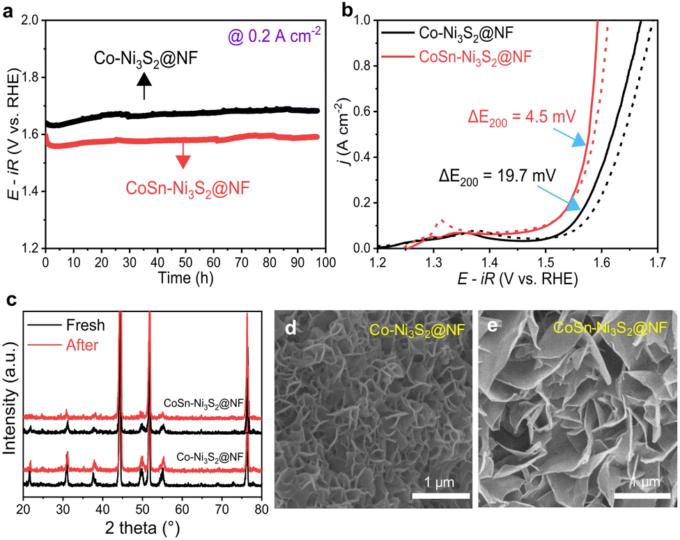 | ||
| Fig. 5 Long-term stability of OER catalysts. (a) Durability tests of Co-Ni3S2@NF and CoSn-Ni3S2@NF catalysts under 0.2 A cm−2 for 97 h. (b) Changes of OER activity curves of catalysts after 1000th cycling test between 1.25 V and 1.65 V. (c) XRD patterns of catalysts before and after durability test. FE-SEM image of (d) Co-Ni3S2@NF and (e) CoSn-Ni3S2@NF catalysts after durability test. | ||
Water-splitting cell performances of electrocatalysts
For industrial applications, AWE cells, which use low-cost power from renewable energy sources, need to satisfy requirements such as the supply of high current density (≥0.2 A cm−2) at low overpotentials and prolonged durability during oxidizing conditions.66 Single cell tests were performed using a nickel–iron layered double hydroxide (NiFe-LDH) on nickel foam for the hydrogen evolution reaction (HER, cathode) and OER anodic catalysts with a Zirfon PERL separator (with a thickness of 500 μm) (Fig. S7a†).67,68 Cell performance tests were conducted at a temperature of 80 °C (55 °C) and a flow rate of 30 wt% (1 M) KOH solution equal to 200 ccm (300 ccm).The I–V polarization characteristics of the electrolysis cells with Ni3S2@NF and CoSn-Ni3S2@NF OER catalysts are shown in Fig. 6. As can be seen in Fig. 6a (55 °C and 1 M KOH), a much higher current density of 0.643 A cm−2 was reached at a cell voltage of 2.0 V for CoSn-Ni3S2@NF cell, compared to those of the NF (0.227 A cm−2) and Ni3S2@NF (0.551 A cm−2) cells, thus indicating the excellent electrocatalytic activity CoSn-Ni3S2@NF for the OER and showing performance comparable to that of the electrolysis cells composed of any metal oxide catalyst that has been reported to date.69,70 In addition, the CoSn-Ni3S2@NF cell showed smaller electrode resistances than the Ni3S2@NF cell, as specified by the slopes of their I–V polarization curves. With increasing current density, the difference in the cell voltage between CoSn-Ni3S2@NF and Ni3S2@NF (and NF) is more substantial. This result may be attributed to not only the high intrinsic OER activity, but also the effective mass charge transfer. Further, the cell with CoSn-Ni3S2@NF demonstrated significantly high current densities of 0.7 and 1.367 A cm−2 at cell voltages of 1.8 and 2.0 V under the conditions of 80 °C and 30 wt% KOH (Fig. 6b). Table S2† summarized the electrochemical performance of recent OER catalysts in the electrolysis cells.
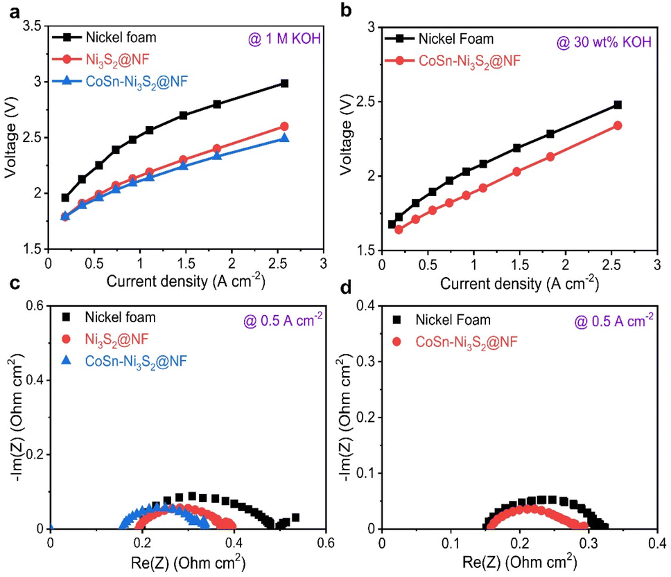 | ||
| Fig. 6 Electrochemical results of alkaline water electrolysis cells (with NF, Ni3S2@NF, and CoSn-Ni3S2@NF electrodes). Current–voltage curves of alkaline cells under (a) 1 M KOH at 55 °C and (b) 30 wt% KOH solution at 80 °C. EIS curves of alkaline cells at 0.5 A cm−2 under (c) 1 M KOH at 55 °C and (d) 30 wt% KOH solution at 80 °C. | ||
To differentiate the resistance components of the cells in detail, such as ohmic resistance of solution electrolyte (Rohmic), change transfer resistance (Rct), and mass-transfer resistance (Rmt), electrochemical impedance spectroscopy (EIS) was performed under galvanostatic control at 0.125, 0.5, and 1 A cm−2. Fig. 6c and d (Fig. S7b–e†) show complex-plane Nyquist plots of NF, Ni3S2@NF, and CoSn-Ni3S2@NF at 55 °C (1 M KOH) and 80 °C (30 wt% KOH) for the OER. In the EIS spectra, the high-frequency region indicates the Rohmic, which is composed of ionic resistance from the electrolyte and electrical connection. The intermediate- and low-frequency regions represent Rct (electron and ion transfer) and Rmt (ion adsorption, dissociation, and diffusion), respectively.71 CoSn-Ni3S2@NF exhibits the lowest Rct of 0.21, 0.07, and 0.06 Ω cm2 among all the test samples at 0.125, 0.5, and 1 A cm−2 (55 °C and 1 M KOH condition) for the OER, respectively. This confirms that doping of Sn and Co for Ni3S2@NF catalysts contributed significantly to the formation of an effective conducting path for charged ionic/electronic species in the OER.
Mechanistic study
To identify the decisive factor driving the excellent OER performances of CoSn-Ni3S2@NF, the surface chemical states and elemental compositions of the catalysts were analyzed by X-ray photoelectron spectroscopy (XPS). Fig. 7a shows the Ni 2p core level XPS spectra of the Ni3S2@NF, Co-Ni3S2@NF, and CoSn-Ni3S2@NF catalysts. Using mixed Gaussian–Lorentzian fitting, the peaks at ∼856.4 and ∼855.2 eV can be assigned to Ni3+ and Ni2+ (2p3/2), respectively, while the peaks at ∼874.2 and ∼872.8 eV can be assigned to Ni3+ and Ni2+ (2p1/2), respectively. The peaks at 879.4 eV and 861.4 eV can be considered to be satellite peaks of Ni 2p.72 The relative amount of the oxidation states for Ni ions was assessed from the integrated area ratios of the sub-peaks. Interestingly, the ratio of Ni2+/Ni3+ increased from 0.80 to 0.84 when doped with Co (Co-Ni3S2@NF) in the heazlewoodite Ni3S2 structure, and it further increased significantly to 1.34 in the case that was co-doped with Sn (CoSn-Ni3S2@NF). This is because the multivalent Ni ions in Ni3S2 phase can be balanced by modifying higher valence Ni3+ to lower valence Ni2+ by increasing the number of electrons (holes) in the Ni3S2 phase to satisfy the electrical neutrality condition.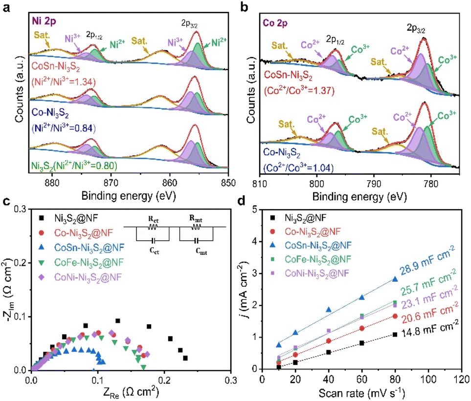 | ||
| Fig. 7 XPS spectra for (a) Ni 2p and (b) Co 2p of the Ni3S2@NF, Co-Ni3S2@NF, and CoSn-Ni3S2@NF catalysts. (c) EIS analysis of Ni3S2@NF, Co-Ni3S2@NF, and CoSn-Ni3S2@NF catalysts with equivalent circuit model. (d) Linear plots of double layer charging currents with different scan rates (10–80 mV s−1) derived from CV diagrams between 0.1–0.2 V (vs. RHE). | ||
The same result can be applied in the case of Co ion. The Co 2p XPS spectra of the Co-Ni3S2@NF and CoSn-Ni3S2@NF exhibit doublet peaks comprised of two spin orbital lines, Co 2p3/2 and Co 2p1/2 at ∼780.3 and ∼796.7 eV, respectively, thus indicating the coexistence of Co2+ (∼781.6, ∼797.4 eV) and Co3+ (∼780.6, ∼796.2 eV) oxidation states on the catalyst (Fig. 7b).73 It should be noted that the ratio of Co2+/Co3+ (in Co-Ni3S2) also increased from 1.04 to 1.30 when co-doped with Sn (CoSn-Ni3S2@NF), which endorses that the incorporation of Co and Sn ions in the Ni3S2 converted the electronic configuration of Ni ions with the formation of a highly defective structure. Interactions of multivalent Ni and Co ions with different electronic structures in the heazlewoodite phase could afford plenty of active sites that are beneficial for the OER.74 Fig. S8a† showed Sn 3d peaks of CoSn-Ni3S2@NF. In the XPS spectra for Sn 3d, two peaks of Sn 3d3/2 and Sn 3d5/2 designate the coexistence of Sn2+ (∼486.0, ∼494.5 eV) and Sn4+ (∼486.6, ∼495.1 eV) oxidation states, thus indicating that Sn ions were successfully doped into CoSn-Ni3S2@NF.24 This phenomenon indicates that Sn doping changed the oxidation state of Co, resulting in some significantly faster charge transfers in CoSn-Ni3S2@NF. For the S 2p XPS spectra of the pristine and doped Ni3S2@NF catalysts (Fig. S8b†), the obtained peaks located at ∼161.6(8) eV and ∼162.9(4) eV respectively corresponded to S 2p3/2 and S 2p1/2, thus revealing the existence of S2− species by bonding of metal–sulfur.75 In particular, the strong peak at a higher value of ∼162.4 eV after doping Sn into the Ni3S2 surface is assigned to the sulfur with low coordination, implying the generation of a high density of S vacancies, whereas the peak at ∼161.8 eV can be considered to be Ni–S bonds.72,76
Electrochemical impedance spectroscopy (EIS) was used in a three-electrode cell configuration to examine the fundamental origin of the high OER activity of CoSn-Ni3S2@NF. As shown in Fig. 7c, based on the equivalent circuit model (at 1.6 vs. RHE for OER), the electrode polarization resistance (Rct + Rmt) values were considerably reduced in the order of Ni3S2@NF (0.24 Ω cm2) > Co-Ni3S2@NF (0.18 Ω cm2) > CoSn-Ni3S2@NF (0.11 Ω cm2), thus signifying the beneficial effects of the co-doping of Sn and Co on the charge transfer during the OERs. Fig. 7d shows the measured charging current density (jc) plots as a function of scan rates (v = 10–80 mV s−1) in the non-faradaic range (0.05–0.25 vs. RHE) that come from the CV test (Fig. S9†). The double layer capacitance (Cdl) was obtained by calculating the slopes of the jc plots as a function of v (Fig. S9†).77 The Cdl values of Ni3S2@NF, Co-Ni3S2@NF, and CoSn-Ni3S2@NF were 4.7, 20.6, and 28.9 mF cm−2, respectively, in 1 M KOH. Further, as a critical indicator of catalysts for OER catalytic activity, the electrochemically active surface area (ECSA) of the catalyst was determined by Cdl × S/Cs, where Cs and S are the specific capacitance and surface area of the working electrode, respectively. The ECSA of CoSn-Ni3S2@NF (72.3 cm2) was much higher than those of Co-Ni3S2@NF (51.5 cm2) and Ni3S2@NF (37.0 cm2), therefore demonstrating that co-doping of Co and Sn in the Ni3S2 has triggered intrinsic OER catalytic activity with more effective active sites for charged ionic/electronic species.
By combining the experiment and DFT calculations, we attempted to determine the cause of the measured high OER activities of metal doped Ni3S2. Our results suggest that this can be understood in terms of (i) defect formation and (ii) Ni 3d-band center. Overall, we find that two dopants, Co and Sn, contribute differently to the OER activity (Table 2); the Co dopant not only becomes an activation site by itself, but it also makes the Ni 3d-band center higher, and the Sn dopant accelerates VS formation (that shifts upward Ni 3d-band center) while hardly changing the Ni 3d-band center. Therefore, CoSn co-doping maximizes the OER activities as measured in the experiment.
| Contribution | Co-Ni3S2 | Sn-Ni3S2 | CoSn-Ni3S2 |
|---|---|---|---|
| Increasing of activation site | +, Co dopant | +, VS | ++, Co dopant & VS |
| Shift of Ni 3d-band center to EF | +, by Co dopant | +, by VS (barely changed by Sn) | ++, by Co & VS |
| Increasing of electron carriers | +, by VS | +, by VS | |
| Total | ++ | +++ | +++++ |
| Formation energy (eV) | Ni3S2 | Co-Ni3S2 | Sn-Ni3S2 | CoSn-Ni3S2 |
|---|---|---|---|---|
| V Ni | 0.785 | 0.808 | −0.105 | −0.114 |
| V S | 1.681 | 1.952 | −1.245 | −1.339 |
| Ni 3d-band center (eV) | Ni3S2 | Co-Ni3S2 | Sn-Ni3S2 | CoSn-Ni3S2 |
|---|---|---|---|---|
| Without vacancies | −3.07 | −3.03 (−2.39) | −3.07 | −3.06 (−2.76) |
| V Ni | −3.04 | −3.03 (−2.30) | −3.07 | −3.06 (−2.76) |
| V S | −3.00 | −3.00 (−2.05) | −3.02 | −3.02 (−2.59) |
Interestingly, Sn and Co co-doping leads to a crossover of the dominant vacancy type. In Ni3S2 and Co-Ni3S2, VNi is more likely to form than VS, since Ef(VNi) is calculated to be lower than Ef(VS). On the other hand, after co-doping of Sn and Co, the VS formation is much more pronounced than the VNi formation. For example, Ef(VNi) is nearly ten times greater than Ef(VS) in CoSn-Ni3S2 (note that, since the calculation of the defect formation energy is based on a thermodynamic equilibrium growth environment whereas our experiment is not, the absolute formation energy is less meaningful in our case). Therefore, although there may exist a VNi with moderate content, the number of electron carriers increases due to a larger content of VS (electron supplier) than that of VNi (hole supplier). This is consistent with the experimentally observed ratio of Ni2+/Ni3+ (increased from 0.80 in Ni3S2 to 1.34 in CoSn-Ni3S2) and the ratio of Co2+/Co3+ (increased from 1.04 in Co-Ni3S2 to 1.37 in CoSn-Ni3S2), which possibly result from an increase in electrons relative to holes. More importantly, the observation of higher (greater) OER activity (VS content than VNi content) of Sn-Ni3S2@NF and CoSn-Ni3S2@NF compared to Co-Ni3S2@NF indicates that VS is more important than VNi in terms of the OER activity.
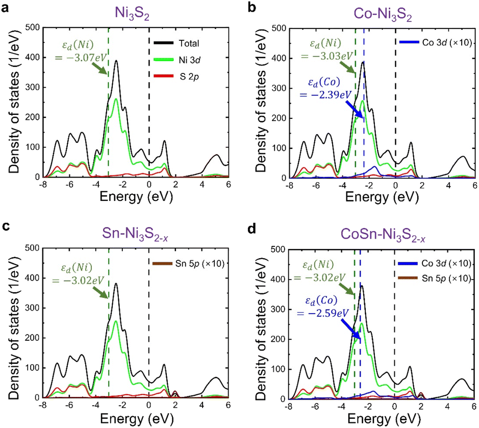 | ||
| Fig. 8 Calculated DOS for (a) Ni3S2, (b) Co-Ni3S2, (c) Sn-Ni3S2−x, and (d) CoSn-Ni3S2−x. Sn and CoSn-doping leads to VS formation in Ni3S2, and hence (c) and (d) are responsible for the supercells including one VS. Olive and blue dashed lines denote Ni 3d-band center (εd(Ni)) and Co 3d-band center (εd(Co)), respectively, and black line indicates Fermi level. DOS values of Co and Sn components are multiplied by ten for easy visualization. | ||
Conclusions
With the goal of designing a high-performance, durable, and cost-effective electrocatalyst, we demonstrated that multi-valent transition metal (Co) and post-transition metal (Sn)-co-doped Ni3S2@NF are highly active and durable for the OERs in alkaline medium. The hierarchically porous and nanostructured CoSn-Ni3S2@NF catalysts were synthesized via a facile and reproducible hydrothermal synthesis method. CoSn-Ni3S2@NF exhibited better OER activity with a lower η of 321 mV at 0.2 A cm−2 (Tafel slope of 69 mV dec−1) than the CoFe-Ni3S2@NF (330 mV, 90 mV dec−1), Co-Ni3S2@NF (341 mV, 101 mV dec−1), and Ni3S2@NF (372 mV, 125 mV dec−1) catalysts. More importantly, the η of CoSn-Ni3S2@NF at 0.2 A cm−2 was smaller than NF-based OER electrocatalysts that have previously been reported, including Ir/C (324 mV, 81 mV dec−1) in alkaline media, which validates that the incorporation of Sn and Co atoms into Ni3S2 triggers OER performance enhancement. In addition, CoSn-Ni3S2@NF presented negligible performance degradations during the constant current (at 0.2 A cm−2 for 10 h) and voltage cycling test between 1.25 and 1.65 V for 1000 cycles, thus indicating remarkable stability for the OER. Further, the CoSn-Ni3S2@NF alkaline water electrolysis cell demonstrated excellent polarization characteristics corresponding to a cell voltage of 2.0 V at a current density of 1.367 A cm−2, 80 °C, and 30 wt% KOH condition. Experimental results and DFT calculations revealed that two dopants, Co and Sn, contribute differently to the OER activity of CoSn-Ni3S2@NF; the Co dopant becomes an activation site and makes the Ni 3d-band center higher, while the Sn dopant contributes to the OER activity by generating donor-type VS that is an activation site, and it also shifts the Ni 3d-band center upward and closer to the Fermi level. Therefore, CoSn co-doping maximizes the OER activities as measured experimentally. This finding provides new possibilities for designing high performance transition and post-transition metal sulfides electrocatalysts for overall water electrolysis technologies.Author contributions
Won Young An: conceptualization, methodology, investigation, validation, data acquiring & analysis, visualization, writing – original draft. Hyungwoo Lee: data curation, software, data acquiring & analysis, writing – original draft. Sung Ryul Choi: methodology, investigation, validation, data acquiring & analysis. Sungyong Choi: methodology, investigation, validation, data acquiring & analysis. Hyun-Seok Cho: methodology, resources, supervision, writing – review & editing. Minseok Choi: data curation, software, supervision, writing – review & editing. Jun-Young Park: conceptualization, methodology, funding acquisition, supervision, writing – review & editing.Conflicts of interest
There are no conflicts to declare.Acknowledgements
This research was supported by the Basic Science Research Program through the National Research Foundation of Korea (NRF) funded by the Ministry of Education (NRF-2020R1A6A1A03043435, NRF-2021R1F1A1051716) and Technology Innovation Program (20011633) funded by the Ministry of Trade, Industry & Energy of (MOTIE) Korea.References
- H. Zhao and Y. Lei, Adv. Energy Mater., 2020, 10, 2001460 CrossRef CAS.
- S. R. Choi, M. Lim, D. Y. Kim, W. Y. An, S. W. Lee, S. Choi, S. J. Bae, S.-D. Yim and J.-Y. Park, Int. J. Hydrogen Energy, 2022, 47, 17379–17392 CrossRef CAS.
- F. Qureshi, M. Yusuf, H. Kamyab, S. Zaidi, M. J. Khalil, M. A. Khan, M. A. Alam, F. Masood, L. Bazli and S. Chelliapan, Sustain. Energy Technol. Assessments, 2022, 53, 102677 CrossRef.
- S. Singla, N. P. Shetti, S. Basu, K. Mondal and T. M. Aminabhavi, J. Environ. Manage., 2022, 302, 113963 CrossRef CAS PubMed.
- S. Sadeghi, S. Ghandehariun and M. A. Rosen, Energy, 2020, 208, 118347 CrossRef CAS.
- A. Al-Qahtani, B. Parkinson, K. Hellgardt, N. Shah and G. Guillen-Gosalbez, Appl. Energy, 2021, 281, 115958 CrossRef CAS.
- Z. Y. Yu, Y. Duan, X. Y. Feng, X. Yu, M. R. Gao and S. H. Yu, Adv. Mater., 2021, 33, 2007100 CrossRef CAS PubMed.
- E. Fabbri, A. Habereder, K. Waltar, R. Kötz and T. J. Schmidt, Catal. Sci. Technol., 2014, 4, 3800–3821 RSC.
- Z. Li, X. Wu, X. Jiang, B. Shen, Z. Teng, D. Sun, G. Fu and Y. Tang, Advanced Powder Materials, 2022, 1, 100020 CrossRef.
- S. Anwar, F. Khan, Y. Zhang and A. Djire, Int. J. Hydrogen Energy, 2021, 46, 32284–32317 CrossRef CAS.
- P. Chen and X. Hu, Adv. Energy Mater., 2020, 10, 2002285 CrossRef CAS.
- H. M. Amin and U. P. Apfel, Eur. J. Inorg. Chem., 2020, 2020, 2679–2690 CrossRef CAS.
- X. Wang, X. Huang, W. Gao, Y. Tang, P. Jiang, K. Lan, R. Yang, B. Wang and R. Li, J. Mater. Chem. A, 2018, 6, 3684–3691 RSC.
- D. Y. Kim, H. Lee, S. R. Choi, S. Choi, W. Y. An, H.-S. Cho, M. Choi and J.-Y. Park, J. Alloys Compd., 2022, 914, 165305 CrossRef CAS.
- C. Manjunatha, N. Srinivasa, S. Chaitra, M. Sudeep, R. C. Kumar and S. Ashoka, Mater. Today Energy, 2020, 16, 100414 CrossRef.
- L. Zeng, K. Sun, X. Wang, Y. Liu, Y. Pan, Z. Liu, D. Cao, Y. Song, S. Liu and C. Liu, Nano Energy, 2018, 51, 26–36 CrossRef CAS.
- W. Zhou, X.-J. Wu, X. Cao, X. Huang, C. Tan, J. Tian, H. Liu, J. Wang and H. Zhang, Energy Environ. Sci., 2013, 6, 2921–2924 RSC.
- Q. Lin, Y. Zhu, Z. Hu, Y. Yin, H.-J. Lin, C.-T. Chen, X. Zhang, Z. Shao and H. Wang, J. Mater. Chem. A, 2020, 8, 6480–6486 RSC.
- P. Zhang, Z. Wang, X. Hou, J. Lu, X. Xu, C. Stampfl and C. Hu, Appl. Catal., A, 2021, 624, 118324 CrossRef CAS.
- J.-J. Duan, Z. Han, R.-L. Zhang, J.-J. Feng, L. Zhang, Q.-L. Zhang and A.-J. Wang, J. Colloid Interface Sci., 2021, 588, 248–256 CrossRef CAS PubMed.
- S. R. Choi, J.-I. Lee, H. Park, S. W. Lee, D. Y. Kim, W. Y. An, J. H. Kim, J. Kim, H.-S. Cho and J.-Y. Park, Chem. Eng. J., 2021, 409, 128226 CrossRef CAS.
- Y. Gong, Z. Xu, H. Pan, Y. Lin, Z. Yang and X. Du, J. Mater. Chem. A, 2018, 6, 5098–5106 RSC.
- S. Song, Y. Wang, W. Li, P. Tian, S. Zhou, H. Gao, X. Tian and J. Zang, J. Alloys Compd., 2020, 827, 154299 CrossRef CAS.
- J. Yu, F.-X. Ma, Y. Du, P.-P. Wang, C.-Y. Xu and L. Zhen, ChemElectroChem, 2017, 4, 594–600 CrossRef CAS.
- J. Jian, L. Yuan, H. Qi, X. Sun, L. Zhang, H. Li, H. Yuan and S. Feng, ACS Appl. Mater. Interfaces, 2018, 10, 40568–40576 CrossRef CAS PubMed.
- G. Zhang, Y.-S. Feng, W.-T. Lu, D. He, C.-Y. Wang, Y.-K. Li, X.-Y. Wang and F.-F. Cao, ACS Catal., 2018, 8, 5431–5441 CrossRef CAS.
- B. Fei, Z. Chen, J. Liu, H. Xu, X. Yan, H. Qing, M. Chen and R. Wu, Adv. Energy Mater., 2020, 10, 2001963 CrossRef CAS.
- J.-F. Qin, M. Yang, S. Hou, B. Dong, T.-S. Chen, X. Ma, J.-Y. Xie, Y.-N. Zhou, J. Nan and Y.-M. Chai, Appl. Surf. Sci., 2020, 502, 144172 CrossRef CAS.
- X. Wu, T. Zhang, J. Wei, P. Feng, X. Yan and Y. Tang, Nano Res., 2020, 13, 2130–2135 CrossRef CAS.
- H. Sun, Z. Yan, F. Liu, W. Xu, F. Cheng and J. Chen, Adv. Mater., 2020, 32, 1806326 CrossRef CAS PubMed.
- N. Mahmood, Y. Yao, J. W. Zhang, L. Pan, X. Zhang and J. J. Zou, Adv. Sci., 2018, 5, 1700464 CrossRef PubMed.
- N. Chen, S. Y. Paek, J. Y. Lee, J. H. Park, S. Y. Lee and Y. M. Lee, Energy Environ. Sci., 2021, 14, 6338–6348 RSC.
- X. Luo, P. Ji, P. Wang, R. Cheng, D. Chen, C. Lin, J. Zhang, J. He, Z. Shi and N. Li, Adv. Energy Mater., 2020, 10, 1903891 CrossRef CAS.
- L. Ma, K. Zhang, S. Wang, L. Gao, Y. Sun, Q. Liu, J. Guo and X. Zhang, Appl. Surf. Sci., 2019, 489, 815–823 CrossRef CAS.
- J. P. Perdew, K. Burke and M. Ernzerhof, Phys. Rev. Lett., 1996, 77, 3865 CrossRef CAS PubMed.
- G. Kresse and J. Hafner, Phys. Rev. B: Condens. Matter Mater. Phys., 1993, 47, 558 CrossRef CAS PubMed.
- S. L. Dudarev, G. A. Botton, S. Y. Savrasov, C. Humphreys and A. P. Sutton, Phys. Rev. B: Condens. Matter Mater. Phys., 1998, 57, 1505 CrossRef CAS.
- C. Freysoldt, B. Grabowski, T. Hickel, J. Neugebauer, G. Kresse, A. Janotti and C. G. Van de Walle, Rev. Mod. Phys., 2014, 86, 253 CrossRef.
- X. Liu, Y. Li, N. Chen, D. Deng, X. Xing and Y. Wang, Electrochim. Acta, 2016, 213, 730–739 CrossRef CAS.
- T. Ai, H. Wang, W. Bao, L. Feng, X. Zou, X. Wei, L. Ding, Z. Deng and B. Rao, Chem. Eng. J., 2022, 450, 138358 CrossRef CAS.
- A. Ashok, A. Kumar, J. Ponraj and S. A. Mansour, Carbon, 2020, 170, 452–463 CrossRef CAS.
- G. Gibbs, R. Downs, C. Prewitt, K. M. Rosso, N. Ross and D. F. Cox, J. Phys. Chem. B, 2005, 109, 21788–21795 CrossRef CAS PubMed.
- Q. Xu, M. Chu, M. Liu, J. Zhang, H. Jiang and C. Li, Chem. Eng. J., 2021, 411, 128488 CrossRef CAS.
- B. Wu, H. Qian, Z. Nie, Z. Luo, Z. Wu, P. Liu, H. He, J. Wu, S. Chen and F. Zhang, J. Energy Chem., 2020, 46, 178–186 CrossRef.
- T. Zhu, L. Zhu, J. Wang and G. W. Ho, J. Mater. Chem. A, 2016, 4, 13916–13922 RSC.
- N. R. Chodankar, I. V. Bagal, S. W. Ryu, Y. K. Han and D. H. Kim, ChemCatChem, 2019, 11, 4256–4261 CrossRef CAS.
- L. Lei, D. Huang, C. Zhang, R. Deng, S. Chen and Z. Li, J. Catal., 2020, 385, 129–139 CrossRef CAS.
- Q. Dong, Y. Zhang, Z. Dai, P. Wang, M. Zhao, J. Shao, W. Huang and X. Dong, Nano Res., 2018, 11, 1389–1398 CrossRef CAS.
- X. Li, G.-Q. Han, Y.-R. Liu, B. Dong, X. Shang, W.-H. Hu, Y.-M. Chai, Y.-Q. Liu and C.-G. Liu, Electrochim. Acta, 2016, 205, 77–84 CrossRef CAS.
- D. Zhang, J. Li, J. Luo, P. Xu, L. Wei, D. Zhou, W. Xu and D. Yuan, Nanotechnology, 2018, 29, 245402 CrossRef PubMed.
- M. A. R. Anjum, M. D. Bhatt, M. H. Lee and J. S. Lee, Chem. Mater., 2018, 30, 8861–8870 CrossRef CAS.
- J.-G. Wang, W. Hua, M. Li, H. Liu, M. Shao and B. Wei, ACS Appl. Mater. Interfaces, 2018, 10, 41237–41245 CrossRef CAS PubMed.
- Y. Wang, B. Zhang, W. Pan, H. Ma and J. Zhang, ChemSusChem, 2017, 10, 4170–4177 CrossRef CAS PubMed.
- J. Li, W. Xu, J. Luo, D. Zhou, D. Zhang, L. Wei, P. Xu and D. Yuan, Nano-Micro Lett., 2018, 10, 1–10 CrossRef PubMed.
- C. Du, M. Shang, J. Mao and W. Song, J. Mater. Chem. A, 2017, 5, 15940–15949 RSC.
- Y. Xiong, L. Xu, C. Jin and Q. Sun, Appl. Catal., B, 2019, 254, 329–338 CrossRef CAS.
- A. Sivanantham and S. Shanmugam, Appl. Catal., B, 2017, 203, 485–493 CrossRef CAS.
- J. Yu, C. Lv, L. Zhao, L. Zhang, Z. Wang and Q. Liu, Adv. Mater. Interfaces, 2018, 5, 1701396 CrossRef.
- Y. Gu, S. Chen, J. Ren, Y. A. Jia, C. Chen, S. Komarneni, D. Yang and X. Yao, ACS Nano, 2018, 12, 245–253 CrossRef CAS PubMed.
- K.-L. Yan, J.-F. Qin, Z.-Z. Liu, B. Dong, J.-Q. Chi, W.-K. Gao, J.-H. Lin, Y.-M. Chai and C.-G. Liu, Chem. Eng. J., 2018, 334, 922–931 CrossRef CAS.
- K. S. Bhat and H. Nagaraja, Int. J. Hydrogen Energy, 2018, 43, 19851–19863 CrossRef CAS.
- X. Wang, R. Liu, Y. Zhang, L. Zeng and A. Liu, Appl. Surf. Sci., 2018, 456, 164–173 CrossRef CAS.
- S. Shit, S. Chhetri, W. Jang, N. C. Murmu, H. Koo, P. Samanta and T. Kuila, ACS Appl. Mater. Interfaces, 2018, 10, 27712–27722 CrossRef CAS PubMed.
- L. Zhang, K. Xiong, S. Chen, L. Li, Z. Deng and Z. Wei, J. Power Sources, 2015, 274, 114–120 CrossRef CAS.
- J. Lin, H. Wang, X. Zheng, Y. Du, C. Zhao, J. Qi, J. Cao, W. Fei and J. Feng, J. Power Sources, 2018, 401, 329–335 CrossRef CAS.
- Y. Li, B. Wei, Z. Yu, O. Bondarchuk, A. Araujo, I. Amorim, N. Zhang, J. Xu, I. C. Neves and L. Liu, ACS Sustainable Chem. Eng., 2020, 8, 10193–10200 CrossRef CAS.
- Y. Zhu, X. Wang, X. Zhu, Z. Wu, D. Zhao, F. Wang, D. Sun, Y. Tang, H. Li and G. Fu, Small, 2022, 19, 2206531 CrossRef PubMed.
- S. Chen, Z. Zheng, Q. Li, H. Wan, G. Chen, N. Zhang, X. Liu and R. Ma, J. Mater. Chem. A, 2023, 11, 1944–1953 RSC.
- E. López-Fernández, J. Gil-Rostra, J. P. Espinos, A. R. González-Elipe, F. Yubero and A. de Lucas-Consuegra, J. Power Sources, 2019, 415, 136–144 CrossRef.
- G.-C. Chen, T. H. Wondimu, H.-C. Huang, K.-C. Wang and C.-H. Wang, Int. J. Hydrogen Energy, 2019, 44, 10174–10181 CrossRef CAS.
- J. E. Park, S. Y. Kang, S.-H. Oh, J. K. Kim, M. S. Lim, C.-Y. Ahn, Y.-H. Cho and Y.-E. Sung, Electrochim. Acta, 2019, 295, 99–106 CrossRef CAS.
- F. Lu, M. Zhou, W. Li, Q. Weng, C. Li, Y. Xue, X. Jiang, X. Zeng, Y. Bando and D. Golberg, Nano Energy, 2016, 26, 313–323 CrossRef CAS.
- J. Feng, Y. Meng, Z. Lian, L. Fang, Z. Long, Y. Li and Y. Song, RSC Adv., 2019, 9, 9729–9736 RSC.
- L. Tang, T. Fan, Z. Chen, J. Tian, H. Guo, M. Peng, F. Zuo, X. Fu, M. Li and Y. Bu, Chem. Eng. J., 2021, 417, 129324 CrossRef CAS.
- Z. Li, D. Zhao, C. Xu, J. Ning, Y. Zhong, Z. Zhang, Y. Wang and Y. Hu, Electrochim. Acta, 2018, 278, 33–41 CrossRef CAS.
- S.-C. Sun, F.-X. Ma, Y. Li, L.-W. Dong, H. Liu, C.-M. Jiang, B. Song, L. Zhen and C.-Y. Xu, Sustainable Energy Fuels, 2020, 4, 3326–3333 RSC.
- Y. Liu, X. Liang, L. Gu, Y. Zhang, G.-D. Li, X. Zou and J.-S. Chen, Nat. Commun., 2018, 9, 1–10 CrossRef PubMed.
- Y. Jia, K. Jiang, H. Wang and X. Yao, Chem, 2019, 5, 1371–1397 CAS.
- B. Hammer and J. K. Nørskov, Adv. Catal., 2000, 45, 71–129 CAS.
- H. Su, S. Song, S. Li, Y. Gao, L. Ge, W. Song, T. Ma and J. Liu, Appl. Catal., B, 2021, 293, 120225 CrossRef CAS.
Footnotes |
| † Electronic supplementary information (ESI) available. See DOI: https://doi.org/10.1039/d2ta09361h |
| ‡ These authors contributed equally to this work. |
| This journal is © The Royal Society of Chemistry 2023 |